WO1999062064A1 - Method for producing optical recording medium and optical recording medium - Google Patents
Method for producing optical recording medium and optical recording medium Download PDFInfo
- Publication number
- WO1999062064A1 WO1999062064A1 PCT/JP1999/002720 JP9902720W WO9962064A1 WO 1999062064 A1 WO1999062064 A1 WO 1999062064A1 JP 9902720 W JP9902720 W JP 9902720W WO 9962064 A1 WO9962064 A1 WO 9962064A1
- Authority
- WO
- WIPO (PCT)
- Prior art keywords
- dye
- optical recording
- recording medium
- coating
- solvent
- Prior art date
- Legal status (The legal status is an assumption and is not a legal conclusion. Google has not performed a legal analysis and makes no representation as to the accuracy of the status listed.)
- Ceased
Links
Classifications
-
- G—PHYSICS
- G11—INFORMATION STORAGE
- G11B—INFORMATION STORAGE BASED ON RELATIVE MOVEMENT BETWEEN RECORD CARRIER AND TRANSDUCER
- G11B7/00—Recording or reproducing by optical means, e.g. recording using a thermal beam of optical radiation by modifying optical properties or the physical structure, reproducing using an optical beam at lower power by sensing optical properties; Record carriers therefor
- G11B7/24—Record carriers characterised by shape, structure or physical properties, or by the selection of the material
- G11B7/241—Record carriers characterised by shape, structure or physical properties, or by the selection of the material characterised by the selection of the material
- G11B7/242—Record carriers characterised by shape, structure or physical properties, or by the selection of the material characterised by the selection of the material of recording layers
- G11B7/244—Record carriers characterised by shape, structure or physical properties, or by the selection of the material characterised by the selection of the material of recording layers comprising organic materials only
- G11B7/249—Record carriers characterised by shape, structure or physical properties, or by the selection of the material characterised by the selection of the material of recording layers comprising organic materials only containing organometallic compounds
- G11B7/2495—Record carriers characterised by shape, structure or physical properties, or by the selection of the material characterised by the selection of the material of recording layers comprising organic materials only containing organometallic compounds as anions
-
- G—PHYSICS
- G11—INFORMATION STORAGE
- G11B—INFORMATION STORAGE BASED ON RELATIVE MOVEMENT BETWEEN RECORD CARRIER AND TRANSDUCER
- G11B7/00—Recording or reproducing by optical means, e.g. recording using a thermal beam of optical radiation by modifying optical properties or the physical structure, reproducing using an optical beam at lower power by sensing optical properties; Record carriers therefor
- G11B7/24—Record carriers characterised by shape, structure or physical properties, or by the selection of the material
- G11B7/241—Record carriers characterised by shape, structure or physical properties, or by the selection of the material characterised by the selection of the material
- G11B7/242—Record carriers characterised by shape, structure or physical properties, or by the selection of the material characterised by the selection of the material of recording layers
- G11B7/244—Record carriers characterised by shape, structure or physical properties, or by the selection of the material characterised by the selection of the material of recording layers comprising organic materials only
- G11B7/246—Record carriers characterised by shape, structure or physical properties, or by the selection of the material characterised by the selection of the material of recording layers comprising organic materials only containing dyes
- G11B7/2467—Record carriers characterised by shape, structure or physical properties, or by the selection of the material characterised by the selection of the material of recording layers comprising organic materials only containing dyes azo-dyes
-
- G—PHYSICS
- G11—INFORMATION STORAGE
- G11B—INFORMATION STORAGE BASED ON RELATIVE MOVEMENT BETWEEN RECORD CARRIER AND TRANSDUCER
- G11B7/00—Recording or reproducing by optical means, e.g. recording using a thermal beam of optical radiation by modifying optical properties or the physical structure, reproducing using an optical beam at lower power by sensing optical properties; Record carriers therefor
- G11B7/24—Record carriers characterised by shape, structure or physical properties, or by the selection of the material
- G11B7/241—Record carriers characterised by shape, structure or physical properties, or by the selection of the material characterised by the selection of the material
- G11B7/242—Record carriers characterised by shape, structure or physical properties, or by the selection of the material characterised by the selection of the material of recording layers
- G11B7/244—Record carriers characterised by shape, structure or physical properties, or by the selection of the material characterised by the selection of the material of recording layers comprising organic materials only
- G11B7/246—Record carriers characterised by shape, structure or physical properties, or by the selection of the material characterised by the selection of the material of recording layers comprising organic materials only containing dyes
- G11B7/247—Record carriers characterised by shape, structure or physical properties, or by the selection of the material characterised by the selection of the material of recording layers comprising organic materials only containing dyes methine or polymethine dyes
- G11B7/2472—Record carriers characterised by shape, structure or physical properties, or by the selection of the material characterised by the selection of the material of recording layers comprising organic materials only containing dyes methine or polymethine dyes cyanine
-
- G—PHYSICS
- G11—INFORMATION STORAGE
- G11B—INFORMATION STORAGE BASED ON RELATIVE MOVEMENT BETWEEN RECORD CARRIER AND TRANSDUCER
- G11B7/00—Recording or reproducing by optical means, e.g. recording using a thermal beam of optical radiation by modifying optical properties or the physical structure, reproducing using an optical beam at lower power by sensing optical properties; Record carriers therefor
- G11B7/24—Record carriers characterised by shape, structure or physical properties, or by the selection of the material
- G11B7/26—Apparatus or processes specially adapted for the manufacture of record carriers
-
- G—PHYSICS
- G11—INFORMATION STORAGE
- G11B—INFORMATION STORAGE BASED ON RELATIVE MOVEMENT BETWEEN RECORD CARRIER AND TRANSDUCER
- G11B7/00—Recording or reproducing by optical means, e.g. recording using a thermal beam of optical radiation by modifying optical properties or the physical structure, reproducing using an optical beam at lower power by sensing optical properties; Record carriers therefor
- G11B7/24—Record carriers characterised by shape, structure or physical properties, or by the selection of the material
- G11B7/241—Record carriers characterised by shape, structure or physical properties, or by the selection of the material characterised by the selection of the material
- G11B7/242—Record carriers characterised by shape, structure or physical properties, or by the selection of the material characterised by the selection of the material of recording layers
- G11B7/244—Record carriers characterised by shape, structure or physical properties, or by the selection of the material characterised by the selection of the material of recording layers comprising organic materials only
- G11B7/246—Record carriers characterised by shape, structure or physical properties, or by the selection of the material characterised by the selection of the material of recording layers comprising organic materials only containing dyes
- G11B2007/24612—Record carriers characterised by shape, structure or physical properties, or by the selection of the material characterised by the selection of the material of recording layers comprising organic materials only containing dyes two or more dyes in one layer
-
- G—PHYSICS
- G11—INFORMATION STORAGE
- G11B—INFORMATION STORAGE BASED ON RELATIVE MOVEMENT BETWEEN RECORD CARRIER AND TRANSDUCER
- G11B7/00—Recording or reproducing by optical means, e.g. recording using a thermal beam of optical radiation by modifying optical properties or the physical structure, reproducing using an optical beam at lower power by sensing optical properties; Record carriers therefor
- G11B7/24—Record carriers characterised by shape, structure or physical properties, or by the selection of the material
- G11B7/241—Record carriers characterised by shape, structure or physical properties, or by the selection of the material characterised by the selection of the material
- G11B7/242—Record carriers characterised by shape, structure or physical properties, or by the selection of the material characterised by the selection of the material of recording layers
- G11B7/244—Record carriers characterised by shape, structure or physical properties, or by the selection of the material characterised by the selection of the material of recording layers comprising organic materials only
- G11B7/246—Record carriers characterised by shape, structure or physical properties, or by the selection of the material characterised by the selection of the material of recording layers comprising organic materials only containing dyes
-
- G—PHYSICS
- G11—INFORMATION STORAGE
- G11B—INFORMATION STORAGE BASED ON RELATIVE MOVEMENT BETWEEN RECORD CARRIER AND TRANSDUCER
- G11B7/00—Recording or reproducing by optical means, e.g. recording using a thermal beam of optical radiation by modifying optical properties or the physical structure, reproducing using an optical beam at lower power by sensing optical properties; Record carriers therefor
- G11B7/24—Record carriers characterised by shape, structure or physical properties, or by the selection of the material
- G11B7/241—Record carriers characterised by shape, structure or physical properties, or by the selection of the material characterised by the selection of the material
- G11B7/252—Record carriers characterised by shape, structure or physical properties, or by the selection of the material characterised by the selection of the material of layers other than recording layers
- G11B7/253—Record carriers characterised by shape, structure or physical properties, or by the selection of the material characterised by the selection of the material of layers other than recording layers of substrates
- G11B7/2533—Record carriers characterised by shape, structure or physical properties, or by the selection of the material characterised by the selection of the material of layers other than recording layers of substrates comprising resins
- G11B7/2534—Record carriers characterised by shape, structure or physical properties, or by the selection of the material characterised by the selection of the material of layers other than recording layers of substrates comprising resins polycarbonates [PC]
-
- G—PHYSICS
- G11—INFORMATION STORAGE
- G11B—INFORMATION STORAGE BASED ON RELATIVE MOVEMENT BETWEEN RECORD CARRIER AND TRANSDUCER
- G11B7/00—Recording or reproducing by optical means, e.g. recording using a thermal beam of optical radiation by modifying optical properties or the physical structure, reproducing using an optical beam at lower power by sensing optical properties; Record carriers therefor
- G11B7/24—Record carriers characterised by shape, structure or physical properties, or by the selection of the material
- G11B7/241—Record carriers characterised by shape, structure or physical properties, or by the selection of the material characterised by the selection of the material
- G11B7/252—Record carriers characterised by shape, structure or physical properties, or by the selection of the material characterised by the selection of the material of layers other than recording layers
- G11B7/258—Record carriers characterised by shape, structure or physical properties, or by the selection of the material characterised by the selection of the material of layers other than recording layers of reflective layers
- G11B7/2595—Record carriers characterised by shape, structure or physical properties, or by the selection of the material characterised by the selection of the material of layers other than recording layers of reflective layers based on gold
-
- Y—GENERAL TAGGING OF NEW TECHNOLOGICAL DEVELOPMENTS; GENERAL TAGGING OF CROSS-SECTIONAL TECHNOLOGIES SPANNING OVER SEVERAL SECTIONS OF THE IPC; TECHNICAL SUBJECTS COVERED BY FORMER USPC CROSS-REFERENCE ART COLLECTIONS [XRACs] AND DIGESTS
- Y10—TECHNICAL SUBJECTS COVERED BY FORMER USPC
- Y10S—TECHNICAL SUBJECTS COVERED BY FORMER USPC CROSS-REFERENCE ART COLLECTIONS [XRACs] AND DIGESTS
- Y10S430/00—Radiation imagery chemistry: process, composition, or product thereof
- Y10S430/146—Laser beam
Definitions
- the present invention relates to a method for manufacturing an optical recording medium that forms a dye film by applying a dye solution, and an optical recording medium.
- optical recording disks use a dye film containing a dye as a main component as a recording layer.
- a dye film containing a dye as a main component as a recording layer.
- an air layer is provided on a recording layer consisting of a dye film, which has been widely used in the past, and a compact disc (CD) standard capable of reproducing.
- CD compact disc
- a dye used in such a recording layer a cyanine dye, a phthalocyanine dye, an azo metal dye, or the like is used.
- the solvent of the dye solution must dissolve the dye sufficiently.
- keto alcohols, ketones, alcohols, hydrocarbons, esters, ethers, mouth-solves, and alkyl halides have been used.
- System, halogenated alcohol system, etc. are used.
- halogenated alcohols, particularly fluorinated alcohols are preferred because of their high solubility of the dye.
- the discharge amount may be reduced.
- the substrate surface cannot be completely covered, and a wedge-shaped uncoated portion may be formed on the outer peripheral portion of the optical recording disk, resulting in coating defects.
- spin-coating is performed using the above-mentioned solvent, a large amount of ejection is required to obtain a high-quality optical recording medium without such coating defects, a large loss of the dye solution is required, and the use efficiency is high. bad.
- the coating liquid is continuously applied, the discharge pressure when the coating liquid is discharged from the nozzle is increased, and the film thickness may fluctuate or a coating defect may occur. Disclosure of the invention
- An object of the present invention is to provide a method for producing an optical recording medium and an optical recording medium capable of obtaining a product having a high yield, a small loss of a dye solution, a high use efficiency, and a stable quality even when continuously applied. It is to provide.
- the present inventors have conducted intensive studies, and as a result, by adding a second solvent having a hydroxyl group ( ⁇ H group) to a main solvent that dissolves a dye very well, The present inventors have found that the wettability with the substrate is improved, and the discharge amount of the dye can be reduced, thus completing the present invention.
- a method for producing an optical recording medium in which a recording layer is formed by applying this dye solution (2) The method for producing an optical recording medium according to the above (1), wherein the content of the aliphatic saturated alcohol is 0.5 to 40% by weight of the solvent.
- FIG. 1 is a partial sectional view showing an example of the optical recording disk of the present invention.
- FIG. 2 is a partial cross-sectional view showing another example of the optical recording disk of the present invention. Action
- the method for producing an optical recording medium according to the present invention comprises: a dye solution using a mixed solvent of tetrafluoropropanol and / or octafluoropentanol and an aliphatic saturated alcohol having 1 to 4 carbon atoms;
- the recording layer is formed by applying the composition on a resin substrate.
- tetrafluoropropanol and / or octafluoropentanol are the main solvents. These are conventionally used solvents, and as described above, the dye has high solubility, but the dye solution alone There is a problem that the use efficiency of the is low.
- the surface tension of the solution is reduced and the wettability with the substrate is improved while maintaining the high solubility of the dye. Even if the discharge amount of the dye solution is reduced, no coating defect occurs, and the substrate surface can be completely and uniformly covered. As a result, the use efficiency of the dye is increased, and the cost can be reduced.
- the dye solution can be discharged at a low discharge pressure, and the shape of the nozzle can be made thin. As a result, there is an advantage that the amount of the dye solution used can be reduced.
- Japanese Patent Application Laid-Open No. Hei 4-3377538 discloses a recordable CD having a ROM region, which is a mixture of fluorinated alcohol (2,2,3,3-tetrafluoropropanol) and 2-methoxyethanol.
- a method for manufacturing an optical recording medium in which a recording layer is provided by spin-coating a dye solution using a solvent is disclosed. It is described that the dye layer can be formed without separately painting the ROM region and the additional recording region. However, this solvent tends to crystallize, making continuous coating difficult. Also, the improvement in the use efficiency of the dye solution is extremely low.
- Japanese Patent Application Laid-Open No. Hei 4-33029 discloses that a recording layer is formed by applying a dye solution using a mixed solvent of a solvent that does not substantially dissolve the resin substrate and a solvent that dissolves the resin substrate.
- a method for manufacturing an optical recording medium to be formed is disclosed.
- the solvent that dissolves the substrate Therefore, when a recording layer is formed using this mixed solvent, the substrate may be dissolved. Normally, even a small amount of solvent dissolves the substrate, increasing the noise in the recording medium and increasing the number of errors.
- the dye used in the present invention is not particularly limited as long as it can be dissolved in tetrafluoropropanol and / or octafluoropentanol in 25 at 0.3 wt% or more, preferably 0.3 to 8 wt%.
- Specific examples thereof include cyanine dyes, phthalocyanine dyes, azo metal complex dyes, formazan dyes, monodamine dyes, azo dyes, and triphenylmethane dyes. Of these, the use of cyanine dyes and phthalocyanine dyes is preferred, and indolenin-based cyanine dyes are preferred as the cyanine dyes.
- the indolenine-based cyanine dye is preferably mixed with a metal complex quencher.
- a metal complex quencher As the phthalocyanine dye, the compounds described in EP 675 489 and the like are preferably used. Pentamethine indolenine cyanine dyes and phthalocyanine dyes are preferably used as CD-R dyes, and trimethine indolenine cyanine dyes are preferably used as DVD-R dyes.
- the indolenine-based cyanine dye a dye having a Ni, Cu dithiolene metal complex dianion or a azo metal complex dianion as a counter ion is preferably used. Also, azo metal complex dyes are preferable.
- azo metal complex dyes examples include, for example, Japanese Patent Application Nos. 8-28646 / 1996, 816-685 / 85, and 204-234040. And Japanese Patent Application No. Hei 9-21016, and Japanese Patent Application No. 2-689666.
- the azo metal complex dye is preferably used for DVDR.
- quenchers include amine dyes, dithiobenzyl metal complexes, and benzene dithiol metal complexes. Quencher may be used as a mixture with the above dye, but is preferably used as a counter ion of the dye.
- the organic solvent used as the solvent for the dye coating solution in the present invention is 2,2,3,3-tetrafluoro-1-propanol (TFP) and Z or 2,2,3,3,4,4,5,5-
- TFP 2,2,3,3-tetrafluoro-1-propanol
- OFP octafluoro-1-pentanol
- TFP and OFP may be mixed in any proportion.
- the aliphatic saturated alcohol has 1 to 4 carbon atoms.
- the carbon chain of the aliphatic saturated alcohol may have a branch.
- aliphatic saturated alcohol examples include methanol, ethanol, 1-propanol, 2-propanol, butanol, 2-butanol, and the like, and may be appropriately selected from these. Particularly, methanol, ethanol, 1-propanol and 2-propanol are preferred. Two or more aliphatic saturated alcohols may be used in combination.
- the mixing ratio of tetrafluoropropanol and Z or octafluoropentanole to the aliphatic saturated alcohol is such that the weight ratio of the aliphatic saturated alcohol is 0.5 to 40 wt%, and further 1 to 30 wt% Is preferred. If it exceeds 40% by weight, the solubility of the dye becomes poor and crystallization is likely to occur. If the amount is less than 0.5% by weight, it becomes difficult to reduce the amount of dye discharged.
- An ordinary method may be used for the spin coating method. Control the number of revolutions as necessary to dry the coating. However, when discharging the dye solution, it is preferable to set the rotation speed to 1500 rpm or less. The thickness of the recording layer formed in this way is appropriately set according to the target reflectance, but is usually about 1000 to 300 OA (100 to 30 Onm). Also, after spin coating, A lower drying step may be included.
- the content of the pigment in the coating solution is preferably 0.3 to 10% by weight, and more preferably 0.4 to 5% by weight. When two or more dyes are used in combination, the content may be in the above range in total.
- the coating liquid may appropriately contain a binder, a dispersant, a stabilizer and the like.
- FIG. 1 shows an example of an optical recording disk having such a dye film as a recording layer on a substrate.
- FIG. 1 is a partial cross-sectional view.
- the optical recording disc 1 shown in FIG. 1 is a contact-type optical recording disc having a reflective layer adhered on a recording layer and capable of reproducing data conforming to the CD standard.
- the optical recording disk 1 has a recording layer 3 mainly composed of a dye as described above on the surface of a substrate 2, and has a reflective layer 4 and a protective film 5 in close contact with the recording layer 3. .
- the substrate 2 is in the form of a disk.
- recording light and reproduction light semiconductor having a wavelength of about 600 to 90 Onm, particularly about 630 to 79 Onm, It is preferable to use resin or glass which is substantially transparent (preferably at least 88% in transmittance to laser light).
- the size should be about 64 to 200 diameters and about 6 to 1.2 mm thick.
- a tracking group 23 is formed on the recording layer 3 forming surface of the substrate 2.
- the group 23 is preferably a spiral continuous group, having a depth of 0.08 to 0.25 m, a width of 0.20 to 0.60 m, and a pitch of 0.7 to 1. It is preferably 7 m.
- a good tracking signal can be obtained without lowering the reflection level of the group.
- the substrate 2 is preferably made of a resin material, and various thermoplastic resins such as polycarbonate resin, acrylic resin, amorphous polyolefin, TPX, and polystyrene resin are suitable. And it can manufacture according to well-known methods, such as injection molding, using such a resin.
- the dull 23 is preferably formed when the substrate 2 is formed. After the production of the substrate 2, a resin layer having the dull 23 may be formed by a two-step method or the like. In some cases, a glass substrate may be used.
- the recording layer 3 may be formed by a normal spin coating method. Its thickness is preferably 1000 to 3000 A (100 to 300 mn), and more preferably 1300 to 3000 130 (130 to 300 ⁇ ), in terms of dry film thickness. Outside this range, the reflectivity decreases and it becomes difficult to perform good reproduction.
- the recording layer 3 thus formed preferably has an extinction coefficient (imaginary part of the complex refractive index) k of 0.02 to 0.2 at the wavelength of the recording light and the reproduction light.
- k is less than 0.02
- the absorptivity of the recording layer decreases, and it is difficult to perform recording with normal recording power. If k exceeds 0.2, the reflectivity becomes very low, and it is difficult to perform good reproduction.
- the refractive index (the real part of the complex refractive index) n of the recording layer 3 is preferably 1.8 to 2.6. When n is less than 1.8, the reflection rate is reduced, and the reproduced signal is reduced, so that good reproduction tends to be difficult.
- the upper limit of n is not particularly limited, but is usually about 2.6 for convenience in the synthesis of the dye compound.
- n and k of the recording layer were determined by preparing a measurement sample by forming the recording layer on a predetermined transparent substrate to a thickness of, for example, about 40 to 10 Onm under actual conditions.
- the reflectance of the sample through the substrate or the reflectance from the recording layer side Ask by doing.
- the reflectance is measured by specular reflection (about 5 °) using the recording / reproducing light wavelength.
- measure the transmittance of the sample From these measured values, for example, n and k may be calculated in accordance with Kyoritsu Zensho “Optics” Kozo Ishiguro, pp. 168-178.
- a reflective layer 4 is provided on the recording layer 3 in close contact with the recording layer.
- the reflective layer 4 is preferably made of a metal or alloy having a high reflectivity such as Au, Ag, or A1.
- the thickness of the reflective layer 4 is preferably 50 OA (50 nm) or more, and may be formed by vapor deposition, sputtering, or the like.
- the upper limit of the thickness is not particularly limited, but is preferably about 120 OA (12 Onm) or less in consideration of cost, production operation time, and the like.
- the reflectivity of the reflective layer 4 alone is 90% or more, and the reflectivity through the substrate in the unrecorded portion of the medium is sufficient.
- a protective film 5 is provided on the reflective layer 4.
- the protective film 5 may be formed of various resin materials such as an ultraviolet curable resin, for example, and usually has a thickness of about 0.5 to 100 / m.
- the protective film 5 may be a layer or a sheet.
- the protective film 5 may be formed by a usual method such as spin coating, gravure coating, spray coating, and dipping.
- FIG. 2 shows an example of such an optical recording disk.
- FIG. 2 is a partial sectional view.
- the optical recording disk 10 shown in FIG. 2 is an optical recording disk conforming to the digital video disk (DVD) standard. And formed by bonding.
- the adhesive may be a thermosetting resin or the like, and the thickness of the adhesive layer 50 is about 10 to 20 Om. In this case, the thickness per substrate is about 0.6 mm.
- a reflective layer 24 and a protective film 25 are formed and bonded as described above.
- the substrate is the same as that shown in Fig. 1 (optical recording disk 1), but the depth of the groove is 600-200 OA (60-20 Onm), the width is 0.2-0.5 m, and the group pitch is Is preferably 0.6 to 1.0 im.
- a recording light of 78 Ornn is irradiated in a pulse shape through the substrate 2 to change the light reflectance of the irradiated portion.
- the recording layer 3 absorbs the light and generates heat, and at the same time, the substrate 2 is also heated.
- melting or decomposition of the recording layer material such as a dye occurs, and pressure is applied to the interface between the recording layer 3 and the substrate 2, and the bottom and side walls of the group are removed. May be deformed.
- optical recording medium of the present invention is not limited to a contact type optical recording medium as shown in the illustrated example, but may be any as long as it has a recording layer containing a dye. Examples of such a recording medium include a pit-forming optical recording medium having an air-sandwich structure, and similar effects can be obtained by applying the present invention.
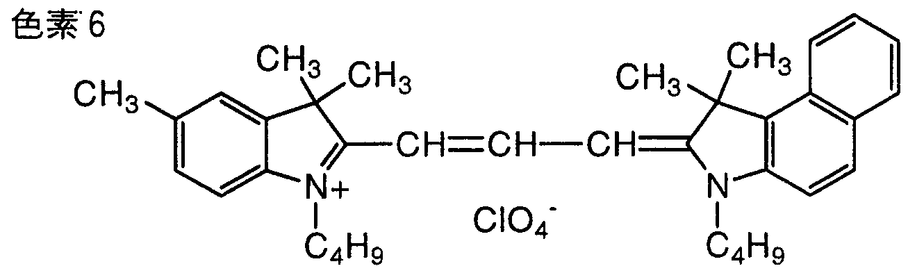
- the following dyes 1 to 12 were converted to 2,2,3,3-tetrafluoro--1-propanol (TFP) or 2,2,3,3,3,4,4,5,5-
- the coating solution was prepared by dissolving in a mixed solvent of fluoro-11-pentanol (OFP) and aliphatic saturated alcohol.
- the content of the dye in the coating solution was 1.5 wt% when TFP was used and 2.5 wt% when OFP was used.
- the coating solution was applied to a thickness of 180 OA (18 Onm) by a spin coating method on a polycarbonate resin substrate having a diameter of 120 and a thickness of 1.2 mm, followed by drying to form a dye layer.
- Spin coating using a nozzle having an inner diameter of 0. 25 mm, the discharge pressure was 0. 6 kgf ⁇ cm one 2.
- an Au reflection layer was formed on the dye layer to a thickness of 10 O by a sputtering method. Furthermore, an ultraviolet curable acrylic resin was laminated thereon by spin coating to a thickness, cured by irradiating with light to form a protective film, and an optical recording disk was produced (see FIG. 1).
- the optical recording disk thus manufactured was evaluated with DDU-100 manufactured by Pulstec. As a result, the optical recording disk of Example 1 had a recording sensitivity of 6.0 OmW, a reflectivity of 69%, and a modulation factor of 75%. ⁇ Comparative Example 1>
- a dye layer was formed in the same manner as in Example except that Dye 1 was used as the dye and the solvent of the coating solution was TFP 100%, and an optical recording disk was produced. And it evaluated similarly to the Example. The results are shown in Table 1.
- Dye layer was formed in the same manner as in Example 1, except that Dye 1 was used as the dye, and the solvent of the coating solution was a mixed solvent of TFP and methyl sorb (weight ratio: 95: 5). A disc was prepared. And it evaluated similarly to the Example. The results are shown in Table 1. When this solvent was used, the filter was clogged, the discharge pressure increased, etc., and the film thickness fluctuated, resulting in a portion that was not coated, making it impossible to perform continuous coating on 350 sheets. Further, the average amount of the dye solution used per sheet was larger than that in the example.
- the dye layer was formed in the same manner as in Example 1 except that Dye 1 was used as the dye, and the solvent of the coating solution was a mixed solvent of TFP and Ethylse Solv (weight ratio: 93: 7). A disc was prepared. And it evaluated similarly to the Example. The results are shown in Table 1. When this solvent was used, the filter was clogged, the discharge pressure increased, etc., and the film thickness fluctuated, and a portion where no coating was performed occurred, making it impossible to perform continuous coating on 500 sheets. Further, the average amount of the dye solution used per sheet became larger than that in the example. The invention's effect
- the yield can be improved, the loss of the dye solution can be reduced, and the cost can be reduced in the manufacturing process of the optical recording medium. Furthermore, even if the coating is performed continuously, filter clogging does not occur, the variation in film thickness is small, and a product of stable quality can be obtained.
Landscapes
- Chemical & Material Sciences (AREA)
- Organic Chemistry (AREA)
- Engineering & Computer Science (AREA)
- Manufacturing & Machinery (AREA)
- Manufacturing Optical Record Carriers (AREA)
- Optical Record Carriers And Manufacture Thereof (AREA)
- Thermal Transfer Or Thermal Recording In General (AREA)
Description
明 細 書
光記録媒体の製造方法および光記録媒体 技術分野
本発明は、 色素溶液を塗布して色素膜を形成する光記録媒体の製造方法および 光記録媒体に関する。 背景技術
近年、 大容量情報担持媒体として、 追記型や書き換え可能型などの各種光記録 ディスクが注目されている。
このような光記録ディスクの中に、 色素を主成分とする色素膜を記録層として 用いるものがある。 また、 構造的には、 従来、 汎用されている色素膜からなる記 録層上に空気層を設けたいわゆるエアーサンドイッチ構造のものや、 コンパクト ディスク (C D) 規格に対応した再生が可能なものとして色素膜からなる記録層 に反射層を密着して設けた構造のものが提案されている (日経エレクトロニクス 1 9 8 9年 1月 2 3日号、 N o . 4 6 5、 P 1 0 7、 社団法人近畿化学協会機能 性色素部会、 1 9 8 9年 3月 3日、 大阪科学技術センタ一、 PROCEEDINGS SPIE-T HE INTERNATIONAL SOCIETY FOR OPTICAL ENGINEERING VOL. 1078 PP80-87, " OPT I CAL DATA STORAGE TOPICAL MEETING" 17-19, IANUARY 1989 LOS ANGELES等) 。 このような記録層に用いる色素としては、 シァニン色素、 フタロシアニン色素、 ァゾ金属色素等が用いられている。
これらの色素は、 通常、 有機溶剤に溶解し、 スピンコート法により、 記録膜を 設層している。 スピンコート法は、 簡便で、 大きな設備を必要としない点で優れ た製造方法である。 しかし、 スピンコート法では、 歩留まりが悪いという問題が ある。 色素は高価なので、 その使用効率が悪いと、 そのロスによって、 コストア
ップしてしまう。
色素溶液の溶媒は、 色素を十分に溶解することが必要であり、 従来、 ケトアル コール系、 ケトン系、 アルコール系、 炭化水素系、 エステル系、 ェ一テル系、 セ 口ソルブ系、 ハロゲン化アルキル系、 ハロゲン化アルコール系等が用いられてい る。 中でも、 ハロゲン化アルコール、 特にフッ素化アルコールは色素の溶解性が 高く、 好ましく用いられている。
色素膜を塗布する場合、 色素溶液の使用効率を高くするためには、 その吐出量 を少なくすればよい。 しかしながら、 ある一定量以下になると、 基板表面を完全 に覆うことができず、 光記録ディスクの外周部に楔型の形をした塗布されない部 分が生じたりして塗布欠陥が生じてしまう。 前記の溶媒を用いてスピンコートし た場合、 このような塗布欠陥のない高品質の光記録媒体を得るためには多量の吐 出量が必要であり、 色素溶液のロスが多く、 使用効率が悪い。 また、 連続塗布す ると、 塗布液をノズルから吐出する際の吐出圧力が高くなり、 膜厚が変動したり、 塗布欠陥が生じたりしてしまうこともある。 発明の開示
本発明の目的は、 歩留まりが高く、 色素溶液のロスが少なく、 その使用効率が 高く、 さらには、 連続塗布しても安定した品質の製品が得られる光記録媒体の製 造方法および光記録媒体を提供することである。
上記の課題を解決するために、 本発明者らは鋭意検討した結果、 色素を非常に よく溶かす主溶剤中に、 水酸基 (一〇H基) をもつ第二の溶剤を加えることによ り、 基板との濡れ性が向上し、 色素の吐出量を低減できることを見いだし、 本発 明を完成した。
すなわち、 上記のような目的は、 下記の本発明により達成される。
( 1 ) 樹脂基板上に色素の溶液を塗布して色素膜を形成する光記録媒体の製
造方法において、
前記色素溶液の溶媒が、
テトラフルォロプロパノールおよび/またはォクタフルォロペン夕ノールと、 炭素数 1〜 4の脂肪族飽和アルコールとを混合したものであり、
この色素溶液を塗布することにより記録層を設層する光記録媒体の製造方法。 (2) 前記脂肪族飽和アルコールの含有量が、 前記溶媒の 0. 5~40wt% である上記 (1) の光記録媒体の製造方法。
( 3 ) 前記色素のテトラフルォロプロパノ一ルおよび Zまたはォク夕フルォ 口ペン夕ノールに対する 25 での溶解度が 0. 3wt%以上である上記 (1) ま たは (2) の光記録媒体の製造方法。
(4) 上記 (1) 〜 (3) のいずれかの光記録媒体の製造方法により製造さ れた光記録媒体。 図面の簡単な説明
図 1は、 本発明の光記録ディスクの一例を示す部分断面図である。
図 2は、 本発明の光記録ディスクの他の一例を示す部分断面図である。 作用
本発明の光記録媒体の製造方法は、 テトラフルォロプロパノールおよび また はォクタフルォロペンタノールと、 炭素数 1〜4の脂肪族飽和アルコールとの混 合溶媒を用いた色素溶液を、 樹脂基板上に塗布することにより記録層を設層する ものである。
本発明で用いる色素溶液の混合溶媒では、 テトラフルォロプロパノールおよび /またはォク夕フルォロペン夕ノールが主溶剤である。 これらは、 従来用いられ ている溶剤であり、 前述したように、 色素の溶解性は高いが、 単独では色素溶液
の使用効率が悪いという問題がある。
これに、 _〇H基をもつ低分子量の第二の溶剤を加えることにより、 色素の高 い溶解性を保ったまま、 溶液の表面張力が低下し、 基板との濡れ性が向上するの で、 色素溶液の吐出量を低減しても塗布欠陥が生じることがなく、 基板表面を完 全に、 かつ、 均一に覆うことができる。 その結果、 色素の使用効率が高くなるの で、 コストダウンができる。
また、 この混合溶媒を用いると、 連続塗布しても、 フィルター詰まり、 吐出圧 力の上昇等が生じることがなく、 膜厚変動も非常に小さい。 つまり、 連続塗布し ても、 従来のものより少ない色素の使用量で、 高品質のディスクを安定して製造 することができる。
また、 スピンコートする際、 弱い吐出圧力で色素溶液を吐出することができ、 ノズルの形状を細くすることができ、 その結果として色素溶液の使用量を低減で きるメリットが生じる。
なお、 色素溶液の溶媒に 2種以上の混合溶剤を用いることは、 既に開示されて いる。
特開平 4一 3 3 7 5 3 8号公報には、 R OM領域を有する追記型 C Dに関して、 フッ素化アルコール (2 , 2 , 3 , 3—テトラフロロプロパノール) と 2—メト キシエタノールとの混合溶媒を用いた色素溶液をスピンコートして記録層を設け る光記録媒体の製造方法が開示されている。 これによつて、 R OM領域と追記領 域とを塗り分けすることなく色素層を成膜できると記載されている。 しかし、 こ の溶媒では結晶化しやすく、 連続塗布することが難しい。 また、 色素溶液の使用 効率の向上は極めて低い。
また、 特開平 4— 3 3 2 9 3 0号公報には、 樹脂基板を実質的に溶解しない溶 媒と樹脂基板を溶解する溶媒との混合溶媒を用いた色素溶液を塗布して記録層を 形成する光記録媒体の製造方法が開示されている。 しかし、 基板を溶解する溶剤
を用いているため、 この混合溶媒を用いて記録層を形成すると基板が溶解してし まう可能性がある。 通常、 わずかでも溶剤が基板を溶解すると、 記録媒体にした ときのノイズ部分が増え、 エラーが多くなつてしまう。 発明を実施するための最良の形態
以下、 本発明の具体的構成について詳細に説明する。
本発明に使用する色素は、 テトラフルォロプロパノールおよび またはォクタ フルォロペン夕ノールに 2 5 で 0 . 3 wt %以上、 好ましくは 0 . 3〜8 wt %溶 解するものであれば何ら限定されない。 そして、 その具体的な例としては、 シァ ニン色素、 フタロシアニン色素、 ァゾ金属錯体色素、 ホルマザン色素、 口一ダミ ン色素、 ァゾ色素、 卜リフエニルメタン系色素等がある。 なかでも、 シァニン色 素、 フタロシアニン色素の使用は好ましく、 シァニン色素としてはインドレニン 系シァニン色素が好ましい。 インドレニン系シァニン色素は、 金属錯体クェンチ ヤーと混合することが好ましい。 フタロシアニン色素としては E P 6 7 5 4 8 9 号等に記載の化合物が好ましく用いられる。 C D— R用の色素としてはペンタメ チンインドレニン系シァニン色素やフタロシアニン色素が好ましく用いられ、 D VD—R用の色素としてはトリメチンインドレニン系シァニン色素が好ましく用 いられる。 インドレニン系シァニン色素は、 クェンチヤ一として N i、 C uジチ オレン金属錯体ァ二オンゃァゾ金属錯体ァ二オンを対イオンとして有するものも 好ましく使用される。 また、 ァゾ金属錯体色素も好ましい。 ァゾ金属錯体色素と しては、 例えば、 特願平 8— 2 8 6 4 6号公報、 特願平 8— 1 6 6 8 8 5号公報、 特願平 8 - 2 0 4 3 4 0号公報、 特顧平 9一 2 1 0 1 6号公報、 特願平 2— 6 8 9 6 6号公報等に記載されているものが挙げられる。 ァゾ金属錯体色素は、 D V D— R用に用いることが好ましい。
これらの色素は 1種のみを用いても 2種以上を併用してもよい。
また、 クェンチヤ一としては、 アミン系色素、 ジチォベンジル金属錯体、 ベン ゼンジチオール金属錯体等がある。 クェンチヤ一は、 上記色素と混合して用いて もよいが、 色素の対イオンとして用いることが好ましい。
本発明で色素塗布溶液の溶媒に使用する有機溶剤は、 2, 2, 3, 3—テトラ フルオロー 1—プロパノール (TFP) および Zまたは 2, 2, 3, 3, 4, 4, 5, 5—ォクタフルオロー 1一ペンタノ一ル (OFP) と、 炭素数 1〜4の脂肪 族飽和アルコールとを混合したものを用いる。 TFPと OFPは任意の割合で混 合してもよい。
脂肪族飽和アルコールの炭素数は 1〜4である。 脂肪族飽和アルコールの炭素 鎖は分岐を有していてもよい。
脂肪族飽和アルコールとしては、 具体的には、 メタノール、 エタノール、 1一 プロパノール、 2 _プロパノール、 ブタノ一ル、 2—ブタノ一ル等が挙げられ、 これらから適宜選択すればよい。 特に、 メタノール、 エタノール、 1—プロパノ —ル、 2—プロパノールが好ましい。 脂肪族飽和アルコールは 2種以上を併用し てもよい。
テトラフルォロプロパノールおよび Zまたはォクタフルォロペンタノ一ルと、 脂肪族飽和アルコールとの混合比は、 脂肪族飽和アルコールの重量比が 0. 5〜 40wt%、 さらには 1~30wt%が好ましい。 40wt%を超えると、 色素の溶解 性が悪くなり、 結晶化しやすくなる。 0. 5wt%未満では、 色素の吐出量が低減 されにくくなつてくる。
スピンコート法は、 通常の方法を用いればよい。 必要に応じて回転数を制御し て塗膜を乾燥させる。 ただし、 色素溶液を吐出させるときには、 1500rpm以 下の回転数にすることが好ましい。 このようにして形成される記録層の厚さは、 目的とする反射率に応じて適宜設定されるものであるが、 通常、 1000〜30 0 OA (100〜30 Onm) 程度である。 また、 スピンコートした後、 80°C以
下の乾燥工程を入れてもよい。
なお、 塗布液における色素含有量は、 好ましくは 0. 3〜10wt%、 さらに好 ましくは 0. 4〜5wt%とするのがよい。 色素を 2種以上併用する場合も、 合計 で前記範囲の含有量とすればよい。
塗布液には、 適宜、 バインダー、 分散剤、 安定剤等を含有させてもよい。
このような色素膜を記録層として基板上に有する光記録ディスクの一例を図 1 に示す。 図 1は、 部分断面図である。
図 1に示される光記録ディスク 1は、 記録層上に反射層を密着して有する CD 規格に対応した再生が可能な密着型光記録ディスクである。 図示のように、 光記 録ディスク 1は、 基板 2表面に前記のような色素を主成分とする記録層 3を有し、 記録層 3に密着して、 反射層 4、 保護膜 5を有する。
基板 2は、 ディスク状のものであり、 基板 2の裏面側からの記録および再生を 可能とするために、 記録光および再生光 (波長 600〜90 Onm程度、 特に波長 630〜 79 Onm程度の半導体レーザー光) に対し、 実質的に透明 (好ましくは 透過率 88%以上) な樹脂あるいはガラスを用いて形成するのがよい。 また、 そ の大きさは、 直径 64〜 200誦程度、 厚さ 6〜1. 2mm程度にする。
基板 2の記録層 3形成面には、 図 1に示すように、 トラッキング用のグループ 23が形成される。 グループ 23は、 スパイラル状の連続型グループであること が好ましく、 深さは 0. 08〜0. 25 m 、 幅は 0. 20〜0. 60 m 、 グ ル一ブピッチは 0. 7〜1. 7 mであることが好ましい。 グループをこのよう な構成とすることにより、 グループ部の反射レベルを下げることなく、 良好なト ラッキング信号を得ることができる。 特にグルーブ幅を規制することは重要であ り、 グループ幅を 0. 2 θ ΐη未満とすると、 十分な大きさのトラッキング信号 が得られにくく、 記録時のトラッキングのわずかなオフセットによって、 ジッ夕 一が大きくなりやすい。 また、 グループ幅が大きくなると、 波形ひずみが生じや
すくなる。 これらの値は、 記録再生するレーザ一の波長により適宜選ぶことがで さる。
基板 2は、 材質的には、 樹脂を用いることが好ましく、 ポリカーボネート樹脂、 アクリル樹脂、 アモルファスポリオレフイン、 TPX、 ポリスチレン系樹脂等の 各種熱可塑性樹脂が好適である。 そして、 このような樹脂を用いて射出成形等の 公知の方法に従って製造することができる。 ダル一ブ 23は、 基板 2の成形時に 形成することが好ましい。 なお、 基板 2製造後、 2 Ρ法等によりダル一ブ 23を 有する樹脂層を形成してもよい。 また、 場合によってはガラス基板を用いてもよ い。
記録層 3は、 前述の通り、 通常のスピンコート法で設層すればよい。 その厚さ は、 乾燥膜厚で、 1000〜3000A (100〜300mn) 、 特に 1300〜 3000Α (130〜300ηιιι) とすることが好ましい。 この範囲外では反射率 が低下して、 良好な再生を行うことが難しくなる。
このようにして形成される記録層 3は、 その記録光および再生光波長における 消衰係数 (複素屈折率の虚部) kは、 0. 02〜0. 2であることが好ましい。 kが 0. 02未満となると、 記録層の吸収率が低下し、 通常の記録パワーで記録 を行うことが困難である。 kが 0. 2を超えると、 反射率が非常に低くなり、 良 好な再生を行うことが困難である。 また、 記録層 3の屈折率 (複素屈折率の実 部) nは、 1. 8〜2. 6であることが好ましい。 nが 1. 8未満となると、 反 射率が低下し、 また、 再生信号が小さくなり、 良好な再生が困難となる傾向にあ る。 nの上限は特に制限はないが、 色素化合物の合成上の都合等から、 通常 2. 6程度である。
なお、 記録層の nおよび kは、 所定の透明基板上に記録層を例えば 40〜10 Onm程度の厚さに実際の条件にて設層して測定用サンプルを作製し、 次いで、 こ の測定用サンプルの基板を通しての反射率あるいは記録層側からの反射率を測定
することによって求める。 この場合、 反射率は、 記録再生光波長を用いて鏡面反 射 (5° 程度) にて測定する。 また、 サンプルの透過率を測定する。 そして、 こ れらの測定値から、 例えば、 共立全書 「光学」 石黒浩三 P. 168〜178に準じ て n、 kを算出すればよい。
図 1に示されるように、 記録層 3上には、 直接密着して反射層 4が設層される。 反射層 4としては、 Au、 Ag、 A 1等の高反射率金属ないし合金を用いるのが よい。 反射層 4の厚さは 50 OA ( 50 nm) 以上であることが好ましく、 蒸着、 スパッ夕等により設層すればよい。 また、 厚さの上限に特に制限はないが、 コス ト、 生産作業時間等を考慮すると、 120 OA (12 Onm) 程度以下であること が好ましい。 これにより、 反射層 4単独での反射率は 90 %以上であり、 媒体の 未記録部の基板を通しての反射率は十分である。
図 1に示されるように、 反射層 4上には、 保護膜 5が設層される。 保護膜 5は、 例えば紫外線硬化樹脂等の各種樹脂材質から、 通常は、 0. 5〜100 / m程度 の厚さ設層すればよい。 保護膜 5は、 層状であってもシート状であってもよい。 保護膜 5は、 スピンコート、 グラビア塗布、 スプレーコート、 デイツピング等の 通常の方法により形成すればよい。
また、 図 2のように張り合わせて、 両面ディスクにしてもよい。 このような光 記録ディスクの一例を図 2に示す。 図 2は、 部分断面図である。
図 2に示される光記録ディスク 10は、 デジタルビデオディスク (DVD) 規 格に対応した光記録ディスクであり、 光記録ディスク 1と同様な構造のディスク の保護膜 15および保護膜 25同士を接着剤で貼り合わせて形成する。 接着剤は 熱硬化性樹脂等を用いればよく、 接着剤層 50の厚さは 10〜20 O m程度で ある。 この場合の基板一枚当たりの厚さは 0. 6mm程度であり、 グループ 123 を有するこの基板 12上に、 図 1と同様の記録層 13、 反射層 14、 保護膜 15 を順次形成し、 一方、 グループ 223を有する基板 22上にも同様に、 記録層 2
3、 反射層 24、 保護膜 25を形成し、 上述のように貼り合わされて得られる。 このものの基板は前記した図 1のもの (光記録ディスク 1) に準じるが、 ダル ーブの深さは 600〜200 OA (60〜20 Onm) 、 幅 0. 2〜0. 5 m 、 グループピッチは 0. 6〜1. 0 imであることが好ましい。
また、 記録層の厚さは 1000〜3000A (100〜300nm) が好ましく、 635nmにおける複素屈折率は n= 1. 8〜2. 6、 k = 0. 02〜0. 20で あることが好ましい。
このような構成の光記録ディスク 1 (CD規格対応) に記録ないし追記を行う には、 例えば 78 Ornnの記録光を、 基板 2を通してパルス状に照射し、 照射部の 光反射率を変化させる。 なお、 記録光を照射すると、 記録層 3が光を吸収して発 熱し、 同時に基板 2も加熱される。 この結果、 基板 2と記録層 3との界面近傍に おいて、 色素等の記録層材質の融解や分解が生じ、 記録層 3と基板 2との界面に 圧力が加わり、 グループの底面や側壁を変形させることがある。
また、 光記録ディスク 10 (DVD規格対応) に記録ないし追記を行うには、 635ηπι程度の短波長で同様にして記録し、 650 nm程度の波長で再生を行う。 本発明の光記録媒体は、 図示例のような密着型の光記録媒体に限らず、 色素を 含有する記録層を有するものであれば、 いずれであってもよい。 このようなもの としては、 エア一サンドイッチ構造のピット形成型光記録媒体等が挙げられ、 本 発明を適用することによって、 同様の効果が得られる。 実施例
以下、 本発明の具体的実施例を示し、 本発明をさらに詳細に説明する。
<実施例 >
表 1に示すように、 下記の色素 1〜12を、 2, 2, 3, 3—テトラフルォロ — 1—プロパノール (TFP) または 2, 2, 3, 3, 4, 4, 5, 5—才クタ
フルオロー 1一ペン夕ノール (OFP) と脂肪族飽和アルコールとの混合溶剤に 溶解して塗布液を調製した。 塗布液における色素の含有量は、 TFPを使用した 場合 1. 5wt%、 OFPを使用した場合 2. 5wt%とした。

色素 2

色素 3

色素 4


色素

CH3(CH2)3CHCH20(CH2)3N+H3
C2H5
色素 8

色素 9


: 2+ ヽ


直径 120画、 厚さ 1. 2 mmのポリ力一ボネート樹脂基板上に、 スピンコート 法により、 前記塗布液を 180 OA (18 Onm) の厚さに塗布、 乾燥し、 色素層 を形成した。 スピンコートは、 内径 0. 25 mmのノズルを使用し、 吐出圧力は 0. 6 kgf · cm一2とした。
1000枚連続して塗布を行ったところ、 フィルター詰まり、 吐出圧力上昇等 は起こらなかった。
このときの 1枚当たりの色素溶液の平均使用量を、 使用した液量と塗布したデ イスクの枚数 (1000枚) とから算出した。 その結果を表 1に示す。
また、 1000枚のディスクの膜厚の変動がどれくらいかも調べた。 その結果 を表 1に示す。
色素 溶媒 塗出量 フィルター ディスク
(モル比) (重量比) (g) 詰まり 特性 実施例 1 色素 1 TFP : 2-プロパノ一ノレ = 95: 5 0.30 なし <3% 良好 実施例 2 色素 2 : 色素 11 = 85 : 15 TFP :メタノーノレ = 98: 2 0.30 なし <3% 良好 実施例 3 色素 1: 色素 12 = 90: 10 TFP: 1-プロパノール = 98: 2 0.28 なし <3% 良好 実施例 4 色素 3 TFP: :エタノール = 80: 20 0.29 なし <3% 艮好 実施例 5 色素 1 : 色素 4 = 70: 30 TFP: : 1-プロパノール = 90: 10 0.27 なし <3% 艮好 実施例 6 色素 3 : 色素 5: 色素 7 = 50: 30: 20 TFP: 2-プロパノール = 95: 5 0.30 なし <3% 艮好 実施例 7 色素 8 : 色素 6 = 90 : 10 OFP : 2-プロパノーノレ = 90: 10 0.32 なし <3% 良好 実施例 8 色素 6 : 色素 7 = 70: 30 OFP : 2-プロパノール = 98: 2 0.34 なし <3% 良好 実施例 9 色素 9 OFP : フタノ一ノレ = 93: 7 0.33 なし <3% 好 実施例 10 色素 10 : 色素 3 = 90: 10 OFP :ブタノール = 85: 15 0.35 なし <3% 良好 比較例 1 色素 1 TFP 0.45 あり * 比較例 2 色素 1 TFP :メチルセ口ソルブ = 95: 5 0.50 . あり * 比較例 3 色素 1 TFP :ェチルセ口ソルブ = 93: 7 0.50 あり *
* 100枚以下
次いで、 この色素層上に、 A u反射層をスパッタ法により 1 0 O の厚さに形 成した。 さらに、 この上に、 紫外線硬化型のアクリル樹脂をスピンコート法によ り膜厚 に積層し、 光照射して硬化させて保護膜を形成し、 光記録ディスク を作製した (図 1参照) 。
このようにして作製した光記録ディスクをパルステック製 D D U— 1 0 0 0で 評価した。 その結果、 実施例 1の光記録ディスクで記録感度 6 . O mW、 反射率 6 9 %、 変調度 7 5 %であり、 他のものもこれと同等で、 良好な特性が得られた。 <比較例 1〉
色素には色素 1を用い、 塗布液の溶媒を T F P 1 0 0 %とした他は実施例と同 様にして色素層を形成し、 光記録ディスクを作製した。 そして、 実施例と同様に 評価した。 その結果を表 1に示す。
<比較例 2 >
色素には色素 1を用い、 塗布液の溶媒を T F Pとメチルセ口ソルブとの混合溶 剤 (重量比 9 5 : 5 ) とした他は実施例 1と同様にして色素層を形成し、 光記録 ディスクを作製した。 そして、 実施例と同様に評価した。 その結果を表 1に示す。 この溶媒を使用すると、 フィルタ一詰まり、 吐出圧力の上昇等が起こって膜厚 が変動し、 塗布されない部分が生じて 3 5 0枚で連続塗布ができなくなった。 ま た、 1枚当たりの色素溶液の平均使用量は実施例よりも大きくなった。
<比較例 3 >
色素には色素 1を用い、 塗布液の溶媒を T F Pとェチルセ口ソルブとの混合溶 剤 (重量比 9 3 : 7 ) とした他は実施例 1と同様にして色素層を形成し、 光記録 ディスクを作製した。 そして、 実施例と同様に評価した。 その結果を表 1に示す。 この溶媒を使用すると、 フィルタ一詰まり、 吐出圧力の上昇等が起こって膜厚 が変動し、 塗布されない部分が生じて 5 0 0枚で連続塗布ができなくなった。 ま た、 1枚当たりの色素溶液の平均使用量は実施例よりも大きくなつた。
発明の効果
本発明によれば、 光記録媒体の製造工程において、 歩留まりを向上し、 色素溶 液のロスを低減することができ、 コストダウンができる。 さらには、 連続塗布し てもフィルター詰まり等は起こらず、 膜厚の変動が小さく、 安定した品質の製品 が得られる。
Claims
1 . 樹脂基板上に色素の溶液を塗布して色素膜を形成する光記録媒体の製造方 法において、
前記色素溶液の溶媒が、
テトラフルォロプロパノールおよび/またはォクタフルォロペン夕ノールと、 炭素数 1〜 4の脂肪族飽和アルコールとを混合したものであり、
この色素溶液を塗布することにより記録層を設層する光記録媒体の製造方法。
2 . 前記脂肪族飽和アルコールの含有量が、 前記溶媒の 0 . 5〜4 0 wt %であ る請求の範囲第 1項記載の光記録媒体の製造方法。
3 . 前記色素のテトラフルォロプロパノールおよび/またはォクタフルォロぺ ン夕ノールに対する 2 5 °Cでの溶解度が 0 . 3 wt %以上である請求の範囲第 1項 または第 2項記載の光記録媒体の製造方法。
4 . 請求の範囲第 1項〜第 3項のいずれかに記載の光記録媒体の製造方法によ り製造された光記録媒体。
Priority Applications (1)
| Application Number | Priority Date | Filing Date | Title |
|---|---|---|---|
| EP99919670A EP1014354A4 (en) | 1998-05-27 | 1999-05-25 | METHOD FOR PRODUCING OPTICAL RECORDING MEDIUM, AND OPTICAL RECORDING MEDIUM |
Applications Claiming Priority (2)
| Application Number | Priority Date | Filing Date | Title |
|---|---|---|---|
| JP10/162940 | 1998-05-27 | ||
| JP16294098A JP3286249B2 (ja) | 1998-05-27 | 1998-05-27 | 光記録媒体の製造方法 |
Publications (1)
| Publication Number | Publication Date |
|---|---|
| WO1999062064A1 true WO1999062064A1 (en) | 1999-12-02 |
Family
ID=15764149
Family Applications (1)
| Application Number | Title | Priority Date | Filing Date |
|---|---|---|---|
| PCT/JP1999/002720 Ceased WO1999062064A1 (en) | 1998-05-27 | 1999-05-25 | Method for producing optical recording medium and optical recording medium |
Country Status (5)
| Country | Link |
|---|---|
| US (1) | US6383722B1 (ja) |
| EP (1) | EP1014354A4 (ja) |
| JP (1) | JP3286249B2 (ja) |
| TW (1) | TW432382B (ja) |
| WO (1) | WO1999062064A1 (ja) |
Cited By (1)
| Publication number | Priority date | Publication date | Assignee | Title |
|---|---|---|---|---|
| WO2001028965A1 (fr) * | 1999-10-22 | 2001-04-26 | Daikin Industries, Ltd. | Composition de fluoroalcool |
Families Citing this family (16)
| Publication number | Priority date | Publication date | Assignee | Title |
|---|---|---|---|---|
| JP4702730B2 (ja) * | 1999-12-02 | 2011-06-15 | 株式会社林原生物化学研究所 | スチリル色素 |
| JP4702731B2 (ja) * | 1999-12-17 | 2011-06-15 | 株式会社林原生物化学研究所 | シアニン色素 |
| WO2002050210A1 (en) * | 2000-12-19 | 2002-06-27 | Kabushiki Kaisha Hayashibara Seibutsu Kagaku Kenkyujo | Light absorbing agent |
| US20040063843A1 (en) * | 2002-07-19 | 2004-04-01 | Honeywell International, Inc. | Coating solutions |
| JPWO2004015703A1 (ja) * | 2002-08-09 | 2005-12-02 | ソニー株式会社 | 光ディスク |
| WO2005072975A1 (en) * | 2004-01-30 | 2005-08-11 | Ricoh Company, Ltd. | Optical recording medium, and, method and apparatus for optical recording and reproducing using optical recording medium |
| JP2005310272A (ja) * | 2004-04-21 | 2005-11-04 | Tdk Corp | 塗布液、光記録媒体及びその製造方法 |
| US20060144285A1 (en) * | 2004-12-30 | 2006-07-06 | Honeywell International, Inc. | Fluorine-containing coatings |
| JP2006289877A (ja) * | 2005-04-14 | 2006-10-26 | Toshiba Corp | 情報記憶媒体、再生方法及び記録方法 |
| JP2006305920A (ja) * | 2005-04-28 | 2006-11-09 | Tdk Corp | 光記録材料、光記録材料溶液並びに光記録媒体及びその製造方法 |
| CN101176153A (zh) * | 2005-05-17 | 2008-05-07 | 松下电器产业株式会社 | 多层信息记录介质及其制造方法 |
| JP2007056114A (ja) * | 2005-08-23 | 2007-03-08 | Tdk Corp | 色素材料、並びに、これを用いた光記録媒体及びその製造方法 |
| JP2007276343A (ja) * | 2006-04-10 | 2007-10-25 | Fujifilm Corp | 光記録媒体、可視情報記録方法、及び色素化合物の利用方法 |
| EP2045806A3 (en) * | 2007-10-01 | 2009-05-06 | Clariant International Ltd | Use of indolinium diazamethine cations for optical data recording |
| US20100093983A1 (en) * | 2007-05-09 | 2010-04-15 | Klein Cedric | Use of indolimium diazamethine cations for optical data recording |
| WO2008154771A1 (en) * | 2007-06-20 | 2008-12-24 | Dongguan Memtech Electronic Products Co., Ltd | An injection molding plastic sheet with 3d texture and its manufacturing process |
Citations (1)
| Publication number | Priority date | Publication date | Assignee | Title |
|---|---|---|---|---|
| JPH048585A (ja) * | 1990-04-26 | 1992-01-13 | Fuji Photo Film Co Ltd | 情報記録媒体の製造方法 |
Family Cites Families (13)
| Publication number | Priority date | Publication date | Assignee | Title |
|---|---|---|---|---|
| JPH0798421B2 (ja) * | 1987-06-09 | 1995-10-25 | 富士写真フイルム株式会社 | 光情報記録媒体 |
| JP2588407B2 (ja) * | 1987-08-20 | 1997-03-05 | 富士写真フイルム株式会社 | 光学的情報記録媒体 |
| US5182186A (en) * | 1987-09-29 | 1993-01-26 | Fuji Photo Film Co., Ltd. | Optical information recording medium |
| JPH023452A (ja) * | 1988-06-14 | 1990-01-09 | Fuji Photo Film Co Ltd | 色素溶液組成物および情報記録媒体の製造方法 |
| DE69033550T2 (de) | 1989-03-03 | 2001-01-18 | Tdk Corp., Tokio/Tokyo | Medium für optische Datenspeicherung |
| US5274623A (en) * | 1990-07-19 | 1993-12-28 | Fuji Photo Film Co., Ltd. | Information recording medium having high modulation degree |
| JP3197287B2 (ja) | 1991-05-08 | 2001-08-13 | 三井化学株式会社 | 光記録媒体の製造方法 |
| JPH04337538A (ja) | 1991-05-14 | 1992-11-25 | Ricoh Co Ltd | 光記録媒体の製造方法及び光記録媒体 |
| JPH05114178A (ja) * | 1991-10-22 | 1993-05-07 | Ricoh Co Ltd | 光記録媒体の製造方法及び光記録媒体 |
| JP3334721B2 (ja) | 1992-02-17 | 2002-10-15 | 株式会社リコー | 光記録媒体及びその製造方法 |
| JPH05258346A (ja) * | 1992-03-11 | 1993-10-08 | Canon Inc | 光学的記録媒体及びその製造方法 |
| US5858613A (en) * | 1996-01-23 | 1999-01-12 | Tdk Corporation | Optical recording medium |
| US5948593A (en) * | 1996-07-29 | 1999-09-07 | Mitsui Chemicals, Inc. | Optical recording medium |
-
1998
- 1998-05-27 JP JP16294098A patent/JP3286249B2/ja not_active Expired - Fee Related
-
1999
- 1999-05-25 EP EP99919670A patent/EP1014354A4/en not_active Withdrawn
- 1999-05-25 WO PCT/JP1999/002720 patent/WO1999062064A1/ja not_active Ceased
- 1999-05-26 US US09/320,509 patent/US6383722B1/en not_active Expired - Fee Related
- 1999-05-26 TW TW088108676A patent/TW432382B/zh not_active IP Right Cessation
Patent Citations (1)
| Publication number | Priority date | Publication date | Assignee | Title |
|---|---|---|---|---|
| JPH048585A (ja) * | 1990-04-26 | 1992-01-13 | Fuji Photo Film Co Ltd | 情報記録媒体の製造方法 |
Cited By (1)
| Publication number | Priority date | Publication date | Assignee | Title |
|---|---|---|---|---|
| WO2001028965A1 (fr) * | 1999-10-22 | 2001-04-26 | Daikin Industries, Ltd. | Composition de fluoroalcool |
Also Published As
| Publication number | Publication date |
|---|---|
| EP1014354A1 (en) | 2000-06-28 |
| JP3286249B2 (ja) | 2002-05-27 |
| JPH11339334A (ja) | 1999-12-10 |
| EP1014354A4 (en) | 2008-05-21 |
| TW432382B (en) | 2001-05-01 |
| US6383722B1 (en) | 2002-05-07 |
Similar Documents
| Publication | Publication Date | Title |
|---|---|---|
| US5075147A (en) | Method for optically recording information and information recorded medium | |
| JP3286249B2 (ja) | 光記録媒体の製造方法 | |
| JP2002367227A (ja) | 光情報記録媒体 | |
| JP2699120B2 (ja) | 情報記録媒体および光情報記録方法 | |
| EP1069556B1 (en) | Optical information recording medium | |
| JP2657579B2 (ja) | 光情報記録媒体 | |
| JP3673963B2 (ja) | 光情報記録媒体 | |
| JP3482481B2 (ja) | 光情報記録媒体 | |
| JPH048585A (ja) | 情報記録媒体の製造方法 | |
| JP2732314B2 (ja) | 光情報記録方法および情報記録媒体 | |
| CN100370532C (zh) | 光信息记录介质 | |
| US20030161987A1 (en) | Optical recording medium | |
| JP2002358658A (ja) | 光記録媒体およびその光記録方法 | |
| JP4060543B2 (ja) | 光記録媒体 | |
| JP2604273B2 (ja) | 光情報記録方法 | |
| JP3883277B2 (ja) | 光記録媒体およびその製造方法 | |
| JP3177291B2 (ja) | 光記録媒体 | |
| JP3896402B2 (ja) | 光情報記録媒体の製造方法及び光情報記録媒体 | |
| JP2827005B2 (ja) | シアニン系色素 | |
| JP2001307375A (ja) | 光情報記録媒体及び光情報記録再生方法 | |
| JP2000276787A (ja) | 光情報記録媒体及びその製造方法 | |
| JP2002362030A (ja) | 光記録媒体及びこれを用いる光記録方法 | |
| JPH0476836A (ja) | 情報記録媒体及びその製造方法 | |
| JP2005267668A (ja) | 光記録媒体及びその製造方法 | |
| JP2003173567A (ja) | 光記録媒体及び記録方法 |
Legal Events
| Date | Code | Title | Description |
|---|---|---|---|
| AL | Designated countries for regional patents |
Kind code of ref document: A1 Designated state(s): AT BE CH CY DE DK ES FI FR GB GR IE IT LU MC NL PT SE |
|
| WWE | Wipo information: entry into national phase |
Ref document number: 1999919670 Country of ref document: EP |
|
| 121 | Ep: the epo has been informed by wipo that ep was designated in this application | ||
| WWP | Wipo information: published in national office |
Ref document number: 1999919670 Country of ref document: EP |