再生式製版 ·印刷方法および製版 ·印刷装置
技術分野
本発明は、 再生式製版 ·印刷方法および製版 ·印刷装置に関し、 詳しくは、 作 業が大幅に効率化され、 かつ、 印刷時の汚れを抑制し安定して高品質の画像を提 明
供できる再生式の製版 ·印刷方法および製版 ·印刷装置に関する。
田 背景技術
従来より、 平版印刷機を利用した製版方法、 すなわち、 印刷機上製版方法は公 知である。 例えば、 特開昭 1 1一 2 1 6 8 3 5には、 本出願人の提案による改良 された印刷機上製版方法が記載されている。 上記の印刷機上製版方法は、 版胴、 ブランケット胴およぴ圧胴から成る印刷部を備えた平版印刷機上において、 ( A ) 版胴上に固定した画像露光済み感光性平版印刷版上にそれに接触配置された製版 処理剤供給ローラーから製版処理剤を供給し、 次いで、 (B ) 版胴とブランケッ ト胴を接触回転させて上記の感光性平版印刷版上に物理的刺激を与えることによ り画像を形成させる、 感光性平版印刷版の印刷機上製版方法である。
上記の方法は、 ブランケット胴と圧胴を離間状態にし、 更に、 圧胴への紙の送 給を停止した状態とした後、 上記 (B ) の操作を行うことを特徴とする方法であ る。 斯かる方法は、 版胴上に画像露光済み感光性平版印刷版を固定して製版を行 なった後に引き続き印刷を行う方法であり、 紙の無駄 (損紙) の低減おょぴ製版 処理剤 (印刷インク、 湿し水など) へのゴミの混入低減を図ったものである。 しかしながら、 上記の特開昭 1 1— 2 1 6 8 3 5においては、 現像方法として、 印刷機上において湿し水を使用して現像する方法が開示されているのみである。 また、 印刷後の印刷版を再生して使用することについては全く記載されていない。
また、 日本特許第 3 122717号 (EP 802457A1 ) には、 感光性組 成物として光照射により疎水性に性質が変ィ匕する親水性ェマルジヨンを使用し、 溶融法により印刷機上で露光 ·現像する方法が開示されているが、 更に耐刷性を 改良する必要がある。 ここでは、 現像方法として、 印刷機上において湿し水を使 用して現像する方法が開示されているのみである。 更に、 印刷後の印刷版を再生 してもよいとの記載はあるが、 具体的にどの様にして界生するのがについては、 全く記載されていない。
特開平 9— 99535 (US P 5713287) には、 感光性組成物として、 レーザー照射により親水性と疎水性の性質が変わるスィツチングポリマーを使用 し、 印刷機上で画像を形成する方法が開示されているが、 更に耐刷性を改良する 必要がある。 上記の方法では、 印刷工程とは独立した現像工程は設けられていな い。
更に、 特開平 8— 52949 (US P 5816 16 1, EP 693371A 1) には、 印刷機内で、 版胴あるいは印刷版を取り外すことなく、 繰り返し印刷版に おける画像部の消去および再生を行う方法が開示されている。 しかしながら、 こ こでは、 具体的な現像および印刷法については全く記載されていない。
本発明の目的は、 従来の印刷機上製版方法を更に改良し、 作業が大幅に効率化 され、 かつ、 印刷時の汚れを抑制し安定して高品質の画像を提供できる再生式の 製版 ·印刷方法および製版 ·印刷装置を提供することにある。 発明の開示
本発明者等は、 上記課題を解決すべく鋭意検討した結果、 印刷工程とは独立の 別個の現像工程を必須とする印刷システムにおいて、 回転ドラム又はコンベア一 上で露光、 現像、 印刷、 再生を行い、 これらを繰り返すという新しい思想のプロ セスを使用することにより、 上記課題を解決できることを見出し、 本発明に到達 した。
すなわち、 本発明の第 1の要旨は、 下記の (A) 〜 (E ) の工程を順次行う再 生式製版'印刷方法において、 現像工程 (C ) と印刷工程 (D) とを独立の工程 として行い、 かつ、 同一の回転ドラム又はコンベア一上で (A) 〜 (E ) の工程 を繰り返し行うことを特徴とする再生式製版 ·印刷方法に存する。
(A) 支持体上に版剤供給機構から感光性版剤を供給塗布して、 感光性層が形成 された感光性平版印刷版を作製する感光性層塗布工程。
( B ) 露光機構により感光性平版印刷版の前記感光性層を画像露光する露光工程。
( C ) 画像露光済みの前記感光性層上に、 製版処理剤供給機構から製版処理剤を 供給して画像を形成する現像工程。
(D) 工程 (C ) で得られた画像表面にインク着肉装置おょぴ湿し装置からそれ ぞれ印刷インキ及ぴ湿し水を供給して印刷する印刷工程。
( E ) 版剤除去機構により支持体上の画像部分を除去して支持体を再生する支持 体再生工程。
また、 本発明の第 2の要旨は、 版胴、 ブランケット胴、 圧胴、 インク着肉装置 および湿し装置を有する平版印刷機と、 前記版胴上に支持体を固定するための支 持体固定手段と、 前記支持体上に版剤を供給するための版剤供給機構と、 前記支 持体上に感光性版剤を供給塗布して形成された感光性平版印刷版を画像露光する ための露光機構と、 版剤溶解液供給機構、 必要に応じて設けられる版剤剥離ロー ラー、 洗浄水供給機構、 廃液吸引機構およびエアー式乾燥機構から成る版剤除去 機構と、 上記の各要素の全体を収容するためのスライド可能な前面開放型のケー シングと、 当該ケーシングの天井部に設置された除塵フィルタ一とから主として 構成され、 前記版胴、 前記ブランケット胴および前記圧胴の各胴間は離間可能に なされ、 前記圧胴への紙の送給停止は制御可能になされ、 前記着肉装置および前 記湿し装置は前記版胴に対して離間可能になされていることを特徴とする再生式 の印刷機上製版 ·印刷装置に存する。
図面の簡単な説明
第 1図は、 本発明に係る再生式の印刷機上製版 ·印刷方法を行うための装置の 一例の概念図である。 第 2図は、 本発明に係る再生式の製版方法を行うための装 置の一例の概念図である。
発明を実施するための最良の形態
以下、 本発明の実施形態を図面に基づいて詳細に説明する。 図中、 符号 (1) はケーシング、 符号 (1 1) は除塵フィルター、 符号 (12) は排気ダクト、 符 号 (21) は版胴、 符号 (22) はブランケット胴、 符号 (23) は圧胴、 符号
(3) は支持体 (平板印刷版) 、 符号 (3 1) は支持体固定手段、 符号 (4) は 版剤供給機構、 符号 (5) は露光機構、 符号 (6) はインク着肉装置、 符号 (7) は湿し装置、 符号 (9) は光加熱式乾燥機構、 符号 (80) は製版処理剤供給機 構、 符号 (81) は版剤溶解液供給機構、 符号 (82) は版剤剥離ローラー、 符 号 (83) は洗浄水供給機構、 符号 (84) は廃液吸引機構、 符号 (8 5) はェ ァ一式乾燥機構、 符号 (86) は汚染防止トレーをそれぞれ示す。
本発明の第 1の発明は、 回転ドラム又はコンベア一上において露光、 現像、 印 刷、 再生の各々の工程を順次独立に行う方法であり、 印刷工程とは独立の現像ェ 程を有することが特徴である。
具体的には、 下記の (A) 〜 (E) の工程を順次回転ドラム又はコンベア一上 で繰り返し行う。
(A) 支持体上に版剤供給機構から感光性版剤を供給塗布して、 感光性層が形成 された感光性平版印刷版を作製する感光性層塗布工程。
(B) 露光機構により感光性平版印刷版の前記感光性層を画像露光する露光工程。
(C) 画像露光済みの前記感光性層上に、 製版処理剤供給機構から製版処理剤を 供給して画像を形成する現像工程。
(D) 工程 (C) で得られた画像表面にインク着肉装置および湿し装置からそれ
P T/肩 04144
5 ぞれ印刷ィンキ及び湿し水を供給して印刷する印刷工程。
( E ) 版剤除去機構により支持体上の画像部分を除まして支持体を再生する支持 体再生工程。
上記の様な製版'印刷方法を採用することにより、 平版印刷版の支持体を繰り返 し多数回使用可能なため、 印刷経費の大幅な削減が可能になると共に、 作業を大 幅に効率化でき、 かつ、 印刷時の汚れを抑制し、 安定して高品質の画像を提供す ることが可能となる。
本発明においては、 上述した (A) 〜 (E) の工程を順次繰り返して行う限り、 特にその方法や装置は限定されないが、 中でも、 印刷時の版胴上 (印刷機上) で 工程 (A) 〜 (E) を実施するのが、 装置がコンパクトになるという点で好まし い
第 1図は、 本発明に係る再生式の印刷機上製版 ·印刷方法を行うための装置を 示しており、 第 1図に示す装置は、 版胴 (2 1) 、 ブランケット胴 (22) 、 圧 胴 (23) 、 インク着肉装置 (6) 及び湿し装置 (7) を有する従来公知の平版 印刷機を改良したものである。
すなわち、 第 1図に示す装置は、 版胴 (2 1) 上に支持体 (3) を固定するた めの支持体固定手段 (31) と、 支持体 (3) 上に版剤を供給するための版剤供 給機構 (4) と、 光加熱式乾燥機構 (9) 、 製版処理剤供給機構 (8 0) 、 版剤 溶解液供給機構 (81) 、 必要に応じて設けられる版剤剥離ローラー (82) 、 洗浄水供給機構 (83) 、 廃液吸引機構 (84) 及びエアー式乾燥機構 (8 5) から成る版剤除去機構と、 上記の各要素の全体を収容するためのスライド可能な 前面開放型のケ一シング (1) と、 ケーシング (1) の天井部に設置された除塵 フィルター (1 1) などの付帯装置とを配置して構成され、 版胴 (21) 、 ブラ ンケット胴 (22) 及び圧胴 (23) の各胴間が離間可能になされ、 圧胴 (23) への紙の送給停止が制御可能になされ、 インク着肉装置 (6) 及び湿し装置 (7) が版胴 (2 1) に対して離間可能になされている点を除き、 従来公知の平版印刷
TJP02/04144
6 機と同じである。 また、 第 1図に示す装置は、 その好ましい態様として、 ケーシ ング (1) の天井部に除塵フィルター (1 1) が設置されている。
支持体固定手段 (31) としては、 例えば、 版胴 (2 1 ) 上の溝内に支持体
(3) の雨端部を挿入してクサビ止めする構造を採用することが出来る。 剤供給 機構 (4) 、 製版処理剤供給機構 (80) 、 版剤溶解液供給機構 (8 1) 及び洗 浄水供給機構 (83) は、 何れも、 受液バケツトと当該受液バケツト内に部分的 に挿入配置されたローラーにて構成され、 廃液吸引機構 (84) は、 受液バケツ トと当該受液バケツト内に部分的に挿入配置された吸引可能になされたローラー
(支持体 (3) と略同一長さのローラー) にて構成され、 エアー式乾燥機構 (8 5) はブロー用ファン又は赤外ランプにて構成される。 版剤供給機構 (4) 、 製 版処理剤供給機構 (80) 、 版剤溶解液供給機構 (8 1 ) 及び洗浄水供給機構
(83) は、 上記のローラー機構の他、 スプレー装置によって構成することが出 来る。 また、 版剤剥離ローラー (82) は、 例えば、 ローラー表面に適当な粘着 性を付与して構成することが出来る。
版剤供給機構 (4) 、 製版処理剤供給機構 (80) 、 版剤溶解液供給機構 (8
1) 、 版剤剥離ローラー (82) 、 洗浄水供給機構 (83) 、 廃液吸引機構 (8 4) 及びエアー式乾燥機構 (85) は、 例えば、 版胴 (2 1) に対向して配置さ れたラック: 1犬架台に搭載され且つラック · ピニオンの歯車機構により上昇下降可 能に構成することが出来る。 斯かる構成により、 製版、 印刷、 再生の各工程に必 要な要素がその都度に版胴 (21) に近接配置される。
露光機構 (5) は、 画像のデジタルデーターに基づき、 感光性版剤を構成する 組成物の反応に適応した波長の光を照射する光学機器にて構成される。 なお、 版 胴 (2 1) とブランケット胴 (22) との間には汚染防止トレー (86) がスラ イド可能に配置されているが、 汚染防止トレー (86) は、 ブランケッ ト胴 (2
2) と圧胴 (23) との間に配置してもよい。 汚染防止トレー (86) のスライ ド機構は、 例えば、 ラック ' ピニオンの歯車機構により構成することが出来る。
また、 前面が開放されたケーシング (1) のスライドは、 例えば、 床に設置さ れた案内レール (図示せず) によって容易に行うことが出来る。 また、 ケーシン グ (1) の天井部に設置された除塵フィルター (1 1) としては、 適宜の市販品 を使用することが出来る。 なお、 第 1図中の符号 (12) は、 必要に応じてケー シング (1) の底部に設けられた排気ダクトである。
版胴 (2 1) 、 ブランケット胴 (22) 及び圧胴 (23) の各胴間の離間は、 例えば、 ブランケッ ト胴 (22) 及び圧胴 (23) に偏芯ブッシュを使用する等 の適宜の機械的手段により、 また、 版胴 (2 1) に対するインク着肉装置 (6) のインク付けローラー及び湿し装置 (7) の水付けローラーの離間は、 版胴 (2
1 ) に設けられたカムと各ローラーに設けられたリンク等の適宜の機械的手段に より行うことが出来る。
上記の様な、 平版印刷機を改良するための各手段およぴ機構などは当業者にとつ ては、 周知 ·慣用手段に基づいて容易に構築することが出来る。
本発明の方法においては、 版胴 (2 1 ) 、 ブランケッ ト胴 (22) 及び圧胴 (23) の各胴間を離間状態にし且つ圧胴 (23) への紙の送給を停止した) 1犬態 とした後、 (A) 版胴 (21) 上に固定した支持体 (3) 上に版剤供給機構 (4) から感光性組成物から成る感光性版剤を供給塗布して感光性平版印刷版となし、 次いで、 (B) 露光機構 ( 5 ) により感光性平版印刷版を画像露光した後、 ( C ) 画像露光済み感光性平版印刷版上に製版処理材供給機構から製版処理剤を供給し、 更に、 必要に応じて物理的刺激を与え、 そして、 画像を形成し、 次いで、 (D) 感光性平版印刷版上の画像表面にインク着肉装置 (6) 及び湿し装置 (7からそ れぞれ印刷インキ及び湿し水を供給した後、 版胴 (21) 、 ブランケット胴 (2
2) 及び圧胴 (23) を接触回転させると共にブランケット胴 (22) と圧胴と (23) の間に印刷紙を供給して印刷し、 続いて、 再度、 各胴間を離間状態にし 且つ圧胴 (23) への弒の送給を停止した状態とした後、 (E) 版剤除去機構に より支持体 (3) 上の画像部分を除去して支持体 (3) を再生する。
以下に、 版胴 (21) 、 ブランケット胴 (22) 及び圧胴 (23) から成る印 刷部を備えた平版印刷機上において、'製版、 印刷、 再生の各工程を繰り返し行う 場合を例にとり各工程毎に説明する。
<製版工程 (A〜C) >
支持体 (3) としては、 例えば、 砂目処理されたアルミニウム板を使用するこ とが出来る。 感光性版剤を構成する組成物としては、 特に制限されず、 感光性版 剤として従来公知の組成物を制限なく使用することが出来るが、 本出願人によつ て提案された次の光重合性組成物は好適な例である。
( 1 ) エチレン性単量体および光重合開始系を含有する光重合性組成物であつ て、 エチレン性単量体として、 一分子中に 4つ以上のウレタン結合と 4つ以上の 付加重合可能な二重結合を有するウレタン系化合物を含有する光重合性組成物。
(2) (a) エチレン性化合物、 (b) ポリメチレン鎖を介して複素環が結合 した構造のシァニン系増感色素カチオン及び/又はフタロシア二ン系増感色素、
( c ) 有機硼素ァニオン及び Z又はハロメチル基含有化合物を含有する近赤外レー ザ一露光用光重合性組成物。
(3) エチレン性不飽和化合物およぴ光重合開始系を含有する光重合性組成物 であって、 光重合開始系が、 へキサァリールビイミダゾール系化合物またはチタ ノセン化合物と、 ジアルキルアミノベンゼン系化合物である青紫色レーザー露光 用光重合性組成物。
先ず、 版胴 (2 1) 、 ブランケット胴 (22) 及び圧胴 (23) の各胴間を離 間状態にし且つ圧胴 (23) への紙の送給を停止した状態とした後、 (A) 版胴
(2 1) 上に固定した支持体 (3) 上に版剤供給機構 (4) から感光性組成物か ら成る感光性版剤を供給塗布して感光性平版印刷版となす (感光性層塗布工程) 。 本発明においては、 支持体 (3) 上に感光性層を設けて感光性画像形成材料を 構成する際、 光加熱式乾燥機構 ( 9 ) 等を使用して、 所定波長の近赤外光を照射 して熱乾燥させることが好ましい。
光加熱式乾燥機構 (9 ) の光源としては、 7 0 0〜1 3 0 0 n mの発光波長を 有するものが好ましく、 光強度密度が 1 0 O W c m一2以下、 好ましくは 5 O W c m一2以下、 更に好ましくは 1 O W c m一2以下である各種の光源を使用することが 出来る。 照射時間は 0 . 1秒以上、 好ましくは 1秒以上である。 好ましい光源と しては、 ハロゲンランプ、 キセノンランプ、 高圧水銀灯、 低圧水銀灯、 超高圧水 銀灯、 タングステンランプ等のランプ光源、 半導体レーザー、 Y A Gレーザ一等 のレーザー光源を挙げることが出来る。 上記の光源の中では、 特に、 近赤外光の 発光効果に優れるハロゲンランプが好ましく、 更には、 1 2 0 0 n mに発光ピー クを有するハロゲンランプが好ましい、 また、 これらの光源は必要に応じ、 U V 一可視光領域をフィルタ一により遮光することが出来る。
光加熱式乾燥機構 (9 ) の光源として上記の様な発光波長で且つ光強度密度の— 光源を使用する理由は次の通りである。 すなわち、 画像形成材料 (例えば平版印 刷版) の加熱処理において著しく光強度密度が高い場合は感光性層の変ィヒを生じ 易い傾向がある。 また、 光照射時間が著しく短い場合は十分な加熱効果が得にく レ噸向がある。 更に、 短時間の照射で高い光強度密度の光照射を行った場合には、 感光性層の画像形成作用が発現するため、 ポジ型感光性層であれば、 感光性画像 の膜べりを生じ易く、 また、 ネガ型感光性層であれば、 非画像部の感光性層の残 留を生じる傾向がある。
上記の様な加熱方法を採用することにより、 感光性層のみが発熱加熱されるた め、 画像形成材料のドラム支持体の大きな温度上昇を惹起することなく、 かつ、 通常の熱乾燥機を使用したのと同様の加熱効果を得ることが出来る。
本発明のレーザー製版方法は、 版胴 (2 1 ) 、 ブランケット胴 (2 2 ) 及び圧 胴 (2 3 ) から成る印刷部を備え、 製版、 印刷、 再生の各工程を繰り返し行うレー ザ一製版装置としての上記の平版印刷機上において好適に実施される。 以下、.上 記の平版印刷機の各工程と共に、 本発明のレーザー製版方法を説明する。
上記の様な感光性平版印刷版を作製した後は、 ( B ) 露光機構 ( 5 ) により感
丄 υ 光性平版印刷版を画像露光し (露光工程) 、 次いで、 (c) 画像露光済み感光性 平版印刷版上に製版処理材供給機構から製版処理剤を供給し、 更に、 必要に応じ て物理的刺激を与え、 そして、 画像を形成する (現像工程) 。
本発明において、 製版処理剤としては、 従来の様な印刷インクや湿し水を使用 せず、 未露光部に浸透して当該未露光部おける支持体と感光層との接着強度を低 下させる様な親水化剤 (浸透剤) 、 例えば、 界面活性剤、 有機溶剤、 アルカリ剤 などを使用することが出来る。
本発明においては、 現像工程 ( C ) において、 一定の現像画像再現性を得るこ とが出来る様にするため、 感光性層に形成される画像の形成状態を検知し、 得ら れる情報によって現像条件を調節する方法を採用するのが好ましい。
感光性層に形成される画像の形成状態を検知するための検知手段としては非接 触検知手段が好適であり、 具体的には C C Dカメラ等が使用される。 そして、 現 像工程 (C ) において、 検知される情報としては、 検知波長 4 0 0〜 1 3 0 0 n mの範囲内の波長の反射吸光度であって且つ画像部分と非画像部分の反射吸光度 が利用される。
より具体的には、 現像工程 (C ) において検知される情報としては、 画像部分 の反射吸光度から支持体の反射吸光度を差し引いた反射吸光度を反射吸光度 Aと し、 非画像部分の反射吸光度から支持体の反射吸光度を差し引いた反射吸光度を 反射吸光度 Bとした際に、 反射吸光度 Aを反射吸光度 Bで割つた値が少なくとも 0 . 5以上、 好ましくは 3以上である情報を使用する。 この様な情報を使用する ことにより、 感光性層における画像状態を高精度に検知することが出来る。 なお、 反射吸光度 Aを反射吸光度 Bで割った値の上限値は理論上ないが、 検知されてか ら実際に現像条件を調節するまでのタイムラグを考慮し、 1 0 0以下が実用的で ある。
現像工程 (C) においては、 上記の様に、 感光性層に形成される画像の形成状 態を検知すると共に、 得られる情報に基づいて現像条件を調節するが、 その際、
丄丄 調節すべき現像条件としては、 現像液の温度、 現像時間、 現像液供給量、 現像液 供給回数、 画像形成材料の擦り圧、 擦り密度、 擦り回数の中の少なくとも 1つが 選択される。
本発明の製版方法によれば、 画像形成材料の感光性層に形成される画像の形成 状態を検知し、 得られる情報によって上記の様な現像条件を調節するため、 空気 中の炭酸ガス吸収などによる現像液の変ィヒに拘わらず、 現像工程 (C) において、 常に一定の現像画像再現性を得ることが出来る。
本発明は、 印刷工程とは独立した現像工程 (C) を設けることに特徴があり、 製版処理剤供給機構を設けることに特徴がある。
<印刷工程 (D) >
製版工程終了後、 ( D ) 感光性平版印刷版上の画像表面にインク着肉装置 ( 6 ) 及び湿し装置 (7) からそれぞれ印刷インキ及ぴ湿し水を供給し、 そして、 版胴 (2 1) 、 ブランケット胴 (22) 及び圧胴 (23) を接触回転させると共にブ ランケット胴 (22) と圧胴 (23) との間に印刷紙を供給して印刷する。 斯か る操作は、 従来公知の方法に従って行うことが出来る。
<再生工程 (E) >
印刷工程終了後、 再度、 各胴間を離間状態にし且つ圧胴 (23) への紙の送給 を停止した状態とした後、 (E) 版剤除去機構により支持体 (3) 上の画像部分 を除去して支持体を再生する。 第 1図に示す装置において、 版剤除去機構は、 版 剤溶解液供給機構 (81) 、 必要に応じて設けられる版剤剥離ローラー (82) 、 洗浄水供給機構 (83) 、 廃液吸引機構'(84) 及びエア—式乾燥機構 (8 5) 力、ら成る。
先ず、 ブランケット胴 (22) と圧胴 (23) との間に汚染防止トレー (86) 配置をした後、 版胴 (21) を回転させながら、 版胴 (21) 上の感光性平版印 刷版上の画像表面に版剤溶解液供給機構 (81) から版剤溶解液 (例えばアル力 リ水溶液) を供給する。 この操作により、 画像が溶解し、 支持体 (3) が再生す
丄 Z る。 画像が溶解せずに膨潤する様な場合は、 版剤剥離ローラー (82) によって 膨潤した画像を付着させて除去する。
次いで、 再生された支持体 (3) の表面に洗浄水供給機構 (83) から洗浄水 を供給する。 この操作により、 支持体 (3) の表面の版剤溶解液が除去される。 続いて、 廃液吸引機構 (84) により支持体 (3) の表面の残存する液体を除去 した後、 エアー式乾燥機構 (85) により支持体 (3) の表面を乾燥する。
本発明においては、 上記の再生工程の後、 上記の製版工程 (A〜C) に戻って 同一の操作を繰り返し行なうことが出来る。 従って、 印刷機上で、 製版、 印刷、 再生の各工程が行われるため、 作業が大幅に効率化される。 しかも、 この場合、 版胴 (21) の上に固定された支持体 (3) の上に製版を行なうため、 版胴 (2 1) に特別大きな改造を加える必要がなく、 しかも、 支持体 (3) の交換は安価 かつ容易に行なうことが出来るため、 経済的にも有利である。
本発明においては、 製版 ·再生工程と印刷工程とを別々の機上で行うことによ り、 各工程を効率的に稼働させ、 また、 製版 ·再生工程で使用する液剤による印 刷機の汚染が完全に防止され、 しかも、 版固定用ドラムの上に工程された支持体 が製版に供されるため、 支持体の交換が安価に出来かつ容易となる。
この方法は、 第 2図に示す様なレーザー製版 .再生装置 (I) と共に、 印刷機
(I I) を使用する。 印刷機 (I I) としては、 版胴、 ブランケット胴および圧 胴からなる印刷部を備えた周知の平板印刷機を使用することが出来る。 そして、 レーザー製版'再生装置 (I) において、 製版と再生の各工程を繰り返し行い、 印刷機 (I I) において、 印刷工程を繰り返し行う。
具体的には、 製版 '再生装置 (I) で作製した平板印刷版を版固定用ドラム
(21) から外して、 印刷機 (I I) (図示せず) にセットして上述した方法に より印刷を行う。 次いで、 印刷機 (I I) から使用済みの平板印刷版を外して版 固定用ドラム (21) 上に固定して、 版除去機構により平板印刷版上の画像部分 を除去して支持体を再生する。 再生工程の後、 上記の製版工程 (A) 〜 (C) に
丄 ·3 戻って同一の操作を繰り返し行う。
本発明の好ましい態様においては、 上記の各工程は、 ケーシング (1 ) をスラ イドさせ、 製版装置の全体をケーシング (1 ) に収容して行われる。 斯かる態様 において、 ケ一シング (1 ) は次の様に作用する。 すなわち、 第 1図に示す装置
(平版印刷機) は印刷室内に配置される。 一方、 本発明においては、 感光性版剤 としては、 前述の通り各種の感光性組成物を使用することが出来る。 ケーシング
( 1 ) は、 使用する感光性組成物等の組成物に不適切な照明光を遮断する作用を 奏する。
また、 ケーシング ( 1 ) の天井部に設置された除塵フィルター (1 1 ) は次の 様に作用する。 すなわち、 上記の印刷室内は、 通常、 天井付近に給気口が配置さ れ且つ床付近に排気口が設けられた換気可能になされている。 この場合、 除塵フ ィルター (1 1 ) を通過してケーシング (1 ) の開放された前面に向かう換気空 気流が形成される。 その結果、 製版、 印刷、 再生の各工程で発生するミストが効 率的に除去される。 上記のミストは、 上記の排気口に排気ダクト (1 2 ) を導通 することにより一層効率的に除去される。 ·
次に、 本発明において使用できる感光性平板印刷版について、 より詳細に説明 する。
本発明のポジ型またはネガ型平版印刷版の作製方法における平版印刷版の支持 体としては再生アルミニウム板支持体が使用される。 再生アルミニウム板支持体 は、 アルミニウム板支持体表面にポジ型またはネガ型感光性組成物よりなる感光 性層が形成された感光性平版印刷版を使用し、 前記感光性層を露光、 現像処理す ることにより画像を現出させ、 印刷機の版胴に着脱自在に固定した 4犬態で印刷ィ ンキにより被印刷物への印刷を行った後、 版胴に固定した状態で、 アルミニウム 板支持体表面の画像を除去したものである。
ここで、 アルミニウム板としては、 アルミニウム、 または、 珪素、 銅、 マンガ ン、 マグネシウム、 クロム、 亜鉛、 鉛、 ビスマス、 ニッケル等とのアルミニウム
合金からなり、 その厚さが、 通常 0 . 0 1〜; L O mm程度、 好ましくは 0 . 0 5 〜 l mm程度で、 通常、 脱脂処理、 粗面化処理 (砂目立て処理) 、 デスマッ ト処 理、 陽極酸化処理、 封孔処理、 下引き処理等が施されたものが使用される。
上記の脱脂処理は、 溶剤を使用して拭き取り、 浸漬または蒸気洗诤する方法、 アルカリ水溶液を使用して浸漬または噴霧した後、 酸水溶液で中和する方法、 界 面活性剤を使用して浸漬または噴霧する方法などの常法に従つてなされる。
また、 粗面化処理 (砂目立て処理) は、 ボール研磨法、 ブラシ研磨法、 ブラス ト研磨法、 ホーニング研磨法、 パフ研磨法等の機械的処理方法、 あるいは、 電解 エッチング法、 化学エッチング法等の常法によりなされ、 中でも、 塩酸または硝 酸電解液中で交流または直流により電解を行う電解ェッチング方が好ましく、 そ の際、 酸濃度 0 . 5〜 5重量%、 印加電圧 1〜 5 0 V、 電流密度 1 0〜 2 0 0 A / d m 2として、 温度 1 0〜 5 0 °Cで処理するのが好ましい。 そして、 本発明にお いては、 この粗面化処理後の表面の、 J I S B 0 6 0 1 に規定される平均粗さ R aが、 0 . 3〜: 1 . 0 mであることが必須であり、 0 . 4〜0 . 8 mであ るのが好ましい。 平均粗さ R aが前記範囲未満および超過の何れの場合も、 平版 印刷版として、 印刷機の版胴に固定した状態で、 画像の除去および平版印刷版の 再生を行うにおいて、 支持体表面からの画像の除去が不十分となるとか、 再生し た感光層の現像性が劣る等の点から、 結果として、 再度の画像の形成が安定して 行え難くなり、 また、 耐刷性にも劣る等の問題を生じることとなる。
また、 デスマツト処理は、 必要に応じて、 硫酸、 硝酸、 塩酸、 弗酸、 燐酸、 ク ロム酸などの酸、 または、 水酸ィ匕ナトリウム、 水酸ィ匕カリウム、 メタ珪酸ナトリ ゥム、 燐酸ナトリウム、 ピロ燐酸ナトリウム、 燐酸カリウム、 アルミン酸ナトリ ゥム等のアルカリの水溶液を使用して浸漬または噴霧する等の常法に従つてなさ れる。
陽極酸化処理は、 硫酸、 修酸、 燐酸、 クロム酸、 マロン酸等の水溶液を電解液 とし、 アルミニウム板を陽極として電解を行う常法によりなされ、 中でも、 硫酸
および Zまたは燐酸の水溶液を電解液とする方法が好ましく、 その際、 酸濃度 1 0〜5 0重量0 /0、 印加電圧 1〜 1 5 0 V、 電流密度;!〜 6 O AZ d m 2として、 温 度 5〜5 0 °C、 電解時間 5〜 6 0秒で処理するのが好ましい。 この陽極酸化処理 により、 形成される酸化皮膜量は、 通常 1〜1 0 O m g / d m2 好ましくは 1 0 〜 5 O m g / d m2とされる。
封孔処理は、 必要に応じて、 沸騰水、 水蒸気、 珪酸ナトリウム水溶液、 重クロ ム酸: l 水溶液等を使用して浸漬または噴霧する等の常法に従ってなされ、 また、 下引き処理は、 必要に応じて、 カチオン性 4級アンモニゥム塩基を有する樹脂、 ポリビニルホスホン酸、 澱粉、 セルロース等の水溶性高分子、 ジルコン酸塩、 チ タン酸塩等の金属塩の水溶液等を使用して浸漬または噴霧する等の常法に従って なされる。
ネガ型の感光性平板印刷版の場合には、 アルミニウム板支持体として、 その下 引き処理により、 表面に水溶性高分子の薄膜層が形成されたものであるのが好ま しく、 その水溶性高分子としては、 具体的には、 例えば、 (メタ) ァクリル酸 (なお、 ここで、 「 (メタ) アクリル」 とは、 アクリル及ぴ Z又はメタクリルを 意味するものとし、 以降も同様とする。 ) 若しくはそのアルカリ塩、 アミン塩等 の誘導体、 ィタコン酸若しくはそのアルカリ塩、 アミン塩等の誘導体、 3—ビニ ルプロピオン酸若しくはそのアルカリ塩、 アミン塩等の誘導体、 ビニルスルホン 酸若しくはそのアルカリ塩、 アミン塩等の誘導体、 2—ヒドロキシェチル (メタ) アタリレート、 2—スルホェチル (メタ) ァクリレート、 ポリオキシエチレング リコールモノ (メタ) アタリレート、 アシッ ドホスホォキシポリオキシエチレン グリコールモノ (メタ) アタリレート、 (メタ) アクリルアミ ド、 N—メチロー ル (メタ) アクリルアミ ド、 N, N—ジメチロール (メタ) アクリルアミ ド、 2 一アクリルアミ ドー 2—メチルプロパンスルホン酸、 ァリルアミン若しくはその ハロゲン化水酸塩、 ビニルアルコール、 等の水酸基、 カルボキシル基あるいはそ の塩、 スルホン酸基あるいはその塩、 燐酸基あるいはその塩、 アミ ド基、 ァミノ
基、 エーテル基等の親水性基を有する親水性モノマーの単独重合体あるいは共重 合体およびセルロース若しくはその誘導体等の多糖類等が挙げられる。
上記の水溶性高分子の薄膜層は、 表面処理後のアルミニウム板支持体の表面に 前記水溶性高分子の水溶液として塗布または噴霧するか、 アルミニウム板支持体 をその水溶液中に浸漬する等し、 乾燥させることにより形成することができ、 そ の膜厚は、 通常 1 O m以下とされる。
そして、 本発明において、 ネガ型感光性平板印刷版用のアルミニウム板支持体 は、 その表面に圧着したガムテープの剥離強度が 500 cm以下のものであ るのが好ましい。 ここで、 ガムテープの剥離強度とは、 支持体の表面にガムテー プ (S L I ONTEC社製 「SL I ON TAPE3」 ) を 25°C、 5 k g/c m2、 50 c m/分で圧着した後、 当該支持体を固定台上に固定し、 支持体表面よ りガムテープを 180度方向に 30 cmZ分の速度で引っ張って剥離する 180 度剥離試験における最大応力をガムテープの幅で除して得られる線張力 (g/c m) を言い、 本発明においては、 その剥離強度が 500 gZcm以下であるもの が好ましく、 また、 1 g/c m以上であるのが好ましく、 10 g/cm以上であ るのが特に好ましい。 アルミニウム板支持体表面のガムテープの剥離強度が上記 の範囲を超過する場合は、 後述するアルミニウム板支持体の再生において、 ネガ 画像の除去が困難な傾向となり、 一方、 上記の範囲未満の場合は、 ネガ型平版印 刷版としての耐刷性が劣る傾向となる。
本発明において、 上記アルミニウム板支持体表面に形成される感光性層は、 ポ ジ型感光性組成物、 ネガ型感光性組成物の何れから構成されてもよい。
先ず、 感光性層を構成するポジ型感光性組成物について説明する。
本発明における感光性組成物の中で、 ポジ型感光性組成物としては、 下記の (P— 1) 成分および (P— 2) 成分を含有する組成物が好ましい。
(P— 1) アルカリ可溶性樹脂
(P-2) 画像露光光源の光を吸収して熱に変換する光熱変換物質
ここで、 ポジ型感光性組成物を構成する ( P— 1 ) 成分のアルカリ可溶性樹脂 としては、 フエノール性水酸基を有する樹脂、 具体的には、 例えば、 ノポラック 樹脂、 レゾール榭脂等のフヱノール樹脂、 ポリビニルフヱノール樹脂、 フヱノー ル性水酸基を有するアタリル酸誘導体の共重合体等が好ましく、 中でも、 ノボラッ ク樹脂、 レゾール榭脂等のフヱノール樹脂またはポリビニルフヱノール樹脂が好 ましく、 フエノール樹脂が更に好ましく、 ノボラック樹脂力 s特に好ましい。
ノボラック樹脂は、 例えば、 フエノール、 0—クレゾール、 m—クレゾール、 p—クレゾール、 2, 5—キシレノール、 3 , 5—キシレノール、 0—ェチルフエ ノール、 m—ェチルフエノール、 p _ェチルフエノール、 プロピルフエノール、 n一ブチルフエノール、 t一ブチルフエノ一ル、 1 一ナフトール、 2—ナフト一 ル、 4 , 4 ' 一ビフエニルジオール、 ビスフエノールー A、 ピロカテコール、 レ ゾルシノール、 ノヽイドロキノン、 ピロガロール、 1, 2 , 4—ベンゼントリオ一 ル、 フロログルシノ一ル等のフエノール類の少なくとも 1種を、 酸触媒下、 例え ば、 ホルムアルデヒド、 ァセトアルデヒド、 プロピオンアルデヒド、 ベンズアル デヒド、 フルフラール等のアルデヒド類 (なお、 ホルムアルデヒドに代えてパラ ホルムアルデヒドを、 ァセトアルデヒドに代えてパラアルデヒドを、 使用しても よい。 ) 、 または、 アセトン、 メチルェチルケトン、 メチルイソプチルケトン等 のケトン類、 の少なくとも 1種と重縮合させた樹脂であって、 中でも、 本発明に おいては、 フエノール類としてのフエノール、 0—クレゾール、 m—クレゾール、 p—クレゾール、 2, 5—キシレノール、 3 , 5—キシレノール、 レゾルシノー ルと、 アルデヒド類またはケトン類としてのホルムアルデヒド、 ァセトアルデヒ ド、 プロピオンァルデヒドとの重縮合体が好ましい。
特に、 m—クレゾール : p—クレゾール : 2, 5—キシレノール: 3, 5—キ シレノール : レゾルシノールの混合割合がモル比で 4 0〜1 0 0 : 0〜5 0 : 0 〜2 0 : 0〜2 0 : 0〜2 0の混合フエノール類、 または、 フエノール: m—ク レゾール : p—クレゾールの混合割合がモル比で 1〜 1 0 0 : 0〜7 0 : 0〜6
PC漏蘭 44
18
0の混合フエノ一ル類と、 ホルムアルデヒドとの重縮合体力'好ましく、 また、 後 述する如く本発明における感光性組成物は溶解抑止剤を含有していてもよく、 そ の場合、 m—クレゾール : p —クレゾール : 2 , 5—キシレノール: 3, 5—キ シレノール : レゾルシノールの混合割合がモル比で 7 0〜 1 0 0 : 0〜 3 0 : 0 〜2 0 : 0〜2 0 : 0〜2 0の混合フエノール類、 または、 フエノール: m—ク レゾール: ρ —クレゾールの混合割合がモル比で 1 0〜1 0 0 : 0〜6 0 : 0〜 4 0の混合フエノール類と、 ホルムアルデヒドとの重縮合体が好ましい。
上記ノボラック樹脂は、 ゲルパ一ミエーシヨンクロマトグラフィ一測定による ポリスチレン換算の重量平均分子量 (MW) が、 1, 0 0 0〜 1 5, 0 0 0のも の力 ?好ましく、 1, 5 0 0〜1 0, 0 0 0のものが更に好ましい。
レゾール樹脂は、 ノボラック樹脂の重縮合における酸触媒に代えてアルカリ触 '媒を使用する以外は同様にして重縮合させた樹脂であって、 本発明においては、 上記ノボラック樹脂におけると同様の、 フエノール類およぴその混合組成ならび にアルデヒド類またはケトン類が好ましく、 また、 同様の重量平均分子量 (MW) のものが好ましい。
また、 ポリビニルフエノール樹脂は、 例えば、 0—ヒ ドロキシスチレン、 m ーヒ ドロキシスチレン、 p—ヒドロキシスチレン、 ジヒドロキシスチレン、 ト リ ヒドロキシスチレン、 テトラヒドロキシスチレン、 ペン夕ヒドロキシスチレン、 2— ( 0—ヒドロキシフエニル) プロピレン、 2— (m—ヒ ドロキシフエニル) プロピレン、 2— (p—ヒドロキシフエニル) プロピレン等のヒドロキシスチレ ン類 (なお、 これらは、 ベンゼン環に塩素、 臭素、 沃素、 弗素等のハロゲン原子、 或いは炭素数 1〜4のアルキル基を置換基として有していてもよい。 ) の単独ま たは 2種以上を、 ラジカル重合開始剤またはカチオン重合開始剤の存在下で重合 させた樹脂であって、 中でも、 本発明においては、 ベンゼン環に炭素数 1〜4の アルキル基を置換基として有していてもよいヒドロキシスチレン類の重合体が好 ましく、 特に、 無置換のベンゼン環のヒドロキシスチレン類の重合体が好ましい。
また、 重量平均分子量 (MW) が、 1 , 0 0 0〜 1 0 0, 0 0 0のものが好まし く、 1, 5 0 0〜5 0, 0 0 0のものが更に好ましい。
上述したアル力リ可溶性樹脂の中で、 フエノール性水酸基含有フエノール樹脂 が好ましく、 中でも、 ノボラック樹脂が好ましい。
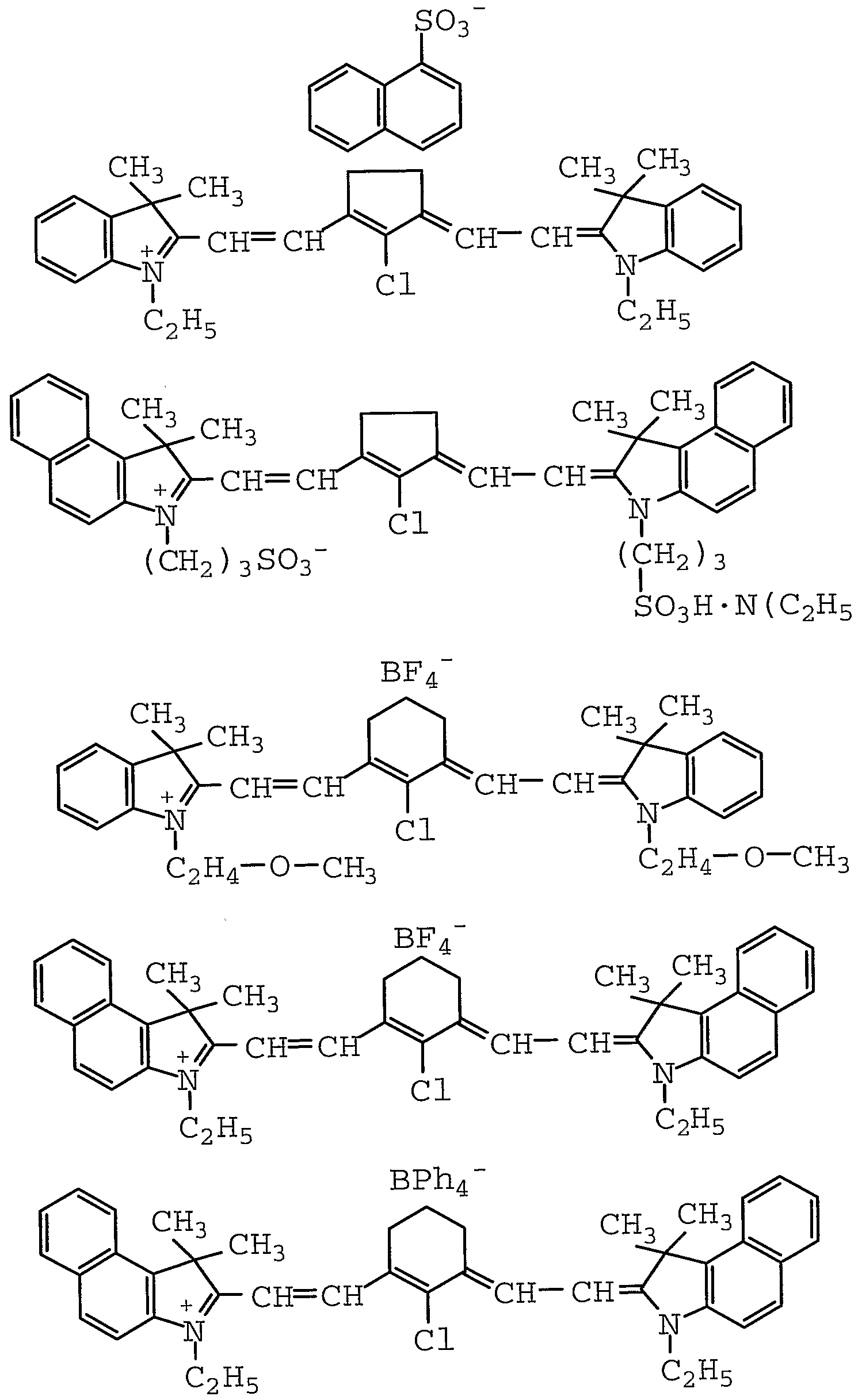
また、 上記ポジ型感光性組成物を構成する (P— 2 ) 成分の光熱変換物質とし ては、 画像露光光源の光を吸収して熱に変換し得る化合物であれば特に限定され ないが、 波長 6 0 0〜 1 3 0 0 n mの近赤外領域に吸収極大を有する有機または 無機の染顔料、 有機色素、 金属、 金属酸化物、 金属炭化物、 金属硼化物等が挙げ られる中で、 光吸収色素が特に有効である。
これらの光吸収色素としては、 窒素原子、 酸素原子または硫黄原子等の複素原 子がポリメチン (一 C H =) n鎖で結合された構造のものであり、 代表的には、 そ の複素原子が複素環を形成し、 ポリメチン鎖を介して複素環が結合された構造の 所謂、 広義のシァニン系色素、 具体的には、 例えば、 キノリン系 (所謂、 狭義の シァニン系) 、 インドール系 (所謂、 インドシァニン系) 、 ベンゾチアゾール系
(所謂、 チオシァニン系) 、 ピリリウム系、 チォピリリウム系、 スクァリ リウム 系、 クロコニゥム系、 ァズレニウム系等、 および、 ポリメチン鎖を介して非環式 複素原子が結合された構造の所謂、 ポリメチン系色素等が挙げられ、 中でも、 キ ノリン系、 インドール系、 ベンゾチアゾール系、 ピリリウム系、 チォピリリウム 系等のシァニン系色素またはポリメチン系色素が好ましい。 また、 その他の光吸 収色素として、 ジィミニゥム系色素、 フタロシアニン系色素等が挙げられ、 中で もジイミニゥム系色素が好ましい。
本発明においては、 上記シァニン系色素の中で、 キノリン系色素としては、 特 に、 下記の一般式 ( l ) , ( I b ) 又は (I c ) で表されるものが好ましい。
Xa
R1 式 (I a ) 、 (I b ) 及び (I c ) 中、 R 1及び R 2は各々独立して、 置換基を 有していてもよいアルキル基、 置換基を有していてもよいアルケニル基、 置換基 を有していてもよいアルキニル基、 または、 置換基を有していてもよいフエニル 基を示し、 L 1は置換基を有していてもよいトリ、 ペンタ、 ヘプタ、 ノナ又はゥン デカメチン基を示し、 当該ペンタ、 ヘプタ、 ノナ又はゥンデカメチン基上の 2つ の置換基が互いに連結して炭素数 5〜 7のシクロアルケン環を形成していてもよ く、 キノリン環は置換基を有していてもよく、 その場合、 P舞接する 2つの置換基 が互いに連結して縮合ベンゼン環を形成していてもよい。 X a—は対ァニオンを示 す。
ここで、 式 (I a ) 、 (l b ) 及ぴ (I c ) 中の R 1及び R 2がアルキル基であ るときの炭素数は通常 1〜 1 5、 好ましくは 1〜 1 0、 アルケニル基、 アルキニ ル基であるときの炭素数は通常 2〜 1 5、 好ましくは 2〜1 0であり、 フヱニル
基も含めたそれらの置換基としては、 炭素数が通常 1〜 1 5、 好ましくは 1〜 1 0のアルコキシ基、 フエノキシ基、 ヒドロキシ基またはフヱニル基等力 s挙げられ、 L 1における置換基としては、 同上炭素数のアルキル基、 アミノ基またはハロゲン 原子等が挙げられ、 キノリン環における置換基としては、 同上炭素数のアルキル 基、 同上炭素数のアルコキシ基、 ニトロ基またはハロゲン原子等が挙げられる。 また、 インドール系およびべンゾチァゾール系色素としては、 特に、 下記の一 般式 (I I ) で表されるものが好ましい。
式 (I I ) 中、 Y
1及び Y
2は各々独立して、 ジアルキルメチレン基または硫黄 原子を示し、 R
3及び R
4は各々独立して、 置換基を有していてもよいアルキル基、 置換基を有していてもよいアルケニル基、 置換基を有していてもよいアルキニル 基または置換基を有していてもよいフエ二ル基を示し、 L
2は置換基を有していて もよレ トリ、 ペンタ、 ヘプタ、 ノナ又はゥンデカメチン基を示し、 当該ペンタ、 ヘプタ、 ノナ又はゥンデカメチン基上の 2つの置換基が互いに連結して炭素数 5 〜 7のシクロアルケン環を形成していてもよく、 縮合ベンゼン環は置換基を有し ていてもよく、 その場合、 隣接する 2つの置換基が互いに連結して縮合ベンゼン 環を形成していてもよい。 X a一は対ァニオンを示す。
ここで、 式 (I I ) 中の R 3及び R 4がアルキル基であるときの炭素数は通常 1 〜 1 5、 好ましくは 1〜 1 0、 アルケニル基、 アルキニル基であるときの炭素数 は通常 2〜 1 5、 好ましくは 2〜 1 0であり、 フエ二ル基も含めたそれらの置換 基としては、 炭素数が通常 1〜 1 5、 好ましくは 1〜 1 0のアルコキシ基、 フエ
ノキシ基、 ヒドロキシ基またはフエ二ル基等力5'挙げられ、 L2における置換基とし ては、 同上炭素数のアルキル基、 アミノ基またはハロゲン原子等が挙げられ、 縮 合べンゼン環における置換基としては、 同上炭素数のアルキル基、 同上炭素数の アルコキシ基、 二ト口基またはハロゲン原子等が挙げられる。
また、 ピリリウム系およびチォピリリウム系色素としては、 特に、 下言 Bの一般 式 (I I I a) 、 (I I I b) 又は (I I I c) で表されるものが好ましい。
式 (I I I a) 、 (I I I b) 及び (I I I c) 中、 Z
1及び Z
2は各々独立し て、 酸素原子または硫黄原子を示し、 R
5、 R
6、 R
7及び R
8は各々独立して、 水 素原子またはアルキル基、 または、 R
5と R
7及び R
6と R
8が互いに連結して炭素 数 5又は 6のシクロアルケン環を形成していてもよく、 L
3は置換基を有していて
もよいモノ、 トリ、 ペンタ又はヘプタメチン基を示し、 当該トリ、 ペンタ又はへ プタメチン基上の 2つの置換基が互いに連結して炭素数 5〜 7のシクロアルケン 環を形成していてもよく、 ピリリウム環およびチアピリリウム環は置換基を有し ていてもよく、 その場合、 隣接する 2つの置換基が互いに連結して縮合ベンゼン 環を形成していてもよい。 X a—は対ァニオンを示す。
ここで、 式 (ェ I I a) 、 (ェ I I b) 及び (I I I c) 中の R5、 R6、 R7及 ぴ R 8がアルキル基であるときの炭素数は通常 1〜 15、 好ましくは 1〜 10であ り、 L3における置換基としては、 同上炭素数のアルキル基、 アミノ基またはハロ ゲン原子等が挙げられ、 ピリリウム環およびチアピリリゥム環における置換基と しては、 フエニル基、 ナフチル基等のァリール基等力 s挙げられる。
また、 ポリメチン系色素としては、 特に、 下記の一般式 (IV) で表されるも のが好ましい。
式 (IV) 中、 R
9、 R
1Q、 R
11及び R
12は各々独立して、 アルキル基を示し、 R
13及び R
14は各々独立して、 置換基を有していてもよいァリール基、 フリル基 またはチェ二ル基を示し、 L
4は置換基を有していてもよいモノ、 トリ、 ペンタ又 はヘプタメチン基を示し、 当該トリ、 ペンタ又はヘプタメチン基上の 2つの置換 基が互いに連結して炭素数 5〜7のシクロアルケン環を形成していてもよく、 キ ノン環およびベンゼン環は置換基を有していてもよい。 X a—は対ァニオンを示す。 ここで、 式 (IV) 中の R
9、 R
1Q、 R
11及ぴ R
12のアルキル基の炭素数は通 常 1〜 15、 好ましくは 1〜 10、 R
13及び R
14がァリール基であるときの炭素 数は通常 6〜20、 好ましくは 6〜15であり、 R
13及び R
14として具体的には、
T/JP02/04144
24 フエニル基、 1一ナフチル基、 2—ナフチル基、 2—フリル基、 3—フリル基、 2—チェニル基、 3—チェニル基等が挙げられ、 それらの置換基としては、 同上 炭素数のアルキル基、 同上炭素数のアルコキシ基、 ジアルキルアミノ基、 ヒドロ キシ基またはハロゲン原子等が挙げられ、 L 4における置換基としては、 同上炭素 数のアルキル基、 アミノ基またはハロゲン原子等が挙げられ、 キノン環およびべ ンゼン環における置換基としては、 同上炭素数のアルキル基、 同上炭素数のアル コキシ基、 ニトロ基またはハロゲン原子等が挙げられる。
更に、 ジィミニゥム系色素としては、 特に、 N, N—ジァリールイミ二ゥム塩 骨格を少なくとも 1個有する下記の一般式 (V a ) 又は (V b ) で表されるもの が女子ましい。
式 (Va) 及び (Vb) 中、 R
15、 R
16、 R
17及び R
18は各々独立して、 水素 原子、 ハロゲン原子、 置換基を有していてもよいアルキル基、 置換基を有してい てもよいアルケニル基、 置換基を有していてもよいアルキニル基または置換基を 有していてもよいアルコキシ基を示し、 R
19及び R
2Qは各々独立して、 置換基を 有していてもよいアルキル基、 置換基を有していてもよいアルケニル基、 置換基 を有していてもよいアルキニル基、 置換基を有していてもよいアルコキシ基、 置 換基を有していてもよいァシルォキシ基または置換基を有していてもよいフエ二 ル基を示し、 ベンゼン環おょぴィミノキノン環は置換基を有していてもよい。 X a—は対ァニオンを示す。 なお、 式 (Vb) 中の電子結合 (点線) は他の電子結 合との共鳴状態を示す。
ここで、 式 (Va) 及ぴ (Vb) 中の R15、 R16、 R17、 R18、 R19及び R2 0がアルキル基、 アルコキシ基であるときの炭素数は通常 1〜 15、 好ましくは 1 〜10、 アルケニル基、 アルキニル基であるときの炭素数は通常 2〜 15、 好ま しくは 2〜 10であり、 それらにおける置換基としては、 同上炭素数のアルキル 基、 同上炭素数のアルコキシ基、 カルボキシ基、 ァシルォキシ基、 アルコキシ力 ルポ二ル基、 ヒドロキシ基、 アミノ基、 アルキルアミノ基、 ハロゲン化アルキル 基またはハロゲン原子等が挙げられ、 ベンゼン環おょぴィミノキノン環における 置換基としては、 同上炭素数のアルキル基、 同上炭素数のアルコキシ基、 ァシル 基、 ニトロ基またはハロゲン原子等が挙げられる。
これらのジィミニゥム系色素の中では、 上記の一般式 (Va) 及ぴ (Vb) 中 の R15、 R16、 R 17及ぴ R 18がアルキル基で、 R 19及ぴ R 2 Qもアルキル基であ るか、 R 19及び R 2 Qがジアルキルアミノ基を置換基として有するフエニル基であ るもの力 s、 特に好ましい。
なお、 上記の一般式 (I a〜 (:) 、 (I I) , (I I I a〜c) 、 (I V) 及 び (Va〜b) における対ァニオン X a—としては、 例えば、 C 1一、 B r_、 I一、 C 104一、 PF6一、 S b F6一、 A s F6—、 および、 BF4—、 BC 14一等の無機
04144
26 硼酸等の無機酸ァニオン、 ならびに、 ベンゼンスルホン酸、 トルエンスルホン酸、 ナフタレンスルホン酸、 酉乍酸、 および、 メチル、 ェチル、 プロピル、 ブチル、 フヱ ニル、 メ トキシフエ二ル、 ナフチル、 フルオロフェニル、 ジフルオロフェニル、 ペンタフルオロフヱニル、 チェニル、 ピロリル等の有機基を有する有機硼酸等の 有機酸ァニォンを挙げることが出来る。
また、 上記の一般式 (I a〜c) 、 (11) 、 (I I I a〜c) 及び (I V) においては、 L L2、 L 3及び L 4のポリメチン鎖上に、 下記の一般式 (VI) で表されるバルビツル酸ァニオン基またはチォバルビツル酸ァニォン基を置換基 として有することにより、 または、 L L 3及び L 4のポリメチン鎖中に、 下記の一般式 (VI I) で表されるスクェア酸ァニオン基またはチォスクェア酸 ァニオン基、 あるいは、 下記の一般式 (VI I I) で表されるクロコン酸ァニォ ン基またはチォクロコン酸ァニオン基を形成することにより、 分子内塩を形成し ていてもよい。
(VI)
(VIェェ)
式 (V I) 、 (V I I) 及び (V I I I) 中、 z
3、 z z
5、 z
6、 z
7及び Z
8は各々独立して、 酸素原子または硫黄原子を示し、 R
35及び R
36は各々独立 して、 水素原子、 置換基を有していてもよいアルキル基、 置換基を有していても よいアルケニル基、 置換基を有していてもよいアルコキシ基または置換基を有し ていてもよいフエ二ル基を示す。
ここで、 式 (V I) 中の R35及び R36がアルキル基、 アルコキシ基であるとき の炭素数は通常 1〜15、 好ましくは 1〜5、 アルケニル基であるときの炭素数 は通常 2〜15、 好ましくは 2〜 5であるが、 アルキル基であるのが好ましく、 そのアルキル ¾として具体的には、 メチル基、 ェチル基、 プロピル基またはブチ ル基等が挙げられる。
また、 フタロシアニン系色素は、 ァザポリメチン鎖を介して複素環が結合され た構造を基本構造とするものであり、 そのフタロシアニン系色素としては、 下記 の一般式 (IX) で表されるものカ好ましい。
式 (IX) 中、 R
21及ぴ R
22は各々独立して、 アルコキシ基、 チォアルコキシ 基、 ァリールォキシ基、 チオアリールォキシ基、 アルキルアミノ基、 ァリールァ ミノ基、 ハロゲン原子または水素原子を示し、 Mは、 Zn、 Cu、 N i、 SnC 1
2、 A 1 C 1又は水素原子を示し、 また、 ベンゼン環における隣接する 2つの置 換基カ s互いに連結して縮合環を形成していてもよい。
ここで、 式 (IX) 中の R 21及び R 22がアルコキシ基、 チォアルコキシ基また はアルキルアミノ基であるときの炭素数は通常 1〜 10、 好ましくは 1〜4であ り、 ァリールォキシ基、 チオアリールォキシ基またはァリールアミノ基としては、 フエノキシ基、 チオフエノキシ基またはフヱニルァミノ基等が挙げられ、 また、 Mとしては、 Z n又は S n C 12であるのが好ましい。
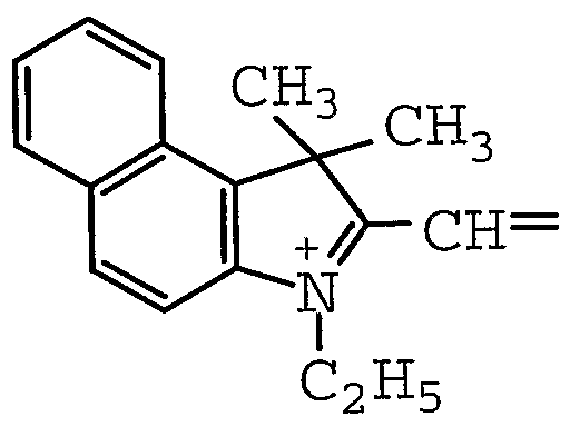
上記の一般式 (I a〜c) で表されるキノリン系、 上記の一般式 (I I) で表
されるインドール系またはべンゾチアゾール系、 上記の一般式 (I I I a〜c) で表されるピリリウム系またはチォピリリウム系等のシァニン系色素、 上記の一 般式 (IV) で表されるポリメチン系色素、 上記の一般式 (Va〜b) で表され るジイミ二ゥム系色素および上記の一般式 (IX) で表されるフタロシアニン系 色素の中で、 本発明においては、 上記の一般式 (I a〜c) で表されるキノリン 系、 上記の一般式 (I I) で表されるインドール系またはべンゾチァゾール系、 上記の一般式 ( I I I a〜 c ) で表されるピリリウム系またはチォピリリウム系 等のシァニン系色素、 上記の一般式 (IV) で表されるポリメチン系色素または 上記の一般式 (Va〜b) で表されるジィミニゥム系色素が好ましく、 上記の一 般式 (I I) で表されるィンドール系またはべンゾチアゾ一ル系のシァニン色素 が特に好ましい。
なお、 上記の一般式 (I a〜c) で表されるキノリン系、 上記の一般式 (I I) で表されるインドール系またはべンゾチアゾール系、 上記の一般式 (I I I a〜 c) で表されるピリリウム系またはチォピリリウム系等のシァニン系色素、 上記 の一般式 (IV) で表されるポリメチン系色素および上記の一般式 (Va〜b) で表されるジィミニゥム系色素の各具体例を以下に示す。
H H
)
'
()H 2—
(11-
(
(ェエ- 7)
(ェエー 8)
(Iエー 9)
(ェエ- 12)
(ェエー 14)
(ェエ- 15)
C¾ CH3 0
CH3S
III
(ェェエー 6)
Cつ Hc
(IIエー 7)
CH30' OCHつ
(ェェエー 8)
(ェェエー 9)
(ェェエー 10)
(
9)ΛΙ
本発明において、 上記ポジ型感光性組成物における上記 (P— 1 ) 成分のアル 力リ可溶性樹脂の含有割合は、 5 0〜 9 9重量0 /0であるのが好ましく、 6 0〜 9 8重量%であるのが更に好ましく、 7 0〜9 7重量%であるのが特に好ましい。 また、 上記 ( P - 2 ) 成分の光熱変換物質の含有割合は、 0 . 5〜3 0重量%で あるのが好ましく、 1〜2 0重量%であるのが更に好 しく、 2〜1 0重量%で あるのが特に好ましい。
また、 上記ポジ型感光性組成物には、 露光部と非露光部のアルカリ現像液に対 する溶解性の差を増大させる目的で、 赤外領域の光で分解されない溶解抑止剤
( P - 3 ) 成分が含有されていてもよく、 その溶解抑止剤としては、 例えば、 特 開平 1 0— 2 6 8 5 1 2及ぴ特開平 1 1一 2 8 8 0 8 9の各公報に詳細に記載さ れているスルホン酸エステル類、 燐酸エステル類、 芳香族カルボン酸エステル類、 芳香族ジスルホン類、 力ルポン酸無水物類、 芳香族ケトン類、 芳香族アルデヒド 類、 芳香族ァミン類、 芳香族エーテル類、 トリアリールメタン骨格を有する化合 物類等、 特開平 1 1— 1 9 0 9 0 3に詳細に記載されている、 ラクトン骨格、 N, N—ジァリールアミド骨格、 ジァリ一ルメチルイミノ骨格を有する酸発色性色素 類、 特開平 1 1— 1 4 3 0 7 6に詳細に記載されている、 ラクトン骨格、 チォラ クトン骨格、 スルホラクトン骨格を有する塩基発色性色素類等を挙げることが出
¾る。
更に、 溶解抑止剤として、 例えば、 ポリェチレングリコール類、 ポリエチレン グリコールポリプロピレングリコールブロックコポリマー類、 ポリエチレングリ コールアルキルエーテル類、 ポリエチレングリコールポリプロピレングリコール アルキルエーテル類、 ポリエチレングリコールアルキルフエニルエーテル類、 ポ リエチレングリコール脂肪酸エステル類、 ポリェチレングリコールアルキルアミ ン類、 ポリエチレングリコールアルキルアミノエ一テル類、 グリセリン脂肪酸ェ ステル及びそのポリエチレンォキサイ ド付加物類、 ソルビタン脂肪酸エステル及 びそのポリエチレンォキサイ ド付加物類、 ソルビッ ト脂肪酸エステル及びそのポ
リエチレンォキサイ ド付加物類、 ペンタエリスリッ ト脂肪酸エステル及びそのポ リエチレンォキサイ ド付加物類、 ポリグリセリン脂肪酸エステル類等のノニオン 性界面活性剤力 s'挙げられる。
本発明において、 上記ポジ型感光性組成物における上記 (P_3) 成分の溶解 抑止剤の含有割合は、 50重量%以下であるのが好ましく、 0. 01〜30重量 %であるの力 s更に好ましく、 0. 1〜20重量0 /0であるのが特に好ましい。
また、 上記ポジ型感光性組成物には、 アンダー現像性の付与等の現像性の改良 を目的として、 好ましくは p K aが 2以上の有機酸またはその有機酸の無水物 (P-4) 成分が含有されていてもよく、 その有機酸またはその無水物としては、 例えば、 特開昭 60— 88942、 特開昭 63— 276048、 特開平 2— 9 6 754の各公報等に記載されたものが使用され、 具体的には、 グリセリン酸、 メ チルマロン酸、 ジメチルマロン酸、 プロピルマロン酸、 コハク酸、 リンゴ酸、 メ ソ酒石酸、 グルタル酸、 /?—メチルグルタル酸、 β , ージメチルグルタル酸、 一ェチルグルタル酸、 β , ?一ジェチルグルタル酸、 /3—プロピルグルタル酸、 β , ^—メチルプロピルグルタル酸、 ピメリン酸、 スベリン酸、 セバシン酸等の 脂肪族飽和カルボン酸、 マレイン酸、 フマル酸、 グルタコン酸等の脂肪族不飽和 カルボン酸、 1, 1ーシクロブタンジカルボン酸、 1, 3—シクロブタンジカル ボン酸、 1, 1—シクロペンタンジカルボン酸、 1, 2—シクロペンタンジカル ボン酸、 1, 1—シクロへキサンジカルボン酸、 1, 2—シクロへキサンジカル ボン酸、 1, 3—シクロへキサンジカルボン酸、 1, 4—シクロへキサンジカル ボン酸等の炭素環式飽和カルボン酸、 1, 2—シクロへキセンジカルボン酸、 2, 3—ジヒドロキシ安息香酸、 3, 4一ジメチル安息香酸、 3, 4ージメ トキシ安 息香酸、 3, 5—ジメ トキシ安息香酸、 ρ—トルィル酸、 2—ヒ ドロキシ一 ρ 一トルィル酸、 2—ヒドロキシー in—トルィル酸、 2—ヒドロキシ _ 0—トルイ ル酸、 マンデル酸、 没食子酸、 フタル酸、 イソフタル酸、 テレフタル酸等の炭素 環式不飽和カルボン酸、 および、 メルドラム酸、 ァスコルビン酸、 無水コハク酸、
無水グルタル酸、 無水マレイン酸、 シクロへキセンジカルボン酸無水物、 シクロ へキサンジカルボン酸無水物、 無水フタル酸等の無水物力 s、挙げられる。
本発明において、 上記ポジ型感光性組成物における上記 (P— 4) 成分の有機 酸またはその無水物の含有割合は、 30重量%以下であるのが好ましく、 20重 量%以下であるのが更に好ましく、 10重量%以下であるのが特に好ましい。
また、 上記ポジ型感光性組成物には、 例えば、 ビクトリアピュアブルー (42 595) 、 クリスタルバイォレッ ト (42555) 、 クリスタルバイォレツ トラ ク トン、 オーラミン 0 (41000) 、 カチロンブリリアントフラビン (ベーシッ ク 13) 、 ローダミン 6 GCP (45160) 、 ローダミン B (451 70) 、 サフラニン〇K70 : 100 (50240) 、 エリォグラウシン X (42080) 、 ファーストブラック ΗΒ (2615 0 ) 、 N o . 1 2 0Zリ オノールイェロー (2 1090) 、 リオノールイェロー GRO (2 1090) 、 シムラーファース トイエロー 8 GF (21 105) 、 ベンジジンイェロー 4 Τ一 564 D (2 1 0 95) 、 シムラーファーストレッ ド 401 5 (12355) 、 リオノールレッ ド Β 4401 (1 5850) 、 ファーストゲンブルー TGR— L (74 1 6 0 ) 、 リオノールブルー SM (26 1 50) 等の顔料または染料等の着色剤 (Ρ— 5) 成分が含有されていてもよい。 なお、 ここで、 上記の括弧内の数字はカラーイン デックス (C. I. ) を意味する。
本発明において、 上記ポジ型感光性組成物における上記 (Ρ— 5) 成分の着色 剤の含有割合は、 50重量%以下であるのが好ましく、 0. 5〜 30重量%であ るのが更に好ましく、 2〜20重量%であるのが特に好ましい。
また、 上記ポジ型感光性組成物には、 アルカリ可溶性樹脂が上記フヱノール性 水酸基含有フヱノール樹脂であるとき、 露光およぴ現像後の後加熱により当該樹 脂を架橋させてポジ画像に耐薬品性、 耐刷性等を付与することを目的として、 そ のフヱノール樹脂を架橋させる作用を有する架橋剤 (Ρ-6) 成分が含有されて いてもよく、 その架橋剤としては、 代表的には、 官能基としてメチロール基、 そ
れをアルコール縮合変性したアルコキシメチル基、 その他、 ァセトキシメチル基 等を少なくとも 2個有するァミノ化合物が挙げられ、 具体的には、 メラミン誘導 体、 例えば、 メ トキシメチル化メラミン (三井サイテック社製、 サイメル 3 0 0 シリーズ ( 1 ) 等) 、 ベンゾグアナミン誘導体 (メチル Zェチル混合アルコキシ ィ匕べンゾグアナミン樹脂 (三井サイテック社製、 サイメル 1 1 0 0シリーズ (2 ) 等) ) 、 グリコールゥリル誘導体 (テトラメチロールグリコールゥリル樹脂 (三 井サイテック社製、 サイメル 1 1 0 0シリーズ (3 ) 等) ) や、 尿素樹脂誘導体、 レゾール樹脂等が挙げられる。
本発明において、 ポジ型感光性組成物における上記 (P—6 ) 成分の架橋剤の 含有割合は、 2 0重量%以下であるのが好ましく、 1 0重量%以下であるのが更 に好ましく、 5重量%以下であるの力 寺に好ましい。
また、 上記ポジ型感光性組成物には、 感度の向上や現像性の改良等を目的とし て、 ノニオン性、 ァニオン性、 或いは雨性等の界面活性剤 (P— 7 ) 成分が含有 されていてもよく、 更に、 例えば、 塗布性改良剤、 密着性改良剤、 感度改良剤、 感脂化剤、 現像性改良剤等の感光性組成物に通常使用される各種の添加剤が更に 2 0重量%以下、 好ましくは 1 0重量%以下の範囲で含有されていてもよい。 上記ノニォン性界面活性剤としては、 例えば、 ポリエチレングリコール、 ポリ エチレングリコールポリプロピレングリコ一ルブロックコポリマー等のポリェチ レングリコール類、 ポリエチレングリコールセチルエーテル、 ポリエチレングリ コールステアリルエーテル、 ポリエチレングリコールォレイルエーテル、 ポリエ チレングリコールべへニルエーテル等のポリエチレングリコールアルキルエーテ ル類、 ポリエチレングリコールポリプロピレングリコールセチルエーテル、 ポリ エチレングリコールポリプロピレングリコールデシルテトラデシルエーテル等の ポリェチレングリコールポリプロピレングリコールアルキルェ一テル類、 ポリェ チレングリコールォクチルフエニルエーテル、 ポリエチレングリコールノニルフエ ニルエーテル等のポリエチレングリコールアルキルフエニルエーテル類、 モノス
テアリン酸エチレングリコール、 ジステアリン酸エチレングリコール、 ステアリ ン酸ジエチレングリコール、 ジステアリン酸ポリエチレングリコール、 モノラウ リン酸ポリエチレングリコール、 モノステアリン酸ポリエチレングリコール、 モ ノォレイン酸ポリエチレングリコール等のポリエチレングリコール脂肪酸エステ ル類、 モノミリスチン酸グリセリル、 モノステアリン酸グリセリル、 モノイソス テアリン酸グリセリル、 ジステアリン酸グリセリル、 モノォレイン酸グリセリル、 ジォレイン酸グリセリル等のグリセリン脂肪酸エステル類およびそのポリェチレ ンォキサイ ド付加物類、 ポリグリセリン脂肪酸エステル類、 モノステアリン酸べ ンタエリスリット、 トリステアリン酸ペンタエリスリット、 モノォレイン酸ペン タエリスリット、 トリオレイン酸ペンタエリスリッ ト等のペンタエリスリ ッ ト脂 肪酸エステル類おょぴそのポリエチレンォキサイド付加物類、 モノパルミチン酸 ソルビタン、 モノステアリン酸ソルビタン、 トリステアリン酸ソルビタン、 モノ ォレイン酸ソルビタン、 トリオレイン酸ソルビタン等のソルビタン脂肪酸エステ ル類およびそのポリエチレンオキサイ ド付加物類、 モノラウリン酸ソルビッ ト、 テトラステアリン酸ソルビット、 へキサステアリン酸ソルビッ ト、 テトラオレィ ン酸ソルビット等のソルビット脂肪酸エステル類おょぴそのポリエチレンォキサ ィド付加物類、 ポリエチレングリコールアルキルアミン類、 ポリエチレングリコー ルアルキルアミノエ一テル類、 ヒマシ油のポリエチレンオキサイド付加物類、 ラ ノリンのポリエチレンォキサイド付加物類等を挙げることが出来る。
また、 ァニオン性界面活性剤としては、 例えば、 ラウリン酸ナトリウム、 ステ アリン酸ナトリウム、 ォレイン酸ナトリウム等の高級脂肪酸塩類、 ラウリルスル ホン酸ナトリウム等のアルキルスルホン酸塩類、 ドデシルベンゼンスルホン酸ナ トリウム等のアルキルベンゼンスルホン酸塩類、 ィソプロピルナフタレンスルホ ン酸ナトリゥム等のアルキルナフタレンスルホン酸塩類、 アルキルジフエニルエー テルジスルホン酸ナトリゥム等のアルキルジフエニルエーテルジスルホン酸塩類、 ポリォキシエチレンラウリルエーテルスルホン酸ナトリゥム等のポリ才キシェチ
レンアルキルエーテルスルホン酸塩類、 ラウリル硫酸ナトリウム、 ステアリル硫 酸ナトリゥム等のアルキル硫酸エステル塩類、 ォクチルアルコール硫酸エステル ナトリウム、 ラウリルアルコール硫酸エステルナトリウム、 ラウリルアルコール 硫酸エステルアンモニゥム等の高級アルコール硫酸エステル塩類、 ァセチルアル コール硫酸エステルナトリウム等の脂肪族アルコール硫酸ェステル塩類、 ポリォ キシエチレンラウリルエーテル硫酸ナトリゥム、 ポリオキシエチレンラウリルエー テル硫酸アンモニゥム、 ポリォキシエチレンラウリルエーテル硫酸トリエタノー ルァミン等のポリオキシエチレンアルキルエーテル硫酸塩類、 ポリオキシェチレ ンノニルフエニルエーテル硫酸ナトリウム等のポリォキシエチレンアルキルフエ ニルエーテル硫酸塩類、 ラウリル燐酸ナトリウム、 ステアリル燐酸ナトリウム等 のアルキル燐酸エステル塩類、 ポリオキシエチレンラウリルエーテル燐酸ナトリ ゥム、 ポリォキシエチレンステアリルエーテル燐酸ナトリウム等のポリォキシェ チレンアルキルエーテル燐酸塩類、 ポリォキシエチレンノニルフエニルエーテル 燐酸ナトリウム等のポリォキシエチレンアルキルフエニルエーテル燐酸塩類、 ス ルホコハク酸類、 不飽和脂肪酸硫酸化油類、 タウリン塩類、 ヒマシ油硫酸エステ ル塩類等を挙げることが出来る。
また、 両性界面活性剤としては、 例えば、 ; —ラウリル一 ; N, N—ジメチル —N—カルボキシメチルアンモニゥム、 N—ステアリル一 N, N—ジメチル _ N —カルポキシメチルアンモニゥム、 N—ラウリル一 N, N—ジヒドロキシェチル 一 N _カルボキシメチルアンモニゥム、 N—ラウリル一 N, N, N—トリス (力 ルポキシメチル) アンモニゥム等のベタイン型化合物類、 2—アルキル一 N—力 ルボキシメチルー N—ヒドロキシェチルイミダゾリゥム等のィミダゾリゥム塩類、 ィミダゾリンー N—ナトリウムェチルスルホネート、 イミダゾリンー N—ナトリ ゥムェチルスルフェート等のイミダゾリン類、 ァミノカルボン酸類、 ァミノ硫酸 エステル類等を挙げることが出来る。
本発明において、 ポジ型感光性組成物における上記界面活性剤の含有割合は、
0. 001〜 5重量0 /0であるのが好ましく、 0. 002〜3重量%であるのが更 に好ましく、 0. 005〜 1重量0 /0であるの力 s特に好ましい。
また、 ポジ型感光性組成物には、 上記の成分以^^こ、 例えば、 塗布性改良剤、 密着性改良剤、 感度改良剤、 感脂化剤、 現像性改良剤等の感光性組成物に通常使 用される各種の添加剤が更に 20重量%以下、 好ましくは 10重量%以下の範囲 で含有されていてもよい。
なお、 上記ポジ型感光性組成物は、 ォニゥム塩、 ジァゾニゥム塩、 キノンジァ ジド基含有化合物等の、 紫外線領域の光に感受性を有する化合物を含まず、 紫外 線領域の光に対して実質的に感受性を有さないものである。 ここで、 紫外線領域 の光に対して実質的に感受性を有さないとは、 360〜450 nmの波長の光に よる照射の前後で、 アルカリ現像液に対する溶解性に実質的有意差を生じず、 実 用的な意味での画像形成能を有さないことを意味する。
次に、 感光性層を構成するネガ型感光性組成物について説明する。 本発明にお ける感光性組成物の中で、 ネガ型感光性組成物としては、 下記の (N— 1) 成分、
(N— 2) 成分、 (N—3) 成分及び (N—4) 成分を含有する光重合性の組成 物が好ましい。
(N-1) 高分子結合剤
(N-2) ェチレン性不飽和化合物
(N-3) 増感剤
(N-4) 光重合開始剤
本発明における光重合性組成物を構成する (N_l) 成分の高分子結合材は、 (N-2) 成分のエチレン性不飽和化合物、 (N-3) 成分の増感剤および (N 一 4) 成分の光重合開始剤等のバインダーとしての機能を有するものであり、 そ の高分子結合材としては、 例えば、 (メタ) アクリル酸、 (メタ) アクリル酸ェ ステル、 (メタ) アクリロニトリル、 (メタ) アクリルアミ ド、 マレイン酸、 ス チレン、 酢酸ビニル、 塩ィ匕ビニリデン、 マレイミ ド等の単独または共重合体、 並
びに、 ポリアミ ド、 ポリエステル、 ポリエーテル、 ポリウレタン、 ポリビニルブ チラール、 ポリビニルピロリ ドン、 ポリエチレンオキサイ ド、 ァセチルセルロー ス等が挙げられるが、 中でも、 アルカリ現像性の面から、 カルボキシル基含有重 合体が好適であり、 具体的には、 (メタ) アクリル酸と (メタ) アクリル酸アル キル (炭素数 1〜10) エステル、 または、 更にスチレンを共重合成分として含 有する共重合体が好ましく、 このカルボキシル基含有重合体の酸価は 10〜 25 0、 重量平均分子量は 0. 5〜 100万であるのが好ましい。
更に、 高分子結合材として、 側鎖にエチレン性不飽和結合を有するものカ
?好適 であり、 そのエチレン性不飽和結合として、 特に、 下記の一般式 (XI I a) 、 (X I I b) 又は (X I I c ) で表されるものが好ましい。
R 38
R 37 R36 R40 c= c一 c— z- (Xllb)
R 38 R 41
R37 R 39
C == C一 zy― (XIIc)
R 38 式 (XI I a) 、 (X I I b) 及び (XI I c) 中、 R36は水素原子またはメ チル基を示し、 R37、 R38、 R39、 R 4 Q及び R 41は各々独立して、 水素原子、 ハ ロゲン原子、 アミノ基、 ジアルキルアミノ基、 カルボキシル基、 アルコキシカル ボニル基、 スルホ基、 ニトロ基、 シァノ基、 置換基を有していてもよいアルキル
基、 置換基を有していてもよいアルコキシ基、 置換基を有していてもよいアルキ ルァミノ基、 置換基を有していてもよいアルキルスルホニル基、 置換基を有して いてもよいァリール基、 置換基を有していてもよいァリールォキシ基、 置換基を 有していてもよいァリールアミノ基、 または、 置換基を有していてもよいァリー ルスルホニル基を示し、 Z 9は酸素原子、 硫黄原子、 イミノ基、 または、 アルキル ィミノ基を示す。
ここで、 R 3 7〜R 4 1におけるアルキル基、 アルコキシ基、 アルキルアミノ基、 アルキルスルホニル基、 ァリール基、 ァリールォキシ基、 ァリールアミノ基、 ァ リールスルホニル基の置換基としては、 例えば、 アルキル基、 アルコキシ基、 ァ ルキルチオ基、 アミノ基、 ジアルキルアミノ基、 ニトロ基、 シァノ基、 フエニル 義、 および、 ハロゲン原子等が挙げられる。
上記の式 (X I I a ) で表されるエチレン性不飽和結合を側鎖に有する高分子 結合材は、 カルボキシル基含有重合体に、 ァリルグリシジルエーテル、 グリシジ ル (メタ) ァクリレート、 aーェチルグリシジル (メタ) アタリレート、 グリシ ジルクロトネート、 グリシジルイソクロトネート、 クロトニルグリシジルエーテ ル、 ィ夕コン酸モノアルキルモノグリシジルエステル、 フマル酸モノアルキルモ ノグリシジルエステル、 マレイン酸モノアルキルモノグリシジルエステル等の脂 肪族エポキシ基含有不飽和化合物、 または、 3 , 4—エポキシシクロへキシルメ チル (メタ) ァクリレート、 2, 3—エポキシシクロペンチルメチル (メタ) ァ クリレート、 7, 8 —エポキシ 〔トリシクロ 〔5 . 2 . 1 . 0〕 デシ一 2 —ィル〕
(メタ) アタリレート、 7, 8—エポキシ 〔トリシクロ 〔5 . 2 . 1 . 0〕 デシ 一 2—ィル〕 ォキシメチル (メタ) ァクリレート等の脂環式エポキシ基含有不飽 和化合物等を、 8 0〜1 2 0 °C程度の温度、 1〜5 0時間程度の時間で、 カルボ キシル基含有重合体の有する力ルポキシル基の 5〜 9 0モル%、 好ましくは 3 0 〜7 0モル0 /0程度を反応させることにより得られる。
また、 上記の式 (X I l b ) で表されるエチレン性不飽和結合を側鎖に有する
高分子結合材は、 ァリル (メタ) アタリレート、 3—ァリルォキシ一2—ヒドロ キシプロピル (メタ) ァクリレー ト、 シンナミル (メタ) アタリレート、 クロト ニル (メタ) アタリレー ト、 メタリル (メタ) ァクリレート、 N, N—ジァリル (メタ) アクリルアミ ド等の 2種以上の不飽和基を有する化合物と、 また、 上記 の式 (X I I c ) で表されるエチレン性不飽和結合を側鎖に有する高分子結合材 は、 ビニル (メタ) ァクリレー ト、 1一クロロビニル (メタ) ァクリレート、 2 —フエ二ルビニル (メタ) アタリレート、 1一プロぺニル (メタ) ァクリレート、 ビニルクロ トネー ト、 ビニル (メタ) アクリルアミ ド等の 2種以上の不飽和基を 有する化合物と、 それぞれ、 (メタ) アクリル酸等の不飽和カルボン酸または更 に不飽和カルボン酸エステルとを、 前者の不飽和基を有する化合物の全体に占め る割合を 1 0〜9 0モル0 /0、 好ましくは 3 0〜8 0モル0 /0程度となる様に共重合 させることにより得られる。
上述した高分子結合剤の中でも、 アルカリ可溶性樹脂が好ましく、 更には、 力 ルポキシル基含有ビニル系樹脂が好ましく、 特に、 側鎖にェチレン性不飽和結合 を有するものが好ましい。
本発明において、 上記ネガ型感光性組成物を構成する (N— 2 ) 成分のェチレ ン性不飽和化合物は、 組成物が活性光線の照射を受けたときに、 後述する (N - 4 ) 成分の光重合開始剤を含む光重合開始系の作用により付加重合し、 場合に より架橋、 硬ィ匕する様なラジカル重合性のエチレン性不飽和結合を分子内に少な くとも 1個有する化合物である。
ここで、 エチレン性不飽和化合物としては、 エチレン性不飽和結合を分子内に 1個有する化合物、 具体的には、 例えば、 (メタ) アクリル酸、 クロトン酸、 ィ ソクロトン酸、 マレイン酸、 ィタコン酸、 シトラコン酸等の不飽和カルボン酸お ょぴそのアルキルエステル、 (メタ) アクリロニトリル、 (メタ) アクリルアミ ド、 スチレン等、 であってもよいが、 重合性、 架橋性およびそれに伴う露光部と 非露光部の現像液溶解性の差異を拡大できる等の点から、 ェチレン性不飽和結合
を分子内に 2個以上有する化合物であるのが好ましく、 また、 その不飽和結合が (メ夕) ァクリロイルォキシ基に由来するァクリレート化合物が特に好ましい。 エチレン性不飽和結合を分子内に 2個以上有する化合物としては、 代表的には、 不飽和カルボン酸とポリヒ ドロキシ化合物とのエステル類、 (メタ) ァクリロイ ルォキシ基含有ホスフェー ト類、 ヒドロキシ (メタ) ァクリレート化合物とポリ イソシァネート化合物とのウレタン (メタ) アタリレート類、 および、 (メタ) アクリル酸またはヒ ドロキシ (メタ) アタリレー ト化合物とポリエポキシ化合物 とのエポキシ (メタ) ァクリレート類等が挙げられる。
そのエステル類としては、 具体的には、 例えば、 上記の如き不飽和カルボン酸 と、 エチレングリコール、 ジエチレングリコール、 トリエチレングリコール、 テ トラエチレングリコール、 プロピレングリコール、 トリプロピレングリコール、 トリメチレングリコール、 テトラメチレングリコール、 ネオペンチルグリコール、 へキサメチレングリコール、 ノナメチレングリコール、 トリメチロールェタン、 テトラメチロールェタン、 トリメチロールプロハ。ン、 グリセロール、 ペンタエリ スリ トール、 ジペンタエリスリ トール、 ソルビトール及ぴそれらのエチレンォキ サイ ド付加物、 プロピレンォキサイ ド付加物、 ジエタノールァミン、 トリエタノー ルァミン等の脂肪族ポリヒドロキシ化合物との反応物、 具体的には、 例えば、 ェ チレングリコールジ (メタ) ァクリレー ト、 ジエチレングリコールジ (メタ) ァ クリ レー ト、 トリエチレングリコールジ (メタ) ァクリレート、 テトラエチレン グリコールジ (メタ) アタリレート、 プロピレングリコールジ (メタ) ァクリレー ト、 トリプロピレングリコールジ (メタ) ァクリレート、 テトラメチレングリコー ルジ (メタ) ァクリレー ト、 ネオペンチルグリコールジ (メタ) アタリレート、 へキサメチレングリコ一ルジ (メタ) ァクリレー ト、 ノナメチレングリコールジ (メタ) アタリレー ト、 トリメチロールェタントリ (メタ) アタリレート、 テト ラメチロールェタントリ (メタ) ァクリレー ト、 トリメチロールプロパンジ (メ タ) ァクリレー ト、 トリメチロールプロパントリ (メタ) アタリレート、 トリメ
チロールプロパンエチレンオキサイ ド付加トリ (メタ) アタリレート、 グリセロー ルジ (メタ) アタリレート、 グリセロールトリ (メタ) アタリレート、 グリセロー ルプロピレンオキサイ ド付加トリ (メタ) アタリレート、 ペンタエリスリ トール ジ (メタ) アタリレート、 ペンタエリスリ トールトリ (メタ) ァクリレート、 ぺ ンタエリスリ トールテトラ (メタ) ァクリレート、 ジペンタエリスリ トールジ (メタ) ァクリレート、 ジペンタエリスリ トールトリ (メタ) ァクリレート、 ジ ペンタエリスリ トールテトラ (メタ) ァクリレート、 ジペンタエリスリ トールべ ンタ (メタ) ァクリレート、 ジペンタエリスリ トールへキサ (メタ) ァクリレー ト、 ソルビトールトリ (メタ) アタリレート、 ソルビトールテトラ (メタ) ァク リレート、 ソルビトールペンタ (メタ) ァクリレート、 ソルビトールへキサ (メ タ) アタリレート等おょぴ同様のクロトネート、 イソクロトネート、 マレエート、 イタコネート、 シトラコネート等が挙げられる。
更に、 そのエステル類として、 上記の如き不飽和カルボン酸と、 ヒドロキノン、 レゾルシン、 ピロガロール、 ビスフエノール F、 ビスフエノール A等の芳香族ポ リヒドロキシ化合物との反応物、 具体的には、 例えば、 ヒドロキノンジ (メタ) ァクリレート、 レゾルシンジ (メタ) アタリレート、 ピロガロールトリ (メタ) ァクリレート等、 また、 上記の如き不飽和カルボン酸と、 トリス (2—ヒドロキ シェチル) ィソシァヌレート等の複素環式ポリヒドロキシ化合物との反応物、 具 体的には、 例えば、 トリス (2—ヒドロキシェチル) イソシァヌレートのジ (メ タ) ァクリレート、 トリ (メタ) アタリレート等、 又、 不飽和カルボン酸と多価 力ルポン酸とポリヒドロキシ化合物との反応物、 具体的には、 例えば、 (メタ) アクリル酸とフタル酸とエチレングリコールとの縮合物、 (メタ) アクリル酸と マレイン酸とジエチレングリコールとの縮合物、 (メタ) アクリル酸とテレフタ ル酸とペンタエリスリ トールとの縮合物、 (メタ) アタリル酸とァジピン酸とブ タンジオールとグリセリンとの縮合物等が挙げられる。
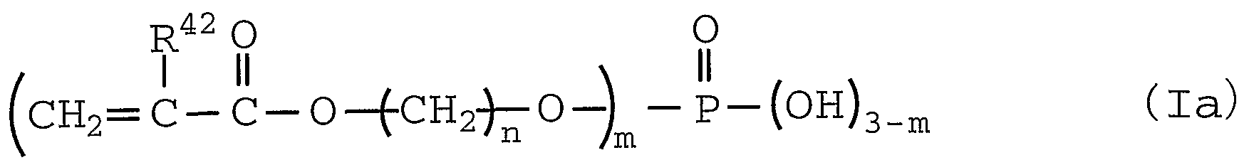
またその (メタ) ァクリロイルォキシ基含有ホスフェート類としては、 (メタ)
ァクリロイルォキシ基を含有するホスフエ一ト化合物であれば特に限定されなレ が、 中でも、 下記の一般式 ( I a ) 又は (l b ) で表されるものが好ましい。
R42 0 O
II
CH2 = C - C - 0— (cH2-CH2-0^ -P- (OH)3_m (lb)
式 (l a ) 及び (l b ) 中、 R 4 2は水素原子またはメチル基を示し、 nは 1〜 2 5の整数、 mは 1、 2又は 3である。
ここで、 nは 1〜 1 0、 特に 1〜4であるのが好ましく、 これらの具体例とし ては、 例えば、 (メタ) ァクリロイルォキシェチルホスフエ一ト、 ビス 〔 (メタ) ァクリロイルォキシェチル〕 ホスフェート、 (メタ) ァクリロイルォキシェチレ ングリコールホスフエ一ト等が挙げられ、 これらはそれぞれ単独で使用されても 混合物として使用されてもよい。
また、 そのウレタン (メタ) ァクリレート類としては、 具体的には、 例えば、 ヒドロキシメチル (メタ) ァクリレート、 ヒドロキシェチル (メタ) ァクリレー ト、 グリセロールジ (メタ) ァクリレート、 ペンタエリスリ トールトリ (メタ) ァクリレート、 テトラメチロールェタントリ (メタ) ァクリレート等のヒドロキ シ (メタ) ァクリレート化合物と、 へキサメチレンジイソシァネート、 2, 4,
シァネート、 リジンメチルエステルトリイソシァネート、 ダイマー酸ジイソシァ ネート、 1, 6, 1 1一ゥンデカトリイソシァネート、 1, 3, 6—へキサメチ レントリイソシァネート、 1, 8—ジイソシァネー ト一 4一イソシァネートメチ
ルオクタン等の脂肪族ポリイソシァネート、 シクロへキサンジイソシァネート、 ジメチルシクロへキサンジイソシァネー ト、 4, 4, ーメチレンビス (シクロへ キシルイソシァネート) 、 イソホロンジイソシァネート、 ビシクロヘプタントリ ィソシァネート等の脂環式ポリィソシァネート、 p—フエ二レンジィソシァネー ト、 2, 4— トリレンジイソシァネー ト、 2, 6— トリレンジイソシァネー ト、 キシリレンジイソシァネート、 テトラメチルキシリレンジイソシァネート、 4, 4 ' ージフエニルメタンジイソシァネー ト、 トリジンジイソシァネー ト、 1, 5 一ナフタレンジイソシァネー ト、 トリス (イソシァネー トフエニルメタン) 、 ト リス (イソシァネートフエニル) チォホスフェート等の芳香族ポリイソシァネー ト、 イソシァヌレート等の複素環式ポリイソシァネート、 等のポリイソシァネー ト化合物との反応物等が挙げられる。
中でも、 ウレタン (メタ) ァクリ ート類としては、 1分子中に 4個以上のゥ レタン結合 〔一 NH— CO—〇一〕 及び 4個以上の (メタ) ァクリロイルォキシ 基を有する化合物が好ましく、 当該化合物は、 例えば、 ペンタエリスリ トール、 ポリグリセリン等の 1分子中に 4個以上の水酸基を有する化合物に、 へキサメチ レンジイソシァネー ト、 トリメチルへキサメチレンジイソシァネー ト、 イソホロ ンジイソシァネート、 トリレンジイソシァネート等のジイソシァネート化合物を 反応させて得られた化合物 (i一 1) 、 あるいは、 エチレングリコール等の 1分 子中に 2個以上の水酸基を有する化合物に、 旭化成工業社製 「デユラネート 24 A— 100」 、 同 「デユラネート 22A_75 PX」 、 同 「デユラネート 2 1 S 一 75 E」 、 同 「デユラネート 18 H— 70 B」 等ビウレットタイプ、 同 「デュ ラネート P— 301— 75 E」 、 同 「デユラネート E— 4 0 2— 9 0 TJ 、 同 「デユラネート E— 405 _ 80 T」 等のァダクトタイプ等の 1分子中に 3個以 上のイソシァネート基を有する化合物を反応させて得られたィ匕合物 ( i _2) 、 あるいは、 イソシァネートェチル (メタ) ァクリレー ト等を重合若しくは共重合 させて得られた化合物 (i— 3) 等の、 1分子中に 4個以上、 好ましくは 6個以
上のイソシァネート基を有する化合物等、 具体的には、 例えば、 旭化成工業社製 「デユラネート ME 20— 100」 (i) と、 ペンタエリスリ トールジ (メタ) アタリレー ト、 ペンタエリスリ トールトリ (メタ) ァクリレート、 ジペンタエリ スリ トールジ (メタ) アタリレー ト、 ジペンタエリスリ トールトリ (メタ) ァク リレー ト、 ジペンタエリスリ トールテトラ (メタ) アタリレート、 ジペンタエリ スリ トールペンタ (メタ) アタリレート等の、 1分子中に 1個以上の水酸基およ び 2個以上、 好ましくは 3個以上の (メタ) ァクリロイルォキシ基を有する化合 物 (i i) とを、 反応させることにより得ることが出来る。
ここで、 上記の化合物 (i) の分子量は、 500〜200, 000であるのが 好ましく、 1, 000〜150, 000であるのが特に好ましい。 また、 上記の 様なウレタン (メタ) ァクリレー ト類の分子量は、 600〜 150, 000であ るのが好ましい。 また、 ウレタン結合を 6個以上有するの力好ましく、 8個以上 有するのが特に好ましく、 (メタ) ァクリロイルォキシ基を 6個以上有するのが 好ましく、 8個以上有するのが特に好ましい。
なお、 この様なウレタン (メタ) ァクリレート類は、 例えば、 上記化合物 ( i ) と上記化合物 (i i) とを、 トルエンや酢酸ェチル等の有機溶媒中で、 前者のィ ソシァネート基と後者の水酸基とのモル比を 1/10〜 10/1の割合として、 必要に応じてジラウリン酸 n—ブチル錫などの触媒を使用して、 10〜150°C で 5分〜 3時間程度反応させる方法により製造することが出来る。
本発明において、 上記ウレタン (メタ) ァクリレート類の中でも、 下記の一般 式 (I I) で表されるものが特に好ましい。
— Rd ェェ
X
式 (I I) 中、 R aはアルキレンォキシ基またはァリーレンォキシ基の繰り返 し構造を有し且つ Rbと結合し得るォキシ基を 4〜20個有する基を示し、 Rb 及び R cは各々独立して炭素数が 1〜 10のアルキレン基を示し、 R dは (メタ) ァクリロイルォキシ基を 1〜 10個有する有機残基を示し、 R a、 Rb、 R c及 ぴ R dは置換基を有していてもよく、 Xは 4〜20の整数、 yは 0〜1 5の整数、 zは 1〜1 5の整数である。
ここで、 式 (I I) 中の R aのアルキレンォキシ基の繰り返し構造としては、 例えば、 プロピレントリオール、 グリセリン、 ペンタエリスリ トール等に由来す るものが挙げられ、 また、 ァリーレンォキシ基の繰り返し構造としては、 例えば、 ピロガロール、 1, 3, 5—ベンゼントリオール等に由来するものが挙げられる。 また、 Rb及ぴ R cのアルキレン基の炭素数は、 各々独立して 1〜 5であるのが 好ましく、 また、 Rdにおける (メタ) ァクリロイルォキシ基は 1〜 7個である のが好ましい。 また、 Xは 4〜15、 yは 1〜: L 0、 zは 1〜10であるのが、 それぞれ好ましい。
更に、 R aとしては下記の式 (なお、 式中、 kは 2〜 10の整数である。 ) で あるのが、 また、 Rb及び R cとしては各々独立して、 ジメチレン基、 モノメチ ルジメチレン基、 または、 トリメチレン基であるのが、 また、 Rdとしては下記 の式であるのが、 それぞれ特に好ましい。
Ra チ 0 - CH2 -CH- CH2 - 0
0
Q Q
0 〇
C¾ C¾
Rd ;— O— CH2-C- CH2— 0— CH2- ■C - CH2-0-Q
C¾ C¾
〇 〇
Q Q
Q
o
C¾
0-CH2-C- CH2- 0— Q -0-CH2-CH-CH2— O— Q
C¾ CH2
O O
Q Q o
(但し、 Qは 一 C一 CH= CH2 ) また、 そのエポキシ (メタ) ァクリレート類としては、 具体的には、 例えば、 (メタ) アクリル酸または上記の如きヒドロキシ (メタ) アタリレート化合物と、 (ポリ) エチレングリコールポリグリシジルエーテル、 (ポリ) プロピレングリ コールポリグリシジルエーテル、 (ポリ) テトラメチレングリコールポリグリシ ジルエーテル、 (ポリ) ペンタメチレングリ コールポリグリシジルエーテル、
(ポリ) ネオペンチルグリコールポリグリシジルエーテル、 (ポリ) へキサメチ レングリコールポリグリシジルエーテル、 (ポリ) トリメチロールプロパンポリ
グリシジルエーテル、 (ポリ) グリセロールポリグリシジルエーテル、 (ポリ) ソルビト一ルポリグリシジルエーテル等の脂肪族ポリエポキシ化合物、 フエノー ルノボラックポリエポキシ化合物、 ブロムィ匕フエノールノボラックポリェポキシ 化合物、 (ο—, m—, p -) クレゾ一ルノボラックポリエポキシ化合物、 ビス フエノール Aポリエポキシ化合物、 ビスフエノール Fポリエポキシ化合物等の芳 香族ポリェポキシ化合物、 ソルビタンポリグリシジルエーテル、 トリグリシジル イソシァヌレート、 トリグリシジルトリス (2—ヒドロキシェチル) イソシァヌ レー ト等の複素環式ポリエポキシ化合物、 等のポリエポキシ化合物との反応物等 が挙げられる。
また、 その他のエチレン性不飽和化合物として、 上記以外に、 例えば、 ェチレ ンビス (メタ) アクリルアミ ド等の (メタ) アクリルアミ ド類、 フタル酸ジァリ ル等のァリルエステル類、 ジビニルフタレート等のビニル基含有化合物類等が挙 げられる。 以上のエチレン性不飽和化合物は、 それぞれ単独で使用されても 2種 以上が併用されてもよい。
以上の (N— 2 ) 成分のエチレン性不飽和化合物として、 本発明においては、 エステル (メタ) ァクリレート類、 (メタ) ァクリロイルォキシ基含有ホスフエ一 ト類またはウレタン (メタ) ァクリレート類カ 子ましく、 (メタ) ァクリロイル ォキシ基含有ホスフェート類またはウレタン (メタ) ァクリレート類が特に好ま しい。 (N— 2 ) 成分のエチレン性不飽和化合物全体に対して、 (メタ) アタリ ロイルォキシ基含有ホスフエ一ト類としてはその占める割合が 1〜 6 0重量%で あるのが好ましく、 2〜4 0重量0 /0であるのが特に好ましく、 又、 ウレタン (メ タ) ァクリレート類としてはその占める割合が 0 . 5〜 5 0重量%であるのが好 ましく、 2〜4 0重量%であるのが特に好ましい。
また、 上記ネガ型感光性組成物を構成する (N— 3 ) 成分の増感剤は、 3 5 0 〜 1 3 0 0 n mの波長域、 特に波長 3 5 0〜4 2 0 n mの青紫外領域および波長 6 0 0〜 1 3 0 0 n mの近赤外領域の光を効率よく吸収すると共に、 その光励起
エネルギーを後述する (N— 4) 成分の光重合開始剤に伝え、 当該光重合開始剤 を分解し、 (N—2) 成分の上記エチレン性不飽和化合物の重合を誘起する活性 ラジカルを発生させる増感機能を有する光吸収色素が好ましい。
上記の光吸収色素の中で、 波長 600〜 1300 nmの近赤外領域の光吸収色 素としては、 上記ポジ型感光性組成物を構成する (P— 2) 成分の光熱変換物質 において挙げたと同様の光吸収色素が挙げられ、 それらの中でも、 本発明におい ては、 上記の一般式 (I a〜c) で表されるキノリン系、 上記の一般式 (I I) で表されるインドール系またはべンゾチアゾール系、 上記の一般式 (I I I a〜 c) で表されるピリリウム系またはチォピリリウム系等のシァニン系色素、 上記 の一般式 (IV) で表されるポリメチン系色素または上記の一般式 (I ) 表さ れるフタロシアニン系色素が好ましく、 上記の一般式 (I I) で表されるインドー ル系またはベンゾチァゾール系のシァ二ン色素が特に好ましい。
また、 波長 350〜420 nmの青紫夕領域の光吸収色素としては、 ジアルキ ルァミノベンゼン系化合物力好ましく、 その中でも、 ジアルキルァミノべンゾフエ ノン系化合物、 および、 ベンゼン環上のアミノ基に対して p—位の炭素原子に複 素環基を置換基として有するジアルキルァミノベンゼン系化合物が好ましい。 上記のジアルキルァミノべンゾフエノン系化合物としては、 下記の一般式 (X a) で表されるものが好ましい。
(Xa)
24
R 28
R
式 (I X a) 中、 R23、 R24、 R25及び R26は各々独立して、 アルキル基を示 し、 R27、 R28、 R 29及び R 3(1は各々独立して、 アルキル基または水素原子を示 し、 R23と R24、 R25と R26、 R23と R27、 R24と R28、 R25と R29及び R2S と R 3 °とは各々独立して、 含窒素複素環を形成していてもよい。
ここで、 式 (X a) 中の R23、 R24、 R 25及ぴ R 26のアルキル基の炭素数、 並 びに、 R27、 R28、 R 29及び R 30がアルキル基であるときの炭素数は 1〜 6であ るのが好ましく、 又、 含窒素複素環を形成する場合、 5又は 6員環であるのが好 ましく、 6員環が特に好ましい。
上言己の一般式 (Xa) で表される化合物の具体例としては、 例えば、 4, 4, 一ビス (ジメチルァミノ) ベンゾフエノン、 4, 4, 一ビス (ジェチルァミノ) ベンゾフヱノン、 および、 下記構造の化合物が挙げられる。
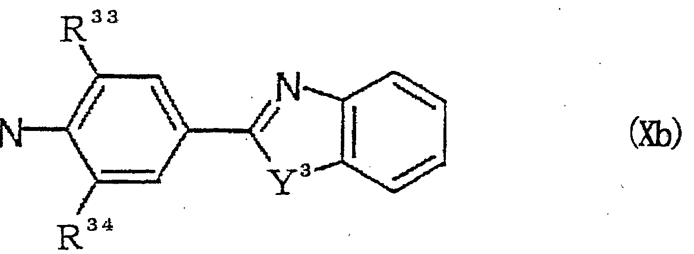
また、 ベンゼン環上のアミノ基に対して p—位の炭素原子に複素環基を置換基 として有するジアルキルァミノベンゼン系化合物における複素環基としては、 窒 素原子、 酸素原子または硫黄原子を含む 5又は 6員環のものが好ましく、 縮合べ ンゼン環を有する 5員環が特に好ましく、 そのジアルキルァミノベンゼン系化合 物としては下記の一般式 (X b ) で表されるものが特に好ましい。
式 (Xb) 中、 R
31及ぴ R
32は各々独立して、 アルキル基を示し、 R
33及び R
34は各々独立して、 アルキル基または水素原子を示し、 R
31と R
32、 R
31と R
33 及び R
32と R
34とは各々独立して、 含窒素複素環を形成していてもよい。 Y
3は、 酸素原子、 硫黄原子、 ジアルキルメチレン基、 イミノ基またはアルキルイミノ基 を示し、 当該 Y3を含む複素環に縮合するベンゼン環は置換基を有していてもよ い。
ここで、 式 (Xb) 中の R 31及び R 32のアルキル基の炭素数、 ならびに、 R33 及び R34がアルキル基であるときの炭素数は 1〜6であるのが好ましく、 又、 含 窒素複素環を形成する場合、 5又は 6員環であるのが好ましく、 6員環が特に好 ましい。 また、 Yがジアルキルメチレン基であるときのアルキル基の炭素数は 1 〜 6であるのが好ましく、 アルキルィミノ基であるときのアルキル基の炭素数は ;!〜 6であるのが好ましい。
上記の一般式 .(Xb) で表される化合物の具体例としては、 例えば、 2— (p ージメチルァミノフエニル) ベンゾォキサゾール、 2— (p—ジェチルァミノフエ ニル) ベンゾォキサゾール、 2— (p—ジメチルァミノフエニル) ベンゾ 〔4, 5〕 ベンゾォキサゾール、 2— (p—ジメチルアミノフヱニル) ベンゾ 〔6, 7〕 ベンゾォキサゾール、 2— (p—ジメチルァミノフエニル) ベンゾチアゾール、 2 - (p—ジェチルァミノフエニル) ベンゾチアゾール、 2― (p—ジメチルァ ミノフエニル) ベンゾイミダゾール、 2— (p—ジェチルァミノフエニル) ベン ゾイミダゾ一ル、 2— (p—ジメチルァミノフエニル) 一 3, 3—ジメチルー 3
H—インドール、 2 — ( p—ジェチルァミノフエニル) _ 3, 3 ジメチルー 3 H—インドール、 および、 下記構造の化合物が挙げられる。
また、 上記の一般式 (X b ) で表される化合物以外の、 ベンゼン環上のアミノ 基に対して p—位の炭素原子に複素環基を置換基として有するジアルキルァミノ ベンゼン系化合物としては、 例えば、 2 - ( p—ジメチルァミノフエニル) ピリ ジン、 2— (p—ジェチルァミノフエニル) ピリジン、 2— (p—ジメチルアミ ノフエ二ル) キノリン、 2— (p—ジェチルァミ ノフエニル) キノ リ ン、 2— ( p—ジメチルァミノフエニル) ピリミジン、 2一 ( p _ジェチルァミ ノフエ二 ル) ピリミジン、 2, 5—ビス (p—ジェチルァミ ノフエニル) 一 1, 3, 4 一ォキサジァゾール、 2 , 5—ビス (p—ジェチルァミノフエニル) 一 1, 3, 4—チアジアゾール等が挙げられる。
更に、 増感剤としては、 例えば、 米国特許第 3 4 7 9 1 8 5号に開示される口 ィコクリスタルバイオレツ トゃロイコマラカイ トグリーン等の トリフエニルメ タ ン系ロイコ色素類、 エリス口シンゃェォシン Y等の光還元性染料類、 米国特許第 3 5 4 9 3 6 7号、 同第 3 6 5 2 2 7 5号の各明細書に開示されるミヒラーズケ トンやアミノスチリルケトン等のアミノフエ二ルケトン類、 米国特許第 3 8 4 4 7 9 0号に開示される β—ジケトン類、 米国特許第 4 1 6 2 1 6 2号に開示され るインダノン類、 特開平 6— 3 0 1 2 0 8、 特開平 8— 1 2 9 2 5 8、 特開平 8 — 1 2 9 2 5 9、 特開平 8— 1 4 6 6 0 5、 特開平 8— 2 1 1 6 0 5の各公報に
開示されるクマリン系色素類、 特開昭 5 2 - 1 1 2 6 8 1 に開示されるケトクマ リン系色素類、 特開昭 5 9— 5 6 4 0 3に開示されるアミノスチレン誘導体類や アミノフヱニルブタジエン誘導体類、 米国特許第 4 5 9 4 3 1 0号に開示される ァミノフエ二ル複素環類、 米国特許第 4 9 6 6 8 3 0号に開示されるジュロリジ ン複素環類、 特開平 5— 2 4 1 3 3 8、 特開平 7— 5 6 8 5、 特開平 1 0— 1 4 4 2 4 2の各公報に開示されるピロメテン系色素類等の化合物が挙げられる。 また、 上記ネガ型感光性組成物を構成する (N— 4 ) 成分の光重合開始剤は、 組成物が (N— 3 ) 成分の上記増感剤等との共存下で光照射されたときに、 活性 ラジカルを発生するラジカル発生剤であって、 代表的には、 ハロメチル化 s—ト リアジン誘導体類、 ハロメチル化 1 , 3, 4ーォキサジァゾール誘導体類、 へキ サァリールビイミダゾール誘導体類、 チタノセン誘導体類、 有機硼素酸塩類、 ジ ァリールョー ドニゥム塩類、 カルボ二ル化合物類およぴ有機過酸化物類等が挙げ られ、 本発明においては、 ハロメチル化 s—トリアジン誘導体類、 へキサァリー ルビィミダゾール誘導体類または有機硼素酸塩類が好ましい。
ここで、 そのハロメチル化 s —トリァジン誘導体類としては、 少なくとも 1つ のモノ、 ジ又はトリハロゲン置換メチル基が s —トリアジン環に結合した誘導体 が好ましく、 下記の一般式 (X) で表されるものが特に好ましい。
式 (X) 中、 R
3 5は水素原子、 ハロゲン原子、 アルキル基またはァリール基を 示し、 Wは置換基を有していてもよいァリール基または複素環基を示し、 Xはハ ロゲン原子を示し、 rは 0〜2の整数である。
これらのハロメチル化 s— トリアジン誘導体としては、 具体的には、 例えば、 2一メチル _ 4, 6一ビス (トリクロロメチル) - s - トリアジン、 2— n—プ 口ピル一 4, 6—ビス (トリクロロメチル) 一 s— トリアジン、 2— (ひ, a , 一トリクロロェチル) 一 4, 6 _ビス (トリクロロメチル) 一 s—トリアジン、 2—フエ二ルー 4, 6—ビス (トリクロロメチル) 一 s— トリアジン、 2— (p —メ トキシフエニル) 一4, 6—ビス (トリクロロメチル) 一 s— トリアジン、 2— (3, 4一エポキシフエニル) _ 4, 6 _ビス (ト リクロロメチル) 一 s ートリアジン、 2— (p—クロ口フエニル) ー4, 6—ビス (トリクロロメチル) _ s—トリアジン、 2— 〔1一 (p—メ トキシフエニル) 一 2, 4—ブタジェニ ル〕 一 4, 6一ビス (トリクロロメチル) — s—トリァジン、 2—スチリル _ 4, 6—ビス (トリクロロメチル) 一 s—トリアジン、 2— (p—メ トキシスチリル) -4, 6 _ビス (トリクロロメチル) 一 s— トリアジン、 2— (p_ i —プロピ ルォキシスチリル) -4, 6一ビス (トリクロロメチル) _ s— トリアジン、 2 - ( p— トリル) 一 4 , 6—ビス (トリクロロメチル) _ s— ト リアジン、 2 一 (p—メ トキシナフチル) 一 4, 6一ビス (トリクロロメチル) 一 s— ト リ ア ジン、 2— (p—エトキシナフチル) 一 4, 6—ビス (トリクロロメチル) 一 s — トリアジン、 2— (p—エトキシカルポニルナフチル) 一4, 6—ビス (ト リ クロロメチル) 一 s— トリアジン、 2—フエ二ルチオ一 4, 6—ビス (トリ クロ ロメチル) 一 s— トリアジン、 2—ベンジルチオ一 4, 6 _ビス (トリクロロメ チル) 一 s— トリアジン、 2—メチルー 4, 6_ビス (トリブロモメチル) 一 s 一 トリアジン、 2—メ トキシー 4, 6—ビス (トリブロモメチル) 一 s— トリ ァ ジン等が挙げられ、 中でも、 2—メチル一4, 6—ビス (ト リクロロメチル) — s— トリアジン、 2—フエニル一 4, 6—ビス (トリクロロメチル) 一 s— ト リアジン、 2— (p—メ トキシフエニル) 一4, 6_ビス (トリクロロメチル) — s— トリアジン、 2— (3, 4—エポキシフエニル) 一 4, 6—ビス (ト リク 口ロメチル) — s— トリアジン、 2― 〔1一 (p—メ トキシフエニル) ― 2, 4
ーブタジェニル〕 一4, 6—ビス (トリクロロメチル) 一 s—トリアジン、 2 - (p—メ トキシスチリル) _4, 6 _ビス (トリクロロメチル) 一 s—トリア ジン、 2— (p _ i—プロピルォキシスチリル) 一 4, 6—ビス (トリクロロメ チル) 一 s—トリアジン等が好ましい。
また、 上記のハロメチル化 1, 3, 4—ォキサジァゾール誘導体類としては、 具体的には、 例えば、 2— (p—メ トキシフエ二ル) 一 5—トリクロロメチル — 1, 3, 4一ォキサジァゾール、 2— (p—メ トキシスチリル) _ 5—トリク 口ロメチル一 1, 3, 4_ォキサジァゾール、 2— (0—べンゾフリル) 一 5 一トリクロロメチル一 1, 3, 4—ォキサジァゾール、 2— ίβ- (ο _ベンゾ フリル) ビニル〕 一 5—トリクロロメチル一 1, 3, 4—ォキサジァゾール等が 挙げられる。 '
上記のへキサァリ一ルビイミダゾール誘導体類としては、 具体的には、 例えば、 2, 2, 一ビス (0—メ トキシフエニル) 一 4, 4, , 5, 5, 一テトラフエ二 ルビイミダゾール、 2, 2, 一ビス (ρ—メ トキシフエ二ル) 一4, 4, , 5, 5, ーテトラフェニルビィミダゾール、 2 , 2, 一ビス ( 0—クロ口フエニル) -4, 4, , 5, 5, 一テトラフエ二ルビイミダゾール、 2, 2 ' 一ビス (0 —フルオロフェニル) ー4, 4, , 5 , 5, ーテトラフエ二ルビイミダゾール、 2 , 2, -ビス ( 0—クロ口フエニル) 一4, 4, , 5, 5, —テトラ ( ρ—メ チルフエニル) ビイミダゾール、 2, 2, 一ビス (0—クロ口フエニル) 一 4, 4, , 5, 5, 一テトラ (ρ—メトキシフエニル) ビイミダゾール、 2, 2 ' 一ビス ( 0—クロ口フエニル) 一 4, 4, , 5 , 5, 一テトラ (m, m—ジメ ト キシフエニル) ビイミダゾール、 2, 2, 一ビス (0—クロ口フエニル) 一4, 4, , 5, 5, 一テトラ (p—エトキシカルボニルフエニル) ビイミダゾール、 2, 2, ―ビス ( 0—ブロモフエニル) - 4 , 4, , 5 , 5, 一テトラ ( p—ク ロロ一 p—メ トキシフエ二ル) ビイミダゾール、 2, 2 ' 一ビス (0—クロ口フエ ニル) 一 4, 4, , 5, 5, 一テトラ (p—クロ口フエニル) ビイミダゾール、
2, 2, 一ビス (o _クロ口フエニル) 一 4, 4, , 5, 5, ーテトラ (o, p ージクロ口フエニル) ビイミダゾール、 2, 2 ' —ビス ( 0—クロ口フエニル) —4, 4, , 5, 5, 一テトラ (p—フルオロフェニル) ビイミダゾール、 2, 2, 一ビス (0—クロ口フエニル) 一 4, 4, , 5 , 5 ' —テトラ (o, p—ジ ブロモフエニル) ビイミダゾール、 2, 2, 一ビス (o, p—ジクロロフエニル) 一 4, 4, , 5 , 5, ーテトラ (o, p—ジクロロフエニル) ビイミダゾール、 2, 2, _ビス (0—ブロモフエニル) 一4 , 4 ' , 5, 5, 一テトラ ( o, p ージクロ口フエニル) ビイミダゾール、 2, 2 ' —ビス ( 0—ブロモフエニル) —4, 4, , 5, 5, 一テトラ (p—ョードフエニル) ビイミダゾール、 2, 2 ' —ビス (0—ブロモフエニル) 一4 , 4, , 5, 5, ーテトラ (0—クロ n— p —メ トキシフエ二ル) ビイミダゾール、 2 , 2 ' 一ビス (0—クロ口フエニル) - 4 , 4, , 5, 5, 一テトラ (p—クロ口ナフチル) ビイミダゾ一ル等が挙げ られ、 中でも、 へキサフエ二ルビィミダゾール誘導体が好ましく、 そのイミダゾー ル環上の 2, 2, 一位に結合したベンゼン環の 0—位力 ヽロゲン原子で置換され たものが好ましく、 そのイミダゾール環上の 4, 4, , 5 , 5, 一位のベンゼン 環が無置換、 または、 ハロゲン原子あるいはアルコキシカルボニル基で置換され たものが特に好ましい。
また、 上記のチタノセン誘導体類としては、 具体的には、 例えば、 ジシクロべ ンタジェニルチタニウムジクロライド、 ジシクロペンタジェニルチタニウムビス フエニル、 ジシクロペンタジェニルチタニウムビス (2, 4—ジフルオロフェニ ル) 、 ジシクロペンタジェニルチタニウムビス (2, 6—ジフルオロフェニル) 、 ジシクロペンタジェニルチタニウムビス (2 , 4 , 6—トリフルオロフェニル) 、 ジシクロペンタジェニルチタニゥムビス ( 2 , 3 , 5 , 6—テ トラフルオロフェ ニル) 、 ジシクロペンタジェニルチタニウムビス (2, 3 , 4, 5, 6—ペンタ フルオロフェニル) 、 ジ (メチルシクロペンタジェニル) チタニウムビス (2, 4一ジフルオロフェニル) 、 ジ (メチルシクロペンタジェニル) チタニウムビス
(2, 6—ジフルオロフェニル) 、 ジ (メチルシクロペンタジェニル) チタニゥ ムビス (2, 4, 6— トリフルオロフェニル) 、 ジ (メチルシクロペンタジェ二 ル) チタニウムビス (2, 3, 5, 6—テトラフルオロフヱニル) 、 ジ (メチル シクロペンタジェニル) チタニウムビス (2, 3, 4, 5, 6—ペンタフルォロ フエニル) 、 ジシクロペンタジェニルチタニウムビス 〔2, 6—ジラルオロー 3 - (1—ピロリル) フエニル〕 等が挙げら、 中でも、 ジシクロペンタジェニル構 造とビフエニル構造を有する誘導体類が好ましく、 ビフヱニル環の 0 _位がハロ ゲン原子で置換されたものが特に好ましい。
更に、 上記の有機硼素酸塩類としては、 特に、 下記の一般式 ( I) で表され るものが好ましい。
37
R
R33— B— — R 40
Xb (XI)
39
R 式 (X I) 中、 R37、 R38、 R39及び R4Qは各々独立して、 置換基を有してい てもよいアルキル基、 置換基を有していてもよいアルケニル基、 置換基を有して いてもよいアルキニル基、 置換基を有していてもよいァリール基または複素環基 を示し、 これらは互いに連結して環状構造を形成、 これらのうち少なくとも一つ は置換基を有していてもよいアルキル基である。 Xb+は対カチオンである。
ここで、 式 (X I) 中の R37、 R38、 R39及ぴ R40がアルキル基であるときの 炭素数は通常 1〜 1 5、 好ましくは 1〜 5、 アルケニル基、 アルキニル基である ときの炭素数は通常 2〜1 5、 好ましくは 2〜5、 ァリール基であるときの炭素 数は通常 6〜 20、 好ましくは 6〜15、 複素環基であるときの炭素数は通常 4
〜2 0、 好ましくは 4〜1 5であり、 それらにおける置換基としては、 ハロゲン 原子、 アルキル基、 アルコキシ基、 トリフルォロメチル基、 トリメチルシリル基 等が挙げられる。
これらの式 (X I ) で表される有機硼素酸塩の有機硼素ァニオンとしては、 具 体的には、 例えば、 n—プチルーメチル一ジフエニル硼素ァニオン、 n—ブチル 一トリフエニル硼素ァニオン、 n—ブチルートリス (2, 4 , 6—トリメチルフエ ニル) 硼素ァニオン、 n—ブチルートリス (p—メトキシフエニル) 硼素ァニォ ン、 n—ブチルートリス (p—フルオロフェニル) 硼素ァニオン、 n—ブチル —トリス (m—フルオロフェニル) 硼素ァニオン、 n—ブチルートリス ( 3 - 7 ルオロー 4—メチルフエニル) 硼素ァニオン、 n—ブチルートリス (2, 6—ジ フルオロフェニル) 硼素ァニオン、 n—ブチルートリス (2, 4, 6 _トリフル オロフェニル) 硼素ァニオン、 n—ブチル一トリス (2, 3, 4, 5, 6 —ペン タフルオロフェニル) 硼素ァニオン、 n—ブチルートリス (p—クロ口フエニル) 硼素ァニオン、 n—ブチルートリス (トリフルォロメチル) 硼素ァニオン、 n —ブチルートリス (2, 6—ジフルオロー 3—ピロリルフエニル) 一硼素ァニォ ン等が挙げられる。
また、 対カチオン X b +としては、 例えば、 アル力リ金属カチオン、 アンモニゥ ムカチオン、 ホスホニゥムカチオン、 スルホニゥムカチオン、 ョードニゥムカチ オン等のォニゥム化合物、 および、 ピリリゥムカチオン、 チアピリリウムカチォ ン、 インドリウムカチオン等を挙げることが出来るが、 テトラアルキルアンモニ ゥム等の有機アンモニゥムカチオンが好ましい。 また、 本発明において、 (N 一 4 ) 成分の光重合開始剤としての有機硼素酸塩類を感光性組成物中に存在させ る方法として、 上記有機硼素酸塩類の有機硼素ァニオンと適宜選択した対カチォ ンとの塩を配合する通常の方法の他、 上記有機硼素酸塩類の有機硼素ァニオンと ( N— 3 ) 成分の上記増感剤の色素カチオンとで形成された塩を配合する方法も 採ることが出来る。 '
本発明において、 上記ネガ型感光性組成物における上記 (N— 1 ) 成分のアル カリ可溶性樹脂、 上記 (N— 2 ) 成分のエチレン性不飽和化合物、 上記 (N— 3 ) 成分の増感剤および上記 (N— 4 ) 成分の光重合開始剤の各含有割合は、 (N - 2 ) 成分のエチレン性不飽和化合物 1 0 0重量部に対して、 (N— 1 ) 成分の アル力リ可溶性樹脂は、 1 0〜 4 0 0重量部であるのが好ましく、 2 0〜 2 0 0 重量部であるのが更に好ましい。 また、 (N— 3 ) 成分の増感剤は、 0 . 0 1〜 2 0重量部であるの力 子ましく、 0 . 0 5〜 1 0重量部であるのが更に好ましい。 また、 (N— 4 ) 成分の光重合開始剤は、 0 . 1〜8 0重量部であるのが好まし く、 0 . 5〜6 0重量部であるのが更に好ましい。
また、 上記ネガ型感光性組成物には、 光重合開始能力の向上を目的として、 水 素供与性化合物 (N— 5 ) 成分が含有されていてもよく、 その水素供与性化合物 としては、 例えば、 2—メルカプトベンゾチ了ゾ一ル、 2一メルカプトべンゾィ ミダゾール、 2 —メルカプトべンゾォキサゾール、 3—メルカプト一 1, 2, 4 一トリァゾール、 2—メルカプト一 4 ( 3 H) —キナゾリン、 ーメルカプトナ フタレン、 エチレングリコールジチォプロピオネート、 トリメチロールプロパン トリスチォプロピオネート、 ペンタエリスリ トールテトラキスチォプロピオネー ト等のメルカプト基含有化合物類、 へキサンジチオール、 トリメチロールプロパ ントリスチォグリコネート、 ペンタエリスリ トールテトラキスチォプロピオネー ト等の多官能チオール化合物類、 N, N—ジアルキルァミノ安息香酸エステル、 N—フエ二ルグリシン又はそのアンモニゥムゃナトリウム塩等の塩、 同上のエス テル等の誘導体、 フエ二ルァラニン又はそのアンモニゥムゃナトリウム塩等の塩、 同上のエステル等の誘導体等の芳香族環を有するアミノ酸またはその誘導体類等 が挙げられる。 中でも、 本発明においては、 メルカプト基含有化合物類、 および、
N—フエ二ルグリシン又はそのアンモニゥムゃナトリゥム塩などの塩、 同上のェ ステル等の誘導体が好ましい。
本発明において、 上記ネガ型感光性組成物における上記 (N— 5 ) 成分の水素
供与性化合物の含有割合は、 上記 (: N— 2 ) 成分のエチレン性不飽和化合物 1 0 0重量部に対して、 0 . 1〜5 0重量部であるのが好ましく、 0 . 5〜3 0重量 部であるのが更に好ましい。
また、 上記ネガ型感光性組成物には、 感光性組成物に保存安定性を付与するこ とを目的として、 ァミン化合物 (N—6 ) 成分が含有されていてもよく、 そのァ ミン化合物としては、 脂肪族、 脂環式または芳香族ァミンのいずれでもよく、 又、 モノアミンに限定されず、 ジァミン、 トリアミン等のポリアミンであってもよく、 又、 第 1ァミン、 第 2ァミン、 第 3アミンのいずれであってもよいが、 p K bが 7以下であるものが好ましい。
上記ァミン化合物としては、 具体的には、 例えば、 ブチルァミン、 ジブチルァ ミン、 トリブチルァミン、 アミルァミン、 ジアミルァミン、 トリァミルアミン、 へキシルァミン、 ジへキシルァミン、 トリへキシルアミン、 ァリルァミ ン、 ジァ リルァミン、 トリアリルァミン、 トリエタノールァミン、 ベンジルァミン、 ジべ ンジルァミン、 トリベンジルァミン等の、 水酸基またはフエニル基で置換されて いてもよい脂肪族ァミンが挙げられる。 中でも、 本発明においては、 トリベンジ ルアミンが好ましい。
本発明において、 上記ネガ型感光性組成物における上記 (N— 6 ) 成分のアミ ン化合物の含有割合は、 上記 (N _ 2 ) 成分のエチレン性不飽和化合物 1 0 0重 量部に対して、 0 . 1〜2 0重量部であるのが好ましく、 0 . 5〜 1 0重量部で あるのが更に好ましい。
また、 上記ネガ型感光性組成物には、 更に、 各種添加剤、 例えば、 ハイドロキ ノン、 p—メ トキシフエノール、 2 , 6—ジ一 t 一ブチル一 p—クレゾ一ル等の 熱重合防止剤が、 上記 (N _ 2 ) 成分のエチレン性不飽和化合物 1 0 0重量部に 対して 2重量部以下、 有機または無機の染顔料からなる着色剤が同じく 2 0重量 部以下、 ジォクチルフタレート、 ジドデシルフタレ一ト、 トリクレジルホスフエー ト等の可塑剤が同じく 4 0重量部以下、 三級アミンゃチォール等の感度特性改善
剤、 フッ素系等の界面活性剤等の塗布性改良剤や現像促進剤が同じく 1 0重量部 以下、 色素前駆体が同じく 3 0重量部以下、 の割合で含有されていてもよい。 本発明において、 上記感光性組成物は、 通常、 上記各成分を適当な溶剤に溶解 させた溶液あるいは分散させた分散液として、 上記アルミニウム支持体表面に塗 布した後、 加熱、 乾燥させることにより、 アルミニウム支持体表面に前記感光性 組成物からなる感光性層が形成された感光性平版印刷版とされる。
上記の溶剤としては、 使用成分に対して十分な溶解度を持ち、 良好な塗膜性を 与えるものであれば特に制限はないが、 例えば、 メチルセ口ソルブ、 ェチルセ口 ソルブ、 メチルセ口ソルブアセテート、 ェチルセ口ソルブアセテート等のセロソ ルブ系溶斉 1』、 プロピレングリコールモノメチルエーテル、 プロピレングリコール モノェチルエーテル、 プロピレングリコールモノブチルエーテル、 プロピレング リコ一ルモノメチルエーテルァセテ一ト、 プロピレングリコールモノェチルエー テルァセテ一ト、 プロピレングリコールモノブチルエーテルァセテ一ト、 ジプロ ピレングリコールジメチルエーテル等のプロピレングリコール系溶剤、 酢酸ブチ ル、 酢酸ァミル、 酪酸ェチル、 酪酸ブチル、 ジェチルォキサレート、 ピルビン酸 ェチル、 ェチル一 2—ヒドロキシブチレート、 ェチルァセトアセテート、 乳酸メ チル、 乳酸ェチル、 3—メ トキシプロピオン酸メチル等のエステル系溶剤、 ヘプ タノール、 へキサノール、 ジアセトンアルコール、 フルフリルアルコール等のァ ルコール系溶剤、 シクロへキサノン、 メチルァミルケトン等のケトン系溶剤、 ジ メチルホルムアミ ド、 ジメチルァセトアミ ド、 N—メチルピロリ ドン等の高極性 溶剤、 或いはこれらの混合溶剤、 更にはこれらに芳香族炭ィヒ水素を添加したもの 等が挙げられる。 溶剤の使用割合は、 感光性組成物の総量に^] ·して、 通常、 重量 比で 1 〜 2 0倍程度の範囲である。
また、 上記の塗布方法としては、 従来公知の方法、 例えば、 回転塗布、 ワイヤー バー塗布、 ディップ塗布、 エアーナイフ塗布、 ロール塗布、 ブレード塗布および カーテン塗布等を使用することが出来る。 塗布量は用途により異なるが、 乾燥膜
厚として、 通常、 0 . 3〜7 、 好ましくは 0 . 5〜 5 m、 特に好ましくは l〜3 / mの範囲である。 なお、 その際の乾燥温度としては、 例えば、 6 0〜 1 7 0 °C程度、 好ましくは 7 0〜 1 5 0 °C程度、 乾燥時間としては、 例えば、 5秒 〜 1 0分間程度、 好ましくは 1 0秒〜 5分間程度が採られる。
なお、 本発明において、 ネガ型感光性平版印刷版においては、 前述の如くして 上記アルミニウム板支持体表面に形成された上記感光性組成物の感光性層上に、 光重合性の組成物の酸素による重合禁止作用を防止するための酸素遮断層が形成 されてもよい。
上記の酸素遮断層を構成するものとしては、 水、 または、 水と、 メタノール、 エタノール、 プロパノール、 ィソノニルアルコール等のアルコールゃテトラヒド ロフラン等の水混和性有機溶剤との混合溶剤に可溶の水溶性高分子であって、 具 体的には、 例えば、 ポリビニルアルコール及ぴその部分ァセタール化物、 4級ァ ンモニゥム塩等によるそのカチオン変性物、 スルホン酸ナトリゥム等によるその ァニオン変性物等の誘導体、 ポリピニルピロリ ドン、 ポリエチレンオキサイ ド、 メチルセルロース、 カルボキシメチルセルロース、 ヒドロキシェチルセルロース、 ヒドロキシプロピルセルロース等が挙げられる。
それらの中でも、 酸素遮断性等の面からポリビニルアルコール及びその誘導体 が好ましく、 また、 その験化度が、 7 0モル0 /0以上、 更には 8 0モル0 /0以上で、 その重量平均分子量が、 0 . 2〜 5 0万、 更には 0 . 4〜 1 0万であるものが好 ましい。 ' また、 上記の酸素遮断層としては、 ポリビニルアルコール及びその誘導体の含 有割合が 3 0重量%以上であるのが好ましく、 4 0〜 1 0 0重量%であるのが更 に好ましい。 又、 感光性層との密着性等の面から、 ポリビニルピロリドンゃビニ ルピロリ ドン一酢酸ビ二ル共重合体等のビ ルピロリ ドン系重合体、 アクリル系 重合体ェマルジヨン、 ジイソシァネート化合物、 p—トルエンスルホン酸、 ヒ ド ロキシ酢酸等を含有するのが好ましく、 それらの中でビニルピロリ ドン系重合体
が好ましく、 本発明における酸素遮断層としては、 ビニルピロリドン系重合体の 含有割合が 0 . 1〜7 0重量0 /0であるのが好ましく、 5〜 6 0重量0 /0であるのが 更に好ましい。
更に、 酸素遮断層としては、 保存性付与等の面から、 琥珀酸等の有機酸ゃェチ ンテトラ酢酸等の有機酸塩等を含有するのが好ましく、 また、 ポリオ ェニルエーテル等のノニオン'性、 ドデシルベンゼンスル ホン酸ナトリウム等のァニオン性、 アルキルトリメチルアンモニゥムクロライ ド 等のカチオン性等の界面活性剤、 消泡剤、 色素、 可塑剤、 p H調整剤等を含有し ていてもよく、 それらの合計含有割合は、 1 0重量%以下であるのが好ましく、 5重量%以下であるのが更に好ましい。
上記の酸素遮断層は、 水または水と水混和性有機溶剤との混合溶剤の溶液とし て、 前述の感光性層と同様の塗布法によって形成され、 その塗布量は、 乾燥膜厚 として、 1〜 1 0 g "m 2の範囲とするのが好ましく、 1 . 5〜 7 g /m2の範囲 とするのが更に好ましい。
本発明の装置は、 上述の様に、 ポジ型またはネガ型の感光性組成物から成る感 光性版剤が使用される方法に特に好適に使用されるが、 他の感光性版剤が使用さ れる方法にも使用し得る。 他の感光性版剤としては、 例えば、 露光機構 ( 5 ) か らのマルチビームレーザーにより、 インク受理区域とインク反発区域 (水受理区 域) から成るパターン像を形成し得る従来公知の各種の感光性版剤 (ポリマー) が挙げられる。斯かる感光性版剤 (ポリマー) は適当な溶媒に溶解して使用され o
そして、 上記感光性組成物からなる感光性層を支持体表面に有する上記感光性 平版印刷版の前記感光性層を、 レーザー光源により走査露光した後、 アルカリ現 像液で現像処理することにより画像を現出させた平版印刷版とされる。
ここで、 レーザー露光光源としては、 例えば、 H e N eレーザー、 アルゴンィ オンレーザ一、 Y A Gレーザー、 H e C dレーザー、 半導体レーザー、 ルビーレー
ザ一等が挙げられる力?、 特に、 波長域 400〜420 nmの青紫外領域のレーザー 光を発生する光源、 または、 波長域 600〜1300 nmの近赤外領域のレーザー 光を発生する光源が好ましく、 特に限定されるものではないが、 具体的には、 前 者の波長域においては 410 nmを発振する窒化インジウムガリウム半導体レー ザ一、 後者の波長域においては 830 nmを発振する半導体レーザー、 1064 n mを発振する Y A Gレーザ一等が挙げられる。
また、 その走査露光方法も、 特に限定されるものではないが、 例えば、 平面走 査露光方式、 夕面ドラム走査露光方式、 内面ドラム走査露光方式等が挙げられる。 レーザーの出力光強度は、 前者の波長域においては通常 1〜 100mW、 好まし くは 3〜70mW、 後者の波長域においては通常 0. 1〜1 00W、 好ましくは 0. 5〜 70 Wとされ、 ビームスポット径は、 前者の波長域およぴ後者の波長域 とも、 通常 2〜30 m、 好ましくは 4〜2 O/^mとされ、 走査速度は、 前者の 波長域においては通常 50〜 50 Om/秒、 好ましくは 100〜4 0 0 mZ秒、 後者の波長域においては通常 0. 1〜 50 Om/秒、 好ましくは 0. 3〜4 0 0 m Z秒とされ、 そして、 感光性層上でのレーザー露光量が、 前者波長域において は通常 1〜 1 00 μ J /cm2以下、 好ましくは 5〜 50 Jノ cm2以下となる 様に、 後者の波長域においては通常 1〜20 Om J/cm2以下、 好ましくは 5〜 1 5 Om J/cm2以下となる様にして走査露光する。
また、 上記レーザー走査露光後の現像処理は、 アルカリ現像液を使用してなさ れるが、 そのアル力リ現像液としては、 例えば、 珪酸ナトリウム、 珪酸カリゥム、 珪酸リチウム、 珪酸アンモニゥム、 メタ珪酸ナトリウム、 メタ珪酸カリウム、 水 酸ィ匕ナトリウム、 水酸化力リウム、 水酸ィ匕リチウム、 炭酸ナトリウム、 重炭酸ナ トリウム、 炭酸カリウム、 第二燐酸ナトリウム、 第三燐酸ナトリウム、 第二燐酸 アンモニゥム、 第三燐酸アンモニゥム、 硼酸ナトリウム、 硼酸カリウム、 硼酸ァ ンモニゥム等の無機アルカリ塩、 モノメチルァミン、 ジメチルアミン、 トリメチ ルァミン、 モノェチルァミン、 ジェチルァミン、 トリェチルァミン、 モノイソプ
口ピルァミン、 ジイソプロピルァミン、 モノブチルァミン、 モノエタノールアミ ン、 ジエタノールアミン、 トリエタノールァミン、 モノィソプロパノールァミン、 ジィソプロパノールアミン等の有機アミン化合物の 0 . 1〜 5重量%程度の水溶 液からなる現像液が使用される。
中でも、 特にポジ型平版印刷版におけるアルカリ現像液としては、 無機アル力 リ塩である珪酸ナトリウム、 珪酸カリウム等のアル力リ金属の珪酸塩が好ましく、 そのアルカリ金属の珪酸塩が、 二酸化珪素としての含有量で 0 . 1〜 5重量%で あり、 かつ、 アルカリ金属のモル濃度 ( 〔M〕 ) に対する二酸ィヒ珪素のモル濃度 ( 〔S i 0 2〕 ) の比 ( 〔S i 0 2〕 Z 〔M〕 ) で 0 . 1〜 1 . 5であるのが好 ましく、 二酸化珪素としての含有量で 0 . 2〜 3重量%であり、 かつ、 アルカリ 金属のモル濃度に対する二酸ィ匕珪素のモル濃度の比で 0 . 2〜1 . 0であるのが 特に好ましい。
また、 上記アルカリ現像液には、 現像条件の幅を安定して広げ得る等の点から、 ノニオン性、 ァニオン性、 カチオン性、 或いは両性の界面活性剤を含有させるの が好ましい。
ここで、 上記のノニオン性界面活性剤としては、 具体的には、 例えば、 セタノー ル、 ステアリルアルコール、 ベへニルアルコール、 エチレングリコール、 グリセ リン等のアルコール類、 ポリエチレングリコール、 ポリエチレングリコールポリ プロピレンダリコールブロックコポリマー等のポリエチレングリコール類、 ポリ エチレングリコールセチルエーテル、 ポリエチレングリコールステアリルエーテ ル、 ポリエチレングリコールォレイルエーテル、 ポリエチレングリコールベへ二 ルェ一テル等のポリエチレングリコールアルキルェ一テル類、 ポリエチレングリ コールポリプロピレングリコールセチルエーテル、 ポリエチレングリコールポリ プロピレングリコールデシルテトラデシルエーテル等のポリエチレングリ コール ポリプロピレングリコールアルキルエーテル類、 ポリエチレングリコールォクチ ルフエニルエーテル、 ポリエチレングリコールノニルフエニルエーテル等のポリ
エチレングリコールアルキルフエニルエーテル類、 モノステアリン酸エチレング リコール、 ジステアリン酸エチレングリコール、 ステアリン酸ジエチレングリコー ル、 ジステアリン酸ポリエチレングリコール、 モノラウリン酸ポリエチレングリ コール、 モノステアリン酸ポリエチレングリゴール、 モノォレイン酸ポリエチレ ングリコール等のポリエチレングリコール脂肪酸エステル類、 モノミリスチン酸 グリセリル、 モノステアリン酸グリセリル、 モノィソステアリン酸グリセリル、 ジステアリン酸グリセリル、 モノォレイン酸グリセリル、 ジォレイン酸グリセリ ル等のグリセリン脂肪酸エステル類およびそのポリエチレンォキサイ ド付加物類、 ポリグリセリン脂肪酸エステル類、 モノステアリン酸ペンタエリスリッ ト、 トリ ステアリン酸ペンタエリスリット、 モノォレイン酸ペンタエリスリット、 トリオ レイン酸ペンタエリスリット等のペンタエリスリット脂肪酸エステル類およびそ のポリエチレンオキサイ ド付加物類、 モノパルミチン酸ソルビタン、 モノステア リン酸ソルビタン、 トリステアリン酸ソルビタン、 モノォレイン酸ソルビタン、 トリオレイン酸ソルビタン等のソルビタン脂肪酸エステル類およびそのポリェチ レンオキサイ ド付加物類、 モノラウリン酸ソルビット、 テトラステアリン酸ソル ビット、 へキサステアリン酸ソルビット、 テトラオレイン酸ソルビッ ト等のソル ビット脂肪酸エステル類およびそのポリエチレンォキサイド付加物類、 ポリェチ レングリコールアルキルァミン類、 ポリエチレングリコールアルキルァミノエ一 テル類、 ヒマシ油のポリエチレンォキサイド付加物類、 ラノリンのポリェチレン オキサイ ド付加物類等を挙げることが出来る。 中でも、 アルコール類、 ポリェチ レングリコールポリプロピレングリコールアルキルエーテル類、 ポリエチレング リコールアルキルフエニルエーテル類が好ましい。
また、 ァニオン性界面活性剤としては、 具体的には、 例えば、 ラウリン酸ナト リウム、 ステアリン酸ナトリウム、 ォレイン酸ナトリウム等の高級脂肪酸塩類、 ラウリルスルホン酸ナトリゥム等のアルキルスルホン酸塩類、 ドデシルベンゼン スルホン酸ナトリゥム等のアルキルベンゼンスルホン酸塩類、 イソプロピルナフ
タレンスルホン酸ナトリゥム等のアルキルナフタレンスルホン酸塩類、 アルキル ジフエニルエーテルジスルホン酸ナトリゥム等のアルキルジフエ二ルエーテルジ スルホン酸塩類、 ポリオキシエチレンラウリルエーテルスルホン酸ナトリゥム等 のポリオキシエチレンァルキルェ一テルスルホン酸塩類、 ラウリル硫酸ナトリウ ム、 ステアリル硫酸ナトリウム等のアルキル硫酸エステル塩類、 ォクチルアルコー ル硫酸エステルナトリウム、 ラウリルアルコール硫酸エステルナトリウム、 ラウ リルアルコール硫酸エステルアンモニゥム等の高級アルコール硫酸エステル塩類、 ァセチルアルコール硫酸エステルナトリウム等の脂肪族アルコール硫酸エステル 塩類、 ポリオキシエチレンラウリルエーテル硫酸ナトリウム、 ポリオキシェチレ ンラゥリルェ一テル硫酸アンモニゥム、 ポリオキシエチレンラウリルエーテル硫 酸トリエタノールアミン等のポリォキシエチレンアルキルエーテル硫酸塩類、 ポ リォキシエチレンノニルフエニルエーテル硫酸ナトリウム等のポリォキシェチレ ンアルキルフエニルエーテル硫酸塩類、 ラウリル燐酸ナトリウム、 ステアリル燐 酸ナトリウム等のアルキル燐酸エステル塩類、 ポリオキシエチレンラウリルエー テル燐酸ナトリウム、 ポリオキシエチレンステアリルェ一テル燐酸ナトリウム等 のポリォキシエチレンアルキルエーテル燐酸塩類、 ポリォキシエチレンノニルフエ ニルエーテル燐酸ナトリゥム等のポリォキシエチレンアルキルフエニルエーテル 燐酸塩類、 スルホコハク酸類、 不飽和脂肪酸硫酸ィヒ油類、 タウリン塩類、 ヒマシ 油硫酸エステル塩類等を挙げることが出来る。 中でも、 アルキルベンゼンスルホ ン酸塩類、 アルキルナフタレンスルホン酸塩類、 アルキル燐酸エステル塩類が好 ましい。
カチオン性界面活性剤としては、 具体的には、 例えば、 ラウリルトリメチルァ ンモニゥムクロライド、 セチルトリメチルアンモニゥムクロライ ド、 ステアリル トリメチルアンモニゥムクロライド、 ベへニルトリメチルアンモニゥムクロライ ド、 ジステアリルジメチルアンモニゥムク口ライド、 ラノリン誘導第 4級ァンモ 二ゥム塩等の第 4級アンモニゥム塩類、 2—才クタデシルーヒドロキシェチル
— 2—イミダゾリン等のイミダゾリン誘導体類、 N, N—ジェチル一ステアロア ミ ド一メチルァミン塩酸塩、 ポリオキシエチレンステアリルアミン等のアミン塩 類等を挙げることが出来る。 中でも、 第 4級アンモニゥム塩類が好ましい。
また、 雨性界面活性剤としては、 具体的には、 例えば、 N—ラウリル一 N, N —ジメチル一N—力ルポキシメチルアンモニゥム、 N—ステアリル一 N, N—ジ メチル一N—カルボキシメチルアンモニゥム、 N—ラウリル一 N, N—ジヒ ドロ キシェチルー N—力ルポキシメチルアンモニゥム、 N—ラウリル一 N, N, N ートリス (カルボキシメチル) アンモニゥム等のベタイン型化合物類、 2—アル キル一N—カルボキシメチル一 N—ヒドロキシェチルイミダゾリウム等のィミダ ゾリゥム塩類、 ィミダゾリン一 N—ナトリウムェチルスルホネート、 イミダゾリ ンー N—ナトリゥムェチルスルフエート等のィミダゾリン類、 アミノカルボン酸 類、 ァミノ硫酸エステル類等を挙げることが出来る。 中でも、 ベタイン型化合物 類力 s好ましい。
以上の界面活性剤の中で、 ノニオン性界面活性剤、 ァニオン性界面活性剤また は雨性界面活性剤が好ましく、 特に両性界面活性剤、 就中、 ベタイン型化合物類 が好ましい。 なお、 上記界面活性剤は、 アルカリ現像液中に、 好ましくは 0 . 0 0 0 1〜2 0重量%、 更に好ましくは 0 . 0 0 0 5〜 1 0重量%、 特に好ましく は 0 . 0 0 1〜 5重量0 /0の濃度で含有させる。
また、 上記アルカリ現像液には、 必要に応じて、 更に、 多価アルコール、 芳香 族アルコール、 脂環式アルコール等の水溶性有機溶剤、 ポリ燐酸塩、 ァミノポリ カルボン酸塩、 有機スルホン酸塩等の硬水軟化剤、 フエノール性化合物、 ァミン 化合物、 亜硫酸塩、 亜燐酸塩、 チォ燐酸塩等の還元剤、 有機ホスホン酸、 ホスホ ノアルカントリカルボン酸、 それらの塩等のキレート剤、 アルカリ可溶性メルカ ブト化合物またはチォエーテル化合物、 無機酸、 有機酸、 それらの塩等の p H調 整剤、 有機シラン化合物等の消泡剤等の添加剤を含有させることが出来る。 なお、 これらの添加剤は、 アルカリ現像液中に、 好ましくは 0 . 0 0 1〜5重量%、 特
に好ましくは 0 . 0 0 5〜3重量%の濃度で含有させる。 また、 アルカリ現像液 の p Hは、 1 0以上とするのが好ましい。
なお、 現像は、 通常、 上記現像液に感光性平版印刷版を浸潰するか、 感光性平 版印刷版に上記現像液をスプレーする等の公知の現像法により、 通常、 好ましく は 1 0〜 5 0 °C程度、 更に好ましくは 1 5〜4 5 °C程度の温度で、 5秒〜 1 0分 程度の時間でなされる。 その際、 酸素遮断層は、 予め水等で除去しておいてもよ いし、 現像時に除去することとしてもよい。
また、 現像方法としては、 例えば、 特開平 1 1— 1 0 8 2 7などに記載される 様に、 前述のアルカリ現像液、 または、 それに添加される前述の界面活性剤ある いはフ 溶性有機溶剤等、 若しくはそれらの溶液などを浸透剤として露光後の感光 層に浸透させ、 必要に応じて物理的刺激を加えることにより、 非画像部を膨潤、 溶解させ、 支持体表面から除去して現像する、 所謂浸透現像法、 または、 特開平 1 0— 3 3 3 3 2 1などに記載される様に、 感光性平版印刷版を印刷機の版胴に 装着し、 感光層上に印刷インキを供給し、 インキの粘着力を利用してブランケッ ト胴に当該インキを非画像部と共に転写させることにより、 非画像部を支持体表 面から剥離させ現像する、 所謂印刷現像法などを採用することも出来る。
上記の現像処理によって画像形成された平版印刷版により印刷を行つた後は、 画像部分を除去して印刷版を再生する。 斯かる再生においては、 剥離剤により画 像を除ましてアルミニウム支持体を再生する。 本発明においては、 画像を除去す るための剥離剤として、 p H 1 0以上、 好ましくは p H 1 1〜 1 4のアル力リ性 水溶液を使用することが重要である。 剥離剤の p H値が 1 0未満では、 感光性層 の剥離が不十分となって感光性層の残渣が生じ易く、 また、 剥離後の支持体表面 の非画像部分と画像部分との間の親水性に差が生じ、 印刷物上に画像濃度むらが 発生し易くなる。
上記の剥離剤は、 少なくともアルカリ剤を含有する水溶液であり、 好ましくは アルカリ剤に加えて、 ノニオン性、 ァニオン性または両極性の界面活性剤を含有
する水溶液、 更に好ましくは、 アルカリ剤、 界面活性剤に加えて、 水溶性の有機 溶剤を含有する水溶液である。 上記アルカリ剤は、 感光性画像の剥離に大きく寄 与し、 界面活性剤と水溶性の有機溶剤は感光性層を膨潤させ、 アルカリ剤を感光 性層中に浸透させる機能を有している。
剥離剤中に使用されるアルカリ剤としては、 例えば、 珪酸ナトリウム、 珪酸カ リウム、 珪酸リチウム、 珪酸アンモニゥム、 メタ珪酸ナトリウム、 メタ珪酸カリ ゥム、 水酸化ナトリウム、 水酸ィ匕カリウム、 水酸ィ匕リチウム、 炭酸ナトリウム、 重炭酸ナトリウム、 炭酸カリウム、 第二燐酸ナトリウム、 第三燐酸ナトリ ゥム、 第二燐酸アンモニゥム、 第三燐酸アンモニゥム、 硼酸ナトリウム、 硼酸カリウム、 硼酸アンモニゥム等の無機アルカリ塩、 モノメチルァミン、 ジメチルァミン、 ト リメチルァミン、 モノェチルァミン、 ジェチルァミン、 トリェチルアモン、 モノ イソプロピルアミン、 ジイソプロピルァミン、 モノブチルァミン、 モノエタノー ルァミン、 ジエタノールァミン、 トリエタノールァミン、 モノイソプロパノール ァミン、 ジイソプロパノールァミン等の有機アミン化合物の通常 0 . 0 1〜2 0 重量%、 好ましくは 0 . 1〜 1 0重量%、 更に好ましくは 0 . 1〜5重量%の水 溶液からなるアルカリ現像液が使用される。 この中でもトリエタノールァミン、 ジェタノールァミン等の有機ァミン化合物が好ましい。
剥離液中の界面活性剤としては、 各種の陰イオン性界面活性剤、 非イオン性界 面活性剤、 陽イオン性界面活性剤および雨性界面活性剤が挙げられる。 例えば、 陰イオン性界面活性剤としては、 ラウリル硫酸ナトリウム (エマール 0 ) 、 高級 アルコール硫酸ナトリウム (エマール 4 0ペースト) 、 ラウリル硫酸トリエタノー ルァミン (エマール T D) 、 ラウリル硫酸アンモニゥム (エマール A D · 2 5 R) 、 ドデシルベンゼンスルフォン酸ナトリウム (ネオべレックス N o . 2 5 ) 等の脂 肪酸塩、 アルキル硫酸エステル塩、 アルキルベンゼンスルフォン酸塩が挙げられ る o
また、 陰イオン性界面活性剤としては、 アルキルナフタレンスルフォン酸ナト
リウム (ベレックス NB ' L) 、 ジアルキルスルホコハク酸ナトリウム (ベレツ クス OT · P) 、 アルキルジフエニルエーテルジスルフォン酸ナトリウム (ベレツ クス S S ' L) 、 アルキルリン酸カリウム塩 (エレクトロストリッパー F) 、 ポ リオキシエチレンラウリルエーテル硫酸ナトリウム (エマール 20 C) 、 ポリオ キシエチレンアルキルエーテル硫酸トリエタノールアミン (エマール 20 T) 、 ポリオキシエチレンアルキルァリルエーテル (レべノール WZ) 等のアルキルナ フタレンスルフォン酸塩、 アルキルスルホコハク酸塩、 アルキルジフエニルエー テルジスルフォン酸塩が挙げられる。 更に、 陰イオン性界面活性剤としては、 β —ナルタレンスルフォン酸ホルマリン縮合物のナトリウム塩 (デモ一ル Ν) 、 特 殊芳香族スルフォン酸ホルマリン縮合物のナトリウム塩 (デモール MS) 、 特殊 ポリ力ルポン酸型高分子界面活性剤 (デモール E P ) 等のナルタレンスルフォン 酸ホルマリン縮合物、 特殊ポリカルボン酸型高分子界面活性剤が挙げられる。 非イオン性界面活性剤としては、 ポリオキシエチレンラウリルエーテル (エマ ルゲン 104 P) 、 ポリオキシエチレンセチルエーテル (ェマルゲン 2 10 P) 、 ポリオキシエチレンステアリルエーテル (ェマルゲン 306 P) 、 ポリオキシェ チレンォレイルエーテル、 ポリオキシエチレン高級アルコールエーテル、 ポリオ キシエチレンノエルフエニルエーテル (ェマルゲン 903) 等のポリオキシェチ レンアルキルエーテル、 ポリォキシエチレンアルキルァリルエーテルが挙げられ る。 また、 非イオン性界面活性剤としては、 ポリオキシエチレン誘導体 (ェマル ゲン A— 60) 、 ソルビタンモノラウレート (レオドール S P · L 10) 、 ソル ビタンモノラウレート (レオドールスーパー S P · L 1 0) 、 ソルビタンジスべ ァレート (ェマゾール S · 20) 等のポリオキシエチレン誘導体、 ォキシェチレ ン · ォキシプロピレンブロックコポリマー、 ソルビタン脂肪酸エステルが挙げら れる。
更に、 非イオン性界面活性剤としては、 ポリオキシエチレンソルビタンモノラ ゥレート (レオドール TW—L 120) 、 テトラオレイン酸ポリオキシエチレン
ソルビッ ト (レオドール 430) 、 グリセロールモノステアレー ト等のポリオキ シェチレンソルビタン脂肪酸エステル、 ポリオキシェチレンソルビトール脂肪酸 エステル、 グリセリン脂肪酸エステルが挙げられる。 更に、 その他の非イオン性 界面活性剤としては、 ポリエチレングリコールモノラウレート (エマノーン 1 1 12) 、 ポリオキシエチレンアルキルアミン (ァミー ト 105) 、 アルキルアル 力ノールアミ ド (アミノーン PK . 02 S) 等のポリオキシエチレン脂肪酸エス テル、 ポリオキシエチレンアルキルァミン、 アルキルアルカノールァミ ンが挙げ られる。
陽イオン界面剤、 両性界面活性剤としては、 ステアリルアミンアセテート (ァ セ夕ミン 86) 、 ラウリルトリメチルアンモニゥムクロライ ド (コータミ ン 2 4 P) 、 セチルトリメチルアンモニゥムクロライ ド (コ一夕ミン 60W) 、 ジステ ァリルジメチルアンモニゥムクロライ ド (コータミン D86R) 、 アルキルベン ジルジメチルァンモニゥムクロライ ド (サミゾール C) 、 ラウリルレタイン (7 ンヒ トール 24 B) 、 ラウリルジメチルァミンォキサイ ド (アンヒトール 2 ON) 、 ラウリルカルボキシメチルヒ ドロキシェチルイミダゾリニゥムベタイ ン (アンヒ トール 20 Y) 等のアルキルァミン、 第 4級アンモニゥム塩、 アルキルべタイン、 ァミンオキサイドが挙げられる。 なお、 上記の各界面活性剤の括弧内の名称は花 王株式会社製の場合の商品名を表す。
また、 剥離液中の水溶性の有機溶剤としては、 イソプロピルアルコール、 ベン ジルアルコール、 ェチルセ口ソルブ、 ブチルセ口ソルブ、 フエ二ルセ口ソルプ、、 プロピレングリコール、 ジアセトンアルコール等の水溶性有機溶剤などを添加す ることが出来る。 上記の界面活性と水溶性有機溶剤の配合量は、 通常は 0. 01 〜50重量0 /0、 好ましくは 0. :!〜 20重量0 /0、 更に好ましくは 0. 1〜 1 0重 量%である。
なお、 剥離工程は、 通常、 上記の剥離液に感光性平版印刷版を浸潰するか、 感 光性平版印刷版に上記の剥離液を塗布する等の公知の方法により、 通常、 好まし
くは 1 0〜 5 0 °C程度、 更に好ましくは 1 5〜 4 5 °C程度の温度で、 5秒〜 1 0 分程度の時間でなされる。
また、 他の剥離方法として、 前述のアルカリ現像液、 または、 それに添加され る前述の界面活性剤あるいは水溶性有機溶剤等、 若しくはそれらの溶液等を浸透 剤として印刷後の感光性層に浸透させ、 必要に応じて物理的刺激を加えることに より行われる。
本発明においては、 上記の様に剥離剤により画像を除去してアル二ミゥム支持 体を再生した後、 再度、 アル二ミゥム支持体表面に感光性層を形成して感光性平 版印刷版を再生する。 本発明においては、 印刷後の画像部分を除去する際の剥離 剤として上記のものを使用することにより、 容易に且つ確実に画像部分を除去で き、 そして、 平版印刷版の画像部上に残留した印刷インキが剥離処理の際に非画 像部に再付着するのを防ぎ、 非画像部分の親水性を保持できるため、 感光性平版 印刷版の再生の際に印刷インキによる汚れを一層低減できる。 従って、 再生した 平版印刷版による印刷においても、 非画像部のインキ付着による汚れがなく、 高 品質の印刷物を得ることが出来る。
実施例:
以下、 本発明を実施例により更に詳細に説明するが、 本発明は、 その要旨を超 えない限り、 以下の実施例に限定されるものではない。
実施例 1 :
<支持体の製作 >
アルミニウム板 (厚さ 0 . 2 4 mm) を、 5重量0 /0の水酸ィ匕ナトリウム水溶液 中で 6 0 °Cで 1分間脱脂処理を行った後、 0 . 5モル/リットルの濃度の塩酸水 溶液中、 温度 2 5 °C, 電流密度 6 O A/ d m 2, 処理時間 3 0秒の条件で電解エツ チング処理を行った。 次いで、 5重量%の水酸ィ匕ナトリウム水溶液中、 6 0 °C、 1 0秒間のデスマツト処理を施した後、 2 0重量%硫酸溶液中、 温度 2 0 °C、 電 流密度 3 A/ d m 2、 処理時間 1分の条件で陽極酸ィヒ処理を行った。 更に、 8 0 °C
の熱水で 20秒間熱水封孔処理を行い、 支持体を作製した。
<ポジ感光性組成物から成る感光性版剤の調製 >
(a) 成分として以下の化学式 (I) で示すインドール系色素 3重量部、 (b) 成分として、 フエノール: m—クレゾール: p—クレゾールの混合割合がモル比 で 50 : 30 : 20の混合フエノール類と、 ホルムアルデヒドとの重縮合体から 成り、 重量平均分子量 9, 400のノポラック樹脂 (住友デュレズ社製 「 S K 一 188」 ) 100重量部、 クリスタルバイオレツ トラク トン 3重量部、 以下の 化学式 (I I) で示すエステル化合物 (重量平均分子量 3000) 10重量部を、 プロピレングリコールモノメチルエーテル 1000重量部に溶解してポジ感光性 組成物から成る感光性版剤を調製した。
印刷室内に配置された第 1図に示すのと同様の装置を使用した。 ケーシング
(1) をスライ ドさせて製版装置の全体をケーシング (1) に収容した。 印刷室 の換気は次の様に行った。 床付近に設けられた排気口に排気ダクト (12) を導 通させることにより、 天井付近に配置された給気口から供給され且つ除塵フィル ター (1 1) 及ぴケーシング (1) の開放された前面を通してケーシング (1) 内に導かれた空気が排気ダクト (12) を通して上記の排気口から排出される様 に行った。 そして、 次の要領に従って、 製版、 印刷、 再生の各工程を行った。 先ず、 版胴 (21) 、 ブランケッ ト胴 (22) 及び圧胴 (23) の各胴間を離 間状態にし且つ圧胴 (23) への紙の送給を停止した状態とした後、 版胴 (2 1) 上に固定した支持体 (3) 上に版剤供給機構 (4) からポジ感光性組成物から成 る感光性版剤を供給塗布し、 温風にて 100 °Cで 2分間乾燥させ、 塗膜量 2. 4 g /m2のポジ型感光性組成物層を有するポジ型感光性平版印刷版を作製した ( A 工程) 。
次いで、 波長 830 nmの半導体レーザー (アプライドテクノ社製: 40 mW) を光源とする直 20 のレーザービームスポットを毎分 40m/分で走査させ る露光機構 (5) を使用し、 各種の露光エネルギーで 200線、 1〜99%の網 点画像を画像露光した (B工程) 。 その後、 画像露光済み感光性平版印刷版上に 製版処理剤供給機構 (80) から製版処理剤として、 アルカリ現像液 (富士写真 フィルム社製 「DP— 4」 の 8倍希釈液) を供給し、 28°Cで 30秒間接触させ た後、 水洗し、 画像を形成した ( C工程) 。 アルカリ現像液および洗浄水の供給 は、 インク着肉装置 (6) のインク付けローラー及び湿し装置 (7) の水付けロー ラーを一時的に離間状態とし、 後述する版剤除去機構の版剤溶解液供給機構 (8 1) と洗浄水供給機構 (83) を一時的に利用して行なった。 すなわち、 後述の 版剤溶解液供給機構 (81) を一時的にアルカリ現像液供給機構として利用した。 斯かる操作により 1〜99%の網点画像を再現させた印刷版力'得られた。 そのと きの感度は、 3 %の網点が再現する露光エネルギー量として求めた結果、 1 50 m J cm— 2であった。
製版工程 (A〜C工程) 終了後、 感光性平版印刷版上の画像表面にインク着肉 装置 (6) 及び湿し装置 (7) からそれぞれ印刷インキ及び湿し水を供給し、 そ して、 版胴 (2 1) 、 ブランケット胴 (22) 及び圧胴 (23) を接触回転させ ると共にブランケット胴 (22) と圧胴 (23) との間に印刷紙を供給して 10 000枚の印刷を行なった (D工程) 。 印刷インキとしては東洋インキ社製のプ ロセスインキ 「ハイエコーマゼンダ一」 を使用し、 湿し水としては日研化学社製 の 「ァストロン NO. 1マーク I I」 を使用した。
印刷工程 (D工程) 終了後、 再度、 各胴間を離間状態にし且つ圧胴 (2 3) へ の紙の送給を停止した状態とした後、 次の要領に従い、 版剤除去機構により支持 体 (3) 上の画像部分を除去して支持体を再生した (E工程) 。
先ず、 ブランケット胴 (22) と圧胴 (23) との間に汚染防止トレー (86) 配置をした後、 版胴 (21) を回転させながら、 版胴 (21) 上の感光性平版印 刷版上の画像表面に版剤溶解液供給機構 (81) から版剤溶解液としてプロピレ ングリーコールモノメチルエーテルを供給した。 この操作により、 画像が溶解し て支持体 (3) が再生された。
次いで、 再生された支持体 (3) の表面に洗浄水供給機構 (83) から洗浄水 を供給した。 この操作により、 支持体 (3) の表面の版剤溶解液が除去された。 そして、 廃液吸引機構 (84) により支持体 (3) の表面の残存する液体を除去 した後、 エアー式乾燥機構 (85) により支持体 (3) の表面を乾燥した。
上記の再生工程 (E工程) の後、 上記の製版 '印刷工程 (A〜D) に戻って同 一の操作を繰り返し行なった。 その結果、 感度は、 上記と同じ 150m J cm一2 であり、 再生前の印刷版と同様の高品質の印刷物が得られた。
なお、 上記に様にして得られたポジ型感光性平版印刷版は、 白色蛍光灯 (三菱 電機社製 36 W白色蛍光灯 「ネオルミスーパー FLR 40 S -W/M/ 3 6」 ) の 400ルクスの光強度照射下に 10時間放置した後、 上記と同様の現像処理を 行った場合、 実質的な膜減りはなく、 白色蛍光灯下における取扱性は良好であつ
た。
実施例 2 : ' く支持体の作製 >
アルミニウム板 (厚さ 0. 24mm) を、 5重量0 /0の水酸ィヒナトリウム水溶液 中で 60°Cで 1分間脱脂処理を行った後、 0. 5モル リットルの濃度の塩酸水 溶液中で、 温度 25°C、 電流密度 6 OA/dm2, 処理時間 30秒の条件で電解エツ チング処理を行った。 次いで 5重量0 /0水酸化ナトリウム水溶液中で 60 °C、 1 0 秒間のデスマツト処理を施した後、 20重量%硫酸溶液中で、 温度 20°C, 電流 密度 3 AZdm2、 処理時間 1分の条件で陽極酸ィヒ処理を行った。 更に、 80°Cの 熱水で 20秒間熱水封孔処理を行い、 平版印刷版支持体用のアルミニウム板を作 製した。 表面粗度計 (小坂研究所社製、 「SE— 3 DH」 ) によるこの板の平均 粗さ R aの値は 0. 60 mであった。
くポジ型感光性平版印刷版の作製 >
得られたアルミニウム板支持体表面に、 (A) 成分の光熱変換物質として、 上 記具体例 (I 1— 9) で示したインドール系色素 3重量部、 (B) 成分のアル力 リ可溶性樹脂として、 フエノール : m—クレゾール: p—クレゾ一ルの混合割合 がモル比で 50 : 30 : 20の混合フエノール類と、 ホルムアルデヒドとの重縮 合体からなるノポラック樹脂 (MW9, 400) 100重量部およびクリスタル バイオレツトラクトン 3重量部を、 メチルセ口ソルブ 1000重量部に室温で攪 拌して調液した塗布液をワイヤーバ一を使用して塗布し、 100°Cで 2分間乾燥 させることにより、 乾燥膜厚 2. 4 mの感光性層を有するポジ型感光性平版印 刷版を作製した (A工程) 。
<製版 ·印刷 ·再生 >
得られたポジ型感光性平版印刷版にっき、 波長 830 n mの半導体レーザーを 光源とする露光装置 (クレオ社製 「T r e n d S e t t e r 3 2 44 T」 ) を使用して各種の露光エネルギーで 200線、 1〜99%の網点画像を走査露光
(B工程) し、 次いで、 アルカリ現像液 (富士写真フィルム社製「DP— 4」 の 8倍希釈液) に 28 °Cで 30秒間浸漬した後、 水洗することにより、 1〜 99 % の網点画像を再現させたポジ型平版印刷版を作製した (C工程) 。 そのときの感 度は、 3%の網点画像が再現する露光エネルギーとして 150mJ/cm2であつ た。
続いて、 150m J /cm2の露光エネルギーで露光し現像処理した上記のポジ 型平版印刷版を使用し、 第 1図とほぼ同様の構造の平版印刷機 (三菱重工業社製 「ダイヤ F— 2」 ) の版胴に着脱自在に固定し、 その版面上に、 湿し水供給機構 より湿し水 (日研化学社製 「ァスト口 No. 1 マーク I I」 ) を供給し、 印刷 インキ供給機構より印刷インキ (東洋インキ社製 「ハイエコーマゼンタ」 ) を供 給して、 10, 000枚の印刷を行った (D工程) 。
印刷終了後、 平版印刷版を版胴に固定した状態で、 版面上の印刷インキを洗浄、 除去した後、 版面上に、 付設した画像除去機構のローラにより画像除去剤として のプロピレングリコールモノメチルエーテルを塗布してポジ画像を溶解させ、 ガー ゼで拭き取って除去し、 水洗することにより、 アルミニウム板支持体を再生させ た (E工程) 後、 当該再生アルミニウム板支持体表面に、 再度、 付設した感光性 組成物塗布液塗布機構のローラにより上記と同様のポジ型感光性組成物塗布液を 塗布し、 加熱、 乾燥させて感光性層を形成することによりポジ型感光性平版印刷 版を作製し (A工程) 、 引き続いて、 付設した露光機構を使用して前記感光性層 をレーザー光源により走査露光し (B工程) 、 付設した現像処理機構のローラよ り前記感光層上に上記と同様の現像液を製版処理剤供給機構 (80) から供給し て現像処理することによりポジ画像を現出させてポジ型平版印刷版を作製した (C工程) 。
そのときの感度を、 3%の網点画像が再現する露光エネルギーとして求めたと ころ、 再生前と同じ 150m JZcm2であり、 又、 その 15 OmJ/cm2の露 光エネルギーで露光し現像処理したポジ型平版印刷版を使用し、 上記と同様にし
て 10, 000枚の印刷を行ったところ、 高品質の印刷物が得られた (D工程) 。 なお、 再生アルミニウム板支持体を使用して作製した上記ポジ型感光性平版印 刷版について、 白色蛍光灯 (三菱電機社製 36 W白色蛍光灯 「ネオルミスーパー F LR 40 S -W/M/ 36」 ) の 400ルクスの光強度照射下に 1 0時間放置 した後、 上記と同様の現像処理を行ったところ、 実質的な膜減りはなく、 白色灯 下におけるセーフライト性は良好であることが確認できた。
実施例 3 :
<ポジ型感光性平版印刷版の作製 >
実施例 2と同様にして作製したアルミニウム支持体に対し、 ワイヤーバーによ り塗布液を塗布した後、 版胴を周速毎分 2mで回転させると共に、 オリエンタル モーター社製送風機 「MF 930— BC」 を使用し、 回転するアルミニウム支持 体上に 25 cm離間させた位置から 25°Cの空気を 5分間送風して感光性層を形 成した。 その際、 版胴の表面から 3 cm離間した位置に光加熱式乾燥機構として 2本のハロゲンランプ (出力 1000W、 発光効率 85%、 発光光ピーク 1 2 0 0 nra, 照射面積 250mmX 60mmのゥシォ電機社ハロゲンランプ) を配置 し、 アルミニウム板支持体表面の感光性版剤を 2分間加熱乾燥した。 ハロゲンラ ンプの配置は、 その長方形照射面の長軸 (250mm) が版胴の軸と平行で且つ 短軸 (60mm) が版胴の円周方向となる様な配置とした。 そして、 斯かる加熱 乾燥により、 乾燥膜厚 2. 4 mの感光性層を有するポジ型感光性平版印刷版を 得た。 上記の加熱乾燥時の照射光強度密度は、 上記のランプの仕様から算出して 5. 7WZcm2であった。
<製版 ·印刷 >
続いて、 上記ポジ型感光性平版印刷版を実施例 2と同様の方法により画像露光 した後に現像処理した。 現像処理においては、 室温 25°Cの条件下、 直径 10 c mのアルミシリンダ一の上に上記の露光済みネガ型感光性平版印刷版を感光性層 が外側となる様に固定した。 また、 画像検知器 (キーェン社製高速高機能カラー
画像センサー (C C Dカメラ : C V— 0 7 0とモニター内蔵コントローラ : C V ー 7 5 0から成るセンサー) ) を感光性層から 2 0 c m離して設置した。 画像検 知器は、 2 0 0線、 5 0 %の網点画像部の画線部分の反射吸光度からアルミ印刷 版支持体上の反射吸光度を引いた反射吸光度 (反射吸光度 A) を非画像部分の反 射吸光度からアルミ印刷版支持体上の反射吸光度を引いた反射吸光度 (反射吸光 度 B ) で割つた値が 5以上になった時に信号を出す様に設定した。
次いで、 画像検知器によって感光性層の露光部分を観測した状態とし、 アルミ シリンダーを毎分 1 0 0回転にて回転させた。 回転しているアルミシリンダー上 には、 ァニオン性界面活性剤 (花王社製べレックス N B L ) 0 . 5重量0 /0と炭酸 ナトリウム 7重量%の水溶液から成る現像液に一部分が浸潰された状態の直 径 4 c mのゴムローラーを接触させ、 アルミシリンダ一の回転によりゴムローラー を同伴回転させることにより、 2 5 °Cのアルカリ現像液を供給した。 アルカリ現 像液の供給を開始して 6 0秒経過後、 形成された網点現像画像の反射吸光度 AZ 反射吸光度 Bの値が 5以上になり、 画像検知器から信号が発せられた。 そして、 信号確認後、 現像液供給用のゴムローラーをアルミシリンダー上から離し、 水を スプレーしてシリンダー上のアルカリ現像液を洗い流したところ、 印刷支持体上 に極めて高品質な感光性層画像が得られた。 続いて、 露光した上記の印刷版を使 用し、 実施例 2と同様にして 1 0 0 0枚の印刷を行ったところ、 高品質の印刷物 が得られた。
<再生 '·製版 '印刷 >
次に、 印刷終了後の印刷版表面に対し、 2—フヱノキシエタノール 1 0重量%、 ジエタノール 3重量%を含有する水溶液を塗布して画像を溶解した後、 ガーゼで 拭き取って除去し、 水洗することにより、 アルミニウム板支持体を再生させた。 そして、 実施例 2 と同様に、 再生アルミニウム板支持体の表面に感光性組成物塗 布液を再度塗布し、 ランプ加熱してポジ型感光性平版印刷版を作製した。 次いで、 ポジ型感光性平版印刷版をレーザー露光し、 上記と同様の現像処理を行って画像
2/04144
93 形成し、 ポジ型の印刷版を作製した。 そして、 得られたポジ型印刷板を使用して
10, 000枚の印刷を行ったところ、 高品質の印刷物が得られた。
実施例 4 :
く支持体の作製 >
アルミニウム板 (厚さ 0. 24mm) を、 5重量0 /0の水酸ィ匕ナトリウム水溶液 中で 60 °Cで 1分間脱脂処理を行った後、 0. 5モル Zリットルの濃度の塩酸水 溶液中で、 温度 25°C、 電流密度 6 OA/dm2, 処理時間 30秒の条件で電解エツ チング処理を行った。 次いで、 5重量%水酸ィヒナトリウム水溶液中で 60°C、 1 0秒間のデスマット処理を施した後、 20重量%硫酸溶液中で、 温度 20° (、 電 流密度 3 AZdm2、 処理時間 1分の条件で陽極酸化処理を行った。 更に、 80 °C の熱水で 20秒間熱水封孔処理を行い、 平版印刷版支持体用のアルミニウム板を 作製した。 表面粗度計 (小坂研究所社製、 「SE— 3DH」 ) によるこの板の平 均粗さ R aの値は 0. 60 mであった。
くポジ型感光性平版印刷版の作製 >
得られたアルミニウム板支持体を第 1図とほぼ同様の構造の平版印刷機 (三菱 重工業社製 「平版印刷機ダイヤ F— 2」 ) の版胴に着脱自在に固定した後、 その 表面に、 (P— 1) 成分のアルカリ可溶性樹脂として、 フエノール: m—クレゾ一 ル : p—クレゾールの混合割合がモル比で 50 : 30 : 20の混合フヱノール類 とホルムアルデヒドとの重縮合体からなるノボラック樹脂 (MW 9, 40 0) 1 00重量、 (P— 2) 成分の光熱変換物質として、 上記具体例 (I 1-9) で示 したインドール系色素 3重量部、 および、 (P— 5) 成分の着色剤として、 クリ スタルバイォレットラクトン 3重量部を、 メチルセ口ソルブ 1000重量部に室 温で攪拌して調液した塗布液をワイヤーバ一により塗布し、 100°Cで 2分間乾 燥させることにより、 乾燥膜厚 2. 4 mの感光性層を有するポジ型感光性平版 印刷版を作製した (A工程) 。
<製版 ·印刷 ·再生 >
P T/JP02/04144
94 得られたポジ型感光性平版印刷版につき、 波長 8 3 0 n mの半導体レーザーを 光源とする露光装置 (アプライドテクノ社製、 最高出力 3 0 mW) を使用して各 種の露光エネルギーで 2 0 径に集光したビームスポットにより細線画像を走 査露光し (B工程) 、 次いで、 以下に示すアルカリ現像液⑦を製版処理剤供給機 構 (8 0 ) から供給し、 2 8 °Cで 3 0秒間浸潰した後、 水洗することにより、 細 線画像を再現させたポジ型平版印刷版を作製した (C工程) 。 その際、 細線画像 が再現する最小露光エネルギーから求めた感度は 1 5 0 m J / c m 2であった。 得られたポジ型平版印刷版の版面上に、 湿し水供給機構より湿し水 (日研化学 社製 「ァスト口 N o . 1 マーク I I」 ) を供給し、 印刷インキ供給機構より印 刷インキ (東洋インキ社製 「ハイエコーマゼンタ」 ) を供給して、 1 0 , 0 0 0 枚の印刷を行った (D工程) 。
印刷終了後、 平版印刷版を版胴に固定した状態で、 版面上の印刷インキを洗浄、 除去した後、 版面上に、 付設した画像除去機構のローラにより画像除去剤として プロピレングリコールモノメチルエーテルを塗布してポジ画像を溶解させ、 ガー ゼで拭き取って除去し、 水洗することにより、 アルミニウム板支持体を再生させ た (E工程) 後、 当該再生アルミニウム板支持体表面に、 再度、 付設した感光性 組成物塗布液塗布機構の口ーラにより上記と同様のポジ型感光性組成物塗布液を 塗布し、 加熱、 乾燥させて感光性層を形成することによりポジ型感光性平版印刷 版を作製し (A工程) 、 引き続いて、 付設した露光機構を使用して前記感光性層 にレーザー光源により上記と異なる細線画像を走査露光し (B工程) 、 付設した 現像処理機構のローラ (製版処理剤供給機構) より前記感光層上に以下に示すァ ルカリ現像液①〜⑦をそれぞれ供給して現像処理することによりポジ画像を現出 させてポジ型平版印刷版を作製した (C工程) 。
次いで、 得られた各ポジ型平版印刷版を使用し、 上記と同様にして印刷を行つ た。 その際、 1, 0 0 0枚目の印刷物について、 非画像部におけるインキの付着 を目視観察したところ、 アルカリ現像液①〜⑦を使用した平版印刷版においては
インキの付着は全く認められなかった。
引き続いて、 アルカリ現像液①〜⑦を使用した各平版印刷版の再生を、 細線画 像を 1回毎に異ならしめると共に、 1回毎の印刷枚数を 1, 000枚に減らして 8回実施したところ、 アルカリ現像液①及ぴ②を使用した平版印刷版においては 8回目の再生においても非画像部におけるインキの付着は全く認められなかつた が、 アルカリ現像液③〜⑦を使用した平版印刷版においては、 8回目の再生にお いて非画像部にインキの付着が僅かながら発生した。
以上の処理において使用したアルカリ現像液①〜⑦は以下の通りであり、 何れ の現像液も p Hは 11以上である。
①珪酸ナトリウム (S i C^ZNa 20=3ノ1、 以下同じ。 ) 1. 0重量0 /0、 水酸ィヒナトリウム 1. 0重量0 /0、 ベタイン型両性界面活性剤 (花王社製、 「アン ヒ トール 24B」 ) 0. 01重量0 /0を含有する水溶液。 ( 〔 S i 02〕 / 〔M〕 = 0. 37)
②珪酸ナトリウム 1. 0重量0 /0、 水酸ィ匕ナトリウム 1. 0重量0 /0、 ベタイ ン型 両性界面活性剤 (花王社製、 「アンヒトール 86B」 ) 0. 01重量0 /0を含有す る水溶液。 ( 〔S i 02〕 / 〔M〕 =0. 37)
③珪酸ナトリウム 1. 0重量0 /0、 水酸化ナトリウム 1. 0重量0 /0、 ポリオキシ アルキレン型ノニオン性界面活性剤 (花王社製、 「ェマルゲン A— 60」 ) 0. 01重量0 /0を含有する水溶液。 ( 〔S i 02〕 / 〔M〕 =0. 37)
④珪酸ナトリウム 1. 0重量0 /0、 水酸化ナトリウム 1. 0重量0 /0、 ポリオキシ アルキレン型ノ二オン性界面活性剤 (花王社製、 「ェマルゲン P P _ 1 50」 ) 0. 01重量0 /0を含有する水溶液。 ( 〔S i 02〕 / 〔M〕 = 0. 37)
⑤珪酸ナトリウム 1. 0重量0 /0、 水酸ィヒナトリウム 1. 0重量0 /0、 スルホン酸 ナトリウム型ァニオン性界面活性剤 (花王社製、 「ペレックス NBL」 ) 0. 0 1重量0 /0を含有する水溶液。 ( (S i 02〕 /〔M〕 =0. 37)
⑥珪酸ナトリウム 1. 0重量0 /0、 水酸化ナトリウム 1. 0重量0 /0、 スルホン酸
P 漏 2/04144
96 ナトリウム型ァニオン性界面活性剤 (花王社製、 「ペレックス SS— H」 ) 0. 01重量0 /0を含有する水溶液。 ( 〔S i 02〕 / CM) =0. 37)
⑦珪酸ナトリウム 1. 0重量0 /0、 水酸ィヒナトリウム 1. 0重量0 /0、 第 4級アン モニゥム塩型カチオン性界面活性剤 (花王社製、 「コータミン 24P」 ) 0. 0 1重量0 /0を含有する水溶液。 ( 〔S i 02〕 / CM] =0. 37)
実施例 5 :
<支持体の製作 >
アルミニウム板 (厚さ 0. 2 mm) を、 3重量0 /0の水酸化ナトリウム水溶液で 脱脂処理し、 濃度 18 g/Lの硝酸浴中、 電流密度 8 OA/dm2, 処理時間 15 秒の条件で電解エッチングし、 50 °Cの 1重量%の水酸化ナトリウム水溶液で 5 秒間デスマット処理し、 25 °Cの 10重量%硝酸溶液で 5秒間中和し、 水洗後、 30重量%硫酸溶液中、 電流密度 10AZdm2、 処理時間 16秒の条件で陽極酸 化し、 更に、 水洗および乾燥して親水性の支持体を作製した。 陽極酸化被膜の形 成量は 2. 1 g/m2であった。
<光重合性組成物から成る感光性版剤の調製 >
以下の化学式で表される増感色素、 ラジカル発生剤、 高分子結合剤、 エチレン 性単量体と、塗布溶剤としてのプロピレングリコールモノメチルェ一テルとを以 下の表 1に示す割合で混合し、 光重合性組成物から成る感光性版剤を調製した。
(表 1) 成 分 ' .里口^ 増感色素 ラジカル発生剤 高分子結合剤 S O Π V 化合物 1 1 丄 》J 化合物 2 5 エチレン性単量体
化合物 3 1 5 化合物 4 1 0 塗布溶剤 1000
化合物一 1
R 4 1〜R 4 6:ァクリロイル基
の混合物
R
4 1 ~ R
4 6:ァクリロイル基、 R
4 6 : ヒドロキシル基 化合物一 3
化合物一 4
n = 1の化合物: n = 2の化合物 = 1 : 1の混合物
ぐ印刷機上製版.印刷 ·再生 >
印刷室内に配置された第 1図に示すのと同様の装置を使用した。 ケーシング
(1) をスライ ドさせて製版装置の全体をケーシング (1) に収容した。 印刷室 の換気は次の様に行った。 床付近に設けられた排気口に排気ダクト (12) を導 通させることにより、 天井付近に配置された給気口から供給され且つ除塵フィル ター (1 1) 及ぴケーシング (1) の開放された前面を通してケーシング (1) 内に導かれた空気が排気ダクト (12) を通して上記の排気口から排出される様 に行った。 そして、 次の要領に従って、 製版 (A〜C工程) 、 印刷 (D工程) 、 再生 (E工程) の各工程を行った。
先ず、 版胴 (21) 、 ブランケッ ト胴 (22) 及び圧胴 (23) の各胴間を離 間状態にし且つ圧胴 (23) への紙の送給を停止した状態とした後、 版胴 (2 1) 上に固定した支持体 (3) 上に版剤供給機構 (4) から光重合性組成物から成る 感光性版剤を供給塗布し、 100 °Cの温風を 2分間吹きつけて乾燥させ、 感光層 厚さ 1 の感光性平版印刷版を作製した (A工程) 。
次いで、 版胴 (21) の上の感光性平版印刷版に露光機構としての波長 830 nmの半導体レーザー (5) (アプライドテクノ社製: 3 OmW) によって螺旋 状線画像を露光した。 すなわち、 版胴 (2 1) を回転させ且つ版胴 (2 1) と半 導体レーザー (5) との距離を一定に保持して半導体レーザー (5) を版胴 (2 1) の軸方向に平行に移動させながら感光性平版印刷版に 2 O/ m径のスポット 状に集光したレーザー光源を毎分 4 Omの走査速度で照射した (B工程) 。 その 後、 画像露光済み感光性平版印刷版上に製版処理剤供給機構 (80) から製版処 理剤として、 0. 5重量%の炭酸ソーダ水溶液を供給して感光層の未露光部分を 膨潤溶解させた後、 水洗し、 画像を形成した (C工程) 。 炭酸ソーダ水溶液およ ぴ洗浄水の供給は、 インク着肉装置 (6) のインク付けローラー及び湿し装置
(7) の水付けローラーを一時的に離間状態とし、 後述する版剤除去機構の版剤 溶解液供給機構 (81) と洗浄水供給機構 (83) を一時的に利用して行なった。 すなわち、 後述の版剤溶解液供給機構 (81) を一時的に炭酸ソーダ水溶液供給 機構として利用した。
製版工程 (A〜C工程) 終了後、 感光性平版印刷版上の画像表面にインク着肉 装置 (6) 及び湿し装置 (7) からそれぞれ印刷インキ及び湿し水 (10°C) を 供給し、 そして、 版胴 (21) 、 ブランケット胴 (22) 及ぴ圧胴 (23) を毎 時 470回転で接触回転させると共にブランケット胴 (22) と圧胴 (23) と の間に印刷紙を供給して 3000枚印刷を行なった (D工程) 。 印刷インキとし ては東洋インキ社製の 「ハイエコー紅」 を使用し、 湿し水としては日研化学社製 の 「ァストロン NO. 1マーク I I」 (濃度 1重量0 /0、 pH5) を使用した。 印刷工程 (D工程) 終了後、 再度、 各胴間を離間状態にし且つ圧胴 (23) へ の紙の送給を停止した状態とした後、 次の要領に従い、 版剤除ま機構により支持 体 (3) 上の画像部分を除去して支持体を再生した (E工程) 。
先ず、 ブランケット胴 (22) と圧胴 (23) との間に汚染防止トレー (86) 配置をした後、 版胴 (21) を回転させながら、 版胴 (21) 上の感光性平版印 刷版上の画像表面に版剤溶解液供給機構 (81) から版剤溶解液としてネガ平板 印刷版用現像液 ( 10重量0 /0の 2 _フヱノキシエタノール、 3重量0 /0のジエタノー ルァミンを含有する水溶液) を供給した。 次いで、 版剤剥離ローラー (82) に よって画像に物理刺激を与えることにより、 支持体 (3) から画像を除去した。 次いで、 再生された支持体 (3) の表面に洗浄水供給機構 (83) から洗浄水 を供給した。 この操作により、 支持体 (3) の表面の版剤溶解液が除去された。 そして、 廃液吸引機構 (84) により支持体 (3) の表面の残存する液体を除去 した後、 エアー式乾燥機構 (85) により支持体 (3) の表面を乾燥した。
上記の再生工程 (E工程) の後、 上記の製版 '印刷工程 (A〜D) に戻って同 一の操作を繰り返し行なった。 その結果、 再生前の印刷版と同様の明瞭な螺旋状 線画像の印刷物が得られた。
実施例 6 :
<支持体の作製 >
アルミニウム板 (厚さ 0. 2mm) を 3重量0 /0水酸ィ匕ナトリウム水溶液で脱脂
した後、 1 8 g/リ ッ トル塩酸浴中で、 2 5°C、 8 0 A/ dm 2の電流密度で 1 5 秒間、 電解エツチングし、 次いで、 5 0 °Cの 1重量0 /0水酸化ナトリウム水溶液で 5秒間デスマツト処理した後、 2 5°Cの 1 0重量%塩酸水溶液で 5秒間中和し、 水洗後、 3 0重量%硫酸浴中で、 3 0°C、 1 O A/ dm2の電流密度で 1 6秒間、 陽極酸化処理し、 水洗、 乾燥して酸化皮膜量 2 1 mgZdm2となしたアルミニゥ ム板支持体を得た。 .
得られたアルミニウム板支持体表面のガムテープ剥離強度を以下に示す方法で 測定したところ、 3 0 0 gZc mであった。
ガムテープ剥離強度;
アルミニウム板支持体の表面にガムテープ (S L I ONTEC社製 「S L I 0 N TAPE 3J ) を 2 5°C、 5 k g/cm 5 0 c mZ分で圧着した後、 当該 支持体を固定台上に固定し、 支持体表面よりガムテープを 1 8 0度方向に 3 0 c mZ分の速度で引っ張って剥離する 1 8 0度剥離試験を行い、 そのときの最大応 力をガムテープの幅で除して得られる線張力 (g/c m) を測定した。
<ネガ型感光性平版印刷版の作製 >
引き続いて、 得られたアルミニウム板支持体表面に、 下記 (A) 成分のェチレ ン性不飽和化合物、 (B) 成分の増感色素、 (C) 成分の光重合開始剤、 (D) 成分の高分子結合材、 および、 その他成分をシクロへキサノン 1 0 9 0重量部に 室温で攪拌して調液した塗布液を、 バーコ一ターを使用して乾燥膜厚が 2 g/m2 となる様に塗布し、 乾燥して光重合性組成物からなる感光性層を形成し、 更にそ の上に、 ポリビニルアルコールとポリビニルピロリ ドンの混合水溶液 (ポリビニ ルアルコール : ポリビニルピロリ ドン = 9 5重量0 /o: 5重量0 /0) をバーコ一ター を使用して乾燥膜厚が 3 gZm2となる様に塗布し、 乾燥して酸素遮断層を形成す ることにより、 ネガ型感光性平版印刷版を作製した。
(A) エチレン性不飽和化合物
下記の化合物 (A— 1) ; 2 5重量部
下記の化合物 (A— 2) ; 5重量部
下記の化合物 (A— 3) ; 25重量部
(A-2)
H3C O 〇
II CH2=C-C-0-(CH2 )2— O— -P-OH
2
(A - 3)
(CH2=CHCOOCH2ト CCH20- C- — (CH2)-N-C- OCH2C— (CH200CC H=CH2)
3 O H 6 H O
(B) 増感剤
下記の化合物 (B— 1 ) ; 2重量部
(B-1)
2 - (p—メ トキシフエ二ル) 一 4, 6—ビス (トリクロロメチル) _ s 一トリァジン (C— 1) ; 5重量部
(D) 高分子結合材
メチルメタクリレート (80モル0 /0) /メタクリル酸 (20モル0 /0) 共重合 体に、 3, 4 _エポキシシクロへキシルメチルアタリレートを反応させて得られ た反応生成物 (メタクリル酸成分のカルボキシル基の 60モル%が反応、 酸価 6 0、 重量平均分子量 7. 5万) (D— 1) ; 45重量部
その他成分
顔料 (ェチルバィォレツト) ; 5重量部
<製版 ·印刷 ·再生 >
得られたネガ型感光性平版印刷版にっき、 波長 830 n mの半導体レーザーを 光源とする露光装置 (クレオ社製、 「Tr e nd S e t t e r 3244 T」 ) を使用して各種の露光エネルギーで走査露光し、 次いで、 炭酸ナトリウム 0. 8 重量0 /0及びァニオン性界面活性剤 (花王社製 「ペレックス NBL」 ) 3重量0 /0の 水溶液からなる現像液に、 25°Cで 30秒間浸漬した後、 水洗することにより、 走査線画像を形成させたネガ型平版印刷版を作製した。 走査線画像が形成される 最小露光エネルギーから求めた感度は 10 OmjZcm2であった。
その最小露光エネルギー (l O OmJZcm2) で露光し現像処理したネガ型平 版印刷版を使用し、 第 1図と同様の平版印刷機 (三菱重工業社製 「ダイヤ F— 2」) の版胴に着脱自在に固定し、 その版面上に、 湿し水供給機構より湿し水 (日研化 学社製 「ァスト口 No. 1 マーク I I」 ) を供給し、 印刷インキ供給機構より 印刷インキ (東洋インキ社製 「ハイエコーマゼンタ」 ) を供給して、 10, 00 0枚の印刷を行った。
印刷終了後、 平版印刷版を版胴に固定した状態で、 版面上の印刷インキを洗诤、 除去した後、 版面上に、 付設した画像除去機構のローラにより画像除去剤として、
1 0重量%の水酸化アルミニウム粒子を添加、 分散したネガ型平版印刷版用現像 液 ( 1 0重量0 /0 2—フエノキシエタノール、 3重量0 /0のジエタノールアミン水溶 液) を塗布し、 画像表面をブラシで擦った後、 ガーゼで拭き取って画像を除去し、 水洗することにより、 アルミニウム板支持体を再生させた (E工程) 後、 当該再 生アルミニウム板支持体表面に、 再度、 付設した光重合性組成物塗布液塗布機構 のローラにより上記と同様の光重合性組成物塗布液を塗布し、 加熱、 乾燥させて 感光性層を形成 ( A工程) することによりネガ型感光性平版印刷版を作製し、 引 き続いて、 付設した露光機構を使用して前記感光性層を実施例 2と同様にレーザー 光源により走査露光し (B工程) 、 付設した現像処理機構のローラ (製版処理剤 供給機構) より前記感光層上に上記と同様にして現像処理することによりネガ画 像を現出させてネガ型平版印刷版を作製した (C工程) 。
そのときの感度を、 走査線画像が形成される最小露光エネルギーとして求めた ところ、 再生前と同じ 1 0 0 m J Z c m 2であり、 又、 その 1 0 O m J / c m 2の 露光ェネルギ一で露光し現像処理したネガ型平版印刷版を使用し、 上記と同様に して印刷を行ったところ、 1 0 , 0 0 0枚の印刷において、 高品質の印刷物力 s得 られた (D工程) 。
なお、 そのときのアルミニウム板支持体再生後の線画像の残留の程度を、 目視 観察し、 以下のランクに従って評価したところ、 Aランクであった。
A:線画像の残留率 1 %未満。
B :線画像の残留率 1 %以上 1 0 %未満。
C :線画像の残留率 1 0 %以上 7 0 %未満。
D:線画像の残留率 7 0 %以上。
また、 再生アルミニウム板支持体を使用して作製した上記ネガ型感光性平版印 刷版について、 白色蛍光灯 (三菱電機社製 3 6 W白色蛍光灯 「ネオルミスーパー F L R 4 0 S -W/M/ 3 6」 ) の 4 0 0ルクスの光強度照射下に 1 0分間放置 した後、 上記と同様の現像処理を行ったところ、 感光性層は完全に溶解除去され、
白色灯下におけるセーフライト性は良好であることが確認できた。
実施例 7 :
塩酸の代わりに硝酸を使用して電解エッチングし、 陽極酸ィ匕処理後に 50 p p mのカルボキシメチルセルロース水溶液に 5秒間浸漬し乾燥して、 表面に膜厚 0. 01 mの親水性高分子薄膜層を形成させた外は実施例 6と同様に処理したアル ミニゥム板支持体を使用し、 かつ、 下記の (A) 〜 (D) 成分およびその他成分 をシクロへキサノン 1090重量部とメチルセ口ソルブ 100重量部とに室温で 攪拌して調液した塗布液を使用し、 酸素遮断層を形成しなかつた外は実施例 1と 同様にしてネガ型感光性平版印刷版を作製し、 更に、 レーザー走査露光後、 平版 印刷機の版胴に固定し、 100枚の印刷を行うことにより印刷現像させた外は実 施例 6と同様とした。
(A) エチレン性不飽和化合物
ジペンタエリスリ トールへキサアタリレート (A— 4) ; 50重量部 アタリレー トウレタンオリゴマー (R a d c u r e社製 「E b e c r y 1 8301」 ) (A_5) ; 1 0重量部
(B) 増感剤
下記の化合物 (B— 2) ; 2重量部 .
n—ブチルートリス (m—フルオロフェニル) 硼素ァニオンとテトラメチル アンモニゥムカチオンとの有機硼素酸塩 (C-2) ; 5重量部
(D) 高分子結合材
ポリメチルメタクリレート (重量平均分子量 3万) (D— 2) ; 40重量部 その他成分
顔料 (ェチルバィォレツト) ; 5重量部
アルミニウム板支持体表面のガムテープ剥離強度は 300 g/cmであり、 ネ ガ型感光性平版印刷版の感度は 15 OmJZcm2であった。 又、 印刷後における アルミニウム板支持体再生後の線画像の残留の程度は Aランクであり、 再生アル ミニゥム板支持体を使用して作製したネガ型平版印刷版について、 感度は再生前 と同じ 15 OmJZcm2であり、 また、 その 1 50 m J / c m 2の露光エネルギー で露光し、 印刷現像したネガ型平版印刷版を使用し印刷を行ったところ、 10, 000枚の印刷において、 高品質の印刷物が得られた。 なお、 その際の再生アル ミニゥム板支持体を使用して作製したネガ型感光性平版印刷版の白色灯下におけ るセーフライト性も良好であった。
実施例 8 :
陽極酸化処理後に 50 p p mのカルボキシメチルセルロース水溶液に 5秒間浸 漬し乾燥して、 表面に膜厚 0. 01 Λ mの親水性高分子薄膜層を形成させた外は 実施例 6と同様に処理したアルミニウム板支持体を使用した。 そして、 下記の (A) 〜 (D) 成分おょぴその他成分をシクロへキサノン 1090重量部に室温 で攪拌して調液した塗布液を使用し、 かつ、 酸素遮断層を形成しなかった外は、 実施例 6と同様とした。
(A) エチレン性不飽和化合物
下記の化合物 (A-6) ; 1 1重量部
下記の化合物 (A— 7) ; 24重量部
(A-6)
と
との 1 : 1混合物
(A-7)
上記の化合物 (B— 1) ;
(C) 光重合開始剤
上記の化合物 (C一 1) ; 5重量部
(D) 高分子結合材
ビニルメタクリレート (40モル0 /0) /メタクリル酸 (1 5モル0 /0) /ァク リロニトリル ( 1 5モル0 /o) /3—ァリルォキシ一 2 -ヒドロキシプロピルメタ クリレート (30モル0 /0) 共重合体 (重量平均分子量 20万) (D— 3 ) ; 4 5
(F) ァミン化合物
トリベンジルァミン (F— 1) ; 5重量部
その他成分
顔料 (ェチルバィォレット) ; 5重量部
アルミニウム板支持体表面のガムテープ剥離強度は 300 g/cmであり、 ネ ガ型感光性平版印刷版の感度は 1 50mjZcm2であった。 印刷後におけるアル ミニゥム板支持体再生後の線画像の残留の程度は Aランクであり、 再生アルミ二 ゥム板支持体を使用して作製したネガ型平版印刷版について、 感度は再生前と同 じ 1 5 Om jZcm2であり、 また、 その 1 50 m J Z c m2の露光エネルギーで 露光し現像処理したネガ型平版印刷版を使用して 10, 000枚の印刷を行った ところ、 高品質の印刷物が得られた。 なお、 その際の再生アルミニウム板支持体 を使用して作製したネガ型感光性平版印刷版の白色灯下におけるセーフライト性 も良好であった。
実施例 9 :
(D) 成分の高分子結合材を以下のものに変えた外は、 実施例 7と同様とした。 (D) 高分子結合材
メチルメタクリレート ( 50モル0 /0) Zイソブチル 'メタクリレート (30モ
ル0 /0) /メタクリル酸 (20モル0 /0) 共重合体に、 3, 4一エポキシシクロへキ シルメチルァクリレートを反応させて得られた反応生成物 (メタクリル酸成分の 力ルポキシル基の 50モル %が反応) ( D _ 4 ) ; 25重量部
スチレン (63モル0 /6) /アクリル酸 (3 7モル%) 共重合体に、 3, 4 —エポキシシクロへキシルメチルァクリレートを反応させて得られた反応生成物 (ァクリル酸成分の力ルボキシル基の 50モル%が反応) (D- 5) ; 25重量 部
ネガ型感光性平版印刷版の感度は 100m J /cm2であり、 また、 印刷後にお けるアルミニウム板支持体再生後の線画像の残留の程度は Aランクであつた。 再 生アルミニウム板支持体を使用して作製したネガ型平版印刷版は、 感度が再生前 と同じ 10 Om JZcm2であり、 また、 その 100 m J Z c m2の露光エネルギー で露光し現像処理したネガ型平版印刷版を使用して 10, 000枚の印刷を行つ たところ、 高品質の印刷物が得られた。 なお、 その際の再生アルミニウム板支持 体を使用して作製したネガ型感光性平版印刷版の白色灯下におけるセーフライト 性も良好であった。
実施例 10 :
(D) 成分の高分子結合材を実施例 9で使用したと同様のものに変えた外は、 実施例 8と同様とした。 ネガ型感光性平版印刷版の感度は 12 OmJZcm2であ り、 また、 印刷後におけるアルミニウム板支持体再生後の線画像の残留の程度は Aランクであった。 再生アルミニウム板支持体を使用して作製したネガ型平版印 刷版の感度は再生前と同じ 12 OmJZcm2であり、 また、 その 12 Om J Zc m2の露光エネルギーで露光し現像処理したネガ型平版印刷版を使用して 10, 0 00枚の印刷を行ったところ、 高品質の印刷物が得られた。 なお、 その際の再生 アルミニウム板支持体を使用して作製したネガ型感光性平版印刷版の白色灯下に おけるセーフライト性も良好であった。
実施例 1 1 :
塩酸の代わりに燐酸を使用して陽極酸化処理し、 その酸ィヒ皮膜量が 18mg/ dm2のアルミニウム板支持体を使用した外は、 実施例 6と同様とした。 アルミ二 ゥム板支持体表面のガムテープ剥離強度は 1, 000 g/cmであり、 ネガ型感 光性平版印刷版の感度は 10 OmJ/cm2であった。 又、 印刷後におけるアルミ 二ゥム板支持体再生後の線画像の残留の程度は (フランクであった。
実施例 1 2 :
下記の (A) 〜 (D) 成分およびその他成分をプロピレングリコールモノメチ ルエーテルァセテ一ト 400重量部とシクロへキサノン 740重量部とに室温で 攪拌して調液した塗布液を使用した外は、 実施例 6と同様にしてネガ型感光生平 版印刷版を作製した。
(A) エチレン性不飽和化合物
上記の化合物 (A— 1) ; 22重量部
上記の化合物 (A— 6) ; 1 1重量部
上記の化合物 (A— 7) ; 22重量部
(B) 増感剤
4, 4, 一ビス (ジェチルァミノ) ベンゾフエノン (B— 3) ; 9重量部
(C) 光重合開始剤
2, 2 ' —ビス (0—クロ口フエニル) 一 4, 4, , 5, 5, ーテトラフエ 二ルビイミダゾール ( C一 3 ) ; 1 5重量部
(D) 高分子結合材
メチルメタクリレート (80モル0 /0) /メタクリル酸 (20モル0 /0) 共重合 体に、 3, 4—エポキシシクロへキシルメチルァクリレートを反応させて得られ た反応生成物 (メタクリル酸成分の力ルポキシル基の 50モル %が反応、 酸価 5 3、 重量平均分子量 7万) (D— 6 ) ; 45重量部
(E) 水素供与生化合物
2—メルカプトべンゾチアゾール (E— 1) ; 5重量部
N—フエニルグリシンベンジルエステル (E— 2) ; 5重量部 (F) ァミン化合物
トリベンジルァミン (F— 1) ; 3重量部
その他成分
顔料 (銅フタロシアニン) ; 4重量部
分散剤 (ビックケミ一社製 「D i s p e r BYK 161」 ) ;
界面活性剤 (花王社製 「ェマルゲン 104 P」 ) ; 2重量部
界面活性剤 (旭硝子社製 「S— 381」 ) ; 0. 3重量部
得られたネガ型感光性平版印刷版にっき、 波長 4 10 n mのバイオレッ トレー ザ一露光機 (E s c h e r— G r a d社製 「C o b a 1 t 8」 ) を使用して各種 の露光エネルギーで走査露光し、 次いで、 炭酸ナトリウム 0. 7重量0 /0及ぴァニ オン性界面活性剤 (花王社製 「ペレックス NBL」 ) 0. 5重量0 /0の水溶液から なる現像液に、 28 °Cで 30秒間浸漬した後、 水洗することにより、 走査線画像 を形成させたネガ型平版印刷版を作製した。 走査線画像が形成される最小露光ェ ネルギ一から求めた感度は 20 μ J /cm2であった。
20 Jノ c m 2の露光エネルギーで露光し現像処理した上記のネガ型平版印刷 版を使用した外は、 実施例 6と同様にして以降の操作を実施した。 印刷後におけ るアルミニウム板支持体再生後の線画像の残留の程度は Aランクであり、 再生ァ ルミニゥム板支持体を使用して作製したネガ型平版印刷版について、 感度は再生 前と同じ 20 J/cm2であり、 また、 その 20 J /cm2の露光エネルギー で露光し現像処理したネガ型平版印刷版を使用して 10, 00 0枚の印刷を行つ たところ、 高品質の印刷物が得られた。
なお、 再生アルミニウム板支持体を使用して作製した上記ネガ型感光性平版印 刷版について、 40Wの黄色蛍光灯 (三菱電機社製 40W黄色蛍光灯 「ネオルミ スーパー FLR40 S— Y/MJ ) の 470ルクスの光強度照射下に 30分間放 置した後、 上記と同様の現像処理を行ったところ、 感光性層は完全に溶解除去さ
0204144
113 れ、 黄色灯下におけるセーフライト性は良好であることが確認できた。
実施例 13 :
実施例 4と同様にして作製したアルミニウム板支持体を第 1図と同様の平版印 刷機の版胴に着脱自在に固定した後、 その表面に、 以下の (N— 1) 成分のアル カリ可溶性樹脂、 (N— 2) 成分のエチレン性不飽和化合物、 (N— 3 ) 成分の 増感剤、 (N— 4) 成分の光重合開始剤、 および、 その他成分をシクロへキサノ ン 1 090重量部に室温で攪拌して調液した塗布液を、 ワイヤーバーにより乾燥 膜厚が 2 g/m2となる様に塗布し、 80°Cで 2分間温風乾燥して光重合性の感光 性組成物からなる感光性層を形成し、 更にその上に、 ポリビニルアルコールとポ リビニルピロリ ドンの混合水溶液 (ポリビニルアルコール : ポリビニルピロリ ド ン = 95重量0 /0: 5重量0 /0) をワイヤーバーにより乾燥膜厚が 3 g /m 2となる様 に塗布し、 80°Cで 2分間温風乾燥して酸素遮断層を形成することにより、 ネガ 型感光性平版印刷版を作製した (A工程) 。
(N— 1) アルカリ可溶性樹脂
メチルメタクリレー ト (80モル0 /0) /メタクリル酸 (20モル%) 共重合 体に、 3, 4—エポキシシクロへキシルメチルァクリレートを反応させて得られ た反応生成物 (メタクリル酸成分のカルボキシル基の 60モル%が反応、 酸価 6 0、 重量平均分子量 7. 5万) ; 45重量部
(N-2) エチレン性不飽和化合物
下記の化合物 (1) ; 25重量部
下記の化合物 (2)
下記の化合物 (3) 25重量部
(N— 3) 増感剤
(2)
(3) , 、 -( CH
2 OCOCH=CH
2)
(4)
(N-4) 光重合開始剤
2— (p—メ トキシフエニル) 一 4, 6—ビス (ト リクロロメチル) 一 s 'トリアジン (C一 1) ; 5重量部
その他成分
顔料 (ェチルバィォレッ ト) ; 5重量部
漏 2/04144
115 得られたネガ型感光性平版印刷版にっき、 実施例 4におけると同様にして各種 の露光エネルギーで細線画像を走査露光し (B工程) 、 次いで、 炭酸ナトリウム 0 . 8重量0 /0及ぴァニオン性界面活性剤 (花王社製 「ペレックス N B L」 ) 3重 量%の水溶液からなる現像液を製版処理剤供給機構から供給し、 2 5でで 3 0秒 間浸潰した後、 水洗することにより、 細線画像を再現させたネガ型平版印刷版を 作製した (。工程) 。 その際、 細線画像が再現する最小露光エネルギーから求め た感度は 1 0 0 m J Z c m2であった。
次いで、 実施例 4におけると同様にして 1 0, 0 0 0枚の印刷を行い (D工程) 、 印刷終了後、 平版印刷版を版胴に固定した状態で、 版面上の印刷インキを洗浄、 除去した後、 版面上に、 付設した画像除去機構のローラにより画像除去剤として プロピレングリコールモノメチルェ一テルを塗布し、 画像表面をブラシで擦つた 後、 ガーゼで拭き取って画像を除去し、 水洗することにより、 アルミニウム板支 持体を再生させた (E工程) 後、 当該再生アルミニウム板支持体表面に、 再度、 付設した感光性組成物塗布液塗布機構のローラにより上記と同様の光重合性の感 光性組成物塗布液を塗布し、 加熱、 乾燥させて感光性層を形成することによりネ ガ型感光性平版印刷版を作製し (A工程) 、 引き続いて、 付設した露光機構を使 用して前記感光性層をレーザー光源により上記と異なる細線画像を走査露光し
( B工程) 、 付設した現像処理機構のローラより前記感光層上に上記と同様のァ ルカリ現像液を供給して現像処理することによりネガ画像を現出させてネガ型平 版印刷版を作製した。
そして、 得られたネガ型平版印刷版を使用して、 上記と同様にして 1 0, 0 0 0枚の印刷を行い、 非画像部における前回の感光層の細線画像の残像によるイン キの付着を目視観察したところ、 インキの付着は全く認められなかった。
以上説明した本発明によれば次の様な効果が得られる。 すなわち、 本発明によ れば、 従来の印刷機上製版方法を更に改良し、 作業を大幅に効率化でき、 かつ、 印刷時の汚れを抑制し、 安定して高品質の画像を提供することが可能な再生式製
版 ·印刷方法および製版 '印刷装置が提供される。
しかも、 製版、 印刷、 再生の各工程で発生するミストが効率的に除去され、 不 適切な照明光を遮断して各種の感光性版剤に対応し得る様に改良された再生式の 印刷機上製版 ·印刷装置が提供される。 斯かる再生式の印刷機上製版 ·印刷装置 は、 作業の効率化に寄与するところが大きい。 産業上の利用可能性
以上の様に、 本発明の再生式製版,印刷方法および製版 ·印刷装置は、 印刷工 程とは別個に独立の現像工程が必要な印刷システムを大幅に効率化し、 一層高品 質の画像を印刷するのに有用であり、 再生式の印刷機上における製版、 印刷に適 している。