WO2009090942A1 - Faisceau de fils et procédé d'assemblage de faisceau de fils - Google Patents
Faisceau de fils et procédé d'assemblage de faisceau de fils Download PDFInfo
- Publication number
- WO2009090942A1 WO2009090942A1 PCT/JP2009/050327 JP2009050327W WO2009090942A1 WO 2009090942 A1 WO2009090942 A1 WO 2009090942A1 JP 2009050327 W JP2009050327 W JP 2009050327W WO 2009090942 A1 WO2009090942 A1 WO 2009090942A1
- Authority
- WO
- WIPO (PCT)
- Prior art keywords
- terminal
- wire harness
- joint
- electric wire
- wall
- Prior art date
- Legal status (The legal status is an assumption and is not a legal conclusion. Google has not performed a legal analysis and makes no representation as to the accuracy of the status listed.)
- Ceased
Links
Images


Classifications
-
- H—ELECTRICITY
- H01—ELECTRIC ELEMENTS
- H01R—ELECTRICALLY-CONDUCTIVE CONNECTIONS; STRUCTURAL ASSOCIATIONS OF A PLURALITY OF MUTUALLY-INSULATED ELECTRICAL CONNECTING ELEMENTS; COUPLING DEVICES; CURRENT COLLECTORS
- H01R13/00—Details of coupling devices of the kinds covered by groups H01R12/70 or H01R24/00 - H01R33/00
- H01R13/46—Bases; Cases
- H01R13/50—Bases; Cases formed as an integral body
-
- H—ELECTRICITY
- H01—ELECTRIC ELEMENTS
- H01R—ELECTRICALLY-CONDUCTIVE CONNECTIONS; STRUCTURAL ASSOCIATIONS OF A PLURALITY OF MUTUALLY-INSULATED ELECTRICAL CONNECTING ELEMENTS; COUPLING DEVICES; CURRENT COLLECTORS
- H01R12/00—Structural associations of a plurality of mutually-insulated electrical connecting elements, specially adapted for printed circuits, e.g. printed circuit boards [PCB], flat or ribbon cables, or like generally planar structures, e.g. terminal strips, terminal blocks; Coupling devices specially adapted for printed circuits, flat or ribbon cables, or like generally planar structures; Terminals specially adapted for contact with, or insertion into, printed circuits, flat or ribbon cables, or like generally planar structures
- H01R12/50—Fixed connections
- H01R12/59—Fixed connections for flexible printed circuits, flat or ribbon cables or like structures
- H01R12/592—Fixed connections for flexible printed circuits, flat or ribbon cables or like structures connections to contact elements
-
- H—ELECTRICITY
- H01—ELECTRIC ELEMENTS
- H01R—ELECTRICALLY-CONDUCTIVE CONNECTIONS; STRUCTURAL ASSOCIATIONS OF A PLURALITY OF MUTUALLY-INSULATED ELECTRICAL CONNECTING ELEMENTS; COUPLING DEVICES; CURRENT COLLECTORS
- H01R13/00—Details of coupling devices of the kinds covered by groups H01R12/70 or H01R24/00 - H01R33/00
- H01R13/40—Securing contact members in or to a base or case; Insulating of contact members
- H01R13/42—Securing in a demountable manner
- H01R13/424—Securing in base or case composed of a plurality of insulating parts having at least one resilient insulating part
-
- H—ELECTRICITY
- H01—ELECTRIC ELEMENTS
- H01R—ELECTRICALLY-CONDUCTIVE CONNECTIONS; STRUCTURAL ASSOCIATIONS OF A PLURALITY OF MUTUALLY-INSULATED ELECTRICAL CONNECTING ELEMENTS; COUPLING DEVICES; CURRENT COLLECTORS
- H01R31/00—Coupling parts supported only by co-operation with counterpart
- H01R31/08—Short-circuiting members for bridging contacts in a counterpart
-
- H—ELECTRICITY
- H01—ELECTRIC ELEMENTS
- H01R—ELECTRICALLY-CONDUCTIVE CONNECTIONS; STRUCTURAL ASSOCIATIONS OF A PLURALITY OF MUTUALLY-INSULATED ELECTRICAL CONNECTING ELEMENTS; COUPLING DEVICES; CURRENT COLLECTORS
- H01R9/00—Structural associations of a plurality of mutually-insulated electrical connecting elements, e.g. terminal strips or terminal blocks; Terminals or binding posts mounted upon a base or in a case; Bases therefor
- H01R9/03—Connectors arranged to contact a plurality of the conductors of a multiconductor cable, e.g. tapping connections
-
- Y—GENERAL TAGGING OF NEW TECHNOLOGICAL DEVELOPMENTS; GENERAL TAGGING OF CROSS-SECTIONAL TECHNOLOGIES SPANNING OVER SEVERAL SECTIONS OF THE IPC; TECHNICAL SUBJECTS COVERED BY FORMER USPC CROSS-REFERENCE ART COLLECTIONS [XRACs] AND DIGESTS
- Y10—TECHNICAL SUBJECTS COVERED BY FORMER USPC
- Y10T—TECHNICAL SUBJECTS COVERED BY FORMER US CLASSIFICATION
- Y10T29/00—Metal working
- Y10T29/49—Method of mechanical manufacture
- Y10T29/49002—Electrical device making
- Y10T29/49117—Conductor or circuit manufacturing
- Y10T29/49204—Contact or terminal manufacturing
- Y10T29/49208—Contact or terminal manufacturing by assembling plural parts
Definitions
- the present invention for the purpose of forming a branch circuit composed of a plurality of electric wires included in the wire harness body, a plurality of electric wire side terminals respectively provided at the ends of the electric wires are electrically short-circuited by a joint connector.
- the present invention relates to a wire harness and an assembly method thereof.
- Patent Document 1 discloses one in which a joint connector is wound around the outer peripheral surface of a wire harness body with a tape.
- the joint connector includes a joint terminal for short-circuiting the electric wire side terminals, and a connector housing for holding the joint terminal and the electric wire side terminal.
- the connector housing includes a housing body and a cover.
- the housing body includes a terminal insertion portion into which the electric wire side terminal is inserted, and a terminal locking piece that is provided on the top wall of the terminal insertion portion and locks the electric wire side terminal inserted into the terminal insertion portion.
- Have The wire-side terminal is inserted between the bottom wall of the housing body and the terminal locking piece, and is provided with a locked portion provided on the upper surface of each wire-side terminal at a position in contact with the joint terminal. It is locked by engagement with the terminal locking piece.
- the cover has a shape covering the entire top surface of the housing body including the terminal locking pieces. The cover restricts the terminal locking piece from moving upward, that is, away from the wire-side terminal and in the direction of releasing the engagement. And the joint connector which hold
- an object of the present invention is to provide a wire harness capable of ensuring the locking force of the electric wire side terminal while realizing miniaturization.
- the wire harness of the present invention electrically connects a wire harness main body composed of a plurality of electric wires and a plurality of electric wire side terminals respectively provided at terminals of the plurality of electric wires included in the wire harness main body.
- a wire harness including a joint connector for short-circuiting the joint connector, the joint connector being in contact with the electric wire side terminals to short-circuit the electric wire side terminals, the joint terminal, and the electric wire side terminals
- the joint terminal has a shape capable of contacting each of the electric wire side terminals and substantially orthogonal to the axial direction of the electric wire connected to the electric wire side terminal.
- the connector housing is integrally formed on the outer wall, and is accommodated in the terminal accommodating chamber, which is integrally formed on the outer wall and surrounds the terminal accommodating chamber that accommodates the electric wire side terminals.
- a plurality of terminal locking pieces for locking each electric wire side terminal in contact with the joint terminal, and each of the terminal locking pieces has a position for locking the electric wire side terminal and the locking position.
- the joint connector has a shape that can be deflected and displaced between the position and the unlocking position for releasing the locked state of the electric wire side terminal by retreating to the outside of the outer wall, and the terminal locking piece is formed on the joint connector. Further, the outer surface of the outer wall of the connector housing is fixed on the outer peripheral surface of the wire harness body in such a posture that the outer surface of the connector housing faces the outer peripheral surface of the wire harness body and contacts the outer peripheral surface.
- the thickness of the joint connector that is, the amount of protrusion from the wire harness main body is suppressed to be smaller than when the terminal locking piece is provided inside the terminal accommodating chamber surrounded by the outer wall. And the displacement of the said terminal locking piece is controlled by the outer peripheral surface of a wire harness main body, and, thereby, the locking force of each electric wire side terminal is ensured.
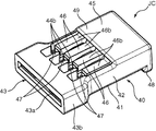
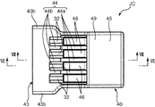
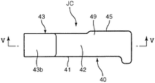
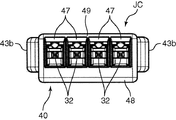
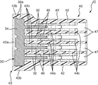
- FIG. 2 is a schematic plan view of FIG. 1. It is a schematic sectional drawing of FIG. It is a perspective view of the joint connector shown in FIG. It is a top view of the joint connector shown in FIG. It is a side view of the joint connector shown in FIG. It is a front view of the joint connector shown in FIG.
- FIG. 7 is a cross-sectional view taken along line VV in FIG. 6.
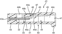
- FIG. 6 is a sectional view taken along line VI-VI in FIG. 5.
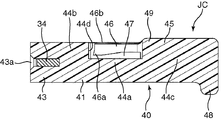
- FIG. 7 is a sectional view taken along line VII-VII in FIG. 5.
- FIG. 1 is a schematic perspective view showing a wire harness 100 according to this embodiment.
- 2 is a schematic plan view of FIG. 1
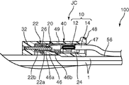
- FIG. 3 is a schematic cross-sectional view of FIG.
- a joint connector JC is wound around a trunk wire (wire harness body) 56 of a wire harness formed by bundling a plurality of electric wires 1 with a tape 58.
- the electric wire side terminals 20 provided respectively in the terminal of the multiple electric wires 10 of the electric wires 1 (four in the illustrated example) are short-circuited by the joint connector JC.
- 4 to 10 are diagrams showing the joint connector JC, respectively.
- each of the electric wires 10 includes a conductor 12 and an insulation coating 14 that covers the conductor 12.
- the terminal of each conductor 12 is exposed by removing the terminal of each insulation coating 14.
- the electric wire side terminal 20 is crimped to the end of each conductor 12.
- the electric wire side terminal 20 has a female electrical contact portion 22 and an electric wire crimping portion 24 at the front and rear.
- the female electrical contact portion 22 includes a hollow rectangular tube-shaped main body and a contact spring piece 26.
- the contact spring piece 26 has a shape that can be bent in the main body of the female electrical contact portion 22.
- the wire crimping portion 24 is crimped to the conductor 12 so as to embrace the end of the conductor 12, whereby the wire crimping portion 24 is electrically connected to the conductor 12.
- the joint connector JC includes a joint terminal 30 shown in FIG. 8 and the like, and a connector housing 40 for holding the joint terminal 30.
- the joint terminal 30 is made of a conductive material.
- the joint terminal 30 is commonly connected to the electric wire side terminals 20 to short-circuit the electric wire side terminals 20.
- the connector housing 40 is integrally formed of an insulating material such as synthetic resin.
- the connector housing 40 has a shape capable of holding the joint terminal 30 in a state of being stored inside.
- the joint terminal 30 is composed of a single metal plate.
- the joint terminal 30 integrally includes a plurality of electrical contact portions 32 and a short-circuit portion 34.
- the electrical contact portion 32 of each joint terminal 30 is a male type (tab) that can be fitted inside the female electrical contact portion 22 of each electric wire side terminal 20. These male electrical contacts 32 are arranged in a direction parallel to the width direction.
- the short circuit part 34 extends in the arrangement direction of the male electrical contact parts 32. The short ends 34 are connected to the base ends of the male electrical contacts 32.
- the connector housing 40 includes a flat main body wall 41, left and right side walls 42, 42, a terminal holding portion 43, a plurality of partition walls 44, an auxiliary wall 45, and a plurality of lances (terminal locking pieces) 46.
- the left and right side walls 42, 42 rise from both ends in the width direction of the main body wall 41.
- the terminal holding portion 43 is connected to rear ends (left ends in FIGS. 8 to 10) of the main body wall 41 and the side wall 42.
- the plurality of partition walls 44 project from the main body wall 41 to the inside of the connector housing.
- the plurality of lances 46 are connected to the auxiliary wall 45. At least one side surface of each of the main body wall 41, the side wall 42, the terminal holding portion 43, the partition wall 44 and the lance 46 is exposed to the outside, and constitutes an outer wall 49 of the connector housing 40.
- the terminal holding portion 43 holds the short-circuit portion 34 of the joint terminal 30.
- the terminal holding portion 43 is slightly larger than the short-circuit portion 34, extends in the arrangement direction of the male electrical contact portions 32 of the joint terminal 30, and the short-circuit portion 34 is inserted from the rear (left side in FIG. 8). It has a shape surrounding a possible joint terminal insertion opening 43a.
- the short-circuit portion 34 is press-fitted into the terminal holding portion 43 from the joint terminal insertion port 43a with the male electrical contact portions 32 facing forward, and is fixed in the joint terminal insertion port 43a.
- Protrusions 34 a as shown in FIG. 8 are formed at both ends in the width direction of the short-circuit portion 34.
- the short-circuit portion 34 is fixed in the joint terminal insertion port 43a in a state in which these protrusions 34a bite into the inner surface of the terminal holding portion 43.
- the width dimension of the terminal holding part 43 that is, the dimension in the arrangement direction of the joint terminals 30 is larger than the width dimension of other parts so that the terminal holding part 43 has sufficient strength to hold the short-circuit part 34. Large dimensions are set. In other words, at both ends in the width direction of the terminal holding portion 43, first protruding portions 43b that protrude outward from the outer surfaces of the left and right side walls 42 are formed.
- the male electrical contact portions 32 of the joint terminal 30 are arranged in a direction parallel to the width direction, and the terminal holding portion 43 also has a shape extending in the arrangement direction.
- the width dimension in the direction orthogonal to the arrangement direction is kept small.
- Each partition wall 44 is provided at a position interposed between the male electrical contact portions 32 adjacent to each other in a state where the joint terminal 30 is held by the terminal holding portion 43. These partition walls 44 protrude from the inner surface of the main body wall 41 to the inside of the connector housing 40 (upward in the posture of the joint connector JC shown in FIG. 9). These partition walls 44 continuously and linearly extend from the terminal holding portion 43 to the opposite end portion (front end portion of the connector housing 40).
- a terminal accommodating chamber 47 into which the wire-side terminal 20 connected to the male electrical contact portion 32 can be inserted is partitioned by the partition walls 44.
- These terminal accommodating chambers 47 are opened on the front end side of the connector housing 40 (on the side opposite to the terminal holding portion 43). The electric wire side terminal 20 is inserted into the terminal accommodating chamber 47 from each opening.
- each partition wall 44 has a central wall portion 44a, a rear side wall portion 44b, and a front side wall portion 44c.
- the central wall portion 44 a is interposed between the main body wall 41 and the lance 46.
- the rear side wall portion 44 b is interposed between the rear end of the lance 46 and the terminal holding portion 43.
- the front side wall portion 44c is connected to the auxiliary wall 45 at a position in front of the central wall portion 44a.
- the central wall portion 44a, the rear side wall portion 44b, and the front side wall portion 44c protrude from the inner surface of the main body wall 41 to the inside of the connector housing 40, respectively.
- the projecting dimension of the central wall 44 a from the main body wall 41 is smaller than the shortest distance from the main body wall 41 to the lance 46.
- the projecting dimensions of the rear side wall portion 44b and the front side wall portion 44c from the main body wall 41 are both larger than the shortest distance. Since the projecting dimension from the main body wall 41 is changed in this way, each partition wall 44 has an area where the lance 46 is present when viewed from a direction parallel to the arrangement direction of the male electrical contact portions 32. A rectangular notch 44d that avoids the above is formed.
- the auxiliary wall 45 is formed in a front portion of the connector housing 40 (a portion opposite to the terminal holding portion 43).
- the auxiliary wall 45 covers the side walls 42 and the partition walls 44 so as to cover the terminal accommodating chambers 47 from the side opposite to the body wall 41 (upper side in the posture of the joint connector JC shown in FIG. 9 and the like). Connected to. That is, each terminal accommodating chamber 47 is surrounded from four sides by the main body wall 41, the auxiliary wall 45, and the partition wall 44 or the side wall 42.
- Each lance 46 is inserted into the terminal accommodating chamber 47 to lock the electric wire side terminal 20 fitted to the male electrical contact portion 32.
- These lances 46 are provided for each of the terminal accommodating chambers 47.
- These lances 46 are formed integrally with the auxiliary wall 45 and have a shape extending rearwardly (in the direction toward the terminal holding portion 43) from the auxiliary wall 45, and are exposed to the outside so as to be connected to the connector housing 40.
- a part of the outer wall 49 is formed. Specifically, the outer surface 46b of each lance 46 opposite to the main body wall 41 is exposed to the outside.
- each lance 46 is formed integrally with the outer wall 49 of the connector housing 40, so that the lance 46 is placed inside the terminal accommodating chamber 47 such as the inner surface of the auxiliary wall 45. Compared with the case where it provides, the width dimension of the connector housing 40 is reduced.
- each lance 46 is in contact with a step portion 22a formed on the top wall 22b of the female electrical contact portion 22 of the electric wire side terminal 20 to lock each electric wire side terminal 20.
- Each part 46a is formed.
- Each locking portion 46a has a claw shape that can come into contact with the stepped portion 22a from the front side (right side in FIG. 3) of the connector housing 40.
- Each locking portion 46 a prevents the wire-side terminal 20 from coming out of the connector housing 40 by contact with the stepped portion 22 a.
- the end portion of each lance 46 in which the locking portion 46a is formed retreats outward from the main body wall 41 from the locking position at which the wire side terminal 20 is locked, and the locked state of the wire side terminal 20 is maintained. It is a free end that can be flexibly displaced toward the unlocking position to be released (downward in FIG. 3, upward in FIGS. 9 and 10).
- a second projecting portion 48 is formed which extends in the arrangement direction of the male electrical contact portions 32 of the joint terminal 30 and projects outward.
- the distance between the second protrusion 48 and the first protrusion 43b (the distance in the direction parallel to the insertion direction of the electric wire side terminal 20 into the connector housing 40) is set to be substantially equal to the width of the tape 58. Has been.
- the wire-side terminal 20 crimped to the end of the wire 10 is inserted into the terminal accommodating chamber 47. Specifically, the wire-side terminal 20 is inserted into the terminal accommodating chamber 47 while the lance 46 is moved from the locking position to the unlocking position by the top wall 22 b of the wire-side terminal 20.
- the electric wire side terminal 20 is inserted to a predetermined position, the stepped portion 22a of the electric wire side terminal 20 and the locking portion 46a of the lance 46 are engaged, and the lance 46 is elastic to the original position (locking position).
- the electric wire side terminal 20 and the electrical contact portion 32 of the joint terminal 30 are fitted, and the electric wire side terminal 20 and the joint terminal 30 are electrically connected.
- each electric wire side terminal 20 is inserted into the terminal accommodating chamber 47 and electrically connected to the joint terminal 30. Thereby, each electric wire side terminal 20 is mutually short-circuited via the joint terminal 30 (short circuit process).
- the outer peripheral surface of the trunk line 56 of the wire harness 100 is connected to the joint connector JC that is locked to the locking portion 46a of the lance 46 in a state where all the wire side terminals 20 are short-circuited as described above. Secure to.
- the side surface of the outer wall 49 of the connector housing 40 on the side where the lance 46 is formed face each other.
- the joint connector JC is installed on the outer peripheral surface of the trunk line 56 of the wire harness.
- the axial direction of the electric wire 10 and the axial direction of the main wire 56 of the wire harness are matched so that the electric wire 10 drawn from the main wire 56 of the wire harness is not twisted.
- the arrangement direction of the electrical contact portions 32 of the joint terminal 30 is orthogonal to the axial direction of each electric wire 10, and the amount of protrusion of the joint connector JC from the outer peripheral surface of the trunk line 56 of the wire harness is kept small.
- the width dimension of the connector housing 40 is kept small, and the protruding amount of the joint connector JC is kept small.
- the first protrusion 43b protrudes in the width direction of the main wire 56 of the wire harness, and the second protrusion 48 protrudes outward from the main wire 56 of the wire harness.
- the tape 58 is wound between the first protrusion 43b and the second protrusion 48 with the first protrusion 43b and the second protrusion 48 as a reference.
- the tape connector 58 fixes the joint connector JC to the outer peripheral surface of the main wire 56 of the wire harness.
- the outer surface 46b exposed to the outside of the lance 46 contacts the trunk line 56 of the wire harness, and the displacement of the lance 46 to the unlocking position is regulated by this contact (joint connector fixing step). ).
- the amount of protrusion of the joint connector JC from the main wire 56 of the wire harness is kept small, and the main wire 56 of the wire harness allows the displacement of the lance 46 to the unlocking position. By being restricted, the locking force of each electric wire side terminal 20 by these lances 46 is ensured.
- the distance between the first protrusion 43b and the second protrusion 48 is set to be approximately equal to the width of the tape 58, so that the first protrusion 43b and the second protrusion The tape 58 can be easily wound around the portion 48 as a reference. Further, since the displacement of the tape 58 is suppressed by the first protrusion 43b and the second protrusion 48, the joint connector JC is stably fixed on the outer peripheral surface of the trunk line 56 of the wire harness by the tape 58. .
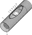
- the wire harness 100 is easily accommodated inside the corrugated pipe (protective pipe) 60 as shown in FIG. be able to.
- the corrugated pipe 60 is a pipe that can be bent and deformed along the trunk line 56 of the wire harness.
- FIG. 11 is a view in which a part of the corrugated pipe 60 is cut so that the inside can be seen. In actual use, the entire periphery of the wire harness 100 is covered with the corrugated pipe 60.
- the main wire 56 of the wire harness can be stored inside the corrugated pipe 60 with the joint connector JC fixed on the outer peripheral surface as described above, damage to the main wire 56 of the wire harness is applied to the joint connector JC. As a result, the disconnection of the electric wire side terminal 20 from the joint connector JC can be suppressed.
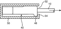
- the second protrusion 48 can function as a held portion held by a predetermined jig when testing the tensile strength of the electric wire 10 connected to the joint connector JC.
- a jig for performing this tensile test is shown in FIG.
- the jig 50 shown in FIG. 12 has a container shape that can store the entire joint connector JC. Further, the jig 50 is formed with a window 52 for leading the electric wire 10 connected to the joint connector JC to the outside of the jig 50. Further, an abutting wall 54 that can abut against the second protrusion 48 from the outside is formed at the peripheral edge of the window 52.
- the tensile test is performed when the joint connector JC is stored in the jig 50 and a tensile load is applied to the electric wire 10 in a state where the second projecting portion 48 and the contact wall 54 are in contact with each other. Is called.
- the contact between the second protrusion 48 and the contact wall 54 prevents the joint connector JC from being detached from the jig 50, and is appropriate for the electric wire 10 connected to the joint connector JC.
- a tensile load is applied.
- both the first protrusion 43b and the second protrusion 48 can be omitted. However, if the first protrusion 43b and the second protrusion 48 are provided, the tape 58 can be easily wound around the joint connector JC, and the position of the tape 58 can be stabilized. Further, as described above, the second protrusion 48 can function as the held portion during a tensile test.
- the specific shape of the first protrusion 43b is not limited to the above. However, if the width dimension of the terminal holding portion 43 is set large and the first projecting portion 43b is formed by both ends in the width direction, the holding force of the joint terminal 30 by the terminal holding portion 43 is ensured. In addition, an effect such as positioning of the tape 58 can be obtained without providing the first protrusion 43b separately.
- the number of electric wires 10 to be short-circuited is not limited to the above.
- the present invention is a joint connector for electrically short-circuiting a wire harness main body composed of a plurality of electric wires and a plurality of electric wire side terminals respectively provided at terminals of the plurality of electric wires included in the wire harness main body.
- a wire harness comprising: a joint terminal that contacts each of the electric wire side terminals and short-circuits the electric wire side terminals; and the joint terminal and the electric wire side terminals are accommodated inside, respectively.
- a connector housing that is held in a state, and the joint terminal has a shape that can be in contact with each of the electric wire side terminals and is arranged in a direction substantially orthogonal to the axial direction of the electric wires connected to the electric wire side terminals.
- An electrical contact portion and a short-circuit portion extending in the arrangement direction of the electrical contact portions and connected to each electrical contact portion are integrally provided, and
- the nectar housing surrounds a terminal accommodating chamber that accommodates each electric wire side terminal and is exposed to the outside, and the electric wire side terminal that is integrally formed on the outer wall and accommodated in the terminal accommodating chamber contacts the joint terminal.
- a plurality of terminal locking pieces which are respectively locked in the state where the terminal locking pieces are retracted to the outside of the outer wall from the locking positions and the locking positions of the electric wire side terminals.
- the joint connector has a shape that can be bent and displaced with respect to an unlocking position for releasing the locking state of the electric wire side terminal, and the joint connector has an outer surface of the outer wall of the connector housing on which the terminal locking piece is formed.
- a wire harness that is fixed on the outer peripheral surface of the wire harness body in a posture that faces the outer peripheral surface of the wire harness body and contacts the outer peripheral surface.
- the joint connector is provided on the outer peripheral surface of the wire harness main body, and each electric wire side terminal is connected to each electric contact portion of the joint terminal of the joint connector.
- the electric wire side terminals of the plurality of electric wires included in the wire harness main body can be short-circuited via the short-circuit portion connected to.
- the joint terminals are arranged in a direction substantially orthogonal to the axial direction of the electric wire, and the thickness of the joint connector in the direction orthogonal to the axial direction of the electric wire and the arrangement direction of the joint terminal is suppressed to be small. Is done.
- the terminal locking piece is formed integrally with the outer wall of the connector housing exposed to the outside, and as disclosed in Japanese Patent Application Laid-Open No. 2005-50794, a terminal accommodating chamber surrounded by the outer wall of the connector housing.
- the thickness of the joint connector that is, the amount of protrusion from the wire harness main body is suppressed to be smaller than that in the case where the terminal locking pieces are provided on the inner side. This realizes miniaturization of the wire harness.
- the outer surface of the outer wall on which the terminal locking piece is formed is opposed to and in contact with the outer peripheral surface of the wire harness body, and the displacement of the terminal locking piece is regulated by the wire harness body.
- the locking force of each electric wire side terminal by the terminal locking piece can be maintained with a simple structure without adding a special member.
- a tape for fixing the joint connector on the outer peripheral surface of the wire harness main body is provided, and the connector housing is a side surface excluding a side surface of the outer wall facing the outer peripheral surface of the wire harness main body.
- a first protrusion and a second protrusion protruding outward from the first protrusion and the second protrusion are separated by a distance substantially equal to the width of the tape, It is preferable that the wire is wound around a region between the first protrusion and the second protrusion.
- Such a configuration realizes winding of the tape based on the first protrusion and the second protrusion, and facilitates winding of the tape around the wire harness body.
- these 1st protrusion parts and 2nd protrusion parts suppress the shift
- the first projecting portion is constituted by a portion surrounding the short-circuit portion of the joint terminal.
- Such a configuration realizes widening of the portion surrounding the short-circuit portion to ensure strength for holding the short-circuit portion, and avoids separately providing the first protrusion.
- a wire harness main body as mentioned above, it comprises the corrugated pipe (protective pipe) which can be bent and deformed along the said wire harness main body,
- the said corrugated pipe (protective pipe) A wire harness characterized in that the wire harness main body and a joint connector fixed on the outer peripheral surface of the wire harness main body are accommodated inside the wire harness can be provided.
- the present invention provides a short-circuiting step for electrically short-circuiting a plurality of electric wire side terminals respectively provided at ends of a plurality of electric wires included in the wire harness main body using a joint connector;
- a joint connector fixing step for fixing to the outer surface of the harness body, and the joint connector used for short-circuiting the wire-side terminals in the short-circuiting step is brought into contact with each wire-side terminal,
- a joint terminal that holds the joint terminal and the electric wire side terminals in a state of being accommodated inside, and the joint terminal has a shape that can contact the electric wire side terminals.
- a plurality of electrical contacts arranged in a direction substantially orthogonal to the axial direction of the electric wire connected to the electric wire side terminal.
- a short-circuit portion that extends in the arrangement direction of the electrical contact portions and is connected to each electrical contact portion, and the connector housing surrounds a terminal accommodating chamber that accommodates each of the electric wire side terminals and is exposed to the outside.
- An outer wall, and a plurality of terminal locking pieces that are integrally formed on the outer wall and that lock each electric wire side terminal accommodated in the terminal accommodating chamber in contact with the joint terminal.
- the locking piece can be flexibly displaced between a position where the electric wire side terminal is locked and an unlocking position where the electric wire side terminal is released from the locking position to the outside of the outer wall.
- each wire-side terminal is inserted into the terminal accommodating chamber, and the wire-side terminal is locked by the terminal locking piece at a position in contact with the joint terminal.
- the connector fixing step after all the electric wire side terminals are inserted into the terminal accommodating chamber and locked by the terminal locking pieces, the outer wall of the connector housing on which the terminal locking pieces are formed is formed.
- the joint connector is fixed onto the outer peripheral surface of the wire harness body in a state where the outer surface is opposed to the outer peripheral surface of the wire harness body and is in contact with the outer peripheral surface.
- each wire-side terminal is locked by each terminal locking piece and each wire-side terminal is short-circuited, and then in the joint connector fixing step, the joint connector is The outer surface of the outer wall of the connector housing on which the terminal locking piece is formed is fixed on the outer peripheral surface of the wire harness body so as to face and contact the outer peripheral surface of the wire harness body. Can be reliably short-circuited, and the displacement of each terminal locking piece can be restricted to lock each wire-side terminal more reliably.
Landscapes
- Connector Housings Or Holding Contact Members (AREA)
Abstract
Priority Applications (3)
| Application Number | Priority Date | Filing Date | Title |
|---|---|---|---|
| DE112009000065.7T DE112009000065B4 (de) | 2008-01-17 | 2009-01-13 | Kabelbaum |
| US12/597,549 US7806720B2 (en) | 2008-01-17 | 2009-01-13 | Wire harness and wire harness assembling method |
| CN2009800005286A CN101689740B (zh) | 2008-01-17 | 2009-01-13 | 线束和线束组装方法 |
Applications Claiming Priority (2)
| Application Number | Priority Date | Filing Date | Title |
|---|---|---|---|
| JP2008-007891 | 2008-01-17 | ||
| JP2008007891A JP5033651B2 (ja) | 2008-01-17 | 2008-01-17 | ワイヤハーネス及びワイヤハーネス組立方法 |
Publications (1)
| Publication Number | Publication Date |
|---|---|
| WO2009090942A1 true WO2009090942A1 (fr) | 2009-07-23 |
Family
ID=40885331
Family Applications (1)
| Application Number | Title | Priority Date | Filing Date |
|---|---|---|---|
| PCT/JP2009/050327 Ceased WO2009090942A1 (fr) | 2008-01-17 | 2009-01-13 | Faisceau de fils et procédé d'assemblage de faisceau de fils |
Country Status (5)
| Country | Link |
|---|---|
| US (1) | US7806720B2 (fr) |
| JP (1) | JP5033651B2 (fr) |
| CN (1) | CN101689740B (fr) |
| DE (1) | DE112009000065B4 (fr) |
| WO (1) | WO2009090942A1 (fr) |
Cited By (2)
| Publication number | Priority date | Publication date | Assignee | Title |
|---|---|---|---|---|
| CN102598152A (zh) * | 2010-02-17 | 2012-07-18 | 株式会社自动网络技术研究所 | 包括短路电路的线束及其制造方法 |
| WO2012111600A1 (fr) * | 2011-02-15 | 2012-08-23 | 矢崎総業株式会社 | Cosse de raccordement |
Families Citing this family (16)
| Publication number | Priority date | Publication date | Assignee | Title |
|---|---|---|---|---|
| JP5838821B2 (ja) * | 2012-01-16 | 2016-01-06 | 住友電装株式会社 | コネクタセットの固定方法 |
| JP2014013682A (ja) * | 2012-07-04 | 2014-01-23 | Yazaki Corp | コネクタ用ハウジング |
| JP5825529B2 (ja) * | 2012-11-19 | 2015-12-02 | 株式会社オートネットワーク技術研究所 | 電子部品ユニット及びワイヤーハーネスシステム |
| JP6315341B2 (ja) * | 2014-12-15 | 2018-04-25 | 株式会社オートネットワーク技術研究所 | 車載ネットワークにおける幹線構造、及び車載ネットワーク用コネクタ |
| JP6206392B2 (ja) * | 2014-12-25 | 2017-10-04 | 株式会社オートネットワーク技術研究所 | ジョイントコネクタ |
| JP2016207487A (ja) * | 2015-04-23 | 2016-12-08 | 株式会社オートネットワーク技術研究所 | ジョイントコネクタ |
| JP6372428B2 (ja) * | 2015-06-22 | 2018-08-15 | 株式会社オートネットワーク技術研究所 | ジョイントコネクタ |
| CN106058528B (zh) * | 2016-05-20 | 2019-07-26 | 中航光电科技股份有限公司 | 一种电连接器接触件、电连接器及短接电连接器 |
| JP6912275B2 (ja) * | 2017-01-27 | 2021-08-04 | 矢崎総業株式会社 | コネクタハウジング及びコネクタユニット |
| US10305232B2 (en) | 2017-01-27 | 2019-05-28 | Yazaki Corporation | Connector housing and connector unit |
| JP6959036B2 (ja) * | 2017-06-01 | 2021-11-02 | 矢崎総業株式会社 | コネクタハウジング |
| CN108445346A (zh) * | 2018-04-08 | 2018-08-24 | 安徽华菱汽车有限公司 | 一种发动机线束短路的检查装置及方法 |
| US10704710B2 (en) * | 2018-11-20 | 2020-07-07 | The Boeing Company | Easy lock P-clamp |
| JP7123858B2 (ja) * | 2019-05-24 | 2022-08-23 | 矢崎総業株式会社 | コネクタ及びワイヤーハーネス |
| JP2024167721A (ja) * | 2023-05-22 | 2024-12-04 | 矢崎総業株式会社 | バスバー製造方法 |
| CN119787049A (zh) * | 2023-12-06 | 2025-04-08 | 国网浙江省电力有限公司湖州供电公司 | 一种设有磁吸头的二次短接线 |
Citations (3)
| Publication number | Priority date | Publication date | Assignee | Title |
|---|---|---|---|---|
| JP2000173352A (ja) * | 1998-12-01 | 2000-06-23 | Sumitomo Wiring Syst Ltd | ジョイントコネクタ及びこれを用いたワイヤハーネスの組立方法 |
| JP2004014220A (ja) * | 2002-06-05 | 2004-01-15 | Sumitomo Wiring Syst Ltd | ジョイントコネクタ |
| JP2006049199A (ja) * | 2004-08-06 | 2006-02-16 | Sumitomo Wiring Syst Ltd | ワイヤーハーネス |
Family Cites Families (14)
| Publication number | Priority date | Publication date | Assignee | Title |
|---|---|---|---|---|
| DE4407083C2 (de) * | 1993-03-03 | 1998-10-08 | Sumitomo Wiring Systems | Steckverbindergehäuse und zugehöriger Steckverbinder |
| JPH0878117A (ja) * | 1994-08-31 | 1996-03-22 | Yazaki Corp | ジョイントコネクタ |
| JPH104619A (ja) * | 1996-06-13 | 1998-01-06 | Sumitomo Wiring Syst Ltd | プロテクタ |
| DE19702373B4 (de) * | 1997-01-23 | 2008-02-21 | The Whitaker Corp., Wilmington | Elektrischer Steckverbinder mit einer Kurzschlußfeder und Kurzschlußfeder |
| JPH10214651A (ja) * | 1997-01-29 | 1998-08-11 | Sumitomo Wiring Syst Ltd | ジョイントコネクタのワイヤハーネスへの固定構造 |
| JP3362103B2 (ja) * | 1997-03-14 | 2003-01-07 | 矢崎総業株式会社 | ジョイントコネクタ |
| EP1030411A1 (fr) * | 1999-02-16 | 2000-08-23 | Sumitomo Wiring Systems, Ltd. | Connecteur de raccordement |
| JP2001245426A (ja) * | 2000-02-29 | 2001-09-07 | Sumitomo Wiring Syst Ltd | クランプおよび該クランプを用いたワイヤハーネスへのコネクタ固定構造 |
| JP4519539B2 (ja) | 2003-07-17 | 2010-08-04 | 株式会社オートネットワーク技術研究所 | ワイヤハーネス用ジョイントコネクタ |
| US7351085B2 (en) | 2003-07-17 | 2008-04-01 | Autonetworks Technologies, Ltd. | Joint member and joint connector for wire harness |
| JP2006253017A (ja) * | 2005-03-11 | 2006-09-21 | Sumitomo Wiring Syst Ltd | ジョイントコネクタ |
| JP4533825B2 (ja) * | 2005-09-05 | 2010-09-01 | 矢崎総業株式会社 | コネクタ |
| US7641500B2 (en) * | 2007-04-04 | 2010-01-05 | Fci Americas Technology, Inc. | Power cable connector system |
| US7690927B1 (en) * | 2009-03-19 | 2010-04-06 | International Business Machines Corporation | Processor scaling across multiple computer blades |
-
2008
- 2008-01-17 JP JP2008007891A patent/JP5033651B2/ja active Active
-
2009
- 2009-01-13 WO PCT/JP2009/050327 patent/WO2009090942A1/fr not_active Ceased
- 2009-01-13 US US12/597,549 patent/US7806720B2/en active Active
- 2009-01-13 CN CN2009800005286A patent/CN101689740B/zh active Active
- 2009-01-13 DE DE112009000065.7T patent/DE112009000065B4/de active Active
Patent Citations (3)
| Publication number | Priority date | Publication date | Assignee | Title |
|---|---|---|---|---|
| JP2000173352A (ja) * | 1998-12-01 | 2000-06-23 | Sumitomo Wiring Syst Ltd | ジョイントコネクタ及びこれを用いたワイヤハーネスの組立方法 |
| JP2004014220A (ja) * | 2002-06-05 | 2004-01-15 | Sumitomo Wiring Syst Ltd | ジョイントコネクタ |
| JP2006049199A (ja) * | 2004-08-06 | 2006-02-16 | Sumitomo Wiring Syst Ltd | ワイヤーハーネス |
Cited By (4)
| Publication number | Priority date | Publication date | Assignee | Title |
|---|---|---|---|---|
| CN102598152A (zh) * | 2010-02-17 | 2012-07-18 | 株式会社自动网络技术研究所 | 包括短路电路的线束及其制造方法 |
| CN102598152B (zh) * | 2010-02-17 | 2014-10-22 | 株式会社自动网络技术研究所 | 包括短路电路的线束及其制造方法 |
| WO2012111600A1 (fr) * | 2011-02-15 | 2012-08-23 | 矢崎総業株式会社 | Cosse de raccordement |
| JP2012169186A (ja) * | 2011-02-15 | 2012-09-06 | Yazaki Corp | ジョイントコネクタ |
Also Published As
| Publication number | Publication date |
|---|---|
| CN101689740B (zh) | 2011-11-30 |
| US7806720B2 (en) | 2010-10-05 |
| US20100144193A1 (en) | 2010-06-10 |
| CN101689740A (zh) | 2010-03-31 |
| DE112009000065B4 (de) | 2017-11-23 |
| JP5033651B2 (ja) | 2012-09-26 |
| DE112009000065T5 (de) | 2011-02-17 |
| JP2009170289A (ja) | 2009-07-30 |
Similar Documents
| Publication | Publication Date | Title |
|---|---|---|
| JP5033651B2 (ja) | ワイヤハーネス及びワイヤハーネス組立方法 | |
| CN102282732B (zh) | 接地用连接器及包含该接地用连接器的线束 | |
| JP5129880B2 (ja) | コネクタ端子及び該コネクタ端子を備えたコネクタ | |
| US9401550B2 (en) | Connector | |
| US9368906B2 (en) | Electric terminal | |
| JP2009151942A (ja) | ジョイントコネクタ及びこれを用いた電線短絡方法 | |
| WO2014030626A1 (fr) | Composant électronique, structure de raccordement de composant électronique et de raccord de borne, et boîtier de raccordement électrique doté d'un composant électronique | |
| US20170117675A1 (en) | Electric connector | |
| JP5414836B2 (ja) | コネクタ | |
| JP4891850B2 (ja) | ジョイントコネクタ | |
| US10756478B2 (en) | Terminal and method of connecting electric wire to terminal | |
| EP3671959B1 (fr) | Connecteur | |
| JP6768304B2 (ja) | コネクタの組立方法 | |
| JP4457862B2 (ja) | コネクタ | |
| JP7827540B2 (ja) | フラットケーブル用コネクタ | |
| US10756450B2 (en) | Terminal and electric wire with the same | |
| JP2012243562A (ja) | コネクタ端子及びこのコネクタ端子を含むカードエッジ型コネクタ | |
| JP7287771B2 (ja) | コネクタ、及び、カバー | |
| CN113875096B (zh) | 连接器 | |
| JP5365093B2 (ja) | 短絡回路を含むワイヤハーネス | |
| JP2010067405A (ja) | 短絡回路を含むワイヤハーネス及びその製造方法 | |
| KR101175571B1 (ko) | 전기 커넥터 | |
| JP2010067406A (ja) | 短絡回路を含むワイヤハーネス及びその製造方法 | |
| JP2002184508A (ja) | コネクタ | |
| JP2004055391A (ja) | フラット配線材用コネクタ |
Legal Events
| Date | Code | Title | Description |
|---|---|---|---|
| WWE | Wipo information: entry into national phase |
Ref document number: 200980000528.6 Country of ref document: CN |
|
| 121 | Ep: the epo has been informed by wipo that ep was designated in this application |
Ref document number: 09702165 Country of ref document: EP Kind code of ref document: A1 |
|
| WWE | Wipo information: entry into national phase |
Ref document number: 12597549 Country of ref document: US |
|
| WWE | Wipo information: entry into national phase |
Ref document number: 8300/DELNP/2009 Country of ref document: IN |
|
| WWE | Wipo information: entry into national phase |
Ref document number: 1120090000657 Country of ref document: DE |
|
| RET | De translation (de og part 6b) |
Ref document number: 112009000065 Country of ref document: DE Date of ref document: 20110217 Kind code of ref document: P |
|
| 122 | Ep: pct application non-entry in european phase |
Ref document number: 09702165 Country of ref document: EP Kind code of ref document: A1 |