WO2009091006A1 - Projecteur de lumière pour véhicule à enfourcher et véhicule à enfourcher - Google Patents
Projecteur de lumière pour véhicule à enfourcher et véhicule à enfourcher Download PDFInfo
- Publication number
- WO2009091006A1 WO2009091006A1 PCT/JP2009/050486 JP2009050486W WO2009091006A1 WO 2009091006 A1 WO2009091006 A1 WO 2009091006A1 JP 2009050486 W JP2009050486 W JP 2009050486W WO 2009091006 A1 WO2009091006 A1 WO 2009091006A1
- Authority
- WO
- WIPO (PCT)
- Prior art keywords
- wall
- housing
- cover
- lens
- attached
- Prior art date
- Legal status (The legal status is an assumption and is not a legal conclusion. Google has not performed a legal analysis and makes no representation as to the accuracy of the status listed.)
- Ceased
Links
Images



Classifications
-
- B—PERFORMING OPERATIONS; TRANSPORTING
- B62—LAND VEHICLES FOR TRAVELLING OTHERWISE THAN ON RAILS
- B62J—CYCLE SADDLES OR SEATS; AUXILIARY DEVICES OR ACCESSORIES SPECIALLY ADAPTED TO CYCLES AND NOT OTHERWISE PROVIDED FOR, e.g. ARTICLE CARRIERS OR CYCLE PROTECTORS
- B62J6/00—Arrangement of optical signalling or lighting devices on cycles; Mounting or supporting thereof; Circuits therefor
- B62J6/04—Rear lights
-
- B—PERFORMING OPERATIONS; TRANSPORTING
- B60—VEHICLES IN GENERAL
- B60Q—ARRANGEMENT OF SIGNALLING OR LIGHTING DEVICES, THE MOUNTING OR SUPPORTING THEREOF OR CIRCUITS THEREFOR, FOR VEHICLES IN GENERAL
- B60Q1/00—Arrangement of optical signalling or lighting devices, the mounting or supporting thereof or circuits therefor
- B60Q1/26—Arrangement of optical signalling or lighting devices, the mounting or supporting thereof or circuits therefor the devices being primarily intended to indicate the vehicle, or parts thereof, or to give signals, to other traffic
- B60Q1/2657—Arrangement of optical signalling or lighting devices, the mounting or supporting thereof or circuits therefor the devices being primarily intended to indicate the vehicle, or parts thereof, or to give signals, to other traffic mounted on a shaft, e.g. telescopic
-
- F—MECHANICAL ENGINEERING; LIGHTING; HEATING; WEAPONS; BLASTING
- F21—LIGHTING
- F21S—NON-PORTABLE LIGHTING DEVICES; SYSTEMS THEREOF; VEHICLE LIGHTING DEVICES SPECIALLY ADAPTED FOR VEHICLE EXTERIORS
- F21S43/00—Signalling devices specially adapted for vehicle exteriors, e.g. brake lamps, direction indicator lights or reversing lights
- F21S43/20—Signalling devices specially adapted for vehicle exteriors, e.g. brake lamps, direction indicator lights or reversing lights characterised by refractors, transparent cover plates, light guides or filters
- F21S43/27—Attachment thereof
-
- F—MECHANICAL ENGINEERING; LIGHTING; HEATING; WEAPONS; BLASTING
- F21—LIGHTING
- F21W—INDEXING SCHEME ASSOCIATED WITH SUBCLASSES F21K, F21L, F21S and F21V, RELATING TO USES OR APPLICATIONS OF LIGHTING DEVICES OR SYSTEMS
- F21W2103/00—Exterior vehicle lighting devices for signalling purposes
- F21W2103/20—Direction indicator lights
Definitions
- the present invention relates to a floodlight device for a saddle-ride type vehicle, for example, a floodlight device for a saddle-ride type vehicle that can be applied to a flasher (rear flasher) attached to the rear portion of the saddle-ride type vehicle.
- a floodlight device for a saddle-ride type vehicle for example, a floodlight device for a saddle-ride type vehicle that can be applied to a flasher (rear flasher) attached to the rear portion of the saddle-ride type vehicle.
- a flasher (rear flasher) attached to a saddle-ride type vehicle is disclosed in, for example, Japanese Patent Laid-Open No. 2005-235622 (Patent Document 1).
- the flasher attached to the saddle-ride type vehicle shields the space where the light bulb is disposed so as not to be exposed to rainwater.
- a light projecting device for a saddle-ride type vehicle shields a space where a light bulb is disposed, but water may enter outside the shielded space.
- a cover that covers the outside of the shielded space may be provided, and a lens edge may be attached to the cover. In this case, when water enters the cover and water accumulates at the edge of the lens, it may appear that water has entered the lens.
- the light-projecting device for a saddle-ride type vehicle includes a lens having a cover mounting portion provided at the peripheral portion and a housing mounting portion provided inward of the cover mounting portion.
- the light-projecting device for the saddle-ride type vehicle includes a light bulb disposing portion that faces the lens, has an opening edge attached to the housing attaching portion, and has a light source disposed in a space defined by the lens and the housing. And a cover that covers the outside of the housing and is attached to the cover attachment portion. Further, an opaque region in which the lens is opaque is provided between the cover mounting portion and the housing mounting portion.
- the light projection device for a saddle-ride type vehicle since the opaque region described above is provided, even if water enters between the cover mounting portion and the housing mounting portion, the space defined by the lens and the housing It doesn't look like water is inside.
- FIG. 1 is a right side view of a saddle riding type vehicle according to an embodiment of the present invention.
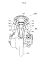
- FIG. 2 is a rear view of the saddle riding type vehicle according to the embodiment of the present invention.
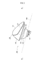
- FIG. 3 is a perspective view showing a flasher of the saddle riding type vehicle according to the embodiment of the present invention.
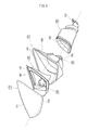
- FIG. 4 is an exploded perspective view of the flasher according to the embodiment of the present invention.
- FIG. 5 is an exploded perspective view of the flasher according to the embodiment of the present invention.
- FIG. 6 is a cross-sectional view of a flasher according to an embodiment of the present invention.
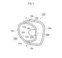
- FIG. 7 is a cross-sectional view of a flasher according to another embodiment of the present invention.
- the saddle riding type vehicle 1000 is a scooter type motorcycle as shown in FIG. 1, and a vehicle body cover 400 made of resin is attached to a body frame (not shown).
- the saddle riding type vehicle 1000 is provided with a tail lamp 103 mainly functioning as a brake lamp and a flasher 101 mainly functioning as a direction indicator light at the rear part.
- FIG. 2 is a drawing of the saddle riding type vehicle 1000 as viewed from the rear, but the drawing is partially simplified for the sake of convenience, and in particular, the components in the vehicle body cover 400 are not shown.
- the exterior members of the vehicle body cover 400, the tail lamp 103, and the flasher 101 are substantially attached to the vehicle body frame (not shown) via brackets. As a result, these exterior members have a required mounting strength so that they do not rattle due to traveling wind or vibration during traveling.
- the tail lamp 103 is mounted on the vehicle body cover 400 at the rear of the vehicle.
- the flasher 101 is separate from the tail lamp 103 and is disposed on both sides in the vehicle width direction at the rear of the vehicle.
- a mudguard member 502 (rear fender) is disposed after the rear wheel 501.
- the flasher 101 has a leg portion 180, and is attached to the base end portion 503 of the mudguard member 502 via the leg portion 180.
- the flasher 101 includes a lens 120, a housing 140, a cover 160, and a leg portion 180.
- the lens 120 is provided with a cover attachment portion 124 at the peripheral portion, and a housing attachment portion 123 inside the cover attachment portion 124. That is, in this embodiment, the lens 120 is formed of a transparent resin (in this embodiment, methacryl (PMMA)), and has a transparent lens surface 121.
- the lens 120 is provided with a cover attachment portion 124 to which the cover 160 is attached and a housing attachment portion 123 to which the housing 140 is attached at the periphery.
- the housing attachment portion 123 is provided inside the cover attachment portion 124 to which the cover 160 is attached.
- an opaque region a in which the lens is opaque is formed between a cover attachment portion 124 to which the cover 160 is attached and a housing attachment portion 123 to which the housing 140 is attached.
- an inner wall 123 and an outer wall 124 are formed on the periphery of the lens 120.
- the housing 140 is attached to the inner wall 123 and the cover 160 is attached to the outer wall 124.
- An opaque region a is formed on the outer wall 124.
- the opaque region a may be formed by such painting, for example. For example, it may be painted with black paint.
- the inner side surface 122 between the inner wall 123 and the outer wall 124 is painted with an opaque paint as an opaque region. In this case, for example, it may be painted with a black paint.
- the side surface 122 between the inner wall 123 and the outer wall 124 is painted with black paint over the entire circumference of the lens 120.
- the housing 140 faces the lens 120, and an opening edge 141 (outer edge) is attached to the housing attachment portion 123.
- the housing 140 has a light bulb arrangement portion 143 in which a light bulb 250 (bulb, see FIG. 6) as a light source is arranged in a space 130 defined by the lens 120 and the housing 140. . That is, the light bulb 250 as a light source is attached in a space 130 defined by the lens 120 and the housing 140.
- the housing 140 is provided with a light bulb 250 as a light source.
- the housing 140 is a housing (casing) in which the light bulb 250 is disposed, and has a shape in which the side facing the lens 120 is generally recessed.
- the housing 140 is made of resin (in this embodiment, polycarbonate (PC)), and a surface 142 facing the lens 120 is mirror-finished, and the surface 142 constitutes a reflector.
- the housing 140 also serves as a reflector.
- the mirror finish is preferably performed by metal vapor deposition, for example.
- the light bulb 250 is arranged with the light emitting portion 252 facing the lens surface 121, and the socket 251 is fixed to the light bulb arranging portion 143.
- the opening edge 141 of the housing 140 is attached to a housing attachment portion 123 (inner wall 123) provided inside the peripheral edge of the lens 120. More specifically, in this embodiment, as shown in FIG. 6, the edge of the inner wall 123 of the lens 120 and the opening edge 141 of the housing 140 are attached in contact with each other. Furthermore, the opening edge 141 of the housing 140 and the housing attachment portion 123 of the lens 120 are attached in a watertight manner by welding.
- the cover 160 covers the outside of the housing 140 and is attached to the cover attachment portion 124.
- the cover 160 is a member that covers the outside of the housing 140 and is attached to the outer wall 124 of the lens 120.
- the outer edge 161 of the cover 160 is attached to a cover attaching portion 124 (outer wall 124) provided at the peripheral edge of the lens 120. More specifically, in this embodiment, the edge of the outer wall 124 of the lens 120 and the outer edge 161 of the cover 160 are attached in contact with each other.
- the abutting portion q between the inner wall 123 of the lens 120 and the opening edge 141 of the housing 140 and the abutting portion r between the outer wall 124 of the lens 120 and the outer edge 161 of the cover 160 are provided. , They are deviated from the direction in which they abut each other.
- the cover 160 is made of resin (in this embodiment, polypropylene (PP)), and an opening through which the electric wiring 253 (see FIG. 6) of the light bulb 250 passes. 164 is formed.
- a mounting portion 166 for attaching the leg portion 180 is provided around the opening 164 on the outer surface of the cover 160.
- a rotation stopper 168 is provided around the attachment portion 166.
- the rotation stopper 168 is provided with an engagement piece along a portion of the ellipse that has a sharp curve where the major axes intersect.
- the leg portion 180 is a cylindrical member.
- One end 181 of the leg portion 180 is attached to the vehicle body cover 400 (see FIG. 2), and the other end 182 of the leg portion 180 is a flasher.
- 101 is attached to a mounting portion 166 of the cover 160.
- a rotation stopper 168 is provided on the mounting portion 166.
- the cover 160 of the flasher 101 is attached to the other end 182 of the leg portion 180 by engaging with the rotation stopper 168. Thereby, the cover 160 and the leg part 180 are fitted together.
- the leg part 180 is good to shape
- the electric wiring 253 to the light bulb of the flasher 101 is not shown, but is passed through the inside of the vehicle body cover 400 from the light bulb arrangement portion 143 of the housing 140 through the inside of the cover 160 and the leg portion 180.
- the battery (not shown) of the saddle riding type vehicle 1000 is electrically connected.
- the flasher 101 reflects the light projected from the bulb directly or inside the housing 140 and illuminates the outside of the lens 120 through the transparent lens surface 121 of the lens 120.
- the light direction of the flasher 101 is adjusted by the housing 140 or the like so that it can be seen from a predetermined area outside the flasher 101.
- the flasher 101 as the light projecting device includes the lens 120, the housing 140, and the cover 160.
- the lens 120 is provided with a cover mounting portion 124 at the periphery.
- a housing attachment portion 123 is provided inward of the cover attachment portion 124.
- the housing 140 faces the lens 120, and an opening edge 141 is attached to the housing attachment portion 123.
- the housing 140 also has a light bulb arrangement portion 143 in which a light bulb 250 as a light source is arranged in a space 130 defined by the lens 120 and the housing 140.
- the cover 160 covers the outside of the housing 140 and is attached to the cover attachment portion 124. Further, an opaque region a in which the lens 120 is made opaque is provided between the cover mounting portion 124 and the housing mounting portion 123.
- the flasher 101 since the above-described opaque region a is provided, even if water enters the space 122 between the cover attachment portion 124 and the housing attachment portion 123, the space 130 defined by the lens 120 and the housing 140 is obtained. It doesn't look like water is inside.
- the flasher 101 has the cover 160 attached to the peripheral portion of the lens 120 and the housing 140 attached to the inner periphery of the cover 160 at the peripheral portion of the lens 120. It has been.
- the lens 120 has an opaque region a formed between the cover 160 and the housing 140. Further, as an opaque region, the inner side surface 122 between the inner wall 123 and the outer wall 124 is painted with an opaque paint. For this reason, even when water enters the inside of the cover 160 at the periphery of the lens 120, the water cannot be seen from the outside.
- the opaque region is formed by painting.
- the construction of the opaque region is easy.
- the peripheral edge of the lens 120 can be assimilated to the color of the surrounding cover 160 to produce a sharp impression on the lens 120 of the flasher 101.
- an impression that the lens 120 of the flasher 101 stands out can be produced.
- the color of the cover 160 is black, and a sharp impression is produced on the lens 120 by painting in black.
- the inner side surface 122 between the inner wall 123 and the outer wall 124 is painted with an opaque paint, but the portion to be painted is not limited to this.
- the outer side surface of the outer wall 124 may be painted with an opaque paint.
- the inner side surface 122 between the inner wall 123 and the outer wall 124 only the outer wall 124 may be painted, or only the inner wall 123 may be painted. In this case, only the inner side surface of the outer wall 124 may be painted, or only the outer side surface of the outer wall 124 may be painted. Further, only the inner side surface of the inner wall 123 may be painted, or only the outer side surface of the inner wall 123 may be painted.
- the peripheral edge of the lens 120 is painted over the entire circumference.
- an opaque region can be formed over the entire periphery of the periphery of the lens 120.
- the periphery of the lens 120 is painted over the entire periphery, but a part of the lens 120 (for example, when water enters the inside of the cover 160 at the periphery of the lens 120). Only the part where the water tends to accumulate may be painted.
- the opaque region can be realized by other than painting.
- a sticker may be attached to the peripheral edge of the lens. In this case, the design of the flasher 101 can be improved by the color of the seal as in the case of painting.
- sticker may stick a seal
- a seal may be applied only to the outer wall 124 of the inner side surface 122 between the inner wall 123 and the outer wall 124, or a seal may be applied only to the inner wall 123.
- a seal may be further applied only to the inner side surface of the outer wall 124, or a seal may be applied only to the outer side surface of the outer wall 124.
- a seal may be applied only to the inner side surface of the inner wall 123, or a seal may be applied only to the outer side surface of the inner wall 123.
- the means for forming the opaque region is not limited to painting or sticking a seal.
- the lens 120 and the housing 140 are watertightly attached by welding, it is possible to prevent water from entering the space 130 in which the light bulb 250 is disposed.
- the housing 140 and the lens 120 are separate, but the housing 140 and the cover 160 may be formed as an integral member.
- the housing 140 and the cover 160 are formed as an integral member, it is possible to more reliably prevent water from entering the space 130 defined by the lens 120 and the housing 140.
- an inner wall 123 and an outer wall 124 are formed at the periphery of the lens 120, the housing 140 is attached to the inner wall 123, and the cover 160 is attached to the outer wall 124. It is attached. For this reason, water entering the inside of the cover 160 enters between the inner wall 123 and the outer wall 124, so that water enters the inside of the inner wall 123, that is, the space 130 in which the light bulb 250 is disposed. Can be prevented.
- the inner wall 123 and the housing 140, and the outer wall 124 and the cover 160 are attached with their edges abutted on each other. Furthermore, the abutting portion q between the inner wall 123 and the housing 140 and the abutting portion r between the outer wall 124 and the cover 160 are shifted. For this reason, it can prevent more reliably that the water which entered into the inner side of the cover 160 enters into the inner side of the inner side wall 123, ie, the space 130 in which the light bulb 250 is disposed. In this case, the abutting portion q between the inner side wall 123 and the housing 140 and the abutting portion r between the outer wall 124 and the cover 160 may be shifted with respect to the respective abutting directions. The direction of may be changed.
- the flasher (light projecting device) according to the embodiment of the present invention has been described above, but the light projecting device for the saddle riding type vehicle according to the present invention is not limited to the above embodiment, and various modifications are possible. It is.
- the light-projecting device 101a for a saddle-ride type vehicle does not have an inner wall or an outer wall at the periphery of the lens 120a.
- the light projecting device 101a includes a lens 120a, a housing 140a, and a cover 160a.
- the lens 120a is provided with a cover mounting portion 124a at the periphery.
- a housing attachment portion 123a is provided inward of the cover attachment portion 124a.
- the housing 140a faces the lens 120a, and an opening edge 141a is attached to the housing attachment portion 123a.
- the housing 140a has a light bulb arrangement portion 143a (light source arrangement portion) in which a light bulb 250a as a light source is arranged in a space 130a defined by the lens 120a and the housing 140a.
- the cover 160a covers the outside of the housing 140a and is attached to the cover attachment portion 124a.
- an opaque region a in which the lens 120a is made opaque is provided between the cover attaching portion 124a and the housing attaching portion 123a. According to the light projecting device 101a, since the opaque region a described above is provided, even if water enters the space 122a between the cover mounting portion 124a and the housing mounting portion 123a, the light is separated by the lens 120a and the housing 140a. It does not look like water has entered the space 130a.
- a cover attaching portion 124a for attaching the cover 160a is provided at the peripheral portion of the lens 120a, and a housing attaching portion 123a for attaching the housing 140a is provided inside the cover attaching portion 124a. It has been.
- an opaque region a is formed between a cover attachment portion 124a for attaching the cover 160a and a housing attachment portion 123a for attaching the housing 140a. For this reason, also in this light projector 101a, even when water enters the inside of the cover 160a at the periphery of the lens 120a, the water cannot be seen from the outside.
- the light projecting device for a saddle-ride type vehicle can prevent the water from being seen from the outside even when water enters the inside of the cover at the periphery of the lens. It is suitable for a saddle riding type vehicle that is used for outdoor purposes such as being exposed to water, and for applications that require design in appearance.
- the light bulb is illustrated as the light source, the light source is not limited to the light bulb, and a component having a function of emitting light can be applied.
- a light emitting element such as an LED may be used.
- the light source arrangement unit may adopt an appropriate configuration according to the form of the light source.
- the rotation stopper 168 (see FIG. 5) provided on the cover 160 in the above-described embodiment is not limited to an ellipse, but is a quadrangle (for example, not only a square, but a rectangle or a rhombus), and an engagement piece is provided on the periphery thereof. It may be provided. In the case of an ellipse as in the above-described embodiment, the engagement piece may be provided only at a portion where the curves intersecting the major axis are steep on the circumference of the ellipse. Compared to other shapes, the cover 160 and The legs 180 can be easily fitted together.
- the light projection device for the saddle riding type vehicle the one applied to the flasher 101 of the saddle riding type vehicle 1000 is exemplified, but the light projection device for the saddle riding type vehicle according to the present invention is the saddle riding type vehicle 1000.
- the present invention can be applied to various projectors.
- the light projecting device for the saddle riding type vehicle of the present invention is not limited to the flasher of the saddle riding type vehicle, and is not particularly limited to the rear flasher unless otherwise specified.
- the flasher is not referred to the structure exemplified in the above embodiment.
- the above embodiment is merely an example to which the light projecting device according to the present invention is applied, and various modifications can be made.
Landscapes
- Engineering & Computer Science (AREA)
- Mechanical Engineering (AREA)
- General Engineering & Computer Science (AREA)
- Non-Portable Lighting Devices Or Systems Thereof (AREA)
Abstract
L'invention concerne un projecteur de lumière pour un véhicule à enfourcher comprenant une lentille munie d'une section de montage de cache sur son bord périphérique et d'une section de montage de boîtier qui se trouve à l'intérieur de la section de montage de cache, un boîtier opposé à la lentille, muni d'un bord d'ouverture monté sur la section de montage de boîtier et muni d'une section de montage d'ampoule qui comporte un espace défini par la lentille et le boîtier et qui permet d'y placer une source de lumière, un cache pour couvrir l'extérieur du boîtier et monté sur la section de montage de cache, et une région opaque qui se trouve dans la lentille, entre la section de montage de cache et la section de montage de boîtier.
Priority Applications (1)
| Application Number | Priority Date | Filing Date | Title |
|---|---|---|---|
| TW098101813A TWI370076B (en) | 2008-01-18 | 2009-01-17 | Light projection device for straddle type vehicle and straddle type vehicle |
Applications Claiming Priority (2)
| Application Number | Priority Date | Filing Date | Title |
|---|---|---|---|
| JP2008-009843 | 2008-01-18 | ||
| JP2008009843A JP2011070772A (ja) | 2008-01-18 | 2008-01-18 | 投光装置および鞍乗型車両 |
Publications (1)
| Publication Number | Publication Date |
|---|---|
| WO2009091006A1 true WO2009091006A1 (fr) | 2009-07-23 |
Family
ID=40885392
Family Applications (1)
| Application Number | Title | Priority Date | Filing Date |
|---|---|---|---|
| PCT/JP2009/050486 Ceased WO2009091006A1 (fr) | 2008-01-18 | 2009-01-15 | Projecteur de lumière pour véhicule à enfourcher et véhicule à enfourcher |
Country Status (3)
| Country | Link |
|---|---|
| JP (1) | JP2011070772A (fr) |
| TW (1) | TWI370076B (fr) |
| WO (1) | WO2009091006A1 (fr) |
Citations (7)
| Publication number | Priority date | Publication date | Assignee | Title |
|---|---|---|---|---|
| JPS6094711U (ja) * | 1983-12-06 | 1985-06-28 | 市光工業株式会社 | 車輌用灯具 |
| JPH0487106U (fr) * | 1990-11-30 | 1992-07-29 | ||
| JPH0590708U (ja) * | 1992-05-13 | 1993-12-10 | 市光工業株式会社 | 車両用装置 |
| JPH0773708A (ja) * | 1993-09-02 | 1995-03-17 | Nissan Motor Co Ltd | 自動車用灯具 |
| JPH07105705A (ja) * | 1993-10-07 | 1995-04-21 | Nissan Motor Co Ltd | 車両用ランプ |
| JP2004327332A (ja) * | 2003-04-25 | 2004-11-18 | Stanley Electric Co Ltd | 車両用灯具のレンズ取付構造 |
| JP2005235622A (ja) * | 2004-02-20 | 2005-09-02 | Kawasaki Heavy Ind Ltd | 車両の方向指示器 |
-
2008
- 2008-01-18 JP JP2008009843A patent/JP2011070772A/ja not_active Withdrawn
-
2009
- 2009-01-15 WO PCT/JP2009/050486 patent/WO2009091006A1/fr not_active Ceased
- 2009-01-17 TW TW098101813A patent/TWI370076B/zh not_active IP Right Cessation
Patent Citations (7)
| Publication number | Priority date | Publication date | Assignee | Title |
|---|---|---|---|---|
| JPS6094711U (ja) * | 1983-12-06 | 1985-06-28 | 市光工業株式会社 | 車輌用灯具 |
| JPH0487106U (fr) * | 1990-11-30 | 1992-07-29 | ||
| JPH0590708U (ja) * | 1992-05-13 | 1993-12-10 | 市光工業株式会社 | 車両用装置 |
| JPH0773708A (ja) * | 1993-09-02 | 1995-03-17 | Nissan Motor Co Ltd | 自動車用灯具 |
| JPH07105705A (ja) * | 1993-10-07 | 1995-04-21 | Nissan Motor Co Ltd | 車両用ランプ |
| JP2004327332A (ja) * | 2003-04-25 | 2004-11-18 | Stanley Electric Co Ltd | 車両用灯具のレンズ取付構造 |
| JP2005235622A (ja) * | 2004-02-20 | 2005-09-02 | Kawasaki Heavy Ind Ltd | 車両の方向指示器 |
Also Published As
| Publication number | Publication date |
|---|---|
| TW200951007A (en) | 2009-12-16 |
| JP2011070772A (ja) | 2011-04-07 |
| TWI370076B (en) | 2012-08-11 |
Similar Documents
| Publication | Publication Date | Title |
|---|---|---|
| TWI538842B (zh) | 方向燈裝置 | |
| US7588356B2 (en) | Structure of tail light for motorcycle | |
| EP2080695B1 (fr) | Clignotant et véhicule de type à selle et surface repose-pied | |
| CN100516636C (zh) | 用于车辆的灯单元和配备有这种灯单元的摩托车 | |
| JP2009166791A (ja) | 鞍乗型車両 | |
| JP2007269143A (ja) | 車両用テールランプ装置及び該テールランプ装置を備えた自動二輪車 | |
| US9310043B2 (en) | Vehicle turn signal light device structure having a light shielding plate | |
| JP2015227105A (ja) | 方向指示灯を備えるミラー装置およびそのミラー装置を備える鞍乗型車両 | |
| WO2003035457A1 (fr) | Eclairage arriere combine de motocyclette | |
| JP2020049964A (ja) | 鞍乗り型車両の灯体構造 | |
| JP3165039B2 (ja) | 自動二輪車用灯具 | |
| KR20170001205A (ko) | 자전거 일체형 다기능 조명 장치 | |
| JP4994059B2 (ja) | 車両用灯火器 | |
| JP6858741B2 (ja) | 鞍乗り型車両の前照灯 | |
| JP6914890B2 (ja) | 鞍乗型車両の方向指示器取付構造、および鞍乗型車両 | |
| CN110462284B (zh) | 鞍乘式车辆的照明装置 | |
| WO2020066138A1 (fr) | Feu de plaque d'immatriculation pour véhicules à selle | |
| JP2011070772A (ja) | 投光装置および鞍乗型車両 | |
| JP6276422B2 (ja) | 自動二輪車用テールライト装置 | |
| JP5952144B2 (ja) | 灯火器構造 | |
| JP4458426B2 (ja) | ウィンカ取付構造体 | |
| WO2017123164A1 (fr) | Structure d'éclairage avant pour motocyclette | |
| JP6054656B2 (ja) | 車両用灯火器 | |
| JP2009056902A (ja) | 自動二輪車の後部構造 | |
| JP6426675B2 (ja) | 車両の灯火装置 |
Legal Events
| Date | Code | Title | Description |
|---|---|---|---|
| 121 | Ep: the epo has been informed by wipo that ep was designated in this application |
Ref document number: 09702321 Country of ref document: EP Kind code of ref document: A1 |
|
| NENP | Non-entry into the national phase |
Ref country code: DE |
|
| 122 | Ep: pct application non-entry in european phase |
Ref document number: 09702321 Country of ref document: EP Kind code of ref document: A1 |
|
| NENP | Non-entry into the national phase |
Ref country code: JP |