WO2009096224A1 - 差圧発信器 - Google Patents
差圧発信器 Download PDFInfo
- Publication number
- WO2009096224A1 WO2009096224A1 PCT/JP2009/050367 JP2009050367W WO2009096224A1 WO 2009096224 A1 WO2009096224 A1 WO 2009096224A1 JP 2009050367 W JP2009050367 W JP 2009050367W WO 2009096224 A1 WO2009096224 A1 WO 2009096224A1
- Authority
- WO
- WIPO (PCT)
- Prior art keywords
- sampling
- differential pressure
- damping
- time constant
- calculation
- Prior art date
- Legal status (The legal status is an assumption and is not a legal conclusion. Google has not performed a legal analysis and makes no representation as to the accuracy of the status listed.)
- Ceased
Links
Images






Classifications
-
- G—PHYSICS
- G01—MEASURING; TESTING
- G01L—MEASURING FORCE, STRESS, TORQUE, WORK, MECHANICAL POWER, MECHANICAL EFFICIENCY, OR FLUID PRESSURE
- G01L19/00—Details of, or accessories for, apparatus for measuring steady or quasi-steady pressure of a fluent medium insofar as such details or accessories are not special to particular types of pressure gauges
Definitions
- the present invention relates to a differential pressure transmitter that obtains a measured value of a differential pressure by subjecting an electrical signal corresponding to a fluid pressure difference detected by a differential pressure sensor to an arithmetic process including at least a first-order lag calculation.
- a differential pressure transmitter has been used as a device for detecting and transmitting a pressure difference of a fluid (see, for example, Document 1 (Japanese Patent Laid-Open No. 2-88892)).
- the differential pressure transmitter includes a differential pressure sensor, an A / D converter, a processing device, and a D / A converter, and a measurement diaphragm that is a pressure deformable body is provided in the sensor portion of the differential pressure sensor.
- the pressure chamber A and the pressure chamber B are provided on both surfaces of the measurement diaphragm.
- the fluid pressure Pa is introduced into the pressure chamber A via an incompressible fluid (silicon oil or the like), while the fluid pressure Pb is introduced into the pressure chamber B via an incompressible fluid (silicon oil or the like).
- the measurement diaphragm bends in accordance with the differential pressure
- a signal (analog value) is generated, and the generated electric signal is sent to an A / D converter and converted into a digital value.
- the processing device samples the electric signal converted into a digital value by the A / D converter for a predetermined sampling time ts every predetermined sampling period Ts, and linearizes, square root, and primary are performed on the sampled electric signal.
- Various calculation processes such as a delay calculation are performed to obtain a measured value ⁇ P of the differential pressure, and the obtained measured value ⁇ P of the differential pressure is output via the D / A converter.
- the first-order lag calculation is also called a damping calculation, and is performed to suppress output fluctuation.
- a damping time constant D ⁇ is used in the damping calculation.
- the setting of the damping time constant D ⁇ can be changed. The larger the damping time constant D ⁇ , the more stable the output can be obtained. However, when the damping calculation is performed, the speed of the calculation process is reduced.
- the sampling period Ts is equal to or greater than the sampling time ts + the maximum calculation time tmax in consideration of the maximum calculation time tmax that is required when various calculation processes such as linearization calculation, square root calculation, and damping calculation are all performed. It is set longer as a constant value. Further, in order to stably obtain a sampling value from the A / D converter, it is effective to increase the sampling time ts. Therefore, the sampling time ts is set to a longer value (constant value) with emphasis on stability. Yes.
- FIG. 10 shows the relationship between the sampling period Ts, the sampling time ts, and the maximum calculation time tmax.
- the measured value ⁇ P of the differential pressure is obtained after the sampling time ts + the maximum calculation time tmax has elapsed for each sampling period Ts.
- the above-described differential pressure transmitter has a demerit that the responsiveness deteriorates when the sampling period Ts or the sampling time ts is long, and the stability and responsiveness of the measured values are in a trade-off relationship.
- the responsiveness deteriorates when the sampling period Ts or the sampling time ts is long, and the stability and responsiveness of the measured values are in a trade-off relationship.
- there are various demands for stability and responsiveness of measured values there are various demands for stability and responsiveness of measured values, and stability may be emphasized while responsiveness may be emphasized. .
- the present invention has been made to solve such problems, and an object of the present invention is to provide a differential pressure transmitter capable of meeting the demand for high-speed response.
- the present invention provides a differential pressure sensor that detects a pressure difference of a fluid and an electrical signal corresponding to the pressure difference of the fluid detected by the differential pressure sensor at a predetermined sampling period.
- at least one of a sampling period and a sampling time is set as a sampling condition, and based on a parameter that determines the speed of the calculation process, the sampling condition is set to be shortened when the speed of the calculation process is increased.
- a sampling condition automatic changing means for automatically changing is provided.
- the parameter for determining the calculation processing speed when obtaining the measurement value of the differential pressure is changed in a direction in which the calculation processing speed is increased, at least one of the sampling period and the sampling time is shortened. Automatically changed to
- a parameter for determining the speed of calculation processing when obtaining a differential pressure measurement value is a damping time constant D ⁇
- At least one of the sampling period and the sampling time is set as a sampling condition, and the sampling condition is automatically set so as to be shortened when the speed of the arithmetic processing increases, based on a parameter that determines the speed of the arithmetic processing. For example, when the damping time constant is reduced with emphasis on responsiveness, at least one of the sampling period and sampling time is automatically shortened to meet the demand for high-speed responsiveness. It becomes possible.
- FIG. 1 is a block diagram showing a main part of one embodiment of a differential pressure transmitter according to the present invention.
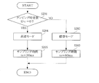
- FIG. 2 is a flowchart showing an example (Example 1) of the processing operation according to the automatic sampling condition changing function of the processing device of the differential pressure transmitter.
- FIG. 3 is a flowchart showing another example (Example 2) of the processing operation according to the sampling condition automatic changing function possessed by the processing device of the differential pressure transmitter.
- FIG. 4 is a flowchart showing another example (third embodiment) of the processing operation in accordance with the sampling condition automatic changing function possessed by the processing device of the differential pressure transmitter.
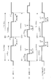
- FIG. 5 is a time chart for explaining the sampling operation in the standard mode and the high-speed mode in the first embodiment.
- FIG. 1 is a block diagram showing a main part of one embodiment of a differential pressure transmitter according to the present invention.
- FIG. 2 is a flowchart showing an example (Example 1) of the processing operation according to the automatic sampling condition changing function of the processing device of the differential
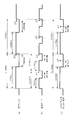
- FIG. 6 is a time chart for explaining a sampling operation in the standard mode and in the high speed mode in the second embodiment.
- FIG. 7 is a time chart for explaining the sampling operation in the standard mode and the high speed mode in the third embodiment.
- FIG. 8 is a diagram illustrating an example in which a display unit that displays a damping time constant and a sampling condition (sampling period, sampling time) used in the processing apparatus as setting conditions is provided.
- FIG. 9 is a functional block diagram in the processing device of the differential pressure transmitter.
- FIG. 10 is a time chart for explaining a sampling operation in a conventional differential pressure transmitter.
- FIG. 1 is a block diagram showing a main part of one embodiment of a differential pressure transmitter according to the present invention.
- 1 is a differential pressure sensor
- 2 is an A / D converter
- 3 is a processing unit (MPU)
- 4 is a D / A converter
- 5 is a setting of a damping time constant D ⁇ used in the processing device 3.
- a damping time constant setting changing unit (damping time constant setting changing means) that can be changed in accordance with an operation from a user.
- the differential pressure sensor 1 detects the pressure difference of the fluid and sends an electrical signal (analog value) corresponding to this pressure difference to the A / D converter 2.
- the A / D converter 2 operates constantly upon receiving the supply voltage Vcc, and converts an electrical signal corresponding to the pressure difference from the differential pressure sensor 1 into a digital value.
- the processing device 3 is realized by hardware including a processor and a storage device, and a program that realizes various functions as the processing device in cooperation with these hardware, and automatically changes sampling conditions as a function unique to the present embodiment. It has a function.
- a specific example of the sampling condition automatic changing function of the processing device 3 will be described with reference to the flowcharts shown in FIGS.
- Example 1 Example of automatically changing sampling cycle
- the processing device 3 shifts the sample mode from the standard mode to the high speed mode.
- the differential pressure measurement value ⁇ P is determined by performing various arithmetic processes such as square root extraction, and the differential pressure measurement value ⁇ P is output via the D / A converter 4 (see FIG. 5B). . In this calculation process, the processing device 3 does not execute a damping calculation.
- the processing device 3 shifts the sample mode from the standard mode to the high speed mode.
- the differential pressure measurement value ⁇ P is determined by performing various arithmetic processes such as square root extraction, and the differential pressure measurement value ⁇ P is output via the D / A converter 4 (see FIG. 6B). . In this calculation process, the processing device 3 does not execute a damping calculation.
- Example 3 Example of automatically changing sampling period and sampling time
- the processing device 3 shifts the sample mode from the standard mode to the high speed mode.
- the differential pressure measurement value ⁇ P is obtained by performing various arithmetic processes such as square root extraction, and the differential pressure measurement value ⁇ P is output via the D / A converter 4 (see FIG. 7B). . In this calculation process, the processing device 3 does not execute a damping calculation.
- the measurement value ⁇ P of the differential pressure can be obtained in a short cycle, and the measurement value ⁇ P of the differential pressure can be obtained in a short time after the start of the sampling cycle Ts to meet the demand for high-speed response. Will be able to.
- both the sampling time ts and the sampling cycle Ts are shortened, and the timing at which the differential pressure measurement value ⁇ P is obtained is accelerated, so that higher speed can be realized as compared with the standard mode.
- the sampling period Ts and the sampling time ts are automatically changed based on the damping time constant D ⁇ , so that the user is not aware of the sampling period or the sampling time, and can operate at high speed. Responsiveness can be realized. Moreover, since a single differential pressure transmitter can be used for various applications, it can greatly contribute to the reduction of spare parts for customers.
- the damping time constant D ⁇ is used to perform the damping calculation, while the sampling period Ts is automatically changed from 100 ms to 50 ms, or the sampling time ts is changed from 60 ms to 30 ms. It may be changed automatically to meet the demand for high-speed response.
- the sampling period Ts in the standard mode is set to 100 ms
- the sampling period Ts in the high speed mode is set to 50 ms
- the sampling in the high speed mode is performed.
- the time ts is set to 30 ms, it goes without saying that the sampling period Ts and the sampling time ts in the standard mode and the high-speed mode are not limited to these values.
- the sampling mode Ts and the sampling time ts may be changed according to the damping time constant D ⁇ to change the sampling mode Ts and increase the sampling mode.
- D ⁇ High-speed mode (for applications in which differential pressure transmitter response is particularly important), (2) Standard mode (for applications where external noise (for example, commercial noise) should be removed while maintaining a certain level of response ), (3) High stability mode (low speed mode: For applications where the stability of the output of the differential pressure transmitter is emphasized and the fluctuation of the process input is suppressed in addition to the external noise of the standard mode)
- the A / D filter constant resistance, capacitor
- the display unit (setting condition display means) 6 is provided as shown in FIG. 8, and the damping time constant D ⁇ used in the processing device 3 and the sampling conditions (sampling period Ts, sampling time ts). ) May be displayed on the display unit 6 as a setting condition.
- the current setting conditions can be known, and can be used as a reference when changing the damping time constant D ⁇ or the sampling conditions.
- the damping time constant D ⁇ is used as a parameter for determining the speed of calculation processing when obtaining the differential pressure measurement value, and the sampling period Ts and the sampling time ts are based on the damping time constant D ⁇ .
- the parameter that determines the speed of the calculation process when obtaining the differential pressure measurement value is not limited to the damping time constant D ⁇ .
- the degree of the correction calculation polynomial used in the calculation process for obtaining the measured value of the differential pressure is used as a parameter, and the sampling period Ts and the sampling time ts are automatically changed based on the order of the polynomial. Good.
- FIG. 9 shows a functional block diagram in the processing device 3 of the differential pressure transmitter 100 described above.
- the processing device 3 includes a sampling unit (sampling unit) 3A, a differential pressure measurement value calculation unit (differential pressure measurement value calculation unit) 3B, and a sampling condition automatic change unit (sampling condition automatic change unit). 3C.
- the sampling unit 3A samples an electrical signal corresponding to the fluid pressure difference detected by the differential pressure sensor 1 for each sampling period Ts during the sampling time ts.
- the differential pressure measurement value calculation unit 3B performs a calculation process including at least a damping calculation on the electrical signal sampled by the sampling unit 3A to obtain a measurement value ⁇ P of the differential pressure.
- the differential pressure transmitter of the present invention can be used in various fields such as fuel control for gas turbine power generation as a device for detecting and transmitting a pressure difference of a fluid.
Landscapes
- Physics & Mathematics (AREA)
- General Physics & Mathematics (AREA)
- Measuring Fluid Pressure (AREA)
Abstract
Description
処理装置3は、定期的に、現在設定されているダンピング時定数Dτをチェックする(図2:ステップS101)。ここで、ダンピング時定数DτがDτ≠0であれば(ステップS101のNO)、サンプルモードを標準モードとして(ステップS102)、サンプリング周期TsをTs=100msとする(ステップS103)。
処理装置3は、ダンピング時定数DτがDτ≠0で、標準モードとされている場合、A/D変換器2でデジタル値に変換された電気信号をサンプリング周期Ts=100ms毎にサンプリング時間ts=30msのあいだサンプリングし、このサンプリングした電気信号にリニアライズ演算,開平演算などの様々な演算処理を施して差圧の計測値ΔPを求め、この求めた差圧の計測値ΔPをD/A変換器4を介して出力する(図5(a)参照)。この演算処理において、処理装置3は、ダンピング時定数Dτを使用して、ダンピング演算を実行する。
処理装置3は、ダンピング時定数設定変更部5からのユーザの操作によって、ダンピング時定数DτがDτ=0に変更された場合、サンプルモードを標準モードから高速モードに移行する。この場合、処理装置3は、A/D変換器2でデジタル値に変換された電気信号をサンプリング周期Ts=50ms毎にサンプリング時間ts=30msのあいだサンプリングし、このサンプリングした電気信号にリニアライズ演算,開平演算などの様々な演算処理を施して差圧の計測値ΔPを求め、この求めた差圧の計測値ΔPをD/A変換器4を介して出力する(図5(b)参照)。この演算処理において、処理装置3は、ダンピング演算を実行しない。
処理装置3は、定期的に、現在設定されているダンピング時定数Dτをチェックする(図3:ステップS201)。ここで、ダンピング時定数DτがDτ≠0であれば(ステップS201のNO)、サンプルモードを標準モードとして(ステップS202)、サンプリング時間tsをts=60msとする(ステップS203)。
処理装置3は、ダンピング時定数DτがDτ≠0で、標準モードとされている場合、A/D変換器2でデジタル値に変換された電気信号をサンプリング周期Ts=100ms毎にサンプリング時間ts=60msのあいだサンプリングし、このサンプリングした電気信号にリニアライズ演算,開平演算などの様々な演算処理を施して差圧の計測値ΔPを求め、この求めた差圧の計測値ΔPをD/A変換器4を介して出力する(図6(a)参照)。この演算処理において、処理装置3は、ダンピング時定数Dτを使用して、ダンピング演算を実行する。
処理装置3は、ダンピング時定数設定変更部5からのユーザの操作によって、ダンピング時定数DτがDτ=0に変更された場合、サンプルモードを標準モードから高速モードに移行する。この場合、処理装置3は、A/D変換器2でデジタル値に変換された電気信号をサンプリング周期Ts=100ms毎にサンプリング時間ts=30msのあいだサンプリングし、このサンプリングした電気信号にリニアライズ演算,開平演算などの様々な演算処理を施して差圧の計測値ΔPを求め、この求めた差圧の計測値ΔPをD/A変換器4を介して出力する(図6(b)参照)。この演算処理において、処理装置3は、ダンピング演算を実行しない。
処理装置3は、定期的に、現在設定されているダンピング時定数Dτをチェックする(図4:ステップS301)。ここで、ダンピング時定数DτがDτ≠0であれば(ステップS301のNO)、サンプルモードを標準モードとして(ステップS302)、サンプリング周期TsをTs=100msとし(ステップS303)、サンプリング時間tsをts=60msとする(ステップS304)。
処理装置3は、ダンピング時定数DτがDτ≠0で、標準モードとされている場合、A/D変換器2でデジタル値に変換された電気信号をサンプリング周期Ts=100ms毎にサンプリング時間ts=60msのあいだサンプリングし、このサンプリングした電気信号にリニアライズ演算,開平演算などの様々な演算処理を施して差圧の計測値ΔPを求め、この求めた差圧の計測値ΔPをD/A変換器4を介して出力する(図7(a)参照)。この演算処理において、処理装置3は、ダンピング時定数Dτを使用して、ダンピング演算を実行する。
処理装置3は、ダンピング時定数設定変更部5からのユーザの操作によって、ダンピング時定数DτがDτ=0に変更された場合、サンプルモードを標準モードから高速モードに移行する。この場合、処理装置3は、A/D変換器2でデジタル値に変換された電気信号をサンプリング周期Ts=50ms毎にサンプリング時間ts=30msのあいだサンプリングし、このサンプリングした電気信号にリニアライズ演算,開平演算などの様々な演算処理を施して差圧の計測値ΔPを求め、この求めた差圧の計測値ΔPをD/A変換器4を介して出力する(図7(b)参照)。この演算処理において、処理装置3は、ダンピング演算を実行しない。
Claims (3)
- 流体の圧力差を検出する差圧センサと、
この差圧センサが検出する流体の圧力差に応じた電気信号を所定のサンプリング周期毎に所定のサンプリング時間のあいだサンプリングするサンプリング手段と、
このサンプリング手段によってサンプリングされた電気信号に少なくとも1次遅れ演算を含む演算処理を施して差圧の計測値を求める差圧計測値演算手段と、
前記サンプリング周期および前記サンプリング時間の少なくとも一方をサンプリング条件とし、前記演算処理のスピードを決定するパラメータに基づいて、前記演算処理のスピードが速くなる場合には短くなるように前記サンプリング条件を自動的に変更するサンプリング条件自動変更手段と
を備えることを特徴とする差圧発信器。 - 請求項1に記載された差圧発信器において、
前記演算処理のスピードを決定するパラメータは、
前記1次遅れ演算に際して用いられるダンピング時定数とされ、
前記ダンピング時定数の設定変更を可能とするダンピング時定数設定変更手段を備える
ことを特徴とする差圧発信器。 - 請求項2に記載された差圧発信器において、
前記ダンピング時定数および前記サンプリング条件の少なくとも一方を設定条件として表示する設定条件表示手段
を備えることを特徴とする差圧発信器。
Priority Applications (3)
| Application Number | Priority Date | Filing Date | Title |
|---|---|---|---|
| US12/865,450 US8326550B2 (en) | 2008-01-31 | 2009-01-14 | Differential pressure transmitter |
| CN2009801033372A CN101925937B (zh) | 2008-01-31 | 2009-01-14 | 差压变送器 |
| EP09706698.9A EP2239716B1 (en) | 2008-01-31 | 2009-01-14 | Differential pressure transmitter |
Applications Claiming Priority (2)
| Application Number | Priority Date | Filing Date | Title |
|---|---|---|---|
| JP2008020718A JP5330703B2 (ja) | 2008-01-31 | 2008-01-31 | 差圧発信器 |
| JP2008-020718 | 2008-01-31 |
Publications (1)
| Publication Number | Publication Date |
|---|---|
| WO2009096224A1 true WO2009096224A1 (ja) | 2009-08-06 |
Family
ID=40912577
Family Applications (1)
| Application Number | Title | Priority Date | Filing Date |
|---|---|---|---|
| PCT/JP2009/050367 Ceased WO2009096224A1 (ja) | 2008-01-31 | 2009-01-14 | 差圧発信器 |
Country Status (6)
| Country | Link |
|---|---|
| US (1) | US8326550B2 (ja) |
| EP (1) | EP2239716B1 (ja) |
| JP (1) | JP5330703B2 (ja) |
| KR (1) | KR101066509B1 (ja) |
| CN (1) | CN101925937B (ja) |
| WO (1) | WO2009096224A1 (ja) |
Families Citing this family (5)
| Publication number | Priority date | Publication date | Assignee | Title |
|---|---|---|---|---|
| CN103299350B (zh) * | 2011-02-04 | 2015-12-23 | 富士电机株式会社 | 电池式燃气报警器、其控制装置 |
| CN102331351B (zh) * | 2011-06-14 | 2013-01-02 | 山东电力研究院 | 试验专用差压变送器的连接方法 |
| US9136886B2 (en) | 2013-03-11 | 2015-09-15 | Rosemount Inc. | Digitally compensated process transmitter with minimal dead time |
| JP6197726B2 (ja) * | 2014-03-28 | 2017-09-20 | 横河電機株式会社 | フィールド機器の調整方法、フィールド機器の調整装置、及びフィールド機器 |
| JP6507761B2 (ja) * | 2015-03-23 | 2019-05-08 | 横河電機株式会社 | 差圧測定装置 |
Citations (7)
| Publication number | Priority date | Publication date | Assignee | Title |
|---|---|---|---|---|
| JPH0288921A (ja) | 1988-09-27 | 1990-03-29 | Yamatake Honeywell Co Ltd | 圧力補正形差圧発信器 |
| JPH03500717A (ja) * | 1987-10-16 | 1991-02-14 | ローズマウント インコ. | 応答速度の関数である可変分解能を備えたディジタル送信機 |
| JPH0421977U (ja) * | 1990-06-15 | 1992-02-24 | ||
| JPH04177599A (ja) * | 1990-11-09 | 1992-06-24 | Yokogawa Electric Corp | 信号伝送器 |
| US5909188A (en) * | 1997-02-24 | 1999-06-01 | Rosemont Inc. | Process control transmitter with adaptive analog-to-digital converter |
| JP2002048663A (ja) * | 2000-08-07 | 2002-02-15 | Seiko Instruments Inc | 携帯型圧力測定装置 |
| JP2003162790A (ja) * | 2001-11-28 | 2003-06-06 | Yamatake Corp | 2線式発信器における補正演算方法及び2線式発信器 |
Family Cites Families (10)
| Publication number | Priority date | Publication date | Assignee | Title |
|---|---|---|---|---|
| JPS6255705A (ja) * | 1985-09-03 | 1987-03-11 | Shimadzu Corp | プログラマブル制御装置 |
| JPS6266705A (ja) | 1985-09-18 | 1987-03-26 | Sharp Corp | コンバ−タ |
| JPH04195610A (ja) * | 1990-11-28 | 1992-07-15 | Shimadzu Corp | プロセス制御装置 |
| JPH05113379A (ja) * | 1991-10-22 | 1993-05-07 | Shimadzu Corp | 圧力・差圧伝送器 |
| JPH0619530A (ja) * | 1992-07-02 | 1994-01-28 | Hitachi Ltd | ディジタル調節計 |
| JP3223501B2 (ja) * | 1996-06-17 | 2001-10-29 | 横河電機株式会社 | 差圧測定装置 |
| DE10021644C2 (de) * | 2000-05-04 | 2002-08-01 | Bosch Gmbh Robert | Betriebszustandabhängiges Umschalten eines Abtastverfahrens eines Drucksensors |
| JP2003083830A (ja) * | 2001-09-14 | 2003-03-19 | Yokogawa Electric Corp | 差圧伝送器の時定数算出方法及び差圧伝送器 |
| JP4366652B2 (ja) * | 2004-04-23 | 2009-11-18 | 横河電機株式会社 | 伝送器及びその二重化方法 |
| US7770459B2 (en) * | 2007-07-20 | 2010-08-10 | Rosemount Inc. | Differential pressure diagnostic for process fluid pulsations |
-
2008
- 2008-01-31 JP JP2008020718A patent/JP5330703B2/ja active Active
-
2009
- 2009-01-14 WO PCT/JP2009/050367 patent/WO2009096224A1/ja not_active Ceased
- 2009-01-14 EP EP09706698.9A patent/EP2239716B1/en active Active
- 2009-01-14 KR KR1020107014587A patent/KR101066509B1/ko active Active
- 2009-01-14 US US12/865,450 patent/US8326550B2/en active Active
- 2009-01-14 CN CN2009801033372A patent/CN101925937B/zh active Active
Patent Citations (7)
| Publication number | Priority date | Publication date | Assignee | Title |
|---|---|---|---|---|
| JPH03500717A (ja) * | 1987-10-16 | 1991-02-14 | ローズマウント インコ. | 応答速度の関数である可変分解能を備えたディジタル送信機 |
| JPH0288921A (ja) | 1988-09-27 | 1990-03-29 | Yamatake Honeywell Co Ltd | 圧力補正形差圧発信器 |
| JPH0421977U (ja) * | 1990-06-15 | 1992-02-24 | ||
| JPH04177599A (ja) * | 1990-11-09 | 1992-06-24 | Yokogawa Electric Corp | 信号伝送器 |
| US5909188A (en) * | 1997-02-24 | 1999-06-01 | Rosemont Inc. | Process control transmitter with adaptive analog-to-digital converter |
| JP2002048663A (ja) * | 2000-08-07 | 2002-02-15 | Seiko Instruments Inc | 携帯型圧力測定装置 |
| JP2003162790A (ja) * | 2001-11-28 | 2003-06-06 | Yamatake Corp | 2線式発信器における補正演算方法及び2線式発信器 |
Non-Patent Citations (1)
| Title |
|---|
| See also references of EP2239716A4 * |
Also Published As
| Publication number | Publication date |
|---|---|
| EP2239716B1 (en) | 2017-11-15 |
| KR20100094549A (ko) | 2010-08-26 |
| JP5330703B2 (ja) | 2013-10-30 |
| US20110004424A1 (en) | 2011-01-06 |
| CN101925937B (zh) | 2012-11-21 |
| JP2009180643A (ja) | 2009-08-13 |
| US8326550B2 (en) | 2012-12-04 |
| EP2239716A4 (en) | 2014-06-18 |
| EP2239716A1 (en) | 2010-10-13 |
| KR101066509B1 (ko) | 2011-09-21 |
| CN101925937A (zh) | 2010-12-22 |
Similar Documents
| Publication | Publication Date | Title |
|---|---|---|
| TWI535304B (zh) | 揚聲器的磁力強度參數的偵測裝置及方法 | |
| JP5330703B2 (ja) | 差圧発信器 | |
| JP5798194B2 (ja) | 隔膜型圧力計 | |
| KR102568070B1 (ko) | 자동차 압력 센서에서의 비선형성 에러의 감소 | |
| WO2014196188A1 (ja) | 物理量センサの調整方法および物理量センサ | |
| CN101925936B (zh) | 检测设备 | |
| JP2016514838A (ja) | 振動センサ及び方法 | |
| WO2017072897A1 (ja) | 加速度センサシステム、及び自己診断方法 | |
| US9823149B2 (en) | Slew rate detection circuit | |
| JP2015180854A (ja) | 物理量検出装置 | |
| JP5253110B2 (ja) | 計測機器 | |
| WO2022198984A1 (zh) | 传感器的控制方法、装置、终端设备及存储介质 | |
| US20220390268A1 (en) | Method for Operating a Flowmeter and Flowmeter | |
| JP2017517944A (ja) | マイクロフォンアセンブリおよびマイクロフォンアセンブリの温度依存性を低減する方法 | |
| US9880063B2 (en) | Pressure sensor stabilization | |
| WO2022145273A1 (ja) | 液体状態検出センサ | |
| CN105987787A (zh) | 修正装置、修正方法、程序以及静电电容式压力传感器 | |
| JP5146861B1 (ja) | 測定手段と音響効果調整手段 | |
| KR102178794B1 (ko) | 온도센서와 정전용량센서가 결합된 지능형 복합 센서 장치 | |
| CN108318178B (zh) | 压力测量器 | |
| JP2018132433A (ja) | 圧力変化測定装置、高度測定装置、及び圧力変化測定方法 | |
| JP2018159641A (ja) | 電圧供給装置 | |
| JP2009053077A (ja) | 荷重測定装置及びその誤差補正方法 | |
| JP2019208245A (ja) | マイクロフォンアセンブリおよびマイクロフォンアセンブリの温度依存性を低減する方法 | |
| JP2012088195A (ja) | 圧力センサ |
Legal Events
| Date | Code | Title | Description |
|---|---|---|---|
| WWE | Wipo information: entry into national phase |
Ref document number: 200980103337.2 Country of ref document: CN |
|
| 121 | Ep: the epo has been informed by wipo that ep was designated in this application |
Ref document number: 09706698 Country of ref document: EP Kind code of ref document: A1 |
|
| ENP | Entry into the national phase |
Ref document number: 20107014587 Country of ref document: KR Kind code of ref document: A |
|
| REEP | Request for entry into the european phase |
Ref document number: 2009706698 Country of ref document: EP |
|
| WWE | Wipo information: entry into national phase |
Ref document number: 2009706698 Country of ref document: EP |
|
| WWE | Wipo information: entry into national phase |
Ref document number: 12865450 Country of ref document: US |
|
| NENP | Non-entry into the national phase |
Ref country code: DE |