WO2009113128A1 - 複数マッハツェンダー干渉計を有する光変調器の特性評価方法 - Google Patents
複数マッハツェンダー干渉計を有する光変調器の特性評価方法 Download PDFInfo
- Publication number
- WO2009113128A1 WO2009113128A1 PCT/JP2008/000575 JP2008000575W WO2009113128A1 WO 2009113128 A1 WO2009113128 A1 WO 2009113128A1 JP 2008000575 W JP2008000575 W JP 2008000575W WO 2009113128 A1 WO2009113128 A1 WO 2009113128A1
- Authority
- WO
- WIPO (PCT)
- Prior art keywords
- interferometer
- arms
- output
- intensity
- bias voltage
- Prior art date
- Legal status (The legal status is an assumption and is not a legal conclusion. Google has not performed a legal analysis and makes no representation as to the accuracy of the status listed.)
- Ceased
Links
Images


Classifications
-
- G—PHYSICS
- G01—MEASURING; TESTING
- G01B—MEASURING LENGTH, THICKNESS OR SIMILAR LINEAR DIMENSIONS; MEASURING ANGLES; MEASURING AREAS; MEASURING IRREGULARITIES OF SURFACES OR CONTOURS
- G01B9/00—Measuring instruments characterised by the use of optical techniques
- G01B9/02—Interferometers
-
- G—PHYSICS
- G01—MEASURING; TESTING
- G01M—TESTING STATIC OR DYNAMIC BALANCE OF MACHINES OR STRUCTURES; TESTING OF STRUCTURES OR APPARATUS, NOT OTHERWISE PROVIDED FOR
- G01M11/00—Testing of optical apparatus; Testing structures by optical methods not otherwise provided for
-
- G—PHYSICS
- G02—OPTICS
- G02F—OPTICAL DEVICES OR ARRANGEMENTS FOR THE CONTROL OF LIGHT BY MODIFICATION OF THE OPTICAL PROPERTIES OF THE MEDIA OF THE ELEMENTS INVOLVED THEREIN; NON-LINEAR OPTICS; FREQUENCY-CHANGING OF LIGHT; OPTICAL LOGIC ELEMENTS; OPTICAL ANALOGUE/DIGITAL CONVERTERS
- G02F1/00—Devices or arrangements for the control of the intensity, colour, phase, polarisation or direction of light arriving from an independent light source, e.g. switching, gating or modulating; Non-linear optics
- G02F1/01—Devices or arrangements for the control of the intensity, colour, phase, polarisation or direction of light arriving from an independent light source, e.g. switching, gating or modulating; Non-linear optics for the control of the intensity, phase, polarisation or colour
- G02F1/21—Devices or arrangements for the control of the intensity, colour, phase, polarisation or direction of light arriving from an independent light source, e.g. switching, gating or modulating; Non-linear optics for the control of the intensity, phase, polarisation or colour by interference
- G02F1/225—Devices or arrangements for the control of the intensity, colour, phase, polarisation or direction of light arriving from an independent light source, e.g. switching, gating or modulating; Non-linear optics for the control of the intensity, phase, polarisation or colour by interference in an optical waveguide structure
- G02F1/2255—Devices or arrangements for the control of the intensity, colour, phase, polarisation or direction of light arriving from an independent light source, e.g. switching, gating or modulating; Non-linear optics for the control of the intensity, phase, polarisation or colour by interference in an optical waveguide structure controlled by a high-frequency electromagnetic component in an electric waveguide structure
-
- G—PHYSICS
- G02—OPTICS
- G02F—OPTICAL DEVICES OR ARRANGEMENTS FOR THE CONTROL OF LIGHT BY MODIFICATION OF THE OPTICAL PROPERTIES OF THE MEDIA OF THE ELEMENTS INVOLVED THEREIN; NON-LINEAR OPTICS; FREQUENCY-CHANGING OF LIGHT; OPTICAL LOGIC ELEMENTS; OPTICAL ANALOGUE/DIGITAL CONVERTERS
- G02F1/00—Devices or arrangements for the control of the intensity, colour, phase, polarisation or direction of light arriving from an independent light source, e.g. switching, gating or modulating; Non-linear optics
- G02F1/01—Devices or arrangements for the control of the intensity, colour, phase, polarisation or direction of light arriving from an independent light source, e.g. switching, gating or modulating; Non-linear optics for the control of the intensity, phase, polarisation or colour
- G02F1/21—Devices or arrangements for the control of the intensity, colour, phase, polarisation or direction of light arriving from an independent light source, e.g. switching, gating or modulating; Non-linear optics for the control of the intensity, phase, polarisation or colour by interference
- G02F1/212—Mach-Zehnder type
-
- G—PHYSICS
- G02—OPTICS
- G02F—OPTICAL DEVICES OR ARRANGEMENTS FOR THE CONTROL OF LIGHT BY MODIFICATION OF THE OPTICAL PROPERTIES OF THE MEDIA OF THE ELEMENTS INVOLVED THEREIN; NON-LINEAR OPTICS; FREQUENCY-CHANGING OF LIGHT; OPTICAL LOGIC ELEMENTS; OPTICAL ANALOGUE/DIGITAL CONVERTERS
- G02F2201/00—Constructional arrangements not provided for in groups G02F1/00 - G02F7/00
- G02F2201/18—Constructional arrangements not provided for in groups G02F1/00 - G02F7/00 parallel
-
- G—PHYSICS
- G02—OPTICS
- G02F—OPTICAL DEVICES OR ARRANGEMENTS FOR THE CONTROL OF LIGHT BY MODIFICATION OF THE OPTICAL PROPERTIES OF THE MEDIA OF THE ELEMENTS INVOLVED THEREIN; NON-LINEAR OPTICS; FREQUENCY-CHANGING OF LIGHT; OPTICAL LOGIC ELEMENTS; OPTICAL ANALOGUE/DIGITAL CONVERTERS
- G02F2203/00—Function characteristic
- G02F2203/25—Frequency chirping of an optical modulator; Arrangements or methods for the pre-set or tuning thereof
-
- G—PHYSICS
- G02—OPTICS
- G02F—OPTICAL DEVICES OR ARRANGEMENTS FOR THE CONTROL OF LIGHT BY MODIFICATION OF THE OPTICAL PROPERTIES OF THE MEDIA OF THE ELEMENTS INVOLVED THEREIN; NON-LINEAR OPTICS; FREQUENCY-CHANGING OF LIGHT; OPTICAL LOGIC ELEMENTS; OPTICAL ANALOGUE/DIGITAL CONVERTERS
- G02F2203/00—Function characteristic
- G02F2203/69—Arrangements or methods for testing or calibrating a device
Definitions
- the present invention relates to a method for evaluating characteristics of an optical modulator having a Mach-Zehnder interferometer (MZ interferometer). Specifically, the present invention relates to a method for evaluating characteristics of an optical modulator having a plurality of Mach-Zehnder interferometers.
- MZ interferometer Mach-Zehnder interferometer
- Optical modulators are used in optical information communication systems. Therefore, grasping the characteristics of the optical modulator is useful for obtaining an effective optical information communication system.
- Parameters defining the performance of the optical modulator include insertion loss, modulation index, half-wave voltage (V ⁇ ), optical band, ON / OFF extinction ratio, polarization extinction ratio, chirp parameter, and the like. Then, methods for evaluating the characteristics of optical modulators were studied, and several evaluation methods were reported.
- Japanese Patent No. 3538619 discloses an invention for measuring a power spectrum of an MZ type optical modulator and obtaining a modulation index using the measured power spectrum.
- Japanese Patent No. 386682 discloses an invention for obtaining a half-wave voltage and a chirp parameter of an optical modulator from a spectrum distribution of the MZ type optical modulator.
- the method for evaluating the characteristics of the optical modulator disclosed in the above two documents is an excellent evaluation method. However, a method for evaluating the characteristics of the optical modulator with higher accuracy is desired.
- An object of the present invention is to provide a method for accurately evaluating the characteristics of an optical modulator.
- Another object of the present invention is to provide a method for evaluating the characteristics of individual MZ interferometers in an optical modulator including a plurality of MZ interferometers.
- the present invention is basically based on the knowledge that if the characteristics of the MZ interferometer are evaluated using the zeroth-order component of the MZ interferometer, accurate evaluation cannot be performed.
- the zero-order component includes a signal derived from an MZ interferometer other than the MZ interferometer whose characteristics are evaluated. For this reason, the characteristics of the MZ interferometer cannot be accurately evaluated.
- the 0th order component having the highest strength is usually not used for evaluating the characteristics. By doing so, the characteristics of the MZ interferometer can be evaluated with high accuracy.
- the first aspect of the present invention relates to a method for evaluating the characteristics of an optical modulator including a Mach-Zehnder interferometer (MZ interferometer).
- the MZ interferometer includes a demultiplexing unit, two arms, a multiplexing unit, and an electrode.
- the two arms are connected to the branching unit.
- the multiplexing unit is connected to two arms.
- the electrode can apply a bias voltage to the two arms.
- the electrode can apply a modulation signal to the two arms.
- the method includes a step of applying a drive signal, a step of sweeping a bias voltage, a step of measuring output intensity, and a step of evaluating characteristics.
- the step of applying a drive signal is a step of applying a drive signal to the MZ interferometer.
- the step of sweeping the bias voltage is a step of sweeping the bias voltage applied to the MZ interferometer.
- the step of measuring the output intensity is a step of measuring the output intensity from the MZ interferometer while sweeping the bias voltage in the step of sweeping the bias voltage.
- the step of evaluating the characteristics is a step of evaluating the characteristics of the MZ interferometer using the intensities of components other than the zero-order component among the outputs from the MZ interferometer measured in the step of measuring the output intensity.
- the method according to the first aspect evaluates the characteristics of the MZ interferometer without using the zeroth order component included in the output light. Therefore, it is possible to effectively evaluate the characteristics of a certain MZ interferometer in an optical modulator including a plurality of MZ interferometers.
- a preferable pattern of the method according to the first aspect is that the MZ interferometer described above is the first MZ interferometer. Then, the optical modulator further includes a second MZ interferometer. The second MZ interferometer is a different MZ interferometer from the first MZ interferometer.
- the present invention can effectively evaluate the characteristics of a certain MZ interferometer in an optical modulator including a plurality of MZ interferometers.
- a preferred pattern of the method according to the first aspect relates to a method for evaluating a characteristic ( ⁇ ) related to an unbalance of light amplitude between two arms.
- the unbalance of light amplitude between the two arms is an important parameter that determines the characteristics of the MZ interferometer. Therefore, by obtaining ⁇ or a value related to ⁇ , the MZ interferometer can be adjusted appropriately.
- This pattern can be combined with any of the pattern methods described above.
- a preferred pattern of the method according to the first aspect relates to evaluating a characteristic relating to a chirp parameter and a characteristic relating to a modulation index.
- the chirp parameter ( ⁇ ) is an important parameter that determines the characteristics of the MZ interferometer. Therefore, by obtaining ⁇ or a value related to ⁇ , the MZ interferometer can be adjusted appropriately.
- the modulation index (A 1 and A 2 ) is also an important parameter. This pattern can be combined with any of the pattern methods described above.
- a preferred pattern of the method according to the first aspect is that the step of evaluating the characteristics shows the sideband intensities from the first component to the fourth component of the output from the MZ interferometer measured in the step of measuring the output intensity. It is what you want. Then, the characteristics of the MZ interferometer are evaluated based on the obtained sideband intensities from the first to fourth order components.
- the second aspect of the present invention relates to a method for evaluating the characteristics of an optical modulator including a Mach-Zehnder interferometer (MZ interferometer).
- the MZ interferometer includes a demultiplexing unit, two arms, a multiplexing unit, and an electrode.
- the two arms are connected to the branching unit.
- the multiplexing unit is connected to two arms.
- the electrode can apply a bias voltage to the two arms.
- the electrode can apply a modulation signal to the two arms.
- the method according to the second aspect includes a step of applying a drive signal, a step of adjusting a bias voltage, a step of measuring output intensity, and a step of evaluating characteristics.
- the step of applying the drive signal is a step of applying the drive signal to the MZ interferometer.
- the step of adjusting the bias voltage is a step of setting the phase difference of the bias voltage applied to the two arms of the MZ interferometer to ⁇ , or the phase difference of the bias voltage applied to the two arms of the MZ interferometer is set to 0. It is a process.
- the step of measuring the output intensity is a step of measuring the output intensity from the MZ measurement system in which the bias voltage is adjusted by the step of adjusting the bias voltage.
- the step of evaluating the characteristic is a step of evaluating the characteristic of the MZ interferometer using the intensity of the secondary sideband component of the output from the MZ interferometer measured in the step of measuring the output intensity.
- the method according to the second aspect evaluates the characteristics of the MZ interferometer without using the zeroth-order component included in the output light. Therefore, it is possible to effectively evaluate the characteristics of a certain MZ interferometer in an optical modulator including a plurality of MZ interferometers.
- a preferable pattern of the method according to the second aspect is that the MZ interferometer described above is a second MZ interferometer. Then, the optical modulator further includes a second MZ interferometer. The second MZ interferometer is a different MZ interferometer from the second MZ interferometer.
- the present invention can effectively evaluate the characteristics of a certain MZ interferometer in an optical modulator including a plurality of MZ interferometers.
- a preferred pattern of the method according to the second aspect relates to a method for evaluating a characteristic ( ⁇ ) related to an unbalance of light amplitude between two arms.
- the unbalance of light amplitude between the two arms is an important parameter that determines the characteristics of the MZ interferometer. Therefore, by obtaining ⁇ or a value related to ⁇ , the MZ interferometer can be adjusted appropriately.
- This pattern can be combined with any of the pattern methods described above.
- a preferred pattern of the method according to the second aspect relates to evaluating a characteristic relating to a chirp parameter and a characteristic relating to a modulation index.
- the chirp parameter ( ⁇ ) is an important parameter that determines the characteristics of the MZ interferometer. Therefore, by obtaining ⁇ or a value related to ⁇ , the MZ interferometer can be adjusted appropriately.
- the modulation index (A 1 and A 2 ) is also an important parameter. This pattern can be combined with any of the pattern methods described above.
- the bias voltage is adjusted so that the odd-order component of the output light from the MZ interferometer is maximized and the even-order component other than the zero-order is minimized. Accordingly, the phase difference between the bias voltages applied to the two arms of the MZ interferometer is set to ⁇ .
- the bias voltage may be adjusted more simply so that the primary component of the output light from the MZ interferometer is maximized. Alternatively, the bias voltage may be adjusted so that the secondary component of the output light from the MZ interferometer is minimized. By doing so, the phase difference of the bias voltage can be effectively controlled without being influenced by other MZ interferometers.
- the bias voltage is adjusted so that the odd-order component of the output light from the MZ interferometer is minimized and the even-order component other than the zero-order is maximized.
- the phase difference between the bias voltages applied to the two arms of the MZ interferometer is set to zero.
- the bias voltage may be adjusted so that the primary component of the output light from the MZ interferometer is minimized.
- the bias voltage may be adjusted so that the secondary component of the output light from the MZ interferometer is maximized. In this way, the phase difference between the bias voltages applied to the two arms of the MZ interferometer can be easily set to zero.
- the step of setting the phase difference of the bias voltage applied to the two arms of the MZ interferometer to ⁇ includes the step of applying a signal having a skew to the two arms.
- the skew is a phase difference between RF (Radio Frequency) signals (modulation signals) applied to the two arms.
- the skew (that is, the phase difference between the RF signals applied to the two arms) is swept.
- the output from the MZ interferometer is measured while sweeping the skew. Then, it is determined whether the measured output from the MZ interferometer maintains symmetry.
- the bias voltage phase difference is determined to be ⁇ .
- the phase difference of the bias voltage is not ⁇ .
- the step of setting the phase difference of the bias voltage applied to the two arms of the MZ interferometer to ⁇ includes the step of applying a signal having a skew to the two arms. Then, the output from the MZ interferometer when the skew is swept is measured. Then, it includes a step of determining whether the difference between the intensity of the primary component and the intensity of the ⁇ 1st order component within the measured output from the MZ interferometer is within a certain range. In other words, if the primary component and the ⁇ 1st order component maintain the same intensity even if the skew changes, the symmetry between the 1st order component and the ⁇ 1st order component is maintained. In this case, the bias point is bias null (or bias full). Therefore, according to this pattern, it can be confirmed that the bias null is accurate.
- the step of setting the phase difference of the bias voltage applied to the two arms of the MZ interferometer to ⁇ includes the step of applying a signal having a skew to the two arms. Then, the output from the MZ interferometer when the skew is swept is measured. Then, it includes a step of determining whether the difference between the intensity of the secondary component and the intensity of the ⁇ 2nd component in the output from the measured MZ interferometer is within a certain range. In other words, if the second component and the second component maintain the same intensity even if the skew changes, the symmetry of the second component and the second component is maintained. Therefore, according to this pattern, it can be confirmed that the bias null is accurate.
- the step of setting the phase difference between the bias voltages applied to the two arms of the MZ interferometer to zero includes the step of applying a signal having a skew to the two arms.
- the skew is a phase difference between RF (Radio Frequency) signals (modulation signals) applied to the two arms. Then, the skew (that is, the phase difference between the RF signals applied to the two arms) is swept. Then, the output from the MZ interferometer is measured while sweeping the skew. Then, it is determined whether the measured output from the MZ interferometer maintains symmetry.
- the step of setting the phase difference between the bias voltages applied to the two arms of the MZ interferometer to zero includes the step of applying a signal having a skew to the two arms. Then, the output from the MZ interferometer when the skew is swept is measured. Then, it includes a step of determining whether the difference between the intensity of the primary component and the intensity of the ⁇ 1st order component within the measured output from the MZ interferometer is within a certain range. In other words, if the primary component and the ⁇ 1st order component maintain the same intensity even if the skew changes, the symmetry between the 1st order component and the ⁇ 1st order component is maintained. Therefore, according to this pattern, it is possible to confirm that the bias is fully accurate.
- the step of setting the phase difference between the bias voltages applied to the two arms of the MZ interferometer to zero includes the step of applying a signal having a skew to the two arms. Then, the output from the MZ interferometer when the skew is swept is measured. Then, it includes a step of determining whether the difference between the intensity of the secondary component and the intensity of the ⁇ 2nd component in the output from the measured MZ interferometer is within a certain range. In other words, if the second component and the second component maintain the same intensity even if the skew changes, the symmetry of the second component and the second component is maintained. Therefore, according to this pattern, it is possible to confirm that the bias is fully accurate.
- the method according to the third aspect includes a step of adjusting the bias voltage, a step of measuring the output intensity, and a step of evaluating the characteristics.
- the step of adjusting the bias voltage is a step of setting the voltage so that the phase difference between the bias voltages applied to the two arms of the MZ interferometer is 0 and the voltage between which the phase difference is ⁇ . .
- the step of measuring the output intensity is a step of obtaining the intensity of the higher-order component contained in the output light from the MZ interferometer.
- the step of evaluating the characteristic is a step of evaluating the characteristic of the MZ interferometer using the ratio of the higher order components measured in the step of measuring the output intensity.
- the configuration of the first aspect or the second aspect described above can be used.
- a method for accurately evaluating the characteristics of an optical modulator can be provided.
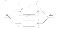
- FIG. 1 is a diagram illustrating an example of an optical modulator including a Mach-Zehnder interferometer.
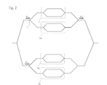
- FIG. 2 is a diagram illustrating an example of an optical modulator having a plurality of Mach-Zehnder interferometers.
- FIG. 3 is a diagram illustrating an example of an optical modulator including a plurality of Mach-Zehnder interferometers.
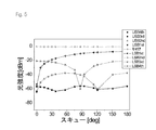
- FIG. 4 is a graph instead of a drawing showing the relationship between the output from the MZ interferometer and the skew in the case of bias null.
- FIG. 5 is a graph instead of a drawing showing the relationship between the output from the MZ interferometer and the skew when the bias is full.
- optical modulator 1 optical modulator 2 first Mach-Zehnder interferometer 3 second Mach-Zehnder interferometer 5 demultiplexing unit 6 first arm 7 second arm 8 multiplexing unit
- the first aspect of the present invention relates to a method for evaluating the characteristics of an optical modulator including a Mach-Zehnder interferometer (MZ interferometer).
- the MZ interferometer includes a demultiplexing unit, two arms, a multiplexing unit, and an electrode.
- the two arms are connected to the branching unit.
- the multiplexing unit is connected to two arms.
- the electrode can apply a bias voltage to the two arms.
- the electrode can apply a modulation signal to the two arms.
- FIG. 1 is a diagram illustrating an example of an optical modulator including a Mach-Zehnder interferometer.
- the optical modulator (1) includes a first Mach-Zehnder interferometer (2) and a second Mach-Zehnder interferometer (3).
- the first Mach-Zehnder interferometer (2) includes a demultiplexing unit (5), two arms (6, 7), a multiplexing unit (8), and an electrode (not shown).
- MZ interferometers and optical modulators including MZ interferometers are known.
- Reference numeral 6 indicates a first arm
- reference numeral 7 indicates a second arm. Normally, the Maha-Zehnder waveguide and electrodes are provided on the substrate.
- the substrate and each waveguide are not particularly limited as long as they can propagate light.
- a Ti diffusion lithium niobate waveguide may be formed on a lithium niobate (LN) substrate.
- a silicon dioxide (SiO 2 ) waveguide may be formed on a silicon (Si) substrate.
- an optical semiconductor waveguide in which an InGaAsP or GaAlAs waveguide is formed on an InP or GaAs substrate may be used.
- lithium niobate (LiNbO 3 : LN) cut out to achieve X-cut Z-axis propagation is preferable.
- An optical waveguide is formed on the surface of the X cut surface (YZ surface) of the substrate, and the guided light propagates along the Z axis (optical axis).
- a lithium niobate substrate other than the X cut, such as a Z cut, may be used.
- a triaxial or hexagonal uniaxial crystal having an electro-optic effect, or a material whose crystal point group is C 3V , C 3 , D 3 , C 3h , D 3h can be used. .
- These materials have a function of adjusting the refractive index so that the change in refractive index is different depending on the mode of propagating light when an electric field is applied.
- lithium tantalate LiTO 3 : LT
- ⁇ -BaB 2 O 4 abbreviation BBO
- LiIO 3 a specific example, in addition to lithium niobate, lithium tantalate (LiTO 3 : LT), ⁇ -BaB 2 O 4 (abbreviation BBO), LiIO 3 or the like can be used.
- LiTO 3 : LT lithium tantalate
- ⁇ -BaB 2 O 4 abbreviation BBO
- LiIO 3 LiIO 3
- a waveguide is formed on the X-cut surface
- a waveguide is formed on the Z-cut surface, it is preferable to provide two electrodes on both sides of the waveguide. It is preferable that positive and negative signals can be simultaneously applied to these
- FIG. 2 is a diagram showing an example of an optical modulator having a plurality of Mach-Zehnder interferometers.
- This optical modulator has two main Mach-Zehnder interferometers. Each main Mach-Zehnder interferometer has two sub Mach-Zehnder waveguides.
- the Mach-Zehnder interferometer to be evaluated is indicated by reference numeral 2.
- this optical modulator includes Mach-Zehnder interferometers (3a, 3b, 3c) other than those to be evaluated.
- the optical modulator shown in FIG. 2 functions as a quadrature amplitude modulation (QAM) signal generator. That is, the present invention can be effectively used to evaluate the characteristics of a Mach-Zehnder waveguide included in a quadrature amplitude modulation (QAM) signal generator.
- QAM quadrature amplitude modulation
- FIG. 3 is a diagram illustrating an example of an optical modulator including a plurality of Mach-Zehnder interferometers. This optical modulator is formed by arranging a plurality of modulators including Mach-Zehnder waveguides.
- the wave function of the input light to the MZ interferometer can be expressed by exp (i ⁇ 0 t).
- the phase of the optical signal propagating through both arms of the MZ interferometer can be expressed as follows.
- ⁇ 0 is the angular frequency of light
- a 1 and A 2 are parameters (modulation index) representing the modulation depth of each arm
- ⁇ m is the angular frequency of the modulation signal
- ⁇ 1 , ⁇ 2 Represents the phase of the modulation signal depending on the arm
- B 1 and B 2 represent the phases of both arms depending on the structure and state of the waveguide.
- the optical modulator has a plurality of MZ interferometers, unmodulated light due to them cannot be ignored.
- the unmodulated light derived from another MZ interferometer is Gexp (i ⁇ 0 t). Then, the output from the MZ interferometer can be expressed as follows.
- n represents the order
- ⁇ represents the extinction ratio related to the imbalance of the light amplitude between the two arms.
- J n is a first type Bessel function.
- ⁇ ′ is A ⁇ 0
- a 1 is A + ⁇ ′
- a 2 is ⁇ A + ⁇ ′.
- n be an integer of 1 or greater.
- the intensity of the sideband component has a property that depends on the bias voltage. In order to cancel this property, for example, the bias voltage is swept at an integral multiple of the half-wave voltage.
- S n can be expressed as follows.
- Jn ′ (A) of Jn is defined as follows.
- S n can be expressed as follows.
- R 1n can be expressed as follows.
- the above formula When evaluating the characteristics of the MZ interferometer using the ratio between the first-order sideband intensity and the second to fourth-order sideband intensity, the above formula may be used.
- the first aspect of the present invention includes a step of applying a drive signal, a step of sweeping a bias voltage, a step of measuring output intensity, and a step of evaluating characteristics.
- the step of applying a drive signal is a step of applying a drive signal to the MZ interferometer.
- a sine wave is an example of the drive signal.
- the drive frequency of the drive signal is 1 to 10 GHz. Since this step is the same as that for driving the MZ interferometer, it can be easily realized.
- This step may be automatically performed based on the control device. That is, the optical modulator includes, for example, a drive signal source and a control device. The control device reads the control program. Then, the control device issues a command to the drive signal source based on the read control program. The drive signal source receives a command from the control device. The drive signal source applies a drive signal to the electrodes of the MZ interferometer according to the control command. In this way, a drive signal can be applied to the MZ interferometer.
- the step of sweeping the bias voltage is a step of sweeping the bias voltage applied to the MZ interferometer.
- the optical modulator includes, for example, a bias power supply and a control device.
- the control device reads the control program.
- the control device issues a command to the bias power supply based on the read control program.
- the bias power supply receives a command from the control device.
- the bias power source sweeps the bias voltage to the electrode of the MZ interferometer according to the control command. In this way, the bias voltage applied to the two arms of the interferometer can be swept.
- the range of the voltage to be changed during the sweeping is made to coincide with an integral multiple of the half-wave voltage of the electrode to which the bias voltage is applied (the voltage necessary for turning on and off the interferometer).
- the sweeping method is the method of using the value measured in advance, the range of the sweep voltage while changing the center value of the sweep voltage, and the voltage at which the spectrum does not depend on the change of the center value. There is a way to search the range. The latter uses the property that the spectrum does not depend on the center value of the sweep only when the range of change of the sweep voltage matches an integral multiple of the half-wave voltage.
- the step of measuring the output intensity is a step of measuring the output intensity from the MZ interferometer while sweeping the bias voltage in the step of sweeping the bias voltage.
- the sideband intensity of the first to fourth components is raised.
- This optical modulator includes, for example, a photodetector. Then, the photodetector measures the output light from the MZ interferometer. The photodetector obtains intensity information of a predetermined peak from the detected spectrum of output light. Specifically, the sideband intensity of the quaternary component is extracted from the primary component.
- This step may be automatically performed based on the control device. That is, the control device includes a control program. Then, the control device stores the frequencies of the first to fourth components.
- the control device receives information about the output spectrum of the MZ interferometer from the photodetector. Then, the control device extracts the sideband intensity of the primary component to the sideband intensity of the quaternary component from the output spectrum by using information on the frequencies of the primary component to the quaternary component.
- the step of evaluating the characteristic is a step of evaluating the characteristic of the MZ interferometer by using the intensity of components other than the zero-order component among the outputs from the MZ interferometer measured in the step of measuring the output intensity.
- the nth-order sideband intensity can be expressed as follows.
- R 1n can be expressed as follows.
- the photodetector further includes a control device.
- the control device includes a program for solving simultaneous equations and a program for handling Bessel functions.
- S 1 to S 4 could be obtained. Therefore, using S 1 to S 4 , R 12 , R 13 , and R 14 can be easily obtained by using a table and a multiplier. Further, R 12 , R 13 , and R 14 can be easily obtained from S 1 to S 4 using software. Thereafter, A, ⁇ , and ⁇ ′ can be obtained by a program for solving simultaneous equations.
- the method according to the first aspect evaluates the characteristics of the MZ interferometer without using the zeroth order component included in the output light. Therefore, it is possible to effectively evaluate the characteristics of a certain MZ interferometer in an optical modulator including a plurality of MZ interferometers.
- a preferable pattern of the method according to the first aspect is that the MZ interferometer described above is the first MZ interferometer. Then, the optical modulator further includes a second MZ interferometer. The second MZ interferometer is a different MZ interferometer from the first MZ interferometer.
- the present invention can effectively evaluate the characteristics of a certain MZ interferometer in an optical modulator including a plurality of MZ interferometers.
- a preferred pattern of the method according to the first aspect relates to a method for evaluating a characteristic ( ⁇ ) related to an unbalance of light amplitude between two arms.
- the unbalance of light amplitude between the two arms is an important parameter that determines the characteristics of the MZ interferometer. Therefore, by obtaining ⁇ or a value related to ⁇ , the MZ interferometer can be adjusted appropriately.
- This pattern can be combined with any of the pattern methods described above.
- a preferred pattern of the method according to the first aspect relates to evaluating a characteristic relating to a chirp parameter and a characteristic relating to a modulation index.
- the chirp parameter ( ⁇ ) is an important parameter that determines the characteristics of the MZ interferometer. Therefore, by obtaining ⁇ or a value related to ⁇ , the MZ interferometer can be adjusted appropriately.
- the modulation index (A 1 and A 2 ) is also an important parameter. This pattern can be combined with any of the pattern methods described above.
- the second aspect of the present invention relates to a method for evaluating the characteristics of an optical modulator including a Mach-Zehnder interferometer (MZ interferometer).
- the MZ interferometer includes a demultiplexing unit, two arms, a multiplexing unit, and an electrode.
- the two arms are connected to the branching unit.
- the multiplexing unit is connected to two arms.
- the electrode can apply a bias voltage to the two arms.
- the electrode can apply a modulation signal to the two arms.
- S n can be expressed as follows.
- the nth-order sideband intensity can be approximately expressed as follows when ⁇ is small.
- the primary to tertiary sidebands when the bias is full can be expressed in the following table.
- the first to third sidebands in the case of bias null can be expressed in the following table.
- the extinction ratios ⁇ , ⁇ ′, and A can be obtained from the sideband intensities at the time of bias full and bias null. That is, A can be obtained from the secondary sideband when the bias is full.
- ⁇ can be changed. Thereby, ⁇ ′ can be obtained.
- ⁇ at the time of bias null can be obtained.
- the second aspect of the present invention includes a step of applying a drive signal, a step of adjusting a bias voltage, a step of measuring output intensity, and a step of evaluating characteristics.
- the step of applying a drive signal is a step of applying a drive signal to the MZ interferometer. This step is the same as the first side.
- the step of adjusting the bias voltage is a step of setting the phase difference of the bias voltage applied to the two arms of the MZ interferometer to ⁇ , or the phase difference of the bias voltage applied to the two arms of the MZ interferometer is set to 0. It is a process. This step can be easily achieved by adjusting the voltage applied to the bias electrode. This step may be automatically performed based on the control device. That is, the optical modulator includes, for example, a bias power supply and a control device. The control device reads the control program. Then, the control device issues a command to the bias power supply based on the read control program. The bias power supply receives a command from the control device. The bias power source applies a bias voltage to the electrodes of the MZ interferometer according to the control command. In this way, the phase difference between the bias voltages applied to the two arms of the Z interferometer can be set to 0 or ⁇ .
- the bias full state and the bias null state are controlled using the intensity of the 0th order component of the output light.
- the optical modulator includes an MZ interferometer other than the MZ interferometer to be evaluated
- noise derived from other MZ interferometers is generated in the zero-order component. Therefore, it is difficult to accurately distinguish the bias full state and the bias null state with the zero-order component. Therefore, in the present invention, it is preferable to discriminate between the bias full state and the null state using a high-order component.
- the even order second order, fourth order, sixth order, etc.
- the odd order including the first order first order, third order, fifth order, etc.
- the odd order including the first order is the largest, and the even order including the zero order (second order, fourth order, sixth order, etc.) is the smallest.
- the bias should be set so that That is, in order to set the phase difference between the bias voltages applied to the two arms of the MZ interferometer to ⁇ , the bias null state may be set. Therefore, the odd order including the first order (first order, third order, fifth order, etc.) is maximized, and the even order including the zero order (second order, fourth order, sixth order, etc.) is minimized. What is necessary is just to set a bias.
- control may be performed so that the primary component is maximized.
- control may be performed so that the secondary component is minimized.
- the preferred pattern of the method according to the first aspect is to adjust the bias voltage so that the odd-order component of the output light from the MZ interferometer is maximized and the even-order component other than the zero-order is minimized. is there. Accordingly, the phase difference between the bias voltages applied to the two arms of the MZ interferometer is set to ⁇ . This step can be achieved by adjusting the bias voltage while analyzing the spectrum detected by the photodetector.
- control unit may automatically analyze the spectrum detected by the photodetector and give a command to the bias power supply to change the bias voltage.
- a bias null state can be automatically obtained.
- the bias voltage may be adjusted more simply so that the primary component of the output light from the MZ interferometer is maximized.
- the bias voltage may be adjusted so that the secondary component of the output light from the MZ interferometer is minimized. By doing so, the phase difference of the bias voltage can be effectively controlled without being influenced by other MZ interferometers.
- the bias voltage is adjusted so that the odd-order component of the output light from the MZ interferometer is minimized and the even-order component other than the zero-order is maximized.
- the phase difference of the bias voltage applied to the two arms of the MZ interferometer can be made zero.
- the bias voltage may be adjusted so that the primary component of the output light from the MZ interferometer is minimized.
- the bias voltage may be adjusted so that the secondary component of the output light from the MZ interferometer is maximized. In this way, the phase difference between the bias voltages applied to the two arms of the MZ interferometer can be easily set to zero.
- the step of measuring the output intensity is a step of measuring the output intensity from the MZ measurement system whose bias voltage has been adjusted by the process of adjusting the bias voltage. This process is also basically the same as the first aspect.
- the step of evaluating the characteristic is a step of evaluating the characteristic of the MZ interferometer using the intensity of the secondary sideband component of the output from the MZ interferometer measured in the step of measuring the output intensity.
- the method according to the second aspect evaluates the characteristics of the MZ interferometer without using the zeroth-order component included in the output light. Therefore, it is possible to effectively evaluate the characteristics of a certain MZ interferometer in an optical modulator including a plurality of MZ interferometers.
- a preferable pattern of the method according to the second aspect is that the MZ interferometer described above is a second MZ interferometer. Then, the optical modulator further includes a second MZ interferometer. The second MZ interferometer is a different MZ interferometer from the second MZ interferometer.
- the present invention can effectively evaluate the characteristics of a certain MZ interferometer in an optical modulator including a plurality of MZ interferometers.
- a preferred pattern of the method according to the second aspect relates to a method for evaluating a characteristic ( ⁇ ) related to an unbalance of light amplitude between two arms.
- the unbalance of light amplitude between the two arms is an important parameter that determines the characteristics of the MZ interferometer. Therefore, by obtaining ⁇ or a value related to ⁇ , the MZ interferometer can be adjusted appropriately.
- This pattern can be combined with any of the pattern methods described above.
- a preferred pattern of the method according to the second aspect relates to evaluating a characteristic relating to a chirp parameter and a characteristic relating to a modulation index.
- the chirp parameter ( ⁇ ) is an important parameter that determines the characteristics of the MZ interferometer. Therefore, by obtaining ⁇ or a value related to ⁇ , the MZ interferometer can be adjusted appropriately.
- the modulation index (A 1 and A 2 ) is also an important parameter. This pattern can be combined with any of the pattern methods described above.
- the preferred pattern of the method according to the second aspect is that the RF signal is applied to the two arms of the MZ interferometer and the RF signal has a skew (phase difference) so that the bias null is accurately obtained. It is to confirm. If the bias null is not accurately set, the bias is adjusted. By doing so, the bias null can be accurately set, and the characteristics of the MZ interferometer can be accurately evaluated. This point will be described below.
- skew phase difference
- the optical spectrum changes. For this reason, adjustment is usually made so that the skew is as small as possible.
- each order component has periodicity (symmetry). That is, the n-order component has a zero point at a 2 ⁇ / n cycle. Thereby, the n-order component can be easily separated from the output spectrum. The reason why the output spectrum has periodicity is considered to be due to some reason.
- the intensity of the n-th order component is proportional to cos [ ⁇ n ( ⁇ + ⁇ ) + B ⁇ / 2]. For this reason, the n-order component is considered to have a zero point at a 2 ⁇ / n cycle.
- USB upper sideband
- LSB lower sideband
- FIG. 4 is a graph instead of a drawing showing the relationship between the output from the MZ interferometer and the skew in the case of bias null (null bias).
- FIG. 4 shows the output from the MZ interferometer in the case of DSB-SC modulation.
- the carrier component continues to be suppressed even if the skew changes.
- the skew reached 180 degrees, the light intensity as a whole decreased. This is considered to be because the optical phase is inverted between the two arms. That is, it is considered that the light intensity as a whole is weakened because the components whose phases are reversed interfere with each other and cancel each other.
- the primary component (and the ⁇ 1st order component) had a maximum when the skew was 0 degrees and a minimum when the skew was 180 degrees.
- the interval between the zero points was 360 degrees (2 ⁇ ).
- the intensities of the first-order component and the ⁇ 1st-order component are almost the same in each skew, and the symmetry between the first-order component and the ⁇ 1st-order component is maintained.
- the secondary component (and -2nd order component) was minimized when the skew was 0 degrees and minimized when the skew was 180 degrees.
- the interval between the zero points was 180 degrees (2 ⁇ / 2).
- the intensities of the secondary component and the ⁇ 2nd component are almost the same in each skew, and the symmetry between the secondary component and the ⁇ 2nd component is maintained.
- the third-order component ( ⁇ third-order component) was maximum when the skew was 0 degrees, and minimized when the skew was 60 degrees and 180 degrees.
- the interval between the zero points was 120 degrees (2 ⁇ / 3).
- the intensities of the third-order component and the third-order component were almost the same in each skew, and the symmetry between the third-order component and the third-order component was maintained.
- FIG. 5 is a graph instead of a drawing showing the relationship between the output from the MZ interferometer and the skew in the case of bias full (full bias).
- FIG. 5 shows the output from the MZ interferometer when the odd-order component is suppressed.
- FIG. 5 shows that the intensity of the carrier component does not change even if the skew changes.
- the intensity of the suppressed first-order component and ⁇ 1st-order component
- the primary component had a maximum when the skew was 0 degrees and a minimum when the skew was 180 degrees.
- the interval between the zero points was 360 degrees (2 ⁇ ).
- the intensities of the first-order component and the ⁇ 1st-order component are almost the same in each skew, and the symmetry between the first-order component and the ⁇ 1st-order component is maintained.
- the secondary component (and the ⁇ 2nd order component) was minimized when the skew was 0 degrees and minimized when the skew was 90 degrees.
- the interval between the zero points was 180 degrees (2 ⁇ / 2).
- the intensities of the secondary component and the ⁇ 2nd component are almost the same in each skew, and the symmetry between the secondary component and the ⁇ 2nd component is maintained.
- the third-order component ( ⁇ third-order component) was maximized when the skew was 0 degrees and minimized when the skew was 120 degrees.
- the interval between the zero points was 120 degrees (2 ⁇ / 3).
- the intensities of the third-order component and the third-order component were almost the same in each skew, and the symmetry between the third-order component and the third-order component was maintained.
- the bias null or the bias full when the difference between the USB intensity and the LSB intensity is within a certain range, it can be determined that the bias null or the bias full.
- a certain range may be set as appropriate. If this range is narrow, more accurate bias null or bias full can be achieved.
- the step of setting the phase difference of the bias voltage applied to the two arms of the MZ interferometer to ⁇ includes the step of applying a signal having a skew to the two arms.
- the skew is a phase difference between RF (Radio Frequency) signals (modulation signals) applied to the two arms.
- the RF signal source is connected to the control device.
- the RF signal source is connected to an electrode for applying a modulation signal to the two arms.
- the control unit issues a command to output an RF signal to the RF signal source. This command takes into account the phase difference between the RF signals applied to the two arms.
- the controller can sweep the skew (that is, the phase difference between the RF signals applied to the two arms) by sweeping the phase difference. Then, the output from the MZ interferometer is measured while sweeping the skew. Then, it is determined whether the measured output from the MZ interferometer maintains symmetry.
- the photodetector is connected to the control device. Therefore, the output spectrum detected by the photodetector is input to the control device.
- the control device separates each order component from the output spectrum. Then, it is determined whether the n-order component and the -n-order component have the same intensity. For example, a ratio between the intensity of the primary component and the intensity of the ⁇ 1st order component is obtained, and it is determined whether this ratio is 0.95 or more and 1.05 or less. This range may be adjusted as appropriate. Thus, it is determined whether the output from the MZ interferometer maintains symmetry.
- the step of setting the phase difference of the bias voltage applied to the two arms of the MZ interferometer to ⁇ includes the step of applying a signal having a skew to the two arms. Then, the output from the MZ interferometer when the skew is swept is measured. Then, it includes a step of determining whether the difference between the intensity of the primary component and the intensity of the ⁇ 1st order component within the measured output from the MZ interferometer is within a certain range. In other words, if the primary component and the ⁇ 1st order component maintain the same intensity even if the skew changes, the symmetry between the 1st order component and the ⁇ 1st order component is maintained. Therefore, according to this pattern, it can be confirmed that the bias null is accurate.
- the step of setting the phase difference of the bias voltage applied to the two arms of the MZ interferometer to ⁇ includes the step of applying a signal having a skew to the two arms. Then, the output from the MZ interferometer when the skew is swept is measured. Then, it includes a step of determining whether the difference between the intensity of the secondary component and the intensity of the ⁇ 2nd component in the output from the measured MZ interferometer is within a certain range. In other words, if the second component and the second component maintain the same intensity even if the skew changes, the symmetry of the second component and the second component is maintained. Therefore, according to this pattern, it can be confirmed that the bias null is accurate.
- a preferable pattern of the method according to the second aspect is to obtain a bias null state accurately using skew.
- the bias null state can be accurately achieved in the same manner as the principle described in the first aspect.
- the step of setting the phase difference between the bias voltages applied to the two arms of the MZ interferometer to 0 includes the step of applying a signal having a skew to the two arms.
- the skew is a phase difference between RF (Radio Frequency) signals (modulation signals) applied to the two arms.
- the skew that is, the phase difference between the RF signals applied to the two arms
- the output from the MZ interferometer is measured while sweeping the skew.
- the step of setting the phase difference between the bias voltages applied to the two arms of the MZ interferometer to zero includes the step of applying a signal having a skew to the two arms. Then, the output from the MZ interferometer when the skew is swept is measured. Then, it includes a step of determining whether the difference between the intensity of the primary component and the intensity of the ⁇ 1st order component within the measured output from the MZ interferometer is within a certain range. In other words, if the primary component and the ⁇ 1st order component maintain the same intensity even if the skew changes, the symmetry between the 1st order component and the ⁇ 1st order component is maintained. Therefore, according to this pattern, it is possible to confirm that the bias is fully accurate.
- the step of setting the phase difference between the bias voltages applied to the two arms of the MZ interferometer to zero includes the step of applying a signal having a skew to the two arms. Then, the output from the MZ interferometer when the skew is swept is measured. Then, it includes a step of determining whether the difference between the intensity of the secondary component and the intensity of the ⁇ 2nd component in the output from the measured MZ interferometer is within a certain range. In other words, if the second component and the second component maintain the same intensity even if the skew changes, the symmetry of the second component and the second component is maintained. Therefore, according to this pattern, it is possible to confirm that the bias is fully accurate.
- ⁇ is not variable
- the characteristics of the Mach-Zehnder interferometer may be evaluated as follows, for example. Measure the output intensity for bias full and null. In this case, each intensity (relative value) can be expressed by the formula already shown. Therefore, using this data, multiple simultaneous nonlinear equations can be established. A variable can be obtained by establishing simultaneous equations more than the variable. Therefore, A, ⁇ , and ⁇ can be obtained by creating three or more simultaneous equations and solving them. As described above, when a plurality of MZ interferometers are provided, noise derived from MZ interferometers other than the measurement target is generated as the zero-order component.
- Nonlinear simultaneous equations may have multiple solutions. In this case, a solution can be easily obtained by establishing four or more simultaneous equations.
- the method according to the third aspect includes a step of adjusting the bias voltage, a step of measuring the output intensity, and a step of evaluating the characteristics.
- the step of adjusting the bias voltage is a step of setting the voltage so that the phase difference between the bias voltages applied to the two arms of the MZ interferometer is 0 and the voltage between which the phase difference is ⁇ . . What is necessary is just to utilize what was demonstrated previously suitably as the method of calculating
- the optical modulator may be one that can be automatically controlled using a control device.
- the control device stores a voltage with a phase difference of 0 and a voltage with a phase difference of ⁇ , calculates an average of them, and issues a command to the bias power supply so as to output a bias voltage of the average value.
- the step of measuring the output intensity is a step of obtaining the intensity of the higher-order component contained in the output light from the MZ interferometer.
- the step of evaluating the characteristic is a step of evaluating the characteristic of the MZ interferometer using the ratio of the higher order components measured in the step of measuring the output intensity.
- the present invention can also evaluate the characteristics of the MZ interferometer using an intermediate state between bias full and bias null. In this case, the intensity of each component is the average of the equations shown above.
- a system having such an optical modulator includes an optical modulator, a photodetector, a power source, and a control device.
- the power supply applies a modulation signal and a bias voltage to the optical modulator.
- the photodetector can measure the output of the optical modulator or the output from the MZ interferometer included in the optical modulator.
- the control device is connected to the photodetector and can receive spectral information detected by the photodetector. In addition, the control device controls the operation of the power supply based on the received spectrum information.
- the phase difference between the RF signals between the arms may be evaluated as follows. That is, the characteristics may be evaluated using the intermediate state between bias full and bias null described above. That is, when the phase difference between the RF signals between the arms cannot be ignored, the intensity between the + n-order component and the -n-order component is unbalanced at a bias voltage between bias full and bias null.
- the phase difference of the RF signal between the arms can be evaluated using the ratio between the + n-order component and the -n-order component. That is, if this ratio takes a value within a certain range close to 1, the phase difference of the inter-arm RF signal can be ignored.
- the phase difference between the RF signals between the arms can be evaluated by obtaining an intermediate state between bias full and bias null and obtaining the ratio of the + n order component and the ⁇ n order component.
- the present invention can be suitably used in the field of optical information communication.
Landscapes
- Physics & Mathematics (AREA)
- General Physics & Mathematics (AREA)
- Nonlinear Science (AREA)
- Chemical & Material Sciences (AREA)
- Analytical Chemistry (AREA)
- Electromagnetism (AREA)
- Optics & Photonics (AREA)
- Optical Modulation, Optical Deflection, Nonlinear Optics, Optical Demodulation, Optical Logic Elements (AREA)
- Testing Of Optical Devices Or Fibers (AREA)
Priority Applications (6)
| Application Number | Priority Date | Filing Date | Title |
|---|---|---|---|
| PCT/JP2008/000575 WO2009113128A1 (ja) | 2008-03-13 | 2008-03-13 | 複数マッハツェンダー干渉計を有する光変調器の特性評価方法 |
| EP08720461.6A EP2261628B1 (de) | 2008-03-13 | 2008-03-13 | Verfahren der evaluierung von charakteristiken eines mach-zehnder-interferometers innerhalb eines optischen modulators |
| JP2010502645A JP5035411B2 (ja) | 2008-03-13 | 2008-03-13 | 複数マッハツェンダー干渉計を有する光変調器の特性評価方法 |
| US12/921,833 US8446591B2 (en) | 2008-03-13 | 2008-03-13 | Method for evaluating characteristics of optical modulator having Mach-Zehnder interferometers |
| EP10187187.9A EP2309323B1 (de) | 2008-03-13 | 2008-03-13 | Verfahren zur bestimmung von eigenschaften eines optischen modulators, der mehrere mach-zehnder'sche interferometer umfasst |
| US13/845,393 US8693005B2 (en) | 2008-03-13 | 2013-03-18 | Method for evaluating characteristics of optical modulator having Mach-Zehnder interferometers |
Applications Claiming Priority (1)
| Application Number | Priority Date | Filing Date | Title |
|---|---|---|---|
| PCT/JP2008/000575 WO2009113128A1 (ja) | 2008-03-13 | 2008-03-13 | 複数マッハツェンダー干渉計を有する光変調器の特性評価方法 |
Related Child Applications (2)
| Application Number | Title | Priority Date | Filing Date |
|---|---|---|---|
| US12/921,833 A-371-Of-International US8446591B2 (en) | 2008-03-13 | 2008-03-13 | Method for evaluating characteristics of optical modulator having Mach-Zehnder interferometers |
| US13/845,393 Continuation US8693005B2 (en) | 2008-03-13 | 2013-03-18 | Method for evaluating characteristics of optical modulator having Mach-Zehnder interferometers |
Publications (1)
| Publication Number | Publication Date |
|---|---|
| WO2009113128A1 true WO2009113128A1 (ja) | 2009-09-17 |
Family
ID=41064813
Family Applications (1)
| Application Number | Title | Priority Date | Filing Date |
|---|---|---|---|
| PCT/JP2008/000575 Ceased WO2009113128A1 (ja) | 2008-03-13 | 2008-03-13 | 複数マッハツェンダー干渉計を有する光変調器の特性評価方法 |
Country Status (4)
| Country | Link |
|---|---|
| US (2) | US8446591B2 (de) |
| EP (2) | EP2261628B1 (de) |
| JP (1) | JP5035411B2 (de) |
| WO (1) | WO2009113128A1 (de) |
Cited By (6)
| Publication number | Priority date | Publication date | Assignee | Title |
|---|---|---|---|---|
| WO2011087940A3 (en) * | 2010-01-12 | 2011-11-17 | Alcatel Lucent | Nested mach-zehnder modulator |
| AU2018201436B2 (en) * | 2012-03-01 | 2019-01-17 | Pharnext | New therapeutic approaches for treating Parkinson's disease |
| US10457543B2 (en) | 2015-01-30 | 2019-10-29 | Sony Corporation | Electrostatic actuator and switch |
| CN110601752A (zh) * | 2019-08-16 | 2019-12-20 | 武汉光迅科技股份有限公司 | 一种啁啾测量装置及方法、计算机可读存储介质 |
| WO2021187177A1 (ja) * | 2020-03-19 | 2021-09-23 | 国立研究開発法人情報通信研究機構 | 位相回復に基づく光変調器評価技術 |
| WO2022070667A1 (ja) * | 2020-09-30 | 2022-04-07 | 国立研究開発法人情報通信研究機構 | 判定方法、光制御素子、及びその製造方法 |
Families Citing this family (2)
| Publication number | Priority date | Publication date | Assignee | Title |
|---|---|---|---|---|
| EP2477021B1 (de) * | 2009-09-07 | 2018-03-07 | National Institute of Information and Communication Technology | Verfahren und system zur beurteilung der eigenschaften eines optischen modulators mit einem mach-zehnder-interferometer |
| KR102559579B1 (ko) | 2015-09-03 | 2023-07-25 | 삼성전자주식회사 | 광 변조기 및 이를 이용하는 데이터 처리 시스템 |
Citations (9)
| Publication number | Priority date | Publication date | Assignee | Title |
|---|---|---|---|---|
| JPH03123828A (ja) * | 1989-10-06 | 1991-05-27 | Nippon Telegr & Teleph Corp <Ntt> | 光位相変調器の特性測定装置および特性測定法 |
| JPH04290940A (ja) * | 1991-03-19 | 1992-10-15 | Fujitsu Ltd | 光変調器の特性測定方法及び装置 |
| JP2002244091A (ja) * | 2001-02-19 | 2002-08-28 | Communication Research Laboratory | 光変調器の特性評価方法、およびそれを用いた高周波発振装置の制御方法 |
| JP2002277091A (ja) * | 2001-03-19 | 2002-09-25 | Mitsubishi Heavy Ind Ltd | 吸収冷凍機及びその運転方法 |
| JP2003139653A (ja) * | 2001-11-02 | 2003-05-14 | Telecommunication Advancement Organization Of Japan | 光変調器の特性測定方法及び装置 |
| JP2004077835A (ja) * | 2002-08-19 | 2004-03-11 | Communication Research Laboratory | 低雑音光周波数変換装置 |
| WO2005091532A1 (ja) * | 2004-03-22 | 2005-09-29 | Sumitomo Osaka Cement Co., Ltd | キャリア残留型信号の生成方法及びその装置 |
| JP2006064868A (ja) * | 2004-08-25 | 2006-03-09 | National Institute Of Information & Communication Technology | Rz−fsk変調器及びuwb信号の発生装置 |
| WO2007088636A1 (ja) * | 2006-02-03 | 2007-08-09 | Fujitsu Limited | 光変調器の駆動回路 |
Family Cites Families (4)
| Publication number | Priority date | Publication date | Assignee | Title |
|---|---|---|---|---|
| US5301058A (en) * | 1990-12-31 | 1994-04-05 | Gte Laboratories Incorporated | Single sideband optical modulator for lightwave systems |
| US6204954B1 (en) * | 1999-09-22 | 2001-03-20 | Nortel Networks Limited | Technique for measuring the Vpi-AC of a mach-zehnder modulator |
| US7106497B2 (en) | 2002-08-19 | 2006-09-12 | National Institute Of Information And Communications Technology | Low-noise optical frequency converter |
| US7577367B2 (en) * | 2004-06-15 | 2009-08-18 | Op Vista Incorporated | Optical communication using duobinary modulation |
-
2008
- 2008-03-13 WO PCT/JP2008/000575 patent/WO2009113128A1/ja not_active Ceased
- 2008-03-13 EP EP08720461.6A patent/EP2261628B1/de not_active Not-in-force
- 2008-03-13 JP JP2010502645A patent/JP5035411B2/ja active Active
- 2008-03-13 US US12/921,833 patent/US8446591B2/en not_active Expired - Fee Related
- 2008-03-13 EP EP10187187.9A patent/EP2309323B1/de not_active Not-in-force
-
2013
- 2013-03-18 US US13/845,393 patent/US8693005B2/en not_active Expired - Fee Related
Patent Citations (11)
| Publication number | Priority date | Publication date | Assignee | Title |
|---|---|---|---|---|
| JPH03123828A (ja) * | 1989-10-06 | 1991-05-27 | Nippon Telegr & Teleph Corp <Ntt> | 光位相変調器の特性測定装置および特性測定法 |
| JPH04290940A (ja) * | 1991-03-19 | 1992-10-15 | Fujitsu Ltd | 光変調器の特性測定方法及び装置 |
| JP2002244091A (ja) * | 2001-02-19 | 2002-08-28 | Communication Research Laboratory | 光変調器の特性評価方法、およびそれを用いた高周波発振装置の制御方法 |
| JP3538619B2 (ja) | 2001-02-19 | 2004-06-14 | 独立行政法人情報通信研究機構 | 光変調器の特性評価方法、およびそれを用いた高周波発振装置の制御方法 |
| JP2002277091A (ja) * | 2001-03-19 | 2002-09-25 | Mitsubishi Heavy Ind Ltd | 吸収冷凍機及びその運転方法 |
| JP2003139653A (ja) * | 2001-11-02 | 2003-05-14 | Telecommunication Advancement Organization Of Japan | 光変調器の特性測定方法及び装置 |
| JP3866082B2 (ja) | 2001-11-02 | 2007-01-10 | 独立行政法人情報通信研究機構 | 光変調器の特性測定方法及び装置 |
| JP2004077835A (ja) * | 2002-08-19 | 2004-03-11 | Communication Research Laboratory | 低雑音光周波数変換装置 |
| WO2005091532A1 (ja) * | 2004-03-22 | 2005-09-29 | Sumitomo Osaka Cement Co., Ltd | キャリア残留型信号の生成方法及びその装置 |
| JP2006064868A (ja) * | 2004-08-25 | 2006-03-09 | National Institute Of Information & Communication Technology | Rz−fsk変調器及びuwb信号の発生装置 |
| WO2007088636A1 (ja) * | 2006-02-03 | 2007-08-09 | Fujitsu Limited | 光変調器の駆動回路 |
Cited By (11)
| Publication number | Priority date | Publication date | Assignee | Title |
|---|---|---|---|---|
| WO2011087940A3 (en) * | 2010-01-12 | 2011-11-17 | Alcatel Lucent | Nested mach-zehnder modulator |
| US8643929B2 (en) | 2010-01-12 | 2014-02-04 | Alcatel Lucent | Nested Mach-Zehnder modulator |
| AU2018201436B2 (en) * | 2012-03-01 | 2019-01-17 | Pharnext | New therapeutic approaches for treating Parkinson's disease |
| US10457543B2 (en) | 2015-01-30 | 2019-10-29 | Sony Corporation | Electrostatic actuator and switch |
| CN110601752A (zh) * | 2019-08-16 | 2019-12-20 | 武汉光迅科技股份有限公司 | 一种啁啾测量装置及方法、计算机可读存储介质 |
| CN110601752B (zh) * | 2019-08-16 | 2021-04-09 | 武汉光迅科技股份有限公司 | 一种啁啾测量装置及方法、计算机可读存储介质 |
| WO2021187177A1 (ja) * | 2020-03-19 | 2021-09-23 | 国立研究開発法人情報通信研究機構 | 位相回復に基づく光変調器評価技術 |
| JP2021148954A (ja) * | 2020-03-19 | 2021-09-27 | 国立研究開発法人情報通信研究機構 | 位相回復に基づく光変調器評価技術 |
| JP7616628B2 (ja) | 2020-03-19 | 2025-01-17 | 国立研究開発法人情報通信研究機構 | 位相回復に基づく光変調器評価技術 |
| WO2022070667A1 (ja) * | 2020-09-30 | 2022-04-07 | 国立研究開発法人情報通信研究機構 | 判定方法、光制御素子、及びその製造方法 |
| JPWO2022070667A1 (de) * | 2020-09-30 | 2022-04-07 |
Also Published As
| Publication number | Publication date |
|---|---|
| EP2261628B1 (de) | 2018-12-19 |
| EP2261628A4 (de) | 2011-04-13 |
| JP5035411B2 (ja) | 2012-09-26 |
| JPWO2009113128A1 (ja) | 2011-07-14 |
| EP2261628A1 (de) | 2010-12-15 |
| US20130250306A1 (en) | 2013-09-26 |
| US8446591B2 (en) | 2013-05-21 |
| EP2309323A2 (de) | 2011-04-13 |
| EP2309323B1 (de) | 2017-08-02 |
| US8693005B2 (en) | 2014-04-08 |
| US20110176141A1 (en) | 2011-07-21 |
| EP2309323A3 (de) | 2011-04-20 |
Similar Documents
| Publication | Publication Date | Title |
|---|---|---|
| JP5035411B2 (ja) | 複数マッハツェンダー干渉計を有する光変調器の特性評価方法 | |
| Izutsu et al. | Integrated optical SSB modulator/frequency shifter | |
| JP5137042B2 (ja) | 高精度マッハツェンダー干渉計を有する光変調器の特性評価方法 | |
| JP5622154B2 (ja) | 複数のマッハツェンダー干渉計を有する光変調器の特性評価方法 | |
| US20190273558A1 (en) | Debugging Method And Device For Operating Point Voltage Of Parallel MZI Electro-Opticalmodulator | |
| JP4552032B2 (ja) | 高次成分を消去可能な光振幅変調システム | |
| JP4547552B2 (ja) | キャリアや2次成分を消去可能なdsb−sc変調システム | |
| US8682177B2 (en) | Super high speed optical frequency sweeping technology | |
| JP4991610B2 (ja) | 光変調器の半波長電圧の測定方法 | |
| JP2011075913A (ja) | 光変調器のバイアス制御方法 | |
| JP2004302238A (ja) | 光ssb変調装置 | |
| JP5640195B2 (ja) | 複数マッハツェンダー干渉計を有する光変調器の特性評価方法 | |
| JP2003057615A (ja) | マッハツェンダ型光変調器の半波長電圧測定方法及び装置 | |
| JP3866082B2 (ja) | 光変調器の特性測定方法及び装置 | |
| JPH04290940A (ja) | 光変調器の特性測定方法及び装置 | |
| Dat et al. | Extinction-ratio-independent method for total chirp measurement of integrated parallel Mach-Zehnder-modulators | |
| Yamaguchi et al. | Precise chirp parameter measurement of asymmetric Mach-Zehnder modulators with active Y-branch | |
| Jung | Guided-Wave, Electro-Optic Electric-Field Sensors Utilizing Ti Diffused Lithium-Niobate (Ti: LiNbO3) Channel Waveguides |
Legal Events
| Date | Code | Title | Description |
|---|---|---|---|
| 121 | Ep: the epo has been informed by wipo that ep was designated in this application |
Ref document number: 08720461 Country of ref document: EP Kind code of ref document: A1 |
|
| WWE | Wipo information: entry into national phase |
Ref document number: 2010502645 Country of ref document: JP Ref document number: 12921833 Country of ref document: US |
|
| NENP | Non-entry into the national phase |
Ref country code: DE |
|
| WWE | Wipo information: entry into national phase |
Ref document number: 2008720461 Country of ref document: EP |