WO2009131124A1 - 金属部材の接合方法、接合構造、および、ろう材 - Google Patents
金属部材の接合方法、接合構造、および、ろう材 Download PDFInfo
- Publication number
- WO2009131124A1 WO2009131124A1 PCT/JP2009/057928 JP2009057928W WO2009131124A1 WO 2009131124 A1 WO2009131124 A1 WO 2009131124A1 JP 2009057928 W JP2009057928 W JP 2009057928W WO 2009131124 A1 WO2009131124 A1 WO 2009131124A1
- Authority
- WO
- WIPO (PCT)
- Prior art keywords
- metal member
- based metal
- joining
- brazing material
- bonding
- Prior art date
- Legal status (The legal status is an assumption and is not a legal conclusion. Google has not performed a legal analysis and makes no representation as to the accuracy of the status listed.)
- Ceased
Links
Images










Classifications
-
- B—PERFORMING OPERATIONS; TRANSPORTING
- B23—MACHINE TOOLS; METAL-WORKING NOT OTHERWISE PROVIDED FOR
- B23K—SOLDERING OR UNSOLDERING; WELDING; CLADDING OR PLATING BY SOLDERING OR WELDING; CUTTING BY APPLYING HEAT LOCALLY, e.g. FLAME CUTTING; WORKING BY LASER BEAM
- B23K35/00—Rods, electrodes, materials, or media, for use in soldering, welding, or cutting
- B23K35/22—Rods, electrodes, materials, or media, for use in soldering, welding, or cutting characterised by the composition or nature of the material
- B23K35/24—Selection of soldering or welding materials proper
- B23K35/28—Selection of soldering or welding materials proper with the principal constituent melting at less than 950°C
- B23K35/282—Zn as the principal constituent
-
- B—PERFORMING OPERATIONS; TRANSPORTING
- B23—MACHINE TOOLS; METAL-WORKING NOT OTHERWISE PROVIDED FOR
- B23K—SOLDERING OR UNSOLDERING; WELDING; CLADDING OR PLATING BY SOLDERING OR WELDING; CUTTING BY APPLYING HEAT LOCALLY, e.g. FLAME CUTTING; WORKING BY LASER BEAM
- B23K1/00—Soldering, e.g. brazing, or unsoldering
- B23K1/005—Soldering by means of radiant energy
- B23K1/0056—Soldering by means of radiant energy soldering by means of beams, e.g. lasers, electron beams [EB]
-
- B—PERFORMING OPERATIONS; TRANSPORTING
- B23—MACHINE TOOLS; METAL-WORKING NOT OTHERWISE PROVIDED FOR
- B23K—SOLDERING OR UNSOLDERING; WELDING; CLADDING OR PLATING BY SOLDERING OR WELDING; CUTTING BY APPLYING HEAT LOCALLY, e.g. FLAME CUTTING; WORKING BY LASER BEAM
- B23K1/00—Soldering, e.g. brazing, or unsoldering
- B23K1/14—Soldering, e.g. brazing, or unsoldering specially adapted for soldering seams
-
- B—PERFORMING OPERATIONS; TRANSPORTING
- B23—MACHINE TOOLS; METAL-WORKING NOT OTHERWISE PROVIDED FOR
- B23K—SOLDERING OR UNSOLDERING; WELDING; CLADDING OR PLATING BY SOLDERING OR WELDING; CUTTING BY APPLYING HEAT LOCALLY, e.g. FLAME CUTTING; WORKING BY LASER BEAM
- B23K1/00—Soldering, e.g. brazing, or unsoldering
- B23K1/19—Soldering, e.g. brazing, or unsoldering taking account of the properties of the materials to be soldered
-
- B—PERFORMING OPERATIONS; TRANSPORTING
- B23—MACHINE TOOLS; METAL-WORKING NOT OTHERWISE PROVIDED FOR
- B23K—SOLDERING OR UNSOLDERING; WELDING; CLADDING OR PLATING BY SOLDERING OR WELDING; CUTTING BY APPLYING HEAT LOCALLY, e.g. FLAME CUTTING; WORKING BY LASER BEAM
- B23K26/00—Working by laser beam, e.g. welding, cutting or boring
- B23K26/20—Bonding
- B23K26/21—Bonding by welding
- B23K26/24—Seam welding
-
- B—PERFORMING OPERATIONS; TRANSPORTING
- B23—MACHINE TOOLS; METAL-WORKING NOT OTHERWISE PROVIDED FOR
- B23K—SOLDERING OR UNSOLDERING; WELDING; CLADDING OR PLATING BY SOLDERING OR WELDING; CUTTING BY APPLYING HEAT LOCALLY, e.g. FLAME CUTTING; WORKING BY LASER BEAM
- B23K35/00—Rods, electrodes, materials, or media, for use in soldering, welding, or cutting
- B23K35/22—Rods, electrodes, materials, or media, for use in soldering, welding, or cutting characterised by the composition or nature of the material
- B23K35/24—Selection of soldering or welding materials proper
- B23K35/28—Selection of soldering or welding materials proper with the principal constituent melting at less than 950°C
-
- B—PERFORMING OPERATIONS; TRANSPORTING
- B23—MACHINE TOOLS; METAL-WORKING NOT OTHERWISE PROVIDED FOR
- B23K—SOLDERING OR UNSOLDERING; WELDING; CLADDING OR PLATING BY SOLDERING OR WELDING; CUTTING BY APPLYING HEAT LOCALLY, e.g. FLAME CUTTING; WORKING BY LASER BEAM
- B23K35/00—Rods, electrodes, materials, or media, for use in soldering, welding, or cutting
- B23K35/22—Rods, electrodes, materials, or media, for use in soldering, welding, or cutting characterised by the composition or nature of the material
- B23K35/24—Selection of soldering or welding materials proper
- B23K35/30—Selection of soldering or welding materials proper with the principal constituent melting at less than 1550°C
- B23K35/3053—Fe as the principal constituent
-
- B—PERFORMING OPERATIONS; TRANSPORTING
- B32—LAYERED PRODUCTS
- B32B—LAYERED PRODUCTS, i.e. PRODUCTS BUILT-UP OF STRATA OF FLAT OR NON-FLAT, e.g. CELLULAR OR HONEYCOMB, FORM
- B32B15/00—Layered products comprising a layer of metal
- B32B15/01—Layered products comprising a layer of metal all layers being exclusively metallic
-
- B—PERFORMING OPERATIONS; TRANSPORTING
- B23—MACHINE TOOLS; METAL-WORKING NOT OTHERWISE PROVIDED FOR
- B23K—SOLDERING OR UNSOLDERING; WELDING; CLADDING OR PLATING BY SOLDERING OR WELDING; CUTTING BY APPLYING HEAT LOCALLY, e.g. FLAME CUTTING; WORKING BY LASER BEAM
- B23K2103/00—Materials to be soldered, welded or cut
- B23K2103/18—Dissimilar materials
- B23K2103/20—Ferrous alloys and aluminium or alloys thereof
-
- Y—GENERAL TAGGING OF NEW TECHNOLOGICAL DEVELOPMENTS; GENERAL TAGGING OF CROSS-SECTIONAL TECHNOLOGIES SPANNING OVER SEVERAL SECTIONS OF THE IPC; TECHNICAL SUBJECTS COVERED BY FORMER USPC CROSS-REFERENCE ART COLLECTIONS [XRACs] AND DIGESTS
- Y10—TECHNICAL SUBJECTS COVERED BY FORMER USPC
- Y10T—TECHNICAL SUBJECTS COVERED BY FORMER US CLASSIFICATION
- Y10T428/00—Stock material or miscellaneous articles
- Y10T428/12—All metal or with adjacent metals
- Y10T428/12493—Composite; i.e., plural, adjacent, spatially distinct metal components [e.g., layers, joint, etc.]
- Y10T428/12736—Al-base component
-
- Y—GENERAL TAGGING OF NEW TECHNOLOGICAL DEVELOPMENTS; GENERAL TAGGING OF CROSS-SECTIONAL TECHNOLOGIES SPANNING OVER SEVERAL SECTIONS OF THE IPC; TECHNICAL SUBJECTS COVERED BY FORMER USPC CROSS-REFERENCE ART COLLECTIONS [XRACs] AND DIGESTS
- Y10—TECHNICAL SUBJECTS COVERED BY FORMER USPC
- Y10T—TECHNICAL SUBJECTS COVERED BY FORMER US CLASSIFICATION
- Y10T428/00—Stock material or miscellaneous articles
- Y10T428/12—All metal or with adjacent metals
- Y10T428/12493—Composite; i.e., plural, adjacent, spatially distinct metal components [e.g., layers, joint, etc.]
- Y10T428/12736—Al-base component
- Y10T428/1275—Next to Group VIII or IB metal-base component
- Y10T428/12757—Fe
Definitions
- the present invention relates to a metal member joining method and joining structure for joining a Fe-based metal member and an Al-based metal member by interposing a brazing material between an Fe-based metal member and an Al-based metal member, and a brazing material About.
- the joint structure of metal members such as various joints is manufactured by joining dissimilar metal members.
- brazing is performed by irradiating a brazing material interposed between the metal members with a laser beam and heating it.
- the joining structure of a metal member is manufactured by forming a joining layer between dissimilar metal members.
- Al and Zn do not form a compound layer and have a eutectic structure over a wide range.
- a Zn-based brazing material is used as the brazing material.
- One or more embodiments of the present invention provide a metal that can improve the bonding strength between an Fe-based metal member and an Al-based metal member by increasing the bonding strength at the boundary between the Fe-based metal member and the bonding layer.
- a member joining method and a joining structure are provided.
- the inventor has conducted extensive research on the heating technology at the time of joining an Fe-based metal member and an Al-based metal member using a Zn-based brazing material.
- conventional joining using a Zn-based brazing material only the Zn-based brazing material is heated so as not to melt the Fe-based metal member.
- the present inventor has heated and melted the bonded portion of the Fe-based metal member at a temperature equal to or higher than the melting point of the Fe-based material, so that the Fe-based metal member and the Zn-based brazing material are melted. It has been found that the bonding strength with the bonding layer can be increased.
- a Fe-based metal member and an Al-based metal member are interposed between a Fe-based metal member made of an Fe-based material and an Al-based metal member made of an Al-based material.
- the joined part of the Fe-based metallic member is heated at a temperature equal to or higher than the melting point of the Fe-based material at the time of joining.
- the joined portion of the Fe-based metal member made of Fe-based material is heated at a temperature equal to or higher than the melting point of the Fe-based material.
- An intermetallic compound layer made of an Al—Fe—Zn-based intermetallic compound containing Al as a main component can be formed at the boundary with the bonding layer made of a material. Since the intermetallic compound layer has high ductility, the bonding strength between the Fe-based metal member and the bonding layer can be increased. Therefore, the joint strength between the Fe-based metal member and the Al-based metal member can be improved.
- a to-be-joined part represents the joining plan part between an Fe-type metal member and an Al-type metal member, and a joining part represents the joining plan part after joining.
- a groove shape is formed with an Fe-based metal member and an Al-based metal member, a Zn-based brazing material is disposed in the groove shape, and the laser beam center line is joined to the groove-shaped center line in bonding. It can be located on the Fe-based metal member side.
- the intermetallic compound layer can be formed in a stable layer shape at all the boundaries between the Fe-based metal member and the bonding layer.
- the Al-based material of the Al-based metal member is not excessively heated, it is possible to prevent the Al-based material from being melted down. Therefore, the joint strength between the Fe-based metal member and the Al-based metal member can be further improved.
- a keyhole can be formed in the Fe-based metal member at the time of bonding so that the bonded portion of the Fe-based metal member can be heated.
- the keyhole is a cavity formed by melting a metal member.
- the Zn-based brazing material flows into the melted portion of the Fe-based metal member during bonding, a shape in which the bonding layer is fitted to the Fe-based metal member can be obtained.
- the laser is multiply reflected in the keyhole, the energy density is high and the temperature of the inner surface of the keyhole is kept uniform.
- a metal compound layer made of an Al—Fe—Zn-based intermetallic compound can be formed uniformly over the upper, middle and lower portions of the joint. Therefore, since the strength of the joint portion between the Fe-based metal member and the joining layer can be further increased, the joint strength between the Fe-based metal member and the Al-based metal member can be further improved.
- an Fe-based metal member made of Fe-based material and an Al-based metal member made of Al-based material are bonded with a bonding layer mainly composed of Zn in between.
- the bonding layer contains Al
- an intermetallic compound layer made of an Al—Fe—Zn-based intermetallic compound containing Al as a main component is formed at the boundary between the Fe-based metal member and the bonding layer.
- various structures can be used for the joint structure of the metal member of the above embodiment, for example, the joint layer can have a shape fitted to the Fe-based metal member.
- An intermetallic compound layer can be formed. And since the intermetallic compound layer has high ductility, it is possible to obtain such an effect that the bonding strength between the Fe-based metal member and the bonding layer can be increased.
- one or more embodiments of the present invention provide a brazing material capable of obtaining substantially the same strength as a joint structure of similar metal members in a joint structure of dissimilar metal members, and a method of joining metal members using the same. To do.
- the present inventor has intensively studied brazing materials applied to dissimilar metal joining using an Fe-based metal member and an Al-based metal member as metal members.
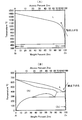
- Si is added to Zn, as shown in FIG. 18 (A)
- the melting point of the material rises with the addition of Si and increases to about 600 to 900 ° C. Therefore, Si is a Zn-based brazing material.
- It has not been studied as an additive element.
- Al that lowers the melting point of the brazing filler metal by eutectic with Zn as shown in FIG. 18B is usually used.
- 18A is a binary equilibrium diagram of ZnSi
- FIG. 18B is a binary equilibrium diagram of ZnAl (source: BinaryAlloyPhaseDiagrams, ASMInternational, MaterialsPark).
- the present inventor has confirmed that by using a Zn—Si brazing material containing Si as an additive element, an intermetallic compound layer is not formed at the boundary between the Fe-based metal member and the bonding layer. I found it.
- the brazing material is a brazing material used for joining an Fe-based metal member made of an Fe-based material and an Al-based metal member made of an Al-based material, wherein Zn, It consists of Si and inevitable impurities.
- an Fe-based metal member made of an Fe-based material and an Al-based metal member made of an Al-based material are joined to each other.
- An intermetallic compound layer is not formed at the boundary between the metal member and the bonding layer.
- the intermetallic compound layer at the boundary between the Fe-based metal member and the bonding layer is fragile, the strength of the bonded structure has been reduced.
- a Zn—Si-based brazing material such an intermetallic compound is used. Since no layer is formed, the strength of the boundary between the Fe-based metal member and the bonding layer can be increased. As a result, it is possible to obtain a bonding strength substantially equivalent to that of the same type metal member bonding.
- Si may be contained in an amount of 0.25 to 2.5% by weight, with the balance being Zn and inevitable impurities.
- the bonding strength (particularly peel strength) can be further improved.
- the metal member joining method includes interposing a brazing material between an Fe-based metal member made of Fe-based material and an Al-based metal member made of Al-based material.
- the Fe-based metal member of the bonded portion can be heated at a temperature equal to or higher than the melting point of the Fe-based material.
- a keyhole can be formed in the bonded portion of the Fe-based metal member during bonding.
- the keyhole is a cavity formed by melting a metal member.
- a to-be-joined part represents the joining plan part of an Fe-type metal member and an Al-type metal member, and a joining part represents the joining plan part after joining.
- the molten Zn—Si brazing material that has entered the keyhole after heating the welded portion can uniformly react with the entire surface of the keyhole. Therefore, since the strength of the boundary portion between the Fe-based metal member and the bonding layer can be further increased, the bonding strength of the bonded structure can be further improved.
- the Zn-based material and the Fe—Zn-based material are vaporized.
- the plated portion applied to the Fe-based material is vaporized, so that a good joint can be obtained regardless of the type of plating.
- the oxide film on the surface of the Fe-based material is removed by the vapor pressure during melting and vaporization due to overheating, the dissimilar metal member can be satisfactorily bonded without using a flux.
- a brittle intermetallic compound layer is not formed at the boundary between the Fe-based metal member and the bonding layer.
- the strength of the boundary portion between the metallic metal member and the bonding layer can be increased, and as a result, the bonded structure can obtain an effect such as being able to obtain approximately the same bonding strength as the same kind of metal member bonding.
- one or more embodiments of the present invention provide a metal member joining method capable of improving the joining strength by preventing the occurrence of thermal history for each part at the boundary part of the joined parts of the dissimilar metal members. I will provide a.
- an Fe-based metal member made of an Fe-based material and an Al-based material are used as the metal members.
- an Al-based metal member made of Zn using a Zn-based brazing material as a brazing material, in joining an Fe-based metal member and an Al-based metal member, the brazing material is evaporated by laser beam irradiation and the metal member is welded The part is melted to form a keyhole, and the laser beam is subjected to multiple reflection in the keyhole.
- the keyhole is a cavity formed by melting a metal member.
- the following to-be-joined part represents the joining plan part of a Fe-type metal member and an Al-type metal member, and a joining part represents the joining plan part after joining.
- the brazing material is evaporated by laser beam irradiation, and the welded portion of the metal member is melted to form a keyhole.
- the evaporated brazing material fills the keyhole, and the other brazing material is present along with the molten metal around the upper end of the keyhole. These molten materials enter the keyhole after the welded portion is heated and form a reaction layer.
- the laser beam is multiply reflected in the keyhole, so the energy density increases in the keyhole, and the entire surface from the upper side to the lower side of the keyhole is heated substantially uniformly.
- the molten material that enters the keyhole after the welded portion is heated can react uniformly with the entire surface of the keyhole.
- the molten material that enters the keyhole can be instantaneously solidified, so that the boundary between the Fe-based metal member and the bonding layer can be cooled uniformly. .
- the reaction layer becomes a uniform layer, so that the bonding strength can be improved.
- a reaction layer is not formed between the Fe-based metal member and the bonding layer, such a fragile layer does not exist, and unevenness is present in the strength distribution at the boundary between the Fe-based metal member and the bonding layer. Since it does not occur, the bonding strength can be greatly improved.
- the joint area is increased accordingly, so that the above effect can be obtained better.
- Zn-based plating and alloyed Fe—Zn-based plating are vaporized.
- the plated portion applied to the Fe-based material is vaporized regardless of the type of plating such as GA plating and GI plating.
- a good joint can be obtained regardless of the type of plating.
- the oxide film on the surface of the Fe-based material is removed by the vapor pressure during melting and vaporization due to overheating, the dissimilar metal member can be satisfactorily bonded without using a flux.
- the region of the joining temperature is limited to a predetermined region, unlike the case of the same kind of metal member, so that the entire surface from the upper side to the lower side of the keyhole can be heated substantially uniformly.
- the joining method of the metal member of the embodiment is particularly effective for joining of dissimilar metal members in which the region of the joining temperature is limited to a predetermined region, and the above effect is compared with the joining of conventional dissimilar metal members, It will be remarkable.
- an Fe-based metal member made of an Fe-based material and Al Using an Al-based metal member made of an Al-based material, using a Zn-based brazing material as a brazing material, forming a groove shape with an Fe-based metal member and an Al-based metal member, In joining, the brazing material is evaporated by irradiation with the laser beam, and the laser beam is subjected to multiple reflection on the groove-shaped surface.
- the welded portion of the metal member is not melted, and Fe-based Multiple reflection of the laser beam is performed within a groove shape formed of a metal member and an Al-based metal member.
- Fe-based Multiple reflection of the laser beam is performed within a groove shape formed of a metal member and an Al-based metal member.
- the entire surface can be heated substantially uniformly by multiple reflection of the laser beam in the keyhole or the groove-shaped surface.
- the effect that the joint strength of the boundary part of a metal member and a joining layer can be improved can be acquired.
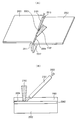
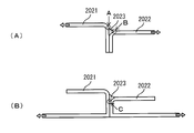
- FIG. 1A and 1B show a state in which a bonded structure is manufactured by the metal member bonding method according to the first embodiment.
- FIG. 1A is a schematic perspective view
- FIG. It is a side view of a to-be-joined part.
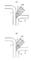
- 2A and 2B show examples of the state of irradiation of the laser beam to the bonded portion of the metal member in FIGS. 1A and 1B
- FIG. FIG. 2B is an enlarged front view when the center line of the beam is coincident with the center line of the groove shape of the metal member
- FIG. 2B is an Fe-based metal from the center line of the groove shape of the metal member. It is an enlarged front view in the case of offset to the member side.
- FIG. 1A is a schematic perspective view
- FIG. It is a side view of a to-be-joined part.
- 2A and 2B show examples of the state of irradiation of the laser beam to the bonded portion of the metal member in FIGS
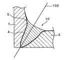
- FIG. 3 is a configuration diagram illustrating a bonded structure of metal members according to the first embodiment.
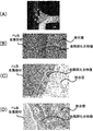
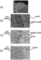
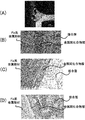
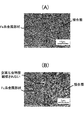
- 4 (A) to 4 (D) are SEM photographs of the joint structure of the metal member of Example 1 of the first embodiment
- FIG. 4 (A) is an overall photograph of the joint and its vicinity
- FIG. (B) is a photograph of the upper part of the bonding interface between the Fe-based metal member and the bonding layer
- FIG. 4 (C) is a photograph of the central part of the bonding interface between the Fe-based metal member and the bonding layer
- FIG. 4 (D) are the photographs of the lower part of the joint interface part of a Fe-type metal member and a joining layer.
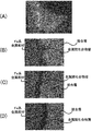
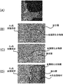
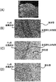
- FIG. 5 (A) to 5 (D) are SEM photographs of the joint structure of the metal member of Example 2 of the first embodiment
- FIG. 5 (A) is an overall photograph of the joint and its vicinity
- FIG. (B) is a photograph of the upper part of the bonding interface between the Fe-based metal member and the bonding layer
- FIG. 5 (C) is a photograph of the central part of the bonding interface between the Fe-based metal member and the bonding layer
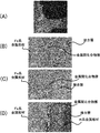
- FIG. 5 (D) are SEM photographs of the joint structure of the metal member of Example 3 of the first embodiment
- FIG. 6 (A) is an overall photograph of the joint and its vicinity
- FIG. (B) is a photograph of the upper part of the bonding interface between the Fe-based metal member and the bonding layer
- FIG. 6 (C) is a photograph of the central part of the bonding interface between the Fe-based metal member and the bonding layer
- FIG. 6 (D) are SEM photographs of the bonded structure of the metal member of Comparative Example 1
- FIG. 7 (A) is an overall photograph of the joint and its vicinity
- FIG. 7 (B) is Fe.
- FIG. 7C is a photograph of the upper part of the joining interface between the metallic metal member and the joining layer
- FIG. 7C is a photograph of the central part of the joining interface between the Fe based metallic member and the joining layer
- FIG. 7D is an Fe based metallic member. It is the photograph of the lower part of the junction interface part of a and a joining layer.
- 8 (A) to 8 (D) are SEM photographs of the joint structure of the metal member of Comparative Example 2
- FIG. 8 (A) is a whole photograph of the joint and its vicinity
- FIG. 8 (B) is Fe.
- 8C is a photograph of the upper part of the joining interface between the metallic metal member and the joining layer
- FIG. 8C is a photograph of the central part of the joining interface between the Fe based metallic member and the joining layer
- FIG. 8D is an Fe based metallic member. It is the photograph of the lower part of the junction interface part of a and a joining layer.
- 9 (A) to 9 (D) are SEM photographs of the joint structure of the metal member of Comparative Example 3
- FIG. 9 (A) is an overall photograph of the joint and its vicinity
- FIG. 9 (B) is Fe
- 9C is a photograph of the upper part of the joining interface between the metallic metal member and the joining layer
- FIG. 9C is a photograph of the central part of the joining interface between the Fe based metallic member and the joining layer
- FIG. 9D is an Fe based metallic member.
- FIG. 10 (A) and 10 (B) show a schematic configuration in a state where a joined structure is manufactured by the joining method of metal members of the second embodiment
- FIG. 10 (A) is a perspective view
- FIG. 10 (B) Is a side view
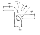
- FIG. 11 is a cross-sectional view illustrating a configuration of a bonded portion in which a keyhole is formed when the metal member of the second embodiment is bonded
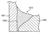
- FIG. 12 is a cross-sectional configuration diagram illustrating an example of a bonded structure obtained by the metal member bonding method of the second embodiment.
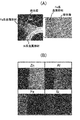
- FIG. 13A is an SEM photograph (left photograph) of the joint portion of the joint structure and an enlarged SEM photograph (right photograph) of the interface between the Fe-based metal member and the joining layer in the photograph.
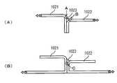
- FIG. These are the EPMA map analysis photographs of the interface shown by the enlarged photograph of FIG. 14 (A) and 14 (B) are SEM photographs of the interface between the Fe-based metal member and the bonding layer, FIG. 14 (A) is a 3000 times SEM photograph, and FIG. 14 (B) is a 15000 times SEM. It is a photograph. 15 (A) and 15 (B) are schematic cross-sectional configuration diagrams of a joined structure for explaining the methods of the flare tensile strength test and the peel strength test. FIG.
- FIG. 16 is a graph showing the strength of each sample obtained in the flare tensile strength test.
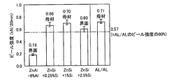
- FIG. 17 is a graph showing the strength of each sample obtained in the peel strength test.
- 18A is a binary equilibrium diagram of ZnSi
- FIG. 18B is a binary equilibrium diagram of ZnAl.
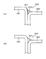
- FIGS. 19 (A) and 19 (B) show a schematic configuration in a state in which a joined structure is manufactured by the method of joining metal members of the third embodiment
- FIG. 19 (A) is a perspective view
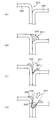
- FIG. 19 (B) show a schematic configuration of the metal member joining method of the third embodiment
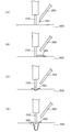
- FIGS. 20A to 20D are the same as FIG. 19B in each step.
- FIGS. 21 (A) to 21 (D) are front views of FIG. 19 (A) for each step.
- 22A and 22B are cross-sectional configuration diagrams showing an example of a bonded structure obtained by the metal member bonding method of the third embodiment.
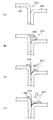
- 23 (A) to 23 (D) show a schematic configuration of the metal member joining method of the fourth embodiment, and FIGS. 23 (A) to 23 (D) are front views of FIG. 19 (A) for each step. It is the schematic seen from.
- 24A and 24B are cross-sectional configuration diagrams illustrating an example of a bonded structure obtained by the metal member bonding method of the fourth embodiment.
- 25 (A) to 25 (D) are SEM photographs of the joint structure of the metal member of the sample of Example 1
- FIG. 25 (A) is a whole photograph of the joint and its vicinity
- FIG. 25 (B) Is a photograph of the upper part of the bonding interface between the Fe-based metal member and the bonding layer
- FIG. 25C is a photograph of the central part of the bonding interface between the Fe-based metal member and the bonding layer
- FIG. It is a photograph of the lower part of the joining interface part of a metal member and a joining layer.
- FIG. 26 (A) to 25 (D) are SEM photographs of the joint structure of the metal member of the comparative sample of Example 1, and FIG. 26 (A) is an overall photograph of the joint and its vicinity, FIG. B) is a photograph of the upper part of the bonding interface between the Fe-based metal member and the bonding layer, FIG. 26C is a photograph of the central part of the bonding interface between the Fe-based metal member and the bonding layer, and FIG. It is a photograph of the lower part of the joining interface part of a Fe-type metal member and a joining layer.
- 27 (A) to 25 (D) are SEM photographs of the bonded structure of the metal member of the comparative sample of Example 1 and FIG. 27 (A) is an overall photograph of the bonded portion and its vicinity, FIG.
- FIG. 28A is an SEM photograph (left photograph) of the joint portion of the joint structure of Example 2, and an enlarged SEM photograph (right photograph) of the interface between the Fe-based metal member and the joining layer in the photograph.
- 28 (B) is an EPMA map analysis photograph of the interface shown in the enlarged photograph of FIG. 28 (A).
- FIG. 29 (A) and 29 (B) are SEM photographs of the interface between the Fe-based metal member and the bonding layer of Example 2
- FIG. 29 (A) is a 3000 times SEM photograph
- FIG. 29 (B) is a photograph. It is a SEM photograph of 15000 times.
- 30 (A) and 30 (B) are schematic cross-sectional configuration diagrams of a joined structure for explaining a method of a flare tensile strength test and a peel strength test in Example 2.
- FIG. 3 is a graph showing the strength of each sample obtained in the flare tensile strength test of Example 2.
- FIG. 4 is a graph showing the strength of each sample obtained in the peel strength test of Example 2.
- FIG. 1 (A) and 1 (B) show a state in which the metal member is joined using the joining method of the first embodiment
- FIG. 1 (A) is a schematic perspective view
- FIG. 1 (B) Is a schematic front view.
- 2A and 2B show examples of the state of irradiation of the laser beam to the bonded portion of the metal member in FIGS. 1A and 1B
- FIG. FIG. 2B is an enlarged front view when the center line of the beam is coincident with the center line of the groove shape of the metal member
- FIG. 2B is an Fe-based metal from the center line of the groove shape of the metal member. It is an enlarged front view in the case of offset to the member side.
- the metal member joining method uses, for example, an arrangement for producing a flare joint.
- an Fe-based metal member 1 made of Fe-based material and an Al-based metal member 2 made of Al-based material are used as the metal member.
- the Fe-based metal member 1 and the Al-based metal member 2 have curved portions 11 and 12.
- the curved portions 11, 12 face each other, and a groove shape 13 is formed by the curved portions 11, 12.
- a step is provided at the facing portion between the Fe-based metal member 1 and the Al-based metal member 2.
- a wire-like Zn-based brazing material 3 is formed at the center of the groove shape 13 formed by the curved portions 11 and 12 of the Fe-based metal member 1 and the Al-based metal member 2.
- the laser beam 102 is irradiated to the tip portion of the Zn-based brazing material 3 while feeding the wire through the wire guide 101.
- the Zn-based brazing material 3 only needs to contain Zn as a main component, and may or may not contain Al.
- the bonded portion of the Fe-based metal member 1 is heated at a temperature equal to or higher than the melting point of the Fe-based material that is a constituent material thereof.
- the center line l of the laser beam 102 may coincide with the center line of the groove shape 13, but as shown in FIG.
- the center line l ′ is preferably positioned closer to the Fe-based metal member 1 than the center line of the groove shape 13.
- l in FIG. 2B indicates the center line of the laser beam 102 in FIG.
- the to-be-joined part of the Fe-type metal member 1 is heated so that a keyhole is formed in the Fe-type metal member 1. In this case, by supplying the shielding gas to the bonded portion, the bonded portion is shielded from the atmosphere.
- the joint structure 10 with the metal member 2 can be manufactured.
- the path of the laser beam 102 irradiated at the time of bonding is shown.
- the joint structure 10 includes an Fe-based metal member 1 and an Al-based metal member 2. Between the Fe-based metal member 1 and the Al-based metal member 2, a Zn—Al-based material containing Zn as a main component and Al. A bonding layer 4 made of is formed. An intermetallic compound layer 5 made of an Al—Fe—Zn intermetallic compound containing Al as a main component is formed at the boundary between the Fe-based metal member 1 and the bonding layer 4. Since Al of the Al-based metal member flows into the joining layer 4 by welding, even when the Zn-based brazing material 3 does not contain Al, the joining layer 4 and the intermetallic compound layer 5 contain Al.
- the intermetallic compound layer 5 is preferably formed along the entire interface of the boundary portion between the Fe-based metal member 1 and the bonding layer 4.
- the composition ratio is preferably Al: 40 to 60%, Fe: 30 to 40%, and Zn: 10 to 25%.
- the intermetallic compound layer 5 is considered to have the following actions and effects. That is, the intermetallic compound layer 5 has an action of suppressing the reaction between Fe and Al, and the action prevents the inflow of Al into the Fe-based metal member 1 and the inflow of Fe into the Al-based metal member 2. It is presumed that
- the bonded portion of the Fe-based metal member 1 is heated at a temperature equal to or higher than the melting point of the Fe-based material, so that the bonding layer 4 composed of the Fe-based metal member 1 and the Zn-based brazing material 3
- An intermetallic compound layer 5 made of an Al—Fe—Zn-based intermetallic compound containing Al as a main component can be formed at the boundary portion. Since the intermetallic compound layer 5 has high ductility, the bonding strength between the Fe-based metal member 1 and the bonding layer 4 can be increased. Therefore, the joint strength between the Fe-based metal member 1 and the Al-based metal member 2 can be improved.
- the Zn-based material and the Fe—Zn-based material are vaporized.
- the type of plating such as GA plating or GI plating
- the plated portion applied to the Fe-based material is vaporized, so that a good joint can be obtained regardless of the type of plating.
- the oxide film on the surface of the Fe-based material is removed by the vapor pressure at the time of melting and vaporization due to overheating, good dissimilar material joining can be performed without using a flux.
- the Fe-based material of the Fe-based metal member 1 is mainly melted by positioning the center line l ′ of the laser beam 102 closer to the Fe-based metal member 1 than the center of the groove shape 13. Therefore, the intermetallic compound layer 5 can be formed in a stable layer shape at the entire boundary portion between the Fe-based metal member 1 and the bonding layer 4. Moreover, since the Al-based material of the Al-based metal member 2 is not excessively heated, it is possible to prevent the Al-based material from being melted down. Therefore, the joint strength between the Fe-based metal member 1 and the Al-based metal member 2 can be further improved.
- the Zn-based brazing material 3 is formed in the molten portion of the Fe-based metal member 1 at the time of bonding. Inflow. Thereby, the shape in which the bonding layer 4 is fitted to the Fe-based metal member 1 can be obtained.
- the laser is multiply reflected in the keyhole, the energy density is high and the temperature of the inner surface of the keyhole is kept uniform. Thereby, the metal compound layer 5 can be formed uniformly over the upper part, the center part, and the lower part of the joint part. Therefore, since the joining strength between the Fe-based metal member 1 and the joining layer 4 can be further increased, the joining strength between the Fe-based metal member 1 and the Al-based metal member 2 can be further improved.
- Example 1 to 3 and Comparative Examples 1 to 3 two metal members are arranged in the same manner as the arrangement shown in FIGS. 1A and 1B, and the groove shape is formed by the curved portions of the metal members. Formed. And the laser beam was irradiated to the front-end
- the joining conditions in Examples 1 and 2 and Comparative Examples 1 to 3 were as shown in Table 1.
- the notation of Fe / Al indicates that a steel plate that is an Fe-based metal member and an Al alloy plate that is an Al-based metal member are used as two metal members, and the notation of Fe / Fe is It shows that steel plates that are both Fe-based metal members were used as the two metal members.
- ZnAl indicates that a composition ratio (wt%) ZnAl-based brazing material (including unavoidable impurities) having a Zn: Al ratio of 96: 4 was used. This shows that a Zn-based brazing material (including inevitable impurities) of 100 wt% was used.
- the notation of the center indicates that the center line of the laser beam coincides with the center line of the groove shape of the two metal members (arrangement of FIG. 2A), and the Fe-based metal member
- the notation “side” indicates that the center line of the laser beam is offset by 0.6 mm from the groove-shaped center line to the Fe-based metal member side (arrangement in FIG. 2B).
- the size of the two metal members is 82 mm in the horizontal direction in FIG. 1 and 200 mm in the vertical direction in FIG. And the level difference at the joined portion of the two metal members was 5 mm.
- Ar gas was used as the shielding gas, and its supply rate was 25 l / min.
- the irradiation angle of the laser beam was 40 °.
- FIG. 4 to 9 are SEM photographs of the bonded structures of the metal members of Examples 1 to 3 and Comparative Examples 1 to 3.
- (D) is a photograph of the lower part R of the bonding interface between the Fe-based metal member and the bonding layer.
- Table 2 since the strength of the A1-based metal member itself used in the examples and comparative examples is about 240 N / m and the bonding strength between the A1-based metal members is about 140 N / mm, the strength determination is performed in each example and comparison. When the joint strength in the example is about 140 N / mm or more, the strength is indicated as “A”.
- the evaluation mark A means “good”, B means “problem”, and C means “bad”.
- Example 1 In the joining of Example 1, as shown in Table 1, an Fe-based metal member and an Al-based metal member are used as two metal members, and an appropriate heat input condition in which the joined portion of the Fe-based metal member is appropriately melted by heating. In the laser beam irradiation, the center line of the laser beam was offset by 0.6 mm from the groove-shaped center line of the two metal members toward the Fe-based metal member. In the joining structure of Example 1 obtained under such joining conditions, as shown in FIG. 4 and Table 2, the upper part P, the central part Q, and the lower part R of the joining interface part between the Fe-based metal member and the joining layer are provided.
- an intermetallic compound layer made of a stable layered Al—Fe—Zn-based intermetallic compound is formed, where Al: Fe: Zn is 52:29:19 (about 5: 3: 2). Most of them have a certain composition ratio.
- the composition ratio obtained by SEM analysis was 57:30:13 for Al: Fe: Zn.
- the joining strength of the joining structure of Example 1 was 154 N / mm.
- Example 2 In joining of Example 2, as shown in Table 1, an Fe-based metal member and an Al-based metal member are used as two metal members, and an appropriate heat input condition in which the joined portion of the Fe-based metal member is appropriately melted by heating. In the laser beam irradiation, the center line of the laser beam was made to coincide with the center line of the groove shape of the two metal members.
- Example 1 In the joining structure of Example 2 obtained under such joining conditions, as shown in FIG. 5 and Table 2, Example 1 is formed in the upper part P and lower part R of the joining interface between the Fe-based metal member and the joining layer. The interface between the intermetallic compound layer composed of an Al—Fe—Zn intermetallic compound and the bonding layer was unclear compared to the bonding structure of FIG.
- a stable layered intermetallic compound layer made of an Al—Fe—Zn-based intermetallic compound was formed in the central portion Q of the portion. There, most of them had a composition ratio of Al: Fe: Zn of 41:40:19.
- the bonding strength of the bonded structure of Example 2 was 96 N / mm.
- Example 3 In the bonding of Example 3, as shown in Table 1, the same bonding conditions as in Example 1 were used except that a Zn-based brazing material not containing Al was used as the brazing material, and laser beam irradiation was performed. .
- the upper part P, the central part Q, and the lower part R of the joining interface part between the Fe-based metal member and the joining layer are provided.
- an intermetallic compound layer made of a stable layered Al—Fe—Zn-based intermetallic compound is formed, and most of them have a composition ratio of Al: Fe: Zn of 58:23:19. Accounted for.
- the joining strength of the joining structure of Example 3 was 149 N / mm.
- Comparative Example 1 In the joining of Comparative Example 1, as shown in Table 1, using an Fe-based metal member and an Al-based metal member as the two metal members, the joined portion of the Fe-based metal member is in an insufficient heat input condition that does not melt by heating, In laser beam irradiation, the center line of the laser beam was made to coincide with the center line of the groove shape of the two metal members.
- a stable layered Al—Fe in the upper portion P of the bonding interface between the Fe-based metal member and the bonding layer.
- An intermetallic compound layer composed of a —Zn-based intermetallic compound was formed.
- the interface between the intermetallic compound layer made of an Al—Fe—Zn intermetallic compound and the bonding layer is unclear at the central portion Q of the bonding interface between the Fe-based metal member and the bonding layer.
- No intermetallic compound layer was formed in the lower part R of the film.
- the joining strength of the joining structure body of the comparative example 1 was 37 N / mm.
- the intermetallic compound layer was dendritic (no boundary surface) in the upper portion P, and was mottled (no boundary surface on the bonding layer side) in the central portion Q4 and the lower portion R.
- the bonding strength of the bonded structure of Comparative Example 2 was 30 N / mm.
- both of the two metal members are Fe-based metal members, and the heat input conditions are such that the bonded portion of the Fe-based metal member is appropriately heated and melted,
- the center line of the laser beam was offset by 0.6 mm from the groove-shaped center line of the two metal members toward the Fe-based metal member.
- the upper part P, the central part Q, and the lower part R of the joining interface part between the Fe-based metal member and the joining layer 1 an intermetallic compound layer made of an intermetallic compound containing Al, Fe, and Zn has been formed.
- the intermetallic compound layer was mottled in the upper part P and the central part Q (no boundary surface on the bonding layer side) and serpentine in the lower part R.
- the bonding strength of the bonded structure of Comparative Example 3 was 56 N / mm.
- the Fe-based metal member and the Al-based metal member are used as the metal members, and heating conditions for appropriately melting Fe are used.
- an intermetallic compound layer composed of an Al—Fe—Zn based intermetallic compound can be formed in all of the upper portion P to the lower portion R of the bonding interface between the Fe-based metal member and the bonding layer.
- the joint strength can be improved.
- the intermetallic compound layer became a stable layer regardless of the presence or absence of Al in the Zn-based brazing material.
- the composition ratio was confirmed to satisfy Al: 40 to 60%, Fe: 30 to 40%, and Zn: 10 to 25%.
- the position of laser beam irradiation is offset from the center of the groove shape toward the Fe-based metal member side, so that the Fe-based structure is compared with the joined structure of Example 2. It was confirmed that a stable layered Al—Fe—Zn-based intermetallic compound could be formed at all of the upper and lower portions of the bonding interface between the metal member and the bonding layer, and the joint strength could be improved. In addition, it was confirmed that the boundary between the Fe-based metal member and the bonding layer and the boundary between the Al-based metal member and the bonding layer became clearer as the intermetallic compound layer became more stable.
- the compound layer has an action of suppressing the reaction between Fe and Al, and the action can prevent the inflow of Al into the Fe-based metal member and the inflow of Fe into the Al-based metal member.
- FIG. 10 (A) and 10 (B) represent a schematic configuration in a state where the joining is performed using the metal member joining method of the second embodiment
- FIG. 10 (A) is a schematic perspective view
- FIG. B) is a front view.
- the metal member joining method uses, for example, an arrangement for producing a flare joint.
- an Fe-based metal member 1001 made of Fe-based material and an Al-based metal member 1002 made of Al-based material are used as the metal member.
- the Fe-based metal member 1 and the Al-based metal member 2 have curved portions 1011 and 1012.
- the curved portions 1011 and 1012 face each other, and a groove shape 1013 is formed by the curved portions 1011 and 1012.
- a step is provided at the facing portion between the Fe-based metal member 1001 and the Al-based metal member 1002.
- the wire-shaped Zn—Si brazing material 1003 is fed to the center of the groove shape 13 through the wire guide 1101, while the tip of the Zn—Si based brazing material 1003. Irradiation with a laser beam 1102 is performed.
- the Zn—Si based brazing material 1003 is made of Zn, Si, and inevitable impurities. In this case, it is preferable that Si contains 0.25 to 2.5% by weight, and the balance consists of Zn and inevitable impurities.
- FIG. 11 is a cross-sectional view illustrating a schematic configuration of a bonded portion in which a keyhole 1005 is formed when the Fe-based metal member 1001 and the Al-based metal member 1002 are bonded.
- the material is melted and evaporated by heating, and a keyhole 1005 is formed by an evaporation reaction force (arrow in the figure) due to the evaporated material.
- the molten Zn—Si brazing material is present around the laser irradiation portion.
- the laser beam 1102 is multiple-reflected as indicated by the dotted line in the figure, so that the energy density is high in the keyhole 1005, and the entire surface from the upper side to the lower side in the keyhole 1005 Is heated substantially uniformly. Accordingly, the molten Zn—Si brazing material that enters the keyhole 1005 after passing the laser beam 1102 can uniformly react with the entire surface in the keyhole 1005.
- the Fe-based metal member 1001 and the Al-based material A bonded structure 1010 with the metal member 1002 can be manufactured.
- the bonding structure 1010 includes an Fe-based metal member 1 and an Al-based metal member 1002, and a bonding layer 1004 made of a Zn—Si-based material is formed between the Fe-based metal member 1001 and the Al-based metal member 1002. ing.
- a bonding layer 1004 made of a Zn—Si-based material is formed between the Fe-based metal member 1001 and the Al-based metal member 1002.
- the bonding layer 1004 it is preferable that Si particles are scattered in the matrix and the particle size is smaller.
- the Si particle size is preferably a size that does not inhibit the mechanical elongation of Zn (for example, 10 ⁇ m or less).
- the atomization of Si grains is presumed to be performed by cutting the crystal grains during the extrusion process in the production of the brazing material.
- the bonded structure 1010 can obtain approximately the same bonding strength as the same-type metal member bonding.
- the Zn—Si based brazing material 1003 a brazing material containing 0.25 to 2.5% by weight of Si and the balance of Zn and inevitable impurities is used, so that (especially peel strength) is further improved. Can be made.
- the molten Zn—Si brazing material that has entered the keyhole 1005 formed in the bonded portion of the Fe-based metal member 1001 after heating can react uniformly with the entire surface of the keyhole 5. Further, the strength of the boundary portion between the Fe-based metal member 1001 and the bonding layer 1004 can be further increased. As a result, the joint strength of the joint structure 1010 can be further improved.
- the Zn-based material and the Fe—Zn-based material are vaporized.
- the plated portion applied to the Fe-based material is vaporized, so that a good joint can be obtained regardless of the type of plating.
- the oxide film on the surface of the Fe-based material is removed by the vapor pressure during melting and vaporization due to overheating, the dissimilar metal member can be satisfactorily bonded without using a flux.
- Fe-based metal members and Al-based metal members were disposed in the same manner as in the arrangement form shown in FIG. 10, and a groove shape was formed by the curved portions of these metal members.
- the tip of the Zn—Si brazing material was irradiated with a laser beam while a wire-like Zn—Si brazing material was delivered to the center of the groove shape through a wire guide. Thereby, a bonded structure of metal members having a flare joint shape was manufactured.
- the focused diameter of the laser beam was 1.8 mm
- the laser output was 1.4 kW
- the bonding speed was 1 m / min
- the wire speed was 3.2 m / min.
- a steel plate (JAC270, plate thickness 1.0 mm, longitudinal length 200 mm, lateral length 80 mm in FIG. 1) was used as the Fe-based metal member, and Al plate (A6K21-T14, plate thickness) as the Al-based metal member.
- the longitudinal length in FIG. 1 is 200 mm
- the lateral length is 80 mm).
- Zn—Si based brazing materials having different Si contents are prepared, and each Zn—Si is prepared.
- the metal member was joined using the brazing filler metal to obtain a joined structure of metal members corresponding to each Zn—Si brazing filler metal.
- each joining structure was cut
- the wire diameter of all Zn—Si brazing materials was 1.2 mm.
- Various evaluations were performed using the test piece of the bonded structure as described above.
- FIGS. 13 (A) and 13 (B) A test piece of a bonded structure obtained using a Zn—Si brazing material having an Si content of 1.0 wt% was subjected to elemental analysis using an electron beam microprobe analyzer (EPMA). The results are shown in FIGS. 13 (A) and 13 (B).
- FIG. 13A is an SEM photograph (left photograph) of the joint portion of the joint structure and an enlarged SEM photograph (right photograph) of the interface between the Fe-based metal member and the joining layer in the photograph.
- FIG. It is the EPMA map analysis photograph (Zn, Al, Fe, Si) of the interface shown by the enlarged SEM photograph of FIG. 13 (A).
- FIGS. 14 (A) and 14 (B) are SEM photographs of the interface between the Fe-based metal member and the bonding layer, FIG. 14 (A) is a 3000 times SEM photograph, and FIG. 14 (B) is a 15000 times SEM. It is a photograph.
- the intermetallic compound layer formed in the conventional bonded structure was not observed at the interface between the Fe-based metal member of the present example and the bonding layer.
- Si was uniformly dispersed and the interface between Fe and Zn (that is, the interface between the Fe-based metal member and the bonding layer) was clearly observed.
- Al is a solution in which Al of the Al-based metal member is dissolved in the joining layer by welding.
- the Fe-based metal member of this example At the interface with the bonding layer, the intermetallic compound layer formed with the conventional bonding structure was not observed.
- the interface between the Fe-based metal member and the bonding layer of the example of the present invention is formed of a bonded structure bonded by a Zn—Al-based brazing material. It was confirmed that there was no fragile intermetallic compound layer.
- Flare tensile strength test and peel strength test were performed on test pieces of each joint structure obtained using Zn-Si brazing filler metals having Si content of 0.25 wt%, 1.0 wt%, and 2.5 wt%. It was. As test pieces, 2 pieces on the center side of the joint structure and 4 pieces on both ends are allocated for each strength test, and the center side in each of the flare tensile strength test and the peel strength test. 1 piece and 2 pieces (total 3 pieces) on both ends were used.
- the results are shown in Table 3 and FIG.
- Table 3 the test results of the test pieces of the joint structure corresponding to the Zn—Si brazing material having the Si content of 0.25 wt%, 1.0 wt%, and 2.5 wt% are shown as Samples 11-13.
- Table 3 shows the results of the comparative samples 11 and 12 together.
- the comparative sample 11 is a test piece of a joined structure of an Fe-based metal member and an Al-based metal member obtained using a Zn—Al-based brazing material with an Al addition amount of 6 wt% as a brazing material.
- the comparative sample 12 is a test piece of a joined structure of Al-based metal members obtained using a commercially available brazing material as the brazing material.
- the test pieces of the comparative samples 11 and 12 are obtained by cutting the obtained bonded structure into strips like the samples 11 to 13. In FIG. 16, the average value of the flare tensile strength of each sample and the fracture location are also shown.
- the strength reference value of the flare tensile strength test (the chain line in FIG. 16) is set as follows.
- the joint length of continuous welding equivalent to one spot welding spot was set to 20 mm, and spot welding of Al in JISZ3140 was used as a reference.
- spot welding of Al in JISZ3140 was used as a reference.
- the tensile strength standard of spot welding in which the plate thickness of Al is 1.2 mm is 1.86 kN / 20 mm.
- the tensile strength of the samples 11 to 13 of the second embodiment exceeded the strength reference value.
- the tensile strengths of the samples 11 to 13 of the second embodiment are higher than the tensile strength of the comparative sample 11 which is a joined structure of different kinds of metal members. It was higher than the tensile strength of Sample 12. Then, it was confirmed that the tensile strength was greatly improved with a small amount of Si content (0.25 wt%). Also, in the samples 11 to 13 of the second embodiment, it was confirmed that the fracture was caused by the Al-based metal member, unlike the comparative sample 11 fractured at the interface between the Fe-based metal member and the bonding layer.
- the results are shown in Table 4 and FIG.
- Table 4 the test results of the test pieces of the joined structure corresponding to the Zn—Si brazing material having the Si content of 0.25 wt%, 1.0 wt%, and 2.5 wt% are shown as Samples 21 to 23.
- Table 4 also shows the results of Comparative Samples 21 and 22.
- the comparative sample 21 is a test piece of a joined structure of an Fe-based metal member and an Al-based metal member obtained using a Zn—Al-based brazing material having an Al content of 6 wt% as a brazing material.
- the comparative sample 22 is a test piece of a joined structure of Al-based metal members obtained by using a commercially available brazing material as a brazing material.
- the test pieces of the comparative samples 21 and 22 are obtained by cutting the obtained bonded structure into strips like the samples 21 to 23. In FIG. 17, the average value of the peel strength of each sample and the fracture location are also shown.
- the strength reference value of the peel strength test (the one-dot chain line in FIG. 17) is a test of comparative sample 22 (joint structure of Al metal member) which is a joint structure of the same kind of metal member obtained using a commercially available brazing material. 80% of the peel strength value of the piece.
- the peel strength exceeded the strength standard.
- the peel strength of the samples 21 to 23 of the second embodiment is greatly reduced with a small amount of Si content (0.25 wt%) compared with the comparative sample 21 which is a bonded structure of dissimilar metal members. Confirmed improvement.
- the comparative sample 21 fractured ruptured in the interface of a Fe-type metal member and a joining layer
- an Al-type metal member It was confirmed that the rupture occurred.
- the peel interface width is reduced due to a decrease in wettability, so that the peel strength is slightly lower than that of the samples 21 and 22 of the second embodiment. It is inferred that the fracture occurred at the interface of the layers.
- the strength of the sample of the present invention which is a joined structure of dissimilar metal members using a Zn—Si brazing material having a Si content of 0.25 wt% to 2.5 wt%, exceeds the strength reference value. It was. Moreover, the strength of the sample of the second embodiment is found to be significantly improved with a small amount of Si content (0.25 wt%) by comparison with a comparative sample that is a joint structure of the same dissimilar metal member. It was.
- the sample of the present invention which is a bonded structure of dissimilar metal members using a Zn—Si brazing material having a Si content of 0.25 wt% to 1.0 wt%, at the interface between the Fe metal member and the bonding layer, Since it was not broken but was broken with an Al-based metal member, it was found that a strong bonded structure such as a bonded structure of the same metal member could be obtained.
- a laser is used.
- the present invention is not limited to this, and various means can be used. Specifically, arc blazing using plasma, TIG, and MIG as heat sources, brazing in a furnace (joining using a brazing (sheet-shaped or rod-shaped brazing) in a heating furnace), high-frequency brazing (high-frequency induction) (Base material heating by heating (IH)) or the like can be used.
- FIG. 19A and 19B show a schematic configuration in a state where the metal member is bonded using the metal member bonding method of the third embodiment.
- FIG. 19A is a schematic perspective view
- FIG. 19B is a view as seen from the Al-based metal member 2002 in FIG.
- the metal member joining method uses, for example, an arrangement for producing a flare joint.
- an Fe-based metal member 2001 made of Fe-based material and an Al-based metal member 2002 made of Al-based material are used as the metal member.
- the Fe-based metal member 2001 and the Al-based metal member 2002 have curved portions 2011 and 2012.
- the curved portions 2011 and 2012 face each other, and a groove shape 2013 is formed by the curved portions 2011 and 2012.
- a step is provided at the facing portion between the Fe-based metal member 2001 and the Al-based metal member 2002.
- a wire-shaped Zn-based brazing material 2003 is delivered through the wire guide 2101 to the central portion of the groove shape 2013, and the laser beam 2102 is irradiated to the tip portion.
- the Zn-based brazing material 2003 is preferable because sufficient bonding strength can be obtained as compared with the Sn-based brazing material.
- the Zn-based brazing material 2003 may or may not contain Al or Si as an additive element. When Si is used as the additive element, it is preferable that Si contains 0.25 to 2.5% by weight, with the balance being Zn and inevitable impurities.
- FIG. 21A to FIG. 21D are schematic views of each process as viewed from the front of FIG. 19A.
- the laser beam 2102 is moved to the right side of the drawing according to the process order.
- the illustration of the Fe-based metal member 1 is omitted.
- FIGS. 19 (A) and 20 (A) when the Zn-based brazing material 2003 is melted by irradiation with a laser beam 2102, as shown in FIGS. 19 (B) and 20 (B), molten Zn The brazing filler metal 2003 is dropped on the groove shape 2013 and expands there.
- FIGS. 19C and 20C when the laser beam 2102 moves and is positioned on the molten Zn-based brazing material 2003, the molten Zn-based brazing material 2003 is directly irradiated by the laser beam 2102. As it evaporates, melting of the joined portion of the Fe-based metal member 2001 and the Al-based metal member 2002 is started, and as shown in FIGS. 19D and 20D, the Fe-based metal member 2001 and the Al-based metal member. A keyhole 2005 is formed in the joined portion of 2002.
- the keyhole 2005 is formed so that the evaporated Zn-based brazing material 2003 fills the keyhole 2005.
- the Zn-based brazing material 2003 other than the evaporated portion exists as a molten material 2006 around the upper end portion of the keyhole 2005 together with the molten Fe-based metal member 2001 and the Al-based metal member 2002 (molten metal).
- the laser beam 2102 is multiple-reflected as indicated by the dotted line in the figure, so that the energy density increases in the keyhole 2005, and the entire surface from the upper side to the lower side in the keyhole 5 is increased. Is heated substantially uniformly.
- the molten material 2006 that enters the keyhole 2005 after the laser beam 2102 passes can react uniformly with the entire surface in the keyhole 2005.
- the bonding structure 2010 includes an Fe-based metal member 2001 and an Al-based metal member 2002, and a bonding layer 2004 made of a Zn-based material is formed between the Fe-based metal member 2001 and the Al-based metal member 2002. .
- a uniform layered intermetallic compound layer is formed at the boundary between the Fe-based metal member 2001 and the bonding layer 2004 as shown in FIG. 2007 is formed.
- the intermetallic compound layer 2007 has an action of suppressing the reaction between Fe and Al, and the action prevents the inflow of Al into the Fe-based metal member 2001 and the inflow of Fe into the Al-based metal member 2002. It is assumed that there is.
- an intermetallic compound layer (reaction layer) is formed at the boundary between the Fe-based metal member 1 and the bonding layer 2 as shown in FIG. not exist.
- the Si particle size is preferably a size that does not inhibit the mechanical elongation of Zn (for example, 10 ⁇ m or less).
- the entire surface from the upper side to the lower side of the keyhole 2005 is heated substantially uniformly by the multiple reflection of the laser beam 2102 in the keyhole 2005 during the heating of the welded portion. Therefore, the molten material 2006 entering the keyhole 2005 after the heating of the welded portion can uniformly react with the entire surface in the keyhole 2005. Further, since bonding at a low temperature is possible, the molten material 2006 entering the keyhole 2005 can be instantaneously solidified, so that the boundary between the Fe-based metal member 2001 and the bonding layer 2004 is uniformly cooled. be able to.
- the intermetallic compound layer 2007 when the intermetallic compound layer 2007 is formed between the Fe-based metal member 2001 and the bonding layer 2004, the intermetallic compound layer 2007 has a uniform layer shape, and thus the bonding strength can be improved. Further, when an intermetallic compound layer is not formed between the Fe-based metal member 2001 and the bonding layer 2004, such a fragile layer does not exist, and a boundary portion between the Fe-based metal member 2001 and the bonding layer 2004 is present. Since no unevenness is generated in the strength distribution, the bonding strength can be greatly improved.
- the joint area is increased correspondingly, so that the above effect can be obtained better.
- Zn-based plating and alloyed Fe—Zn-based plating are vaporized.
- the plated portion applied to the Fe-based material is vaporized regardless of the type of plating such as GA plating and GI plating.
- a good joint can be obtained regardless of the type of plating.
- the oxide film on the surface of the Fe-based material is removed by the vapor pressure during melting and vaporization due to overheating, the dissimilar metal member can be satisfactorily bonded without using a flux.
- ⁇ Fourth embodiment> instead of performing multiple reflection of the laser beam 2102 in the keyhole 2005 formed by melting the welded portion of the Fe-based metal member 1 and the Al-based metal member 2002 as in the third embodiment, The laser beam 2102 is subjected to multiple reflection within the groove shape 2013 formed by the Fe-based metal member 2001 and the Al-based metal member 2002 without melting the welded portion of the Fe-based metal member 2001 and the Al-based metal member 2002. Yes. Otherwise, the fourth embodiment is the same as the metal member joining method of the third embodiment. In the fourth embodiment, components similar to those in the third embodiment are denoted by the same reference numerals, and descriptions of components having the same functions as those in the third embodiment are omitted.
- FIGS. 23 (A) to 23 (D) show a schematic configuration of the metal member joining method of the fourth embodiment, and FIGS. 23 (A) to 23 (D) are the same as FIG. 19 (B) in each step. It is the schematic seen from the direction.
- the laser beam 2102 is moved to the right side of the drawing in the order of the steps.
- the molten Zn-based brazing material 2003 has a groove shape 2013. Drip on top and spread there.
- FIG. 23C when the laser beam 2102 moves and is positioned on the molten Zn-based brazing material 2003, the molten Zn-based brazing material 2003 is evaporated by direct irradiation with the laser beam 2102.
- the evaporated Zn-based brazing material 2003 is filled in the groove shape 2013.
- the Zn-based brazing material 2003 other than the evaporation portion is present around the upper end portion of the groove shape 2013. Since the laser beam 2102 is multiple-reflected on the surface in the groove shape 2013 as shown by the dotted line in the figure, the energy density is increased in the keyhole 2005, and the upper side from the upper side in the groove shape 2013 is lowered. The entire surface is heated substantially uniformly. Thus, the molten material 2006 that enters the keyhole 2005 after the laser beam 2102 passes can react uniformly with the entire surface in the keyhole 2005.
- the joint structure 2020 of the Fe-based metal member 2001 and the Al-based metal member 2002 can be manufactured.
- the bonding structure 2020 includes an Fe-based metal member 2001 and an Al-based metal member 2002, and a bonding layer 2014 made of a Zn-based material is formed between the Fe-based metal member 2001 and the Al-based metal member 2002. .
- multiple reflection of the laser beam 2102 is performed on the surface of the groove shape 2013 formed by the Fe-based metal member 1 and the Al-based metal member 2002, so that the entire surface in the groove shape 2013 is substantially uniform. Since it can heat, the effect by multiple reflection similar to 3rd Embodiment can be acquired.
- Example 1 when using a Zn—Al brazing material
- an Fe-based metal member and an Al-based metal member were disposed in the same manner as in the arrangement form shown in FIG. 19A, and a groove shape was formed by the curved portions of these metal members.
- the tip of the Zn—Al brazing material was irradiated with a laser beam while a wire-like Zn—Al brazing material was delivered to the center of the groove shape through a wire guide. Thereby, a bonded structure of metal members having a flare joint shape was manufactured.
- the size of the two metal members is such that the horizontal length in FIG. 19A is 82 mm and the vertical length in FIG. 19A is 200 mm.
- the level difference at 5 mm was 5 mm.
- a brazing material having a composition ratio (wt%) of Zn: Al of 96: 4 was used as the Zn—Al based brazing material.
- Ar gas was used as the shielding gas, the supply amount was 25 l / min, the laser beam irradiation angle was 40 °, and the joining speed was 1 m / min.
- the laser output and the wire speed are changed for each sample so that the keyhole formation state is different, and the joining structure (sample 111, comparative samples 111 and 112) of the metal member is used. Obtained.
- sample 111 the laser output is set to 1.2 kW, and the wire feed speed is set to 2.5 m / min, so that an appropriate heat input condition in which the bonded portion of the Fe-based metal member is melted by appropriate heating in the formation of the keyhole. It was.
- the laser output was set to 1 kW and the wire feed speed was set to 2 m / min, so that the heat input was insufficient under the condition that the bonded portion of the Fe-based metal member was not melted by heating in the formation of the keyhole.
- the laser output was set to 1.6 kW
- the wire feed speed was set to 2 m / min
- the heat input conditions were set such that the bonded portion of the Fe-based metal member was melted by excessive heating in forming the keyhole.
- any one of the upper part P, the central part Q, and the lower part R of the joining interface part between the Fe-based metal member and the joining layer in this case, any one of the upper part P, the central part Q, and the lower part R of the joining interface part between the Fe-based metal member and the joining layer.
- a stable layered intermetallic compound layer composed of an Al—Fe—Zn intermetallic compound is formed, and the boundary between the Fe-based metal member and the bonding layer and the boundary between the Al-based metal member and the bonding layer are formed. It became clear.
- the bonding strength of the bonded structure of Sample 11 was 154 N / mm.
- the upper part P, the central part Q, and the lower part R of the joining interface part between the Fe-based metal member and the joining layer As shown in FIG. 27, in the joined structure of the comparative sample 112 that has been subjected to excessive heat input conditions by forming a keyhole, the upper part P, the central part Q, and the lower part R of the joining interface part between the Fe-based metal member and the joining layer. 1, an intermetallic compound layer made of an intermetallic compound containing Al, Fe, and Zn has been formed. However, the intermetallic compound layer was dendritic in the upper portion P (no boundary surface) and mottled in the central portion Q4 and the lower portion R (no boundary surface on the bonding layer side). And the joining strength of the joining structure of the comparative sample 12 was 30 N / mm.
- the Fe-based metal member is compared with the bonded structure of the comparative samples 111 and 112 by multiple reflection of the laser beam under appropriate heat input conditions in forming the keyhole. It was confirmed that a uniform layered intermetallic compound layer can be formed in all of the upper part P to the lower part R of the joint interface portion between and the joint layer, and the joint strength can be improved. In particular, it was confirmed that the boundary between the Fe-based metal member and the bonding layer and the boundary between the Al-based metal member and the bonding layer became clearer as the intermetallic compound layer became more stable. It has been found that the layer has an action of suppressing the reaction between Fe and Al, and the action can prevent the inflow of Al into the Fe-based metal member and the inflow of Fe into the Al-based metal member.
- Example 2 (when using a Zn—Si brazing material)
- a flare joint-shaped metal member bonded structure was manufactured in the same manner as in Example 1 except that a Zn—Si based brazing material was used as the Zn based brazing material.
- the condensing diameter of the laser beam is 1.8 mm
- the laser output is 1.4 kW
- the bonding speed is 1 m / min
- the wire speed is 3.2 m / min.
- Appropriate heat input conditions were set such that the bonded parts were melted by appropriate heating.
- a steel plate (JAC270, plate thickness 1.0 mm, longitudinal length 200 mm, lateral length 80 mm in FIG. 19A) was used as the Fe-based metal member, and Al plate (A6K21-T14) as the Al-based metal member.
- the plate thickness was 1.0 mm
- the vertical length in FIG. 1 was 200 mm
- the horizontal length was 80 mm).
- Zn—Si based brazing materials having different Si contents are prepared, and each Zn—Si is prepared.
- the metal member was joined using the brazing filler metal to obtain a joined structure of metal members corresponding to each Zn—Si brazing filler metal.
- each joining structure was cut
- the wire diameter of all Zn—Si brazing materials was 1.2 mm.
- Various evaluations were performed using the test piece of the bonded structure as described above.
- FIGS. 28 (A) and 28 (B) A test piece of a bonded structure obtained using a Zn—Si brazing material having an Si content of 1.0 wt% was subjected to elemental analysis using an electron beam microprobe analyzer (EPMA). The results are shown in FIGS. 28 (A) and 28 (B).
- FIG. 28A is an SEM photograph (left photograph) of the joint portion of the joint structure and an enlarged SEM photograph (right photograph) of the interface between the Fe-based metal member and the joining layer in the photograph.
- FIG. FIG. 28 is an EPMA map analysis photograph (Zn, Al, Fe, Si) of the interface shown in the enlarged SEM photograph of FIG.
- FIGS. 29 (A) and 29 (B) are SEM photographs of the interface between the Fe-based metal member and the bonding layer, FIG. 29 (A) is a 3000 times SEM photograph, and FIG. 29 (B) is a 15000 times SEM photograph. It is a photograph.
- an intermetallic compound layer is not observed at the interface between the Fe-based metal member of Example 2 and the bonding layer.
- the EPMA element map analysis shown in FIG. Were uniformly scattered, and the interface between Fe and Zn (that is, the interface between the Fe-based metal member and the bonding layer) was clearly observed.
- Al is a solution in which Al of the Al-based metal member is dissolved in the joining layer by welding.
- the Fe-based metal member of this example can be obtained even when the magnification in SEM observation is increased. No intermetallic compound layer was observed at the interface with the bonding layer.
- a keyhole is properly formed by the same method as in Example 1 except that a Zn—Si brazing material is used as the Zn brazing material.
- a Zn—Si brazing material is used as the Zn brazing material.
- Flare tensile strength test and peel strength test were performed on test pieces of each joint structure obtained using Zn-Si brazing filler metals having Si content of 0.25 wt%, 1.0 wt%, and 2.5 wt%. It was. As test pieces, 2 pieces on the center side of the joint structure and 4 pieces on both ends are allocated for each strength test, and the center side in each of the flare tensile strength test and the peel strength test. 1 piece and 2 pieces (total 3 pieces) on both ends were used.
- Sample 24 is a test piece of a joined structure of an Fe-based metal member and an Al-based metal member obtained by using a Zn—Al-based brazing material with an Al addition amount of 6 wt% as a brazing material. This corresponds to the bonded structure of one sample 111.
- the comparative sample 21 is a test piece of a joined structure of Al-based metal members obtained using a commercially available brazing material as the brazing material.
- the test pieces of the sample 24 and the comparative sample 21 are obtained by cutting the obtained bonded structure into strips like the samples 21 to 23.
- FIG. 31 the average value of the flare tensile strength of each sample and the broken part are shown.
- the strength reference value of the flare tensile strength test (the chain line in FIG. 31) is set as follows.
- the joint length of continuous welding equivalent to one spot welding spot was set to 20 mm, and spot welding of Al in JISZ3140 was used as a reference.
- spot welding of Al in JISZ3140 was used as a reference.
- the tensile strength standard of spot welding in which the plate thickness of Al is 1.2 mm is 1.86 kN / 20 mm.
- the tensile strength of Samples 21 to 23 of the present invention exceeded the strength reference value. Moreover, the tensile strengths of the samples 21 to 23 are higher than the tensile strength of the sample 24, which is a joined structure of dissimilar metal members, as well as the tensile strength of the comparative sample 21, which is a joined structure of the same kind of metal members. It was also expensive. Then, it was confirmed that the tensile strength was greatly improved with a small amount of Si content (0.25 wt%). In Samples 21 to 23, it was confirmed that the fracture was caused by the Al metal member, unlike the sample 24 fractured at the interface between the Fe metal member and the bonding layer.
- the strength of the bonded interface can be measured by concentrating high stress on the bonded interface (location indicated by arrow C).
- Sample 34 is a test piece of a joined structure of an Fe-based metal member and an Al-based metal member obtained using a Zn—Al-based brazing material having an Al content of 6 wt% as a brazing material. This corresponds to the bonded structure of the sample 111.
- Comparative sample 31 is a test piece of a joined structure of Al-based metal members obtained using a commercially available brazing material as a brazing material.
- the test pieces of the sample 34 and the comparative sample 31 are obtained by cutting the obtained bonded structure into strips like the samples 31 to 33.
- FIG. 32 the average value of the peel strength of each sample and the fracture location are also shown.
- the strength reference value of the peel strength test (the one-dot chain line in FIG. 32) is a test of comparative sample 31 (joint structure of Al-based metal member), which is a joint structure of the same kind of metal member obtained using a commercially available brazing material. 80% of the peel strength value of the piece.
- the strength of the sample which is a joined structure of dissimilar metal members using a Zn—Si brazing material having a Si content of 0.25 wt% to 2.5 wt%, exceeded the strength reference value.
- the strength of the sample was found to be significantly improved with a small amount of Si content (0.25 wt%) by comparison with a sample that is a joint structure of the same dissimilar metal member.
- no fracture occurs at the interface between the Fe metal member and the joining layer. Since the Al-based metal member was broken, it was found that a strong bonded structure such as a bonded structure of the same metal member can be obtained.
- the present invention relates to a metal member joining method and joining structure for joining a Fe-based metal member and an Al-based metal member by interposing a brazing material between an Fe-based metal member and an Al-based metal member, and a brazing material Is available.
Landscapes
- Engineering & Computer Science (AREA)
- Mechanical Engineering (AREA)
- Physics & Mathematics (AREA)
- Optics & Photonics (AREA)
- Chemical & Material Sciences (AREA)
- Materials Engineering (AREA)
- Plasma & Fusion (AREA)
- Laser Beam Processing (AREA)
- Ceramic Products (AREA)
Abstract
Fe系材料からなるFe系金属部材とAl系材料からなるAl系金属部材とをZn系ろう材で接合する際に、Fe系金属部材の被接合部をFe系材料の融点以上の温度で加熱する。
Description
本発明は、Fe系金属部材とAl系金属部材との間にろう材を介在して、Fe系金属部材とAl系金属部材とを接合する金属部材の接合方法および接合構造、および、ろう材に関する。
各種継手等の金属部材の接合構造は、異種金属部材の接合により製造されている。異種金属部材の接合では、それら金属部材の間に介在させたろう材に、レーザビームを照射して加熱してブレージング(ろう付)を行っている。これにより、異種金属部材の間に接合層を形成することにより、金属部材の接合構造を製造している。
たとえば、異種金属部材として、Fe系材料からなるFe系金属部材およびAl系材料からなるAl系金属部材を用いる場合、AlとZnは化合物層を形成せず、広い範囲で共晶組織となるから、ろう材としてZn系ろう材を用いている。これにより、Al系金属部材と接合層との間の強度を確保することができる。
ここで、Fe系金属部材と接合層との境界部に形成される反応層(たとえば金属間化合物層)の成長を抑制するために、反応温度を低下させ、反応時間を短縮することが有効であるから、Zn系ろう材の添加元素として、Znとの共晶によりろう材の融点を低下させるAlが用いられている(たとえば特許文献1参照)。
しかしながら、Fe系金属部材と接合層との境界部に形成される金属間化合物層が脆弱である場合には、そこで破断が生じる虞があった。その結果、異種金属部材の接合構造の強度は、同種金属部材の接合構造のものより非常に低下していた。
また、レーザ照射による接合を低温で行うと、異種金属部材の被接合部への入熱は、ろう材表面からの熱伝導で行われるため、被接合部の境界部では、部位毎に熱履歴が異なる。このため、被接合部の境界部では、反応層が不均一に成長し、部分的に未反応層が形成されたり、反応層が厚くなったりし、その結果、接合強度が低下していた。特に、異種金属部材の接合では、良好な接合を得るためには、同種金属部材の場合とは異なり、接合温度の領域が所定領域に限定されるから、上記熱履歴による問題は深刻であった。
本発明の一以上の実施例は、Fe系金属部材と接合層との境界部分の接合強度を高めることにより、Fe系金属部材とAl系金属部材との接合強度の向上を図ることができる金属部材の接合方法および接合構造を提供する。
本発明者は、Zn系ろう材を用いたFe系金属部材とAl系金属部材との接合時の加熱技術について鋭意研究を重ねた。Zn系ろう材を用いた従来の接合では、Fe系金属部材を溶かさないようにZn系ろう材のみを加熱していた。これに対して、本発明者は、研究の結果、Fe系金属部材の被接合部を、Fe系材料の融点以上の温度で加熱して溶かすことにより、Fe系金属部材とZn系ろう材からなる接合層との接合強度を高めることができることを見出した。
本発明の一以上の実施例によれば、Fe系材料からなるFe系金属部材とAl系材料からなるAl系金属部材との間にZn系ろう材を介在して、Fe系金属部材とAl系金属部材とを接合する接合方法において、接合時に、Fe系金属部材の被接合部を、Fe系材料の融点以上の温度で加熱する。
上記実施例の金属部材の接合方法では、接合時に、Fe系材料からなるFe系金属部材の被接合部を、Fe系材料の融点以上の温度で加熱するので、Fe系金属部材とZn系ろう材からなる接合層との境界部に、Alを主成分とするAl-Fe-Zn系金属間化合物からなる金属間化合物層を形成することができる。その金属間化合物層は、高延性を有するので、Fe系金属部材と接合層との接合強度を高めることができる。したがって、Fe系金属部材とAl系金属部材の接合強度の向上を図ることができる。また、上記のようにFe系金属部材の被接合部を、Fe系材料の融点以上の温度で加熱するので、Zn系材料およびFe-Zn系材料は蒸気化する。これにより、GAメッキ、GIメッキなどのメッキの種類に関係なく、Fe系材料に施されたメッキ部分が蒸気化するから、メッキの種類に関係なく、良好な接合部を得ることができる。さらに、Fe系材料表面の酸化被膜を過熱による溶融および蒸気化の際の蒸気圧で除去するから、フラックスを用いなくても、良好な異材接合を行うことができる。なお、被接合部とは、Fe系金属部材とAl系金属部材との間の接合予定部のことを表し、接合部とは、接合後の接合予定部のことを表している。
また、上記実施例の金属部材の接合方法に、種々の構成を用いることができる。たとえば、Fe系金属部材とAl系金属部材とで開先形状を形成し、その開先形状にZn系ろう材を配置し、接合では、レーザビームの中心線を開先形状の中心線よりもFe系金属部材側に位置させることができる。この態様では、Fe系金属部材のFe系材料を重点的に溶融させることができるので、Fe系金属部材と接合層の境界部の全てで金属間化合物層を安定した層状に形成することができる。また、Al系金属部材のAl系材料が過度に加熱されないので、Al系材料が溶け落ちることを防止することができる。したがって、Fe系金属部材とAl系金属部材の接合強度の向上をさらに図ることができる。
また、接合時にFe系金属部材にキーホールを形成するようにして、Fe系金属部材の被接合部を加熱することができる。なお、キーホールとは、金属部材が溶融することにより形成される空洞部のことである。この態様では、接合時にFe系金属部材の溶融部にZn系ろう材が流入するので、接合層がFe系金属部材に嵌合した形状を得ることができる。また、キーホール内ではレーザが多重反射するから、エネルギー密度が高く、かつキーホール内表面の温度が均一に保たれる。これにより、Al-Fe-Zn系金属間化合物からなる金属化合物層が接合部の上部、中央部、下部にわたって均一に形成することができる。したがって、Fe系金属部材と接合層との接合部の強度をさらに高めることができるので、Fe系金属部材とAl系金属部材の接合強度の向上をさらに図ることができる。
また、本発明の一以上の実施例によれば、Fe系材料からなるFe系金属部材とAl系材料からなるAl系金属部材とがZnを主成分とする接合層を間にして接合された接合構造において、接合層はAlを含み、Fe系金属部材と接合層との境界部に、Alを主成分とするAl-Fe-Zn系金属間化合物からなる金属間化合物層が形成されている。なお、上記実施例のの金属部材の接合構造体に、種々の構成を用いることができる、たとえば接合層がFe系金属部材に嵌合されている形状を有することができる。
上記実施例の金属部材の接合方法または接合構造によれば、Fe系金属部材とZn系ろう材からなる接合層との境界部に、Alを主成分とするAl-Fe-Zn系金属間化合物からなる金属間化合物層を形成することができる。そして、その金属間化合物層は、高延性を有するので、Fe系金属部材と接合層の接合強度を高めることができる等の効果を得ることができる。
また、本発明の一以上の実施例は、異種金属部材の接合構造において同種金属部材の接合構造と略同程度の強度を得ることができるろう材およびそれを用いた金属部材の接合方法を提供する。
また、本発明者は、金属部材としてFe系金属部材とAl系金属部材を用いた異種金属接合に適用されるろう材について鋭意研究を重ねた。従来では、ZnにSiを添加した場合、図18(A)に示すように、その材料の融点が、Siの添加に従い上昇して600~900℃程度と高くなるため、SiはZn系ろう材の添加元素として検討されていなかった。Zn系ろう材の添加元素として通常用いられているのは、図18(B)に示すように、Znとの共晶によりろう材の融点を低下させるAlである。なお、図18(A)はZnSiの2元平衡状態図、図18(B)はZnAlの2元平衡状態図である(出典:BinaryAlloyPhaseDiagrams、ASMInternational,MaterialsPark)。
これに対して、本発明者は、添加元素としてSiを含有させたZn-Si系ろう材を用いることにより、Fe系金属部材と接合層との境界部に金属間化合物層が形成されないことを見出した。
本発明の一以上の実施例によれば、のろう材は、Fe系材料からなるFe系金属部材とAl系材料からなるAl系金属部材との接合に用いられるろう材であって、Zn、Si、および、不可避不純物からなる。
添加元素としてSiを含有させたZn-Si系ろう材を用いることにより、Fe系材料からなるFe系金属部材とAl系材料からなるAl系金属部材との異種金属部材接合を行うので、Fe系金属部材と接合層との境界部に金属間化合物層が形成されない。Fe系金属部材と接合層との境界部の金属間化合物層が脆弱である場合、接合構造体の強度低下を招いていたが、Zn-Si系ろう材を用いることによりそのような金属間化合物層が形成されないから、Fe系金属部材と接合層との境界部の強度を図ることができる。その結果、同種金属部材接合と略同等の接合強度を得ることができる。
上記実施例のろう材には、種々の構成を用いることができる。たとえば、Si:0.25~2.5重量%を含有し、残部がZnおよび不可避不純物からなることができる。この態様では、接合強度(特にピール強度)をさらに向上させることができる。
また、本発明の一以上の実施例によれば、金属部材の接合方法は、Fe系材料からなるFe系金属部材とAl系材料からなるAl系金属部材との間にろう材を介在して、Fe系金属部材とAl系金属部材とを接合する接合方法であって、ろう材は、Zn、Si、および、不可避不純物からなる。
また、本発明の一以上の実施例によれば、金属部材の接合方法に種々の構成を用いることができる。たとえば、被接合部のFe系金属部材をFe系材料の融点以上の温度で加熱を行うことができる。この態様では、Fe系材料からなるFe系金属部材の被接合部をFe系材料の融点以上の温度で加熱するので、接合時にFe系金属部材の被接合部にキーホールを形成することができる。なお、キーホールとは、金属部材が溶融することにより形成される空洞部のことである。また、被接合部とは、Fe系金属部材とAl系金属部材との接合予定部のことを表し、接合部とは、接合後の接合予定部のことを表している。
レーザ照射による加熱では、キーホール内でレーザビームが多重反射するから、キーホール内でエネルギー密度が高くなり、キーホール内の上側から下側までの全表面が略均一に加熱される。これにより、被溶接部の加熱後、キーホール内に入り込んだ溶融Zn-Si系ろう材は、キーホール内の全表面と一様に反応することができる。したがって、Fe系金属部材と接合層との境界部の強度をさらに高めることができるので、接合構造体の接合強度の向上をさらに図ることができる。
また、Zn系材料およびFe-Zn系材料は蒸気化する。これにより、GAメッキ、GIメッキなどのメッキの種類に関係なく、Fe系材料に施されたメッキ部分が蒸気化するから、メッキの種類に関係なく、良好な接合部を得ることができる。さらに、Fe系材料表面の酸化被膜を過熱による溶融および蒸気化の際の蒸気圧で除去するから、フラックスを用いなくても、異材金属部材接合を良好に行うことができる。
本発明の一以上の実施例に係るろう材あるいはそれを用いた金属部材の接合方法によれば、Fe系金属部材と接合層との境界部に脆弱な金属間化合物層が形成されないから、Fe系金属部材と接合層との境界部の強度を図ることができ、その結果、接合構造体は、同種金属部材接合と略同等の接合強度を得ることができる等の効果を得ることができる。
また、本発明の一以上の実施例は、異種金属部材の被接合部の境界部での部位毎の熱履歴の発生を防止することにより、接合強度を向上させることができる金属部材の接合方法を提供する。
本発明の一以上の実施例によれば、レーザビームを熱源として用いて複数の金属部材をろう材により接合する接合方法において、金属部材として、Fe系材料からなるFe系金属部材とAl系材料からなるAl系金属部材を用い、ろう材として、Zn系ろう材を用い、Fe系金属部材とAl系金属部材の接合では、レーザビームの照射によりろう材を蒸発させるとともに、金属部材の被溶接部を溶融してキーホールを形成し、キーホール内でレーザビームを多重反射させる。なお、キーホールとは、金属部材が溶融することにより形成される空洞部のことである。また、下記被接合部とは、Fe系金属部材とAl系金属部材との接合予定部のことを表し、接合部とは、接合後の接合予定部のことを表している。
上記実施例の接合方法では、レーザビームの照射によりろう材を蒸発させ、金属部材の被溶接部を溶融してキーホールを形成している。このような被溶接部の加熱中、蒸発したろう材は、キーホール内に充満し、それ以外のろう材は、キーホールの上端部周辺に、溶融金属とともに存在する。それら溶融材料は、被溶接部の加熱後、キーホール内に入り込んで反応層を形成する。
ここで、被溶接部の加熱中、レーザビームは、キーホール内で多重反射するから、キーホール内ではエネルギー密度が高くなり、キーホールの上側から下側までの全表面が略均一に加熱される。これにより、被溶接部の加熱後、キーホール内に入り込む上記溶融材料は、キーホール内の全表面と一様に反応することができる。また、低温での接合が可能となるから、キーホール内に入り込む上記溶融材料は瞬間的に凝固することができるので、Fe系金属部材と接合層との境界部を均一に冷却することができる。
したがって、Fe系金属部材と接合層との間に反応層が形成される場合には、その反応層は均一な層状となるから、接合強度を向上させることができる。また、Fe系金属部材と接合層との間に反応層が形成されない場合には、そのような脆弱層が存在しない上に、Fe系金属部材と接合層との境界部の強度分布にムラが生じないから、接合強度を大幅に向上させることができる。
また、キーホールを形成すると、その分、接合面積が増加するので、上記効果をより良く得ることができる。さらに、Zn系メッキおよび合金化したFe-Zn系メッキは蒸気化し、この場合、GAメッキ、GIメッキなどのメッキの種類に関係なく、Fe系材料に施されたメッキ部分が蒸気化するから、メッキの種類に関係なく、良好な接合部を得ることができる。さらに、Fe系材料表面の酸化被膜を過熱による溶融および蒸気化の際の蒸気圧で除去するから、フラックスを用いなくても、異材金属部材接合を良好に行うことができる。
異種金属部材の接合では、同種金属部材の場合とは異なり、接合温度の領域が所定領域に限定されるから、キーホールの上側から下側までの全表面を略均一に加熱することができる上記実施例の金属部材の接合方法は、接合温度の領域が所定領域に限定される異種金属部材の接合にとって特に有効であり、それによる上記効果は、従来の異種金属部材の接合と比較して、顕著なものとなる。
また、本発明の一以上の実施例によれば、レーザビームを熱源として用いて複数の金属部材をろう材により接合する接合方法において、金属部材として、Fe系材料からなるFe系金属部材とAl系材料からなるAl系金属部材を用い、ろう材として、Zn系ろう材を用い、Fe系金属部材とAl系金属部材とで開先形状を形成し、Fe系金属部材とAl系金属部材の接合では、レーザビームの照射によりろう材を蒸発させるとともに、開先形状の表面でレーザビームを多重反射させる。
上記実施例の金属部材の接合方法では、金属部材の被溶接部を溶融して形成したキーホール内でレーザビームの多重反射を行う代わりに、金属部材の被溶接部を溶融しないで、Fe系金属部材とAl系金属部材で形成した開先形状内でレーザビームの多重反射を行っている。Fe系金属部材とAl系金属部材で形成した開先形状の表面でレーザビームの多重反射を行うことにより、開先形状の全表面を略均一に加熱することができるので、上述の多重反射による効果を得ることができる。
上記実施例の金属部材の接合方法接合方法によれば、キーホール内あるいは開先形状の表面でレーザビームを多重反射させることにより、その全表面を略均一に加熱することができる結果、Fe系金属部材と接合層との境界部の接合強度を向上させることができる等の効果を得ることができる。
その他の特徴および効果は、実施例の記載および添付のクレームより明白である。
<第1実施形態>
本発明の第1実施形態について図面を参照して説明する。図1(A)および図1(B)は、第1実施形態の金属部材の接合方法を用いて接合を行っている状態を表し、図1(A)は概略斜視図、図1(B)は概略正面図である。図2(A)および図2(B)は、図1(A)、1(B)での金属部材の被接合部へのレーザビームの照射状態の例を表し、図2(A)はレーザビームの中心線が金属部材の開先形状の中心線と一致している場合の拡大正面図、図2(B)はレーザビームの中心線が金属部材の開先形状の中心線からFe系金属部材側にオフセットしている場合の拡大正面図である。
本発明の第1実施形態について図面を参照して説明する。図1(A)および図1(B)は、第1実施形態の金属部材の接合方法を用いて接合を行っている状態を表し、図1(A)は概略斜視図、図1(B)は概略正面図である。図2(A)および図2(B)は、図1(A)、1(B)での金属部材の被接合部へのレーザビームの照射状態の例を表し、図2(A)はレーザビームの中心線が金属部材の開先形状の中心線と一致している場合の拡大正面図、図2(B)はレーザビームの中心線が金属部材の開先形状の中心線からFe系金属部材側にオフセットしている場合の拡大正面図である。
金属部材の接合方法は、たとえばフレア継手を製造する配置を用いている。金属部材として、Fe系材料からなるFe系金属部材1およびAl系材料からなるAl系金属部材2を用いている。Fe系金属部材1,Al系金属部材2は湾曲部11,12を有している。Fe系金属部材1およびAl系金属部材2の配置では、湾曲部11,12どうしが対向し、それら湾曲部11,12により開先形状13を形成している。この場合、Fe系金属部材1とAl系金属部材2との対向部に段差を設けている。
第1実施形態の金属部材の接合方法では、Fe系金属部材1とAl系金属部材2の湾曲部11,12により形成された開先形状13の中心部に、ワイヤ状のZn系ろう材3をワイヤガイド101を通じて送出しながら、Zn系ろう材3の先端部にレーザビーム102を照射する。Zn系ろう材3は、Znを主成分とするものであればよく、Alを含有していてもよいし、含有していなくてもよい。レーザビーム102の照射では、Fe系金属部材1の被接合部を、その構成材料であるFe系材料の融点以上の温度で加熱する。
この場合、図2(A)に示すように、レーザビーム102の中心線lが開先形状13の中心線と一致させてもよいが、図2(B)に示すように、レーザビーム102の中心線l’を開先形状13の中心線よりもFe系金属部材1側に位置させることが好適である。なお、図2(B)中のlは、図2(A)中のレーザビーム102の中心線を示している。また、Fe系金属部材1にキーホールを形成するようにして、Fe系金属部材1の被接合部を加熱する。この場合、シールドガスを被接合部に供給することにより、被接合部を大気から遮断する。
このようなレーザビーム102の照射による加熱を開先形状13の延在方向に沿って図1の手前側から奥側に行うことにより、図3に示すように、Fe系金属部材1とAl系金属部材2との接合構造体10を製造することができる。なお、図中には、接合時に照射するレーザビーム102の経路を示している。
接合構造体10は、Fe系金属部材1とAl系金属部材2とを備え、Fe系金属部材1とAl系金属部材2の間には、Znを主成分としAlを含むZn-Al系材料からなる接合層4が形成されている。Fe系金属部材1と接合層4との境界部には、Alを主成分とするAl-Fe-Zn系金属間化合物からなる金属間化合物層5が形成されている。Al系金属部材のAlは、溶接により接合層4へ流入するから、Zn系ろう材3がAlを含有しない場合でも、接合層4および金属間化合物層5はAlを含有する。この場合、金属間化合物層5は、Fe系金属部材1と接合層4との境界部の全界面に沿って形成されていることが好適である。また、金属間化合物層5が安定した層状とするためには、その組成比が、Al:40~60%、Fe:30~40%、Zn:10~25%であること好適である。金属間化合物層5は、次のような作用・効果を有すると考えられる。すなわち、金属間化合物層5は、FeとAlとの反応を抑制する作用を有し、その作用によって、AlのFe系金属部材1への流入およびFeのAl系金属部材2への流入が防止されているものと推察される。
第1実施形態では、接合時に、Fe系金属部材1の被接合部を、Fe系材料の融点以上の温度で加熱するので、Fe系金属部材1とZn系ろう材3からなる接合層4との境界部に、Alを主成分とするAl-Fe-Zn系金属間化合物からなる金属間化合物層5を形成することができる。その金属間化合物層5は、高延性を有するので、Fe系金属部材1と接合層4との接合強度を高めることができる。したがって、Fe系金属部材1とAl系金属部材2の接合強度の向上を図ることができる。また、上記のようにFe系材料の融点以上の温度で加熱するので、Zn系材料およびFe-Zn系材料は蒸気化する。これにより、GAメッキ、GIメッキなどのメッキの種類に関係なく、Fe系材料に施されたメッキ部分が蒸気化するから、メッキの種類に関係なく、良好な接合部を得ることができる。さらに、Fe系材料表面の酸化被膜を過熱による溶融および蒸気化の際の蒸気圧で除去するから、フラックスを用いなくても、良好な異材接合を行うことができる。
特に、接合では、レーザビーム102の中心線l’を開先形状13の中心よりもFe系金属部材1側に位置させることにより、Fe系金属部材1のFe系材料を重点的に溶融させることができるので、Fe系金属部材1と接合層4の境界部の全てで金属間化合物層5を安定した層状に形成することができる。また、Al系金属部材2のAl系材料が過度に加熱されないので、Al系材料が溶け落ちることを防止することができる。したがって、Fe系金属部材1とAl系金属部材2の接合強度の向上をさらに図ることができる。
また、接合時にFe系金属部材1にキーホールを形成するようにして、Fe系金属部材1の被接合部を加熱するので、接合時にFe系金属部材1の溶融部にZn系ろう材3が流入する。これにより、接合層4がFe系金属部材1に嵌合した形状を得ることができる。また、キーホール内ではレーザが多重反射するから、エネルギー密度が高く、かつキーホール内表面の温度が均一に保たれる。これにより、金属化合物層5が接合部の上部、中央部、下部にわたって均一に形成することができる。したがって、Fe系金属部材1と接合層4との接合強度をさらに高めることができるので、Fe系金属部材1とAl系金属部材2の接合強度の向上をさらに図ることができる。
以下、具体的な実施例を参照して第1実施例をさらに詳細に説明する。
実施例1~3,比較例1~3では、図1(A)および図1(B)に示す配置形態と同様に2つの金属部材を配置し、それら金属部材の湾曲部により開先形状を形成した。そして、その開先形状の中心部に、ワイヤ状のZn系ろう材をワイヤガイドを通じて送出しながら、Zn系ろう材の先端部にレーザビームを照射した。これにより金属部材の接合構造体を製造した。
実施例1,2,比較例1~3の各接合条件は表1に示す条件とした。なお、金属部材について、Fe/Alとの表記は、2つの金属部材としてFe系金属部材である鋼板とAl系金属部材であるAl合金板を用いたことを示し、Fe/Feとの表記は、2つの金属部材として両方ともFe系金属部材である鋼板を用いたことを示している。ろう材の材質について、ZnAlは、Zn:Alが96:4である組成比(wt%)ZnAl系ろう材(不可避不純物を含む)を用いたことを示し、Znは、Alを含まなくZnが100wt%であるZn系ろう材(不可避不純物を含む)のZn系ろう材を用いたことを示している。ビーム照射位置について、中心との表記は、レーザビームの中心線が2つの金属部材の開先形状の中心線と一致していること(図2(A)の配置)を示し、Fe系金属部材側との表記は、レーザビームの中心線が開先形状の中心線からFe系金属部材側に0.6mmオフセットしていること(図2(B)の配置)を示している。

実施例1~3,比較例1~3のその他の共通の接合条件について、2つの金属部材の大きさは、図1での横方向長さを82mm、図1での縦方向長さを200mmとし、2つの金属部材の被接合部での段差を5mmとした。シールドガスとしてArガスを用い、その供給量を25l/minとした。レーザビームの照射角度は40°とした。
以上のようにして得られた実施例1~3、比較例1~3の金属部材の接合構造体について、走査型電子顕微鏡(SEM)を用いて接合部およびその近傍の状態を観察し、エネルギー分散型X線分析装置(EDX分析装置)を用いて接合部およびその近傍の組成比(atm%)を得た。そして、実施例1~3,比較例1~3の金属部材の接合構造体の継手強度を得た。その結果を図4~9および表2に示す。
図4~9は、実施例1~3、比較例1~3の金属部材の接合構造体のSEM写真である。各図の(A)は、接合部およびその近傍の全体写真、(B)は、(A)におけるFe系金属部材と接合層との接合界面部の上部Pの写真、(C)は、Fe系金属部材と接合層との接合界面部の中央部Qの写真、(D)はFe系金属部材と接合層との接合界面部の下部Rの写真である。表2では、強度判定について、実施例および比較例で用いたA1系金属部材自体の強度は240N/m、A1系金属部材どうしの接合強度は140N/mm程度であるから、各実施例および比較例での継手強度が140N/mm程度かそれ以上であれば、その強度が良好:Aと表記した。なお、評価のマークAは「良好」、Bは「問題あり」、Cは「不良」を意味する。

実施例1の接合では、表1に示すように、2つの金属部材としてFe系金属部材とAl系金属部材を用い、Fe系金属部材の被接合部が加熱により適度に溶融する適正入熱条件とし、レーザビーム照射では、レーザビームの中心線を2つの金属部材の開先形状の中心線からFe系金属部材側に0.6mmオフセットさせた。このような接合条件で得られる実施例1の接合構造体では、図4および表2に示すように、Fe系金属部材と接合層との接合界面部の上部P、中央部Q、下部Rのいずれにも、安定した層状のAl-Fe-Zn系金属間化合物からなる金属間化合物層が形成され、そこでは、Al:Fe:Znが52:29:19(約5:3:2)である組成比を有するものが大半を占めていた。なお、SEM解析により得られた組成比は、Al:Fe:Znが57:30:13であった。そして、実施例1の接合構造体の接合強度は、154N/mmであった。
実施例2の接合では、表1に示すように、2つの金属部材としてFe系金属部材とAl系金属部材を用い、Fe系金属部材の被接合部が加熱により適度に溶融する適正入熱条件とし、レーザビーム照射では、レーザビームの中心線を2つの金属部材の開先形状の中心線と一致させた。このような接合条件で得られる実施例2の接合構造体では、図5および表2に示すように、Fe系金属部材と接合層との接合界面部の上部Pおよび下部Rにおいて、実施例1の接合構造体と比較して、Al-Fe-Zn系金属間化合物からなる金属間化合物層と接合層との境界面が不明瞭であったものの、Fe系金属部材と接合層との接合界面部の中央部Qにおいて安定した層状のAl-Fe-Zn系金属間化合物からなる金属間化合物層が形成されていた。そこでは、Al:Fe:Znが41:40:19である組成比を有するものが大半を占めていた。そして、実施例2の接合構造体の接合強度は、96N/mmであった。
実施例3の接合では、表1に示すように、ろう材として、Alを含有しないZn系ろう材を用いた以外は、実施例1と同様な接合条件に設定し、レーザビーム照射を行った。このような接合条件で得られる実施例1の接合構造体では、図6および表2に示すように、Fe系金属部材と接合層との接合界面部の上部P、中央部Q、下部Rのいずれにも、安定した層状のAl-Fe-Zn系金属間化合物からなる金属間化合物層が形成され、そこでは、Al:Fe:Znが58:23:19である組成比を有するものが大半を占めていた。そして、実施例3の接合構造体の接合強度は、149N/mmであった。
比較例1の接合では、表1に示すように、2つの金属部材としてFe系金属部材とAl系金属部材を用い、Fe系金属部材の被接合部が加熱により溶融しない入熱不足条件とし、レーザビーム照射ではレーザビームの中心線を2つの金属部材の開先形状の中心線と一致させた。このような接合条件で得られる比較例1の接合構造体では、図7および表2に示すように、Fe系金属部材と接合層との接合界面部の上部Pにおいて安定した層状のAl-Fe-Zn系金属間化合物からなる金属間化合物層が形成されていた。しかしながら、Fe系金属部材と接合層との接合界面部の中央部QにおいてAl-Fe-Zn系金属間化合物からなる金属間化合物層と接合層との境界面が不明瞭であり、接合界面部の下部Rにおいて金属間化合物層が形成されていなかった。そして、比較例1の接合構造体の接合強度は、37N/mmであった。
比較例2の接合では、表1に示すように、2つの金属部材としてFe系金属部材とAl系金属部材を用い、Fe系金属部材の被接合部が過度な加熱により溶融する過剰入熱条件とし、レーザビーム照射ではレーザビームの中心線を2つの金属部材の開先形状の中心線と一致させた。このような接合条件で得られる比較例2の接合構造体では、図8および表2に示すように、Fe系金属部材と接合層との接合界面部の上部P、中央部Q、および下部Rにおいて、Al,Fe,Znを含む金属間化合物からなる金属間化合物層が形成されていた。金属間化合物層は、上部Pにおいてデンドライト状(境界面なし)、中央部Q4および下部Rにおいてまだら状(接合層側に境界面なし)であった。そして、比較例2の接合構造体の接合強度は、30N/mmであった。
比較例3の接合では、表1に示すように、2つの金属部材として両方ともFe系金属部材を用い、Fe系金属部材の被接合部が適度に加熱されて溶融する適正入熱条件とし、レーザビーム照射ではレーザビームの中心線を2つの金属部材の開先形状の中心線からFe系金属部材側に0.6mmオフセットさせた。このような接合条件で得られる比較例3の接合構造体では、図9および表2に示すように、Fe系金属部材と接合層との接合界面部の上部P、中央部Q、および下部Rにおいて、Al,Fe,Znを含む金属間化合物からなる金属間化合物層が形成されていた。金属間化合物層は、上部Pおよび中央部Qにおいてまだら状(接合層側に境界面なし)、下部Rにおいて蛇行状であった。そして、比較例3の接合構造体の接合強度は、56N/mmであった。
以上のように実施例1~3の接合構造体では、金属部材としてFe系金属部材およびAl系金属部材を用い、かつFeを適度に溶融させる加熱条件を用いることにより、比較例1~3の接合構造体と比較して、Fe系金属部材と接合層との接合界面部の上部P~下部Rの全てにおいてAl-Fe-Zn系金属間化合物からなる金属間化合物層を形成することができ、かつ継手強度を向上させることができることを確認した。また、Zn系ろう材でのAlの含有の有無に関係なく、金属間化合物層が安定した層状となることを確認した。金属間化合物層が安定した層状となる場合、その組成比は、Al:40~60%、Fe:30~40%、Zn:10~25%を満足していることを確認した。
特に、実施例1,3の接合構造体では、レーザビームの照射位置を開先形状の中心からFe系金属部材側にオフセットさせることにより、実施例2の接合構造体と比較して、Fe系金属部材と接合層との接合界面の上部~下部の全てにおいて安定した層状のAl-Fe-Zn系金属間化合物を形成することができ、かつ継手強度を向上させることができることを確認した。また、その金属間化合物層が安定した層状となる程、Fe系金属部材と接合層との境界およびAl系金属部材と接合層との境界が明瞭となることを確認し、これにより、金属間化合物層は、FeとAlとの反応を抑制する作用を有し、その作用によって、AlのFe系金属部材への流入およびFeのAl系金属部材への流入を防止することができることが判った。
<第2実施形態>
<第2実施形態>
以下、本発明の第2実施形態について図面を参照して説明する。図10(A)および10(B)は、第2実施形態の金属部材の接合方法を用いて接合を行っている状態の概略構成を表し、図10(A)は概略斜視図、図10(B)は正面図である。
金属部材の接合方法は、たとえばフレア継手を製造する配置を用いている。金属部材として、Fe系材料からなるFe系金属部材1001およびAl系材料からなるAl系金属部材1002を用いている。Fe系金属部材1,Al系金属部材2は湾曲部1011,1012を有している。Fe系金属部材1001およびAl系金属部材1002の配置では、湾曲部1011,1012どうしが対向し、それら湾曲部1011,1012により開先形状1013を形成している。この場合、Fe系金属部材1001とAl系金属部材1002との対向部に段差を設けている。
本実施形態の金属部材の接合方法では、開先形状13の中心部に、ワイヤガイド1101を通じてワイヤ状のZn-Si系ろう材1003を送出しながら、Zn-Si系ろう材1003の先端部にレーザビーム1102を照射する。Zn-Si系ろう材1003は、Zn、Si、および、不可避不純物からなる。この場合、Siが0.25~2.5重量%を含有し、残部がZnおよび不可避不純物からなることが好適である。
レーザビーム1102の照射では、Fe系金属部材1001およびAl系金属部材1002の被接合部をFe系材料の融点以上の温度で加熱することが好適である。図11は、Fe系金属部材1001とAl系金属部材1002との接合時にキーホール1005が形成された被接合部の概略構成を表す断面図である。被接合部では、加熱により材料の溶融・蒸発が起こり、蒸発した材料による蒸発反力(図中の矢印)によってキーホール1005が形成される。この場合、溶融しているZn-Si系ろう材は、レーザ照射部の周囲に存在している。このようなキーホール1005内ではレーザビーム1102が、図中の点線で示すように多重反射するから、キーホール1005内ではエネルギー密度が高くなり、キーホール1005内の上側から下側までの全表面が略均一に加熱される。これにより、レーザビーム1102の通過後、キーホール1005内に入り込む溶融Zn-Si系ろう材は、キーホール1005内の全表面と一様に反応することができる。
このようなレーザビーム1102の照射による加熱を開先形状1013の延在方向に沿って図10の手前側から奥側に行うことにより、図12に示すように、Fe系金属部材1001とAl系金属部材1002との接合構造体1010を製造することができる。
接合構造体1010は、Fe系金属部材1とAl系金属部材1002とを備え、Fe系金属部材1001とAl系金属部材1002の間には、Zn-Si系材料からなる接合層1004が形成されている。第2実施形態では、Fe系金属部材1001と接合層1002との境界部には、金属間化合物層が存在しない。この場合、接合層1004では、Si粒がマトリックス中に散在し、その粒径が小さい方が好適である。具体的には、Siの粒径は、Znの有する機械的伸びを阻害しないサイズ(たとえば10μm以下)が好適である。Si粒の微粒化は、ろう材の製造における押し出し工程時の結晶粒の切断により行われるものと推察される。
第2実施形態では、Zn-Si系ろう材1003を用いて、Fe系金属部材1001とAl系金属部材1002との異種金属部材接合を行うので、Fe系金属部材1001と接合層1004との境界部に脆弱な金属間化合物層が形成されない。したがって、Fe系金属部材1001と接合層1004との境界部の強度向上を図ることができるので、接合構造体1010は、同種金属部材接合と略同等の接合強度を得ることができる。特に、Zn-Si系ろう材1003として、Si:0.25~2.5重量%を含有し、残部がZnおよび不可避不純物からなるろう材を用いているので、(特にピール強度)をさらに向上させることができる。
また、Fe系金属部材1001の被接合部に形成されたキーホール1005内へ加熱後に入り込んだ溶融Zn-Si系ろう材は、キーホール5内の全表面と一様に反応することができるので、Fe系金属部材1001と接合層1004との境界部の強度をさらに高めることができる。その結果、接合構造体1010の接合強度の向上をさらに図ることができる。
また、Zn系材料およびFe-Zn系材料は蒸気化する。これにより、GAメッキ、GIメッキなどのメッキの種類に関係なく、Fe系材料に施されたメッキ部分が蒸気化するから、メッキの種類に関係なく、良好な接合部を得ることができる。さらに、Fe系材料表面の酸化被膜を過熱による溶融および蒸気化の際の蒸気圧で除去するから、フラックスを用いなくても、異材金属部材接合を良好に行うことができる。
以下、具体的な実施例を参照して第2実施形態をさらに詳細に説明する。
実施例では、図10に示す配置形態と同様にFe系金属部材およびAl系金属部材を配置し、それら金属部材の湾曲部により開先形状を形成した。そして、その開先形状の中心部に、ワイヤ状のZn-Si系ろう材をワイヤガイドを通じて送出しながら、Zn-Si系ろう材の先端部にレーザビームを照射した。これによりフレア継手形状の金属部材の接合構造体を製造した。
接合条件については、レーザビームの集光径を1.8mm、レーザ出力を1.4kW、接合速度を1m/min、ワイヤ速度を3.2m/minとした。Fe系金属部材として、鋼板(JAC270、板厚1.0mm、図1での縦方向長さ200mm、横方向長さ80mm)を用い、Al系金属部材として、Al板(A6K21-T14、板厚が1.0mm、図1での縦方向長さを200mm、横方向長さを80mm)を用いた。
以上のような金属部材の接合では、Siの含有量の異なる(Si含有量が0.25wt%、1.0wt%、2.5wt%)Zn-Si系ろう材を用意し、各Zn-Si系ろう材を用いて金属部材の接合を行い、各Zn-Si系ろう材に対応する金属部材の接合構造体を得た。そして、接合方向に直交する方向で各接合構造体を短冊状に切断し、複数のテストピースを得た。なお、全てのZn-Si系ろう材のワイヤ径を1.2mmとした。以上のような接合構造体のテストピースを用いて、各種評価を行った。
[Fe系金属部材と接合層との境界部のEPMA元素マップ分析およびSEM観察]
Si含有量が1.0wt%のZn-Si系ろう材を用いて得られた接合構造体のテストピースについて、電子線マイクロプローブアナライザ(EPMA)により元素分析を行った。その結果を図13(A)および13(B)に示す。図13(A)は、接合構造体の接合部のSEM写真(左側写真)およびその写真におけるFe系金属部材と接合層との界面の拡大SEM写真(右側写真)であり図13(B)は、図13(A)の拡大SEM写真で示された界面のEPMAマップ分析写真(Zn、Al、Fe、Si)である。
Si含有量が1.0wt%のZn-Si系ろう材を用いて得られた接合構造体のテストピースについて、電子線マイクロプローブアナライザ(EPMA)により元素分析を行った。その結果を図13(A)および13(B)に示す。図13(A)は、接合構造体の接合部のSEM写真(左側写真)およびその写真におけるFe系金属部材と接合層との界面の拡大SEM写真(右側写真)であり図13(B)は、図13(A)の拡大SEM写真で示された界面のEPMAマップ分析写真(Zn、Al、Fe、Si)である。
また、同一の接合構造体のテストピースについて、走査型電子顕微鏡(SEM)によりFe系金属部材と接合層との界面の観察を行った。その結果を図14(A)および14(B)に示す。図14(A)および14(B)は、Fe系金属部材と接合層との界面のSEM写真であり、図14(A)は3000倍のSEM写真、図14(B)は15000倍のSEM写真である。
図13(A)に示すように、本実施例のFe系金属部材と接合層との界面には、従来の接合構造体で形成されていた金属間化合物層が観察されず、図13(B)に示すEPMA元素マップ分析では、Siが一様に散在するとともに、FeとZnの界面(すなわち、Fe系金属部材と接合層との界面)が明瞭に観察された。Alは、Al系金属部材のAlが溶接により接合層に固溶したものである。また、図14(A)の3000倍のSEM写真、図14(B)の15000倍のSEM写真に示すように、SEM観察での倍率を高くしても、本実施例のFe系金属部材と接合層との界面には、従来の接合構造体で形成されていた金属間化合物層が観察されなかった。
以上のようなEPMA元素マップ分析およびSEM観察の結果、本発明の実施例のFe系金属部材と接合層との界面には、Zn-Al系ろう材により接合された接合構造体で形成されていた脆弱な金属間化合物層が存在しないことを確認した。
[金属接合構造体の接合強度評価]
Si含有量が0.25wt%、1.0wt%、2.5wt%のZn-Si系ろう材を用いて得られた各接合構造体のテストピースについて、フレア引張強度試験およびピール強度試験を行った。テストピースとしては、接合構造体の中央部側の2ピースおよび両端部側の4ピースを用い、それらを各強度試験用に配分し、フレア引張強度試験およびピール強度試験のそれぞれで中央部側の1ピースおよび両端部側の2ピース(計3ピース)を用いた。
Si含有量が0.25wt%、1.0wt%、2.5wt%のZn-Si系ろう材を用いて得られた各接合構造体のテストピースについて、フレア引張強度試験およびピール強度試験を行った。テストピースとしては、接合構造体の中央部側の2ピースおよび両端部側の4ピースを用い、それらを各強度試験用に配分し、フレア引張強度試験およびピール強度試験のそれぞれで中央部側の1ピースおよび両端部側の2ピース(計3ピース)を用いた。
フレア引張強度試験では、図15(A)に示すように、接合層23が形成された面側でT字状をなすFe系金属部材21およびAl系金属部材22の横方向延在部に対して、互いに反対方向の力を加えた。フレア引張強度試験では、矢印A,Bが指示する部分で応力が最もかけられる。
その結果(フレア引張強度値および破断箇所)を表3および図16に示す。表3では、Si含有量が0.25wt%、1.0wt%、2.5wt%のZn-Si系ろう材に対応する接合構造体のテストピースの試験結果を試料11~13としている。表3には比較試料11,12の結果を併記している。比較試料11は、ろう材として、Alの添加量が6wt%のZn-Al系ろう材を用いて得られたFe系金属部材とAl系金属部材との接合構造体のテストピースである。比較試料12は、ろう材として、市販のろう材を用いて得られたAl系金属部材どうしの接合構造体のテストピースである。比較試料11,12のテストピースは、得られた接合構造体を試料11~13と同様に短冊状に切断したものである。図16では、各試料のフレア引張強度の平均値および破断箇所を併記している。
フレア引張強度試験の強度基準値(図16の一点鎖線)は、次のように設定している。スポット溶接の1打点と等価の連続溶接の継手長を20mmに設定し、JISZ3140のなかのAlどうしのスポット溶接を基準とした。これにより、Alの板厚が1.2mmであるスポット溶接の引張強度基準は1.86kN/20mmとなる。

表3および図16に示すように、異種金属部材の接合構造体である第2実施形態の試料11~13の引張強度が、その強度基準値を上回った。しかも、第2実施形態の試料11~13の引張強度は、異種金属部材の接合構造体である比較試料11の引張強度よりも高いのはもちろんのこと、同種金属部材の接合構造体である比較試料12の引張強度よりも高かった。そして、少量のSi含有量(0.25wt%)で引張強度が大幅に向上したことを確認した。また、第2実施形態の試料11~13では、Fe系金属部材と接合層の界面で破断した比較試料11と異なり、Al系金属部材で破断したことを確認した。
ピール強度試験では、図15(B)に示すように、接合層1023が形成された面とは反対側の面でT字状をなすFe系金属部材1021およびAl系金属部材1022の横方向延在部に対して互いに反対方向の力を加えた。このようなピール強度試験では、接合界面(矢印Cで指示される箇所)に高い応力を集中させることにより、接合界面の強度を測定することができる。
その結果(ピール引張強度値および破断形態)を表4および図17に示す。表4では、Si含有量が0.25wt%、1.0wt%、2.5wt%のZn-Si系ろう材に対応する接合構造体のテストピースの試験結果を試料21~23としている。表4には比較試料21,22の結果を併記している。比較試料21は、ろう材としてAlの含有量が6wt%のZn-Al系ろう材を用いて得られたFe系金属部材とAl系金属部材との接合構造体のテストピースである。比較試料22は、ろう材として市販のろう材を用いて得られたAl系金属部材どうしの接合構造体のテストピースである。比較試料21,22のテストピースは、得られた接合構造体を試料21~23と同様に短冊状に切断したものである。図17では、各試料のピール強度の平均値および破断箇所を併記している。
ピール強度試験の強度基準値(図17の一点鎖線)は、市販のろう材を用いて得られた同種金属部材の接合構造体である比較試料22(Al系金属部材の接合構造体)のテストピースのピール強度値の8割としている。

表4および図17に示すように、異種金属部材の接合構造体である第2実施形態の試料21~23では、ピール強度が強度基準を上回った。しかも、第2実施形態の試料21~23のピール強度は、異種金属部材の接合構造体である比較試料21との比較により、少量のSi含有量(0.25wt%)でピール強度が大幅に向上したことを確認した。また、第2実施形態の試料21,22では、Fe系金属部材と接合層の界面で破断した比較試料21と異なり、同種金属部材の接合構造体である比較試料22と同様、Al系金属部材で破断したことを確認した。なお、第2実施形態の試料23では、ぬれ性に低下による接合界面幅の減少のため、第2実施形態の試料21,22と比較してピール強度が若干低下し、Fe系金属部材と接合層の界面で破断したものと推察される。
以上のようにSi含有量が0.25wt%~2.5wt%のZn-Si系ろう材を用いた異種金属部材の接合構造体である本発明の試料では、その強度が強度基準値を上回った。しかも、第2実施形態の試料の強度は、同じ異種金属部材の接合構造体である比較試料との比較により、少量のSi含有量(0.25wt%)で強度が大幅に向上することが判った。特に、Si含有量が0.25wt%~1.0wt%のZn-Si系ろう材を用いた異種金属部材の接合構造体である本発明の試料では、Fe系金属部材と接合層の界面で破断せず、Al系金属部材で破断したことから、同種金属部材の接合構造体のような強固な接合構造体を得ることができることが判った。
なお、今回の実施例のろう付け方法では、レーザを用いているが、これに限定されるものではなく、種々の手段を用いることができる。具体的には、プラズマ、TIG、MIGを熱源としたアークブレーズや、炉中ろう付け(加熱炉内で置きろう(シート状や棒状の置きろう)を使用した接合)、高周波ろう付け(高周波誘導加熱(IH)による母材加熱)等を用いることができる。
<第3実施形態>
本発明の第3実施形態について図面を参照して説明する。図19(A), 19(B)は、第3実施形態の金属部材の接合方法を用いて接合を行っている状態の概略構成を表し、図19(A)は概略斜視図、図19(B)は図19(A)においてAl系金属部材2002から見た図である。
本発明の第3実施形態について図面を参照して説明する。図19(A), 19(B)は、第3実施形態の金属部材の接合方法を用いて接合を行っている状態の概略構成を表し、図19(A)は概略斜視図、図19(B)は図19(A)においてAl系金属部材2002から見た図である。
金属部材の接合方法は、たとえばフレア継手を製造する配置を用いている。金属部材として、Fe系材料からなるFe系金属部材2001およびAl系材料からなるAl系金属部材2002を用いている。Fe系金属部材2001およびAl系金属部材2002は湾曲部2011,2012を有している。Fe系金属部材2001およびAl系金属部材2002の配置では、湾曲部2011,2012どうしが対向し、それら湾曲部2011,2012により開先形状2013を形成している。この場合、Fe系金属部材2001とAl系金属部材2002との対向部に段差を設けている。
第3実施形態の金属部材の接合方法では、開先形状2013の中心部に、ワイヤガイド2101を通じてワイヤ状のZn系ろう材2003を送出しながら、その先端部にレーザビーム2102を照射する。Zn系ろう材2003は、Sn系ろう材よりも十分な接合強度が得られるから、好適である。Zn系ろう材2003は、添加元素としてAlやSiを含有していてもよいし、含有していなくてもよい。添加元素としてSiを用いる場合、Siが0.25~2.5重量%を含有し、残部がZnおよび不可避不純物からなることが好適である。
このようなレーザビーム2102の照射による加熱を開先形状2013の延在方向に沿って図19(A)の手前側から奥側に行う。図20(A)~20(D),および図3(A)~(D)は、第3実施形態の金属部材の接合方法の概略構成を表し、図20(A)~20(D)は、各工程について図19(B)と同方向から見た概略図、図21(A)~21(D)は、各工程について図19(A)の正面から見た概略図である。図20(A)~20(D)では、その工程順に従って、レーザビーム2102を図の右側に移動させている。図20(A)~20(D)では、Fe系金属部材1の図示を省略している。レーザビーム2102の照射による加熱では、Fe系金属部材2001およびAl系金属部材2002の被接合部をFe系材料の融点以上の温度に設定することが好適である。
まず、図19(A),20(A)に示すように、レーザビーム2102の照射によりZn系ろう材2003を溶融させると、図19(B),20(B)に示すように、溶融Zn系ろう材2003は、開先形状2013上に滴下し、そこで拡がる。次いで、図19(C),20(C)に示すように、レーザビーム2102が移動して溶融Zn系ろう材2003上に位置すると、溶融Zn系ろう材2003が、レーザビーム2102による直接照射で蒸発するとともに、Fe系金属部材2001およびAl系金属部材2002の被接合部の溶融が開始され、図19(D),20(D)に示すように、Fe系金属部材2001およびAl系金属部材2002の被接合部には、キーホール2005が形成される。
この場合、キーホール2005の形成は、蒸発したZn系ろう材2003がキーホール2005内に充満するように行う。蒸発部分以外のZn系ろう材2003は、キーホール2005の上端部周辺に、溶融したFe系金属部材2001およびAl系金属部材2002(溶融金属)とともに溶融材料2006として存在する。このようなキーホール2005内ではレーザビーム2102が、図中の点線で示すように多重反射するから、キーホール2005内ではエネルギー密度が高くなり、キーホール5内の上側から下側までの全表面が略均一に加熱される。これにより、レーザビーム2102の通過後、キーホール2005内に入り込む溶融材料2006は、キーホール2005内の全表面と一様に反応することができる。
このようなレーザビーム2102の照射による加熱を開先形状2013の延在方向に沿って図19(A)の手前側から奥側に行うことにより、図22(A),22(B)に示すように、Fe系金属部材2001とAl系金属部材2002との接合構造体2010A,2010Bを製造することができる。接合構造体2010は、Fe系金属部材2001とAl系金属部材2002とを備え、Fe系金属部材2001とAl系金属部材2002の間には、Zn系材料からなる接合層2004が形成されている。
Zn系ろう材2003への添加元素としてSiを用いない場合、図22(A)に示すように、Fe系金属部材2001と接合層2004との境界部には、均一な層状の金属間化合物層2007が形成されている。金属間化合物層2007は、FeとAlとの反応を抑制する作用を有し、その作用によって、AlのFe系金属部材2001への流入およびFeのAl系金属部材2002への流入が防止されているものと推察される。
Zn系ろう材2003への添加元素としてSiを用いる場合、図22(B)に示すように、Fe系金属部材1と接合層2との境界部には、金属間化合物層(反応層)が存在しない。この場合、接合層2004では、Si粒がマトリックス中に散在し、その粒径が小さい方が好適である。具体的には、Siの粒径は、Znの有する機械的伸びを阻害しないサイズ(たとえば10μm以下)が好適である。
以上のように第3実施形態では、被溶接部の加熱中、キーホール2005内でのレーザビーム2102の多重反射によって、キーホール2005の上側から下側までの全表面が略均一に加熱されるから、被溶接部の加熱後、キーホール2005内に入り込む溶融材料2006は、キーホール2005内の全表面と一様に反応することができる。また、低温での接合が可能となるから、キーホール2005内に入り込む溶融材料2006は瞬間的に凝固することができるので、Fe系金属部材2001と接合層2004との境界部を均一に冷却することができる。
したがって、Fe系金属部材2001と接合層2004との間に金属間化合物層2007が形成される場合には、金属間化合物層2007は均一な層状となるから、接合強度を向上させることができる。また、Fe系金属部材2001と接合層2004との間に金属間化合物層が形成されない場合には、そのような脆弱層が存在しない上に、Fe系金属部材2001と接合層2004との境界部の強度分布にムラが生じないから、接合強度を大幅に向上させることができる。
また、キーホール2005を形成すると、その分、接合面積が増加するので、上記効果をより良く得ることができる。さらに、Zn系メッキおよび合金化したFe-Zn系メッキは蒸気化し、この場合、GAメッキ、GIメッキなどのメッキの種類に関係なく、Fe系材料に施されたメッキ部分が蒸気化するから、メッキの種類に関係なく、良好な接合部を得ることができる。さらに、Fe系材料表面の酸化被膜を過熱による溶融および蒸気化の際の蒸気圧で除去するから、フラックスを用いなくても、異材金属部材接合を良好に行うことができる。
<第4実施形態>
第4実施形態では、第3実施形態のようにFe系金属部材1とAl系金属部材2002の被溶接部を溶融して形成したキーホール2005内でレーザビーム2102の多重反射を行う代わりに、Fe系金属部材2001とAl系金属部材2002の被溶接部を溶融しないで、Fe系金属部材2001とAl系金属部材2002とで形成した開先形状2013内でレーザビーム2102の多重反射を行っている。それ以外は、第4実施形態は第3実施形態の金属部材の接合方法と同様である。第4実施形態では、第3実施形態と同様な構成要素には同符号を付し、第3実施形態と同様な作用を有する構成要素の説明は省略している。
第4実施形態では、第3実施形態のようにFe系金属部材1とAl系金属部材2002の被溶接部を溶融して形成したキーホール2005内でレーザビーム2102の多重反射を行う代わりに、Fe系金属部材2001とAl系金属部材2002の被溶接部を溶融しないで、Fe系金属部材2001とAl系金属部材2002とで形成した開先形状2013内でレーザビーム2102の多重反射を行っている。それ以外は、第4実施形態は第3実施形態の金属部材の接合方法と同様である。第4実施形態では、第3実施形態と同様な構成要素には同符号を付し、第3実施形態と同様な作用を有する構成要素の説明は省略している。
図23(A)~23(D)は、第4実施形態の金属部材の接合方法の概略構成を表し、図23(A)~23(D)は、各工程について図19(B)と同方向から見た概略図である。図23(A)~23(D)では、その工程順に従って、レーザビーム2102を図の右側に移動させている。
まず、図23(A)に示すように、レーザビーム2102の照射によりZn系ろう材2003を溶融させると、図23(B)に示すように、溶融Zn系ろう材2003は、開先形状2013上に滴下し、そこで拡がる。次いで、図23(C)に示すように、レーザビーム2102が移動して溶融Zn系ろう材2003上に位置すると、溶融Zn系ろう材2003が、レーザビーム2102による直接照射で蒸発する。
この場合、蒸発したZn系ろう材2003が開先形状2013内に充満するように行う。蒸発部分以外のZn系ろう材2003は、開先形状2013の上端部周辺に存在する。このような開先形状2013内の表面ではレーザビーム2102が、図中の点線で示すように多重反射するから、キーホール2005内ではエネルギー密度が高くなり、開先形状2013内の上側から下側までの全表面が略均一に加熱される。これにより、レーザビーム2102の通過後、キーホール2005内に入り込む溶融材料2006は、キーホール2005内の全表面と一様に反応することができる。
このようなレーザビーム2102の照射による加熱を開先形状2013の延在方向に沿って図19(A)の手前側から奥側に行うことにより、図24(A),24(B)に示すように、Fe系金属部材2001とAl系金属部材2002との接合構造体2020を製造することができる。接合構造体2020は、Fe系金属部材2001とAl系金属部材2002とを備え、Fe系金属部材2001とAl系金属部材2002の間には、Zn系材料からなる接合層2014が形成されている。
Zn系ろう材2003への添加元素としてSiを用いない場合、図24(A)に示すように、第3実施形態と同様、Fe系金属部材2001と接合層2014との境界部には、均一な層状の金属間化合物層2017が形成されている。Zn系ろう材203への添加元素としてSiを用いる場合、図24(B)に示すように、Fe系金属部材1と接合層2との境界部には、金属間化合物層(反応層)が存在しない。
第4実施形態では、Fe系金属部材1とAl系金属部材2002で形成した開先形状2013の表面でレーザビーム2102の多重反射を行うことにより、開先形状2013内の全表面を略均一に加熱することができるので、第3実施形態と同様な多重反射による効果を得ることができる
以下、具体的な実施例を参照して第3実施形態および第4実施形態をさらに詳細に説明する。
(1)実施例1(Zn-Al系ろう材を用いた場合)
実施例1では、図19(A)に示す配置形態と同様にFe系金属部材およびAl系金属部材を配置し、それら金属部材の湾曲部により開先形状を形成した。そして、その開先形状の中心部に、ワイヤ状のZn-Al系ろう材をワイヤガイドを通じて送出しながら、Zn-Al系ろう材の先端部にレーザビームを照射した。これによりフレア継手形状の金属部材の接合構造体を製造した。
実施例1では、図19(A)に示す配置形態と同様にFe系金属部材およびAl系金属部材を配置し、それら金属部材の湾曲部により開先形状を形成した。そして、その開先形状の中心部に、ワイヤ状のZn-Al系ろう材をワイヤガイドを通じて送出しながら、Zn-Al系ろう材の先端部にレーザビームを照射した。これによりフレア継手形状の金属部材の接合構造体を製造した。
接合条件について、2つの金属部材の大きさは、図19(A)での横方向長さを82mm、図19(A)での縦方向長さを200mmとし、2つの金属部材の被接合部での段差を5mmとした。Zn-Al系ろう材として、Zn:Alが96:4である組成比(wt%)のろう材を用いた。シールドガスとしてArガスを用い、その供給量を25l/min、レーザビームの照射角度を40°、接合速度を1m/minとした。
以上のような金属部材の接合では、試料毎にレーザ出力およびワイヤ速度を変更して、キーホールの形成状態を異なる状態として、金属部材の接合構造体(試料111,比較試料111,112)を得た。試料111では、レーザ出力を1.2kW、ワイヤ送速度を2.5m/minに設定することにより、キーホールの形成においてFe系金属部材の被接合部が適度な加熱により溶融する適正入熱条件とした。比較試料111では、レーザ出力を1kW、ワイヤ送速度を2m/minに設定することにより、キーホールの形成においてFe系金属部材の被接合部が加熱により溶融しない入熱不足条件とした。比較試料112では、レーザ出力を1.6kW、ワイヤ送速度を2m/minに設定し、キーホールの形成においてFe系金属部材の被接合部が過度な加熱により溶融する過剰入熱条件とした。
以上のようにして得られた試料111,比較試料111,112の金属部材の接合構造体について、走査型電子顕微鏡(SEM)を用いて接合部およびその近傍の状態を観察した。図25~27は、試料111,比較試料111,112の金属部材の接合構造体のSEM写真であり、各図の(A)は、接合部およびその近傍の全体写真、(B)は、(A)におけるFe系金属部材と接合層との接合界面部の上部Pの写真、(C)は、Fe系金属部材と接合層との接合界面部の中央部Qの写真、(D)はFe系金属部材と接合層との接合界面部の下部Rの写真である。
図25に示すように、キーホールの形成で適正入熱条件とした試料111の接合構造体では、Fe系金属部材と接合層との接合界面部の上部P、中央部Q、下部Rのいずれにおいても、安定した層状のAl-Fe-Zn系金属間化合物からなる金属間化合物層が形成され、しかも、Fe系金属部材と接合層との境界およびAl系金属部材と接合層との境界が明瞭となった。そして、試料11の接合構造体の接合強度は、154N/mmであった。
図26に示すように、キーホールの形成で入熱不足条件とした比較試料111の接合構造体では、Fe系金属部材と接合層との接合界面部の上部Pにおいて安定した層状のAl-Fe-Zn系金属間化合物からなる金属間化合物層が形成されていた。しかしながら、Fe系金属部材と接合層との接合界面部の中央部QにおいてAl-Fe-Zn系金属間化合物からなる金属間化合物層と接合層との境界面が不明瞭であり、接合界面部の下部Rにおいて金属間化合物層が形成されていなかった。そして、比較試料111の接合構造体の接合強度は、37N/mmであった。
図27に示すように、キーホールの形成で過剰入熱条件とした比較試料112の接合構造体では、Fe系金属部材と接合層との接合界面部の上部P、中央部Q、および下部Rにおいて、Al,Fe,Znを含む金属間化合物からなる金属間化合物層が形成されていた。しかしながら、金属間化合物層は、上部Pにおいてデンドライト状(境界面なし)、中央部Q4および下部Rにおいてまだら状(接合層側に境界面なし)であった。そして、比較試料12の接合構造体の接合強度は、30N/mmであった。
以上のように試料111の接合構造体では、キーホールの形成において適正入熱条件下でレーザビームを多重反射させることにより、比較試料111,112の接合構造体と比較して、Fe系金属部材と接合層との接合界面部の上部P~下部Rの全てにおいて均一な層状の金属間化合物層を形成することができ、かつ継手強度を向上させることができることを確認した。特に、金属間化合物層が安定した層状となる程、Fe系金属部材と接合層との境界およびAl系金属部材と接合層との境界が明瞭となることを確認し、これにより、金属間化合物層は、FeとAlとの反応を抑制する作用を有し、その作用によって、AlのFe系金属部材への流入およびFeのAl系金属部材への流入を防止することができることが判った。
(2)実施例2(Zn-Si系ろう材を用いた場合)
実施例2では、Zn系ろう材としてZn-Si系ろう材を用いた以外は、実施例1と同様な手法でフレア継手形状の金属部材の接合構造体を製造した。接合条件については、レーザビームの集光径を1.8mm、レーザ出力を1.4kW、接合速度を1m/min、ワイヤ速度を3.2m/minとし、キーホールの形成においてFe系金属部材の被接合部が適度な加熱により溶融する適正入熱条件とした。Fe系金属部材として、鋼板(JAC270、板厚1.0mm、図19(A)での縦方向長さ200mm、横方向長さ80mm)を用い、Al系金属部材として、Al板(A6K21-T14、板厚が1.0mm、図1での縦方向長さを200mm、横方向長さを80mm)を用いた。
実施例2では、Zn系ろう材としてZn-Si系ろう材を用いた以外は、実施例1と同様な手法でフレア継手形状の金属部材の接合構造体を製造した。接合条件については、レーザビームの集光径を1.8mm、レーザ出力を1.4kW、接合速度を1m/min、ワイヤ速度を3.2m/minとし、キーホールの形成においてFe系金属部材の被接合部が適度な加熱により溶融する適正入熱条件とした。Fe系金属部材として、鋼板(JAC270、板厚1.0mm、図19(A)での縦方向長さ200mm、横方向長さ80mm)を用い、Al系金属部材として、Al板(A6K21-T14、板厚が1.0mm、図1での縦方向長さを200mm、横方向長さを80mm)を用いた。
以上のような金属部材の接合では、Siの含有量の異なる(Si含有量が0.25wt%、1.0wt%、2.5wt%)Zn-Si系ろう材を用意し、各Zn-Si系ろう材を用いて金属部材の接合を行い、各Zn-Si系ろう材に対応する金属部材の接合構造体を得た。そして、接合方向に直交する方向で各接合構造体を短冊状に切断し、複数のテストピースを得た。なお、全てのZn-Si系ろう材のワイヤ径を1.2mmとした。以上のような接合構造体のテストピースを用いて、各種評価を行った。
[Fe系金属部材と接合層との境界部のEPMA元素マップ分析およびSEM観察]
Si含有量が1.0wt%のZn-Si系ろう材を用いて得られた接合構造体のテストピースについて、電子線マイクロプローブアナライザ(EPMA)により元素分析を行った。その結果を図28(A),28(B)に示す。図28(A)は、接合構造体の接合部のSEM写真(左側写真)およびその写真におけるFe系金属部材と接合層との界面の拡大SEM写真(右側写真)であり、図28(B)は、図28(A)の拡大SEM写真で示された界面のEPMAマップ分析写真(Zn、Al、Fe、Si)である。
Si含有量が1.0wt%のZn-Si系ろう材を用いて得られた接合構造体のテストピースについて、電子線マイクロプローブアナライザ(EPMA)により元素分析を行った。その結果を図28(A),28(B)に示す。図28(A)は、接合構造体の接合部のSEM写真(左側写真)およびその写真におけるFe系金属部材と接合層との界面の拡大SEM写真(右側写真)であり、図28(B)は、図28(A)の拡大SEM写真で示された界面のEPMAマップ分析写真(Zn、Al、Fe、Si)である。
また、同一の接合構造体のテストピースについて、走査型電子顕微鏡(SEM)によりFe系金属部材と接合層との界面の観察を行った。その結果を図29(A)、29(B)に示す。図29(A),29(B)は、Fe系金属部材と接合層との界面のSEM写真であり、図29(A)は3000倍のSEM写真、図29(B)は15000倍のSEM写真である。
図28(A)に示すように、実施例2のFe系金属部材と接合層との界面には、金属間化合物層が観察されず、図28(B)に示すEPMA元素マップ分析では、Siが一様に散在するとともに、FeとZnの界面(すなわち、Fe系金属部材と接合層との界面)が明瞭に観察された。Alは、Al系金属部材のAlが溶接により接合層に固溶したものである。また、図29(A)の3000倍のSEM写真、図29(B)の15000倍のSEM写真に示すように、SEM観察での倍率を高くしても、本実施例のFe系金属部材と接合層との界面には、金属間化合物層が観察されなかった。
以上のようなEPMA元素マップ分析およびSEM観察の結果から判るように、Zn系ろう材としてZn-Si系ろう材を用いた以外は実施例1と同様な手法により、キーホールの形成において適正入熱条件下でレーザビームを多重反射させると、Fe系金属部材と接合層との界面には、従来の接合構造体(Zn-Al系ろう材により接合された接合構造体)で形成されていた脆弱な金属間化合物層が存在しないことを確認した。
[金属接合構造体の接合強度評価]
Si含有量が0.25wt%、1.0wt%、2.5wt%のZn-Si系ろう材を用いて得られた各接合構造体のテストピースについて、フレア引張強度試験およびピール強度試験を行った。テストピースとしては、接合構造体の中央部側の2ピースおよび両端部側の4ピースを用い、それらを各強度試験用に配分し、フレア引張強度試験およびピール強度試験のそれぞれで中央部側の1ピースおよび両端部側の2ピース(計3ピース)を用いた。
Si含有量が0.25wt%、1.0wt%、2.5wt%のZn-Si系ろう材を用いて得られた各接合構造体のテストピースについて、フレア引張強度試験およびピール強度試験を行った。テストピースとしては、接合構造体の中央部側の2ピースおよび両端部側の4ピースを用い、それらを各強度試験用に配分し、フレア引張強度試験およびピール強度試験のそれぞれで中央部側の1ピースおよび両端部側の2ピース(計3ピース)を用いた。
フレア引張強度試験では、図30(A)に示すように、接合層2023が形成された面側でT字状をなすFe系金属部材2021およびAl系金属部材2022の横方向延在部に対して、互いに反対方向の力を加えた。フレア引張強度試験では、矢印A,Bが指示する部分で応力が最もかけられる。
その結果(フレア引張強度値および破断箇所)を表5および図31に示す。表5では、Si含有量が0.25wt%、1.0wt%、2.5wt%のZn-Si系ろう材に対応する接合構造体のテストピースの試験結果を試料21~23としている。表5には試料24および比較試料21の結果を併記している。試料24は、ろう材として、Alの添加量が6wt%のZn-Al系ろう材を用いて得られたFe系金属部材とAl系金属部材との接合構造体のテストピースであり、実施例1の試料111の接合構造体に対応するものである。比較試料21は、ろう材として、市販のろう材を用いて得られたAl系金属部材どうしの接合構造体のテストピースである。試料24および比較試料21のテストピースは、得られた接合構造体を試料21~23と同様に短冊状に切断したものである。図31では、各試料のフレア引張強度の平均値および破断箇所を併記している。
フレア引張強度試験の強度基準値(図31の一点鎖線)は、次のように設定している。スポット溶接の1打点と等価の連続溶接の継手長を20mmに設定し、JISZ3140のなかのAlどうしのスポット溶接を基準とした。これにより、Alの板厚が1.2mmであるスポット溶接の引張強度基準は1.86kN/20mmとなる。

表5および図31に示すように、異種金属部材の接合構造体である本発明の試料21~23の引張強度が、その強度基準値を上回った。しかも、試料21~23の引張強度は、異種金属部材の接合構造体である試料24の引張強度よりも高いのはもちろんのこと、同種金属部材の接合構造体である比較試料21の引張強度よりも高かった。そして、少量のSi含有量(0.25wt%)で引張強度が大幅に向上したことを確認した。また、試料21~23では、Fe系金属部材と接合層の界面で破断した試料24と異なり、Al系金属部材で破断したことを確認した。
ピール強度試験では、図30(B)に示すように、接合層2023が形成された面とは反対側の面でT字状をなすFe系金属部材2021およびAl系金属部材2022の横方向延在部に対して互いに反対方向の力を加えた。このようなピール強度試験では、接合界面(矢印Cで指示される箇所)に高い応力を集中させることにより、接合界面の強度を測定することができる。
その結果(ピール引張強度値および破断形態)を表6および図32に示す。表6では、Si含有量が0.25wt%、1.0wt%、2.5wt%のZn-Si系ろう材に対応する接合構造体のテストピースの試験結果を試料31~33としている。表6には試料34および比較試料31の結果を併記している。試料34は、ろう材としてAlの含有量が6wt%のZn-Al系ろう材を用いて得られたFe系金属部材とAl系金属部材との接合構造体のテストピースであり、実施例1の試料111の接合構造体に対応するものである。比較試料31は、ろう材として市販のろう材を用いて得られたAl系金属部材どうしの接合構造体のテストピースである。試料34および比較試料31のテストピースは、得られた接合構造体を試料31~33と同様に短冊状に切断したものである。図32では、各試料のピール強度の平均値および破断箇所を併記している。
ピール強度試験の強度基準値(図32の一点鎖線)は、市販のろう材を用いて得られた同種金属部材の接合構造体である比較試料31(Al系金属部材の接合構造体)のテストピースのピール強度値の8割としている。

表5および図32に示すように、異種金属部材の接合構造体である試料31~33では、ピール強度が強度基準を上回った。しかも、試料31~33のピール強度は、異種金属部材の接合構造体である試料34との比較により、少量のSi含有量(0.25wt%)でピール強度が大幅に向上したことを確認した。また、試料31,32では、Fe系金属部材と接合層の界面で破断した試料34と異なり、同種金属部材の接合構造体である比較試料31と同様、Al系金属部材で破断したことを確認した。なお、試料33では、ぬれ性に低下による接合界面幅の減少のため、試料31,32と比較してピール強度が若干低下し、Fe系金属部材と接合層の界面で破断したものと推察される。
以上のようにSi含有量が0.25wt%~2.5wt%のZn-Si系ろう材を用いた異種金属部材の接合構造体である試料では、その強度が強度基準値を上回った。しかも、試料の強度は、同じ異種金属部材の接合構造体である試料との比較により、少量のSi含有量(0.25wt%)で強度が大幅に向上することが判った。特に、Si含有量が0.25wt%~1.0wt%のZn-Si系ろう材を用いた異種金属部材の接合構造体である試料では、Fe系金属部材と接合層の界面で破断せず、Al系金属部材で破断したことから、同種金属部材の接合構造体のような強固な接合構造体を得ることができることが判った。
本発明を詳細にまた特定の実施態様を参照して説明したが、本発明の精神と範囲を逸脱することなく様々な変更や修正を加えることができることは当業者にとって明らかである。
本発明は、Fe系金属部材とAl系金属部材との間にろう材を介在して、Fe系金属部材とAl系金属部材とを接合する金属部材の接合方法および接合構造、および、ろう材に利用可能である。
1…Fe系金属部材、2…Al系金属部材、3…Zn系ろう材、4…接合層、5…金属間化合物層
1001…Fe系金属部材、1002…Al系金属部材、1003…Zn-Si系ろう材、1004…接合層、1005…キーホール
2001…Fe系金属部材、2002…Al系金属部材、2003…Zn系ろう材,溶融Zn系ろう材、2004,2014…接合層、2005…キーホール、2006…溶融材料、2007,2017…金属間化合物層、2010,2020…接合構造体、2013…開先形状、2102…レーザビーム
1001…Fe系金属部材、1002…Al系金属部材、1003…Zn-Si系ろう材、1004…接合層、1005…キーホール
2001…Fe系金属部材、2002…Al系金属部材、2003…Zn系ろう材,溶融Zn系ろう材、2004,2014…接合層、2005…キーホール、2006…溶融材料、2007,2017…金属間化合物層、2010,2020…接合構造体、2013…開先形状、2102…レーザビーム
Claims (11)
- Fe系材料からなるFe系金属部材とAl系材料からなるAl系金属部材との間にZn系ろう材を介在して、前記Fe系金属部材と前記Al系金属部材とを接合する接合方法であって、
接合時に、前記Fe系金属部材の被接合部を、前記Fe系材料の融点以上の温度で加熱する、
金属部材の接合方法。 - 前記Fe系金属部材と前記Al系金属部材とで開先形状を形成し、
前記開先形状に前記Zn系ろう材を配置し、
前記接合時に、レーザビームの中心線を前記開先形状の中心線よりも前記Fe系金属部材側に位置させる、
請求項1に記載の金属部材の接合方法。 - Fe系材料からなるFe系金属部材とAl系材料からなるAl系金属部材とが、Znを主成分とする接合層を間にして接合された接合構造であって、
前記接合層はAlを含み、
前記Fe系金属部材と前記接合層との境界部に、Alを主成分とするAl-Fe-Zn系金属間化合物からなる金属間化合物層が形成されている、
金属部材の接合構造。 - 前記接合層が前記Fe系金属部材に嵌合されている形状を有している、請求項3に記載の金属部材の接合構造。
- Fe系材料からなるFe系金属部材とAl系材料からなるAl系金属部材との接合に用いられるろう材において、Zn、Si、および、不可避不純物からなるろう材。
- Si:0.25~2.5重量%を含有し、残部がZnおよび不可避不純物からなる請求項5に記載のろう材。
- Fe系材料からなるFe系金属部材とAl系材料からなるAl系金属部材との間にろう材を介在して、前記Fe系金属部材と前記Al系金属部材とを接合する接合方法であって、
前記ろう材は、Zn、Si、および、不可避不純物からなる、
金属部材の接合方法。 - Si:0.25~2.5重量%を含有し、残部がZnおよび不可避不純物からなる請求項7に記載の金属部材の接合方法。
- 前記Fe系金属部材の被接合部を前記Fe系材料の融点以上の温度で加熱を行うことを特徴とする請求項7または8に記載の金属部材の接合方法。
- レーザビームを熱源として用いて複数の金属部材をろう材により接合する金属部材の接合方法であって、
前記金属部材として、Fe系材料からなるFe系金属部材とAl系材料からなるAl系金属部材を用い、
前記ろう材として、Zn系ろう材を用い、
前記レーザビームの照射により前記ろう材を蒸発させ、
前記金属部材の被溶接部を溶融してキーホールを形成し、
前記キーホール内で前記レーザビームを多重反射させる、
金属部材の接合方法。 - レーザビームを熱源として用いて複数の金属部材をろう材により接合する金属部材の接合方法であって、
前記金属部材として、Fe系材料からなるFe系金属部材とAl系材料からなるAl系金属部材を用い、
前記ろう材として、Zn系ろう材を用い、
前記Fe系金属部材と前記Al系金属部材とで開先形状を形成し、
前記レーザビームの照射により前記ろう材を蒸発させ、
前記開先形状の表面で前記レーザビームを多重反射させる、
金属部材の接合方法。
Priority Applications (6)
| Application Number | Priority Date | Filing Date | Title |
|---|---|---|---|
| EP09733749A EP2281657B1 (en) | 2008-04-21 | 2009-04-21 | Joining method for and jointed structure of metal members |
| US12/933,578 US8492675B2 (en) | 2008-04-21 | 2009-04-21 | Laser welding Al and Fe members with Zn filler |
| US13/915,803 US20130273390A1 (en) | 2008-04-21 | 2013-06-12 | Method for joining metallic members, joint structure and brazing filler metal |
| US13/915,924 US20130270235A1 (en) | 2008-04-21 | 2013-06-12 | Method for joining metallic members, joint structure and brazing filler metal |
| US13/915,811 US20130272915A1 (en) | 2008-04-21 | 2013-06-12 | Method for joining metallic members, joint structure and brazing filler metal |
| US15/011,842 US20160167176A1 (en) | 2008-04-21 | 2016-02-01 | Method for joining metallic members, joint structure and brazing filler metal |
Applications Claiming Priority (8)
| Application Number | Priority Date | Filing Date | Title |
|---|---|---|---|
| JP2008-110023 | 2008-04-21 | ||
| JP2008110023 | 2008-04-21 | ||
| JP2008-250376 | 2008-09-29 | ||
| JP2008250376 | 2008-09-29 | ||
| JP2008318439A JP5124434B2 (ja) | 2008-12-15 | 2008-12-15 | 金属部材の接合方法 |
| JP2008-318439 | 2008-12-15 | ||
| JP2009012956A JP5378812B2 (ja) | 2008-04-21 | 2009-01-23 | 金属部材の接合方法および接合構造 |
| JP2009-012956 | 2009-01-23 |
Related Child Applications (4)
| Application Number | Title | Priority Date | Filing Date |
|---|---|---|---|
| US12/933,578 A-371-Of-International US8492675B2 (en) | 2008-04-21 | 2009-04-21 | Laser welding Al and Fe members with Zn filler |
| US13/915,803 Division US20130273390A1 (en) | 2008-04-21 | 2013-06-12 | Method for joining metallic members, joint structure and brazing filler metal |
| US13/915,811 Division US20130272915A1 (en) | 2008-04-21 | 2013-06-12 | Method for joining metallic members, joint structure and brazing filler metal |
| US13/915,924 Division US20130270235A1 (en) | 2008-04-21 | 2013-06-12 | Method for joining metallic members, joint structure and brazing filler metal |
Publications (1)
| Publication Number | Publication Date |
|---|---|
| WO2009131124A1 true WO2009131124A1 (ja) | 2009-10-29 |
Family
ID=43414271
Family Applications (1)
| Application Number | Title | Priority Date | Filing Date |
|---|---|---|---|
| PCT/JP2009/057928 Ceased WO2009131124A1 (ja) | 2008-04-21 | 2009-04-21 | 金属部材の接合方法、接合構造、および、ろう材 |
Country Status (3)
| Country | Link |
|---|---|
| US (5) | US8492675B2 (ja) |
| EP (3) | EP2614916A1 (ja) |
| WO (1) | WO2009131124A1 (ja) |
Cited By (3)
| Publication number | Priority date | Publication date | Assignee | Title |
|---|---|---|---|---|
| CN102412446A (zh) * | 2011-11-14 | 2012-04-11 | 江苏大学 | 一种连接铜包铝复合导线的方法 |
| JP2013091089A (ja) * | 2011-10-27 | 2013-05-16 | Honda Motor Co Ltd | 金属部材の接合方法 |
| JP2014200841A (ja) * | 2013-04-10 | 2014-10-27 | 本田技研工業株式会社 | アーク溶接方法及びアーク溶接装置 |
Families Citing this family (19)
| Publication number | Priority date | Publication date | Assignee | Title |
|---|---|---|---|---|
| CN103210459B (zh) | 2010-11-09 | 2016-08-10 | 日本贵弥功株式会社 | 电容器及其制造方法 |
| JP5587219B2 (ja) * | 2011-01-28 | 2014-09-10 | サンコール株式会社 | ステンレス鋼への導電材料の接合方法 |
| EP2728647B1 (en) * | 2011-06-28 | 2018-10-10 | Nippon Chemi-Con Corporation | Battery and method for manufacturing the same |
| CN102658428B (zh) * | 2012-05-11 | 2016-08-03 | 中国第一汽车股份有限公司 | 20CrMnTi渗碳钢与球墨铸铁异种材料激光焊接方法 |
| EP2695693A1 (de) * | 2012-08-10 | 2014-02-12 | MTU Aero Engines GmbH | Gelötete Dichtringe für Flugtriebwerke und Verfahren zu ihrer Herstellung |
| WO2014168183A1 (ja) * | 2013-04-12 | 2014-10-16 | 本田技研工業株式会社 | 亜鉛合金の製造方法 |
| DE102013107484B4 (de) * | 2013-05-03 | 2023-05-04 | Scansonic Mi Gmbh | Verfahren zum Fügen eines Leichtblechs und eines Vollblechs |
| CN103331520B (zh) * | 2013-06-27 | 2015-11-11 | 无锡华测电子系统有限公司 | 一种混合集成电路封装的激光填料焊接的密封方法 |
| EP2818272B1 (de) * | 2013-06-28 | 2018-12-26 | TI Automotive (Heidelberg) GmbH | Schweissverfahren zur Vermeidung von Rissen |
| JP5847209B2 (ja) * | 2014-01-21 | 2016-01-20 | 株式会社神戸製鋼所 | 異種金属接合体及び異種金属接合体の製造方法 |
| DE102014104711A1 (de) * | 2014-04-02 | 2015-10-08 | RWTH Aachen - Körperschaft des öffentlichen Rechts | Verfahren zum Herstellen einer stoffschlüssigen Fügeverbindung sowie Strukturelement |
| DE102017100497B4 (de) | 2016-06-03 | 2023-07-27 | BIAS - Bremer Institut für angewandte Strahltechnik GmbH | Verfahren zum strahlbasierten Fügen von metallischen Grundwerkstoffen |
| US10668574B2 (en) * | 2017-02-02 | 2020-06-02 | Mhi Health Devices, Llc | High temperature devices and applications employing pure aluminum braze for joining components of said devices |
| WO2020021612A1 (ja) * | 2018-07-24 | 2020-01-30 | 三菱電機株式会社 | 金属接合構造体および金属接合構造体の製造方法 |
| EP3693124A1 (en) * | 2019-02-06 | 2020-08-12 | C.R.F. Società Consortile per Azioni | A method for providing a welded joint between dissimilar materials |
| JP7260401B2 (ja) * | 2019-05-29 | 2023-04-18 | ファナック株式会社 | レーザー光にて半田付けを行う半田付け装置および半田付け装置を備えるロボット装置 |
| JP7344558B2 (ja) * | 2020-02-25 | 2023-09-14 | デルタ工業株式会社 | レーザ溶接方法およびレーザ溶接装置 |
| EP4019182B1 (en) | 2020-12-08 | 2025-08-13 | Universidade de Vigo | Method for welding dissimilar metal materials by means of laser |
| KR20230115730A (ko) * | 2022-01-27 | 2023-08-03 | 현대자동차주식회사 | 이종 소재의 아크 브레이징 접합 방법 및 자동차용 부품 |
Citations (6)
| Publication number | Priority date | Publication date | Assignee | Title |
|---|---|---|---|---|
| JPH03291160A (ja) * | 1990-04-04 | 1991-12-20 | Showa Alum Corp | 給湯用熱交換器 |
| JP2002137077A (ja) * | 2000-10-31 | 2002-05-14 | Nissan Motor Co Ltd | アルミニウム材料と鉄材料の接合方法 |
| JP2004223548A (ja) * | 2003-01-21 | 2004-08-12 | Daihen Corp | アルミニウムと鉄鋼の接合方法 |
| JP2007090436A (ja) * | 2006-12-06 | 2007-04-12 | Mazda Motor Corp | 金属の接合方法 |
| JP2008006465A (ja) * | 2006-06-29 | 2008-01-17 | Nissan Motor Co Ltd | 異種金属の接合方法 |
| JP2008137034A (ja) * | 2006-11-30 | 2008-06-19 | Honda Motor Co Ltd | ろう材およびろう付け方法 |
Family Cites Families (35)
| Publication number | Priority date | Publication date | Assignee | Title |
|---|---|---|---|---|
| US3341680A (en) * | 1964-04-03 | 1967-09-12 | Inst Elektroswarki Patona | Method of weld-jointing aluminum and aluminum alloys with steel |
| US4251709A (en) * | 1978-12-29 | 1981-02-17 | Schumacher Berthold W | Process for joining metals |
| WO1984000039A1 (fr) * | 1982-06-15 | 1983-01-05 | Nippon Soda Co | Alliage zingue en fusion et bandes d'acier plaque et materiaux d'acier revetu de cet alliage |
| US4672007A (en) * | 1984-08-16 | 1987-06-09 | Kollmorgen Technologies Corporation | Electrodeposition composition and process for providing a Zn/Si/P coating on metal substrates |
| US4737612A (en) * | 1987-02-04 | 1988-04-12 | Westinghouse Electric Corp. | Method of welding |
| DE3726677A1 (de) * | 1987-08-11 | 1989-02-23 | Schmoele Metall R & G | Verfahren und vorrichtung zur herstellung von waermetauscherrohren |
| JPH0729202B2 (ja) * | 1990-03-30 | 1995-04-05 | 昭和アルミニウム株式会社 | 鉄材とアルミニウム材とのろう付方法 |
| JP3020998B2 (ja) * | 1990-06-14 | 2000-03-15 | 三菱アルミニウム株式会社 | アルミニウム部材のろう付け用ろう材 |
| DE9101303U1 (de) * | 1991-02-06 | 1991-04-25 | Müller, Ernst | Schweiß- und/oder Lötmaterial |
| JPH0557467A (ja) * | 1991-09-05 | 1993-03-09 | Toyota Motor Corp | 異板厚素材のレーザ溶接方法 |
| JP2808943B2 (ja) * | 1991-09-25 | 1998-10-08 | トヨタ自動車株式会社 | パネルの製造方法 |
| FR2694514B1 (fr) * | 1992-08-04 | 1994-10-21 | Lorraine Laminage | Procédé de soudage bord à bord d'au moins deux tôles. |
| US5879416A (en) * | 1995-03-13 | 1999-03-09 | Nippondenso Co., Ltd. | Method of manufacturing battery having polygonal case |
| JP3291160B2 (ja) | 1995-06-09 | 2002-06-10 | 株式会社エヌ・ティ・ティ・ドコモ | データ転送方式 |
| US5760365A (en) * | 1995-11-06 | 1998-06-02 | The Regents Of The University Of Calif. | Narrow gap laser welding |
| JP3285761B2 (ja) | 1996-05-31 | 2002-05-27 | 京セラ株式会社 | 静圧流体軸受 |
| JP3740858B2 (ja) * | 1997-09-16 | 2006-02-01 | マツダ株式会社 | 接合金属部材及び該部材の接合方法 |
| JP3812789B2 (ja) * | 1999-03-15 | 2006-08-23 | マツダ株式会社 | 金属溶接方法及び金属接合構造 |
| DE10017453B4 (de) * | 2000-04-07 | 2004-11-04 | Audi Ag | Verfahren zur Herstellung einer Schweiß- bzw. Lötverbindung |
| US6602775B1 (en) * | 2001-08-16 | 2003-08-05 | Taiwan Semiconductor Manufacturing Company | Method to improve reliability for flip-chip device for limiting pad design |
| JP3779941B2 (ja) * | 2002-01-09 | 2006-05-31 | 新日本製鐵株式会社 | 塗装後耐食性と塗装鮮映性に優れた亜鉛めっき鋼板 |
| JP2003311452A (ja) | 2002-04-26 | 2003-11-05 | Nissan Motor Co Ltd | レーザブレージング加工方法および加工装置 |
| US7154065B2 (en) * | 2002-05-24 | 2006-12-26 | Alcon Inc. | Laser-hybrid welding with beam oscillation |
| US6852945B2 (en) * | 2002-06-19 | 2005-02-08 | The Babcock & Wilcox Company | Laser welding boiler tube wall panels |
| KR100547784B1 (ko) | 2003-01-21 | 2006-01-31 | 삼성전자주식회사 | 시공간 트렐리스 코드를 사용하는 이동 통신 시스템에서데이터 송수신 장치 및 방법 |
| US7150797B2 (en) * | 2003-06-20 | 2006-12-19 | Nissan Motor Co., Ltd. | Filler material for use in welding of Mg-contained aluminum alloy die-cast members, welding method, and welded article |
| CN101043968A (zh) * | 2004-10-26 | 2007-09-26 | 本田技研工业株式会社 | 铁基部件和铝基部件的接合方法 |
| US7850059B2 (en) * | 2004-12-24 | 2010-12-14 | Nissan Motor Co., Ltd. | Dissimilar metal joining method |
| DE602005026702D1 (de) * | 2004-12-30 | 2011-04-14 | Danfoss As | Laserschweissverfahren |
| US7897891B2 (en) * | 2005-04-21 | 2011-03-01 | Hewlett-Packard Development Company, L.P. | Laser welding system |
| JP4555160B2 (ja) * | 2005-06-01 | 2010-09-29 | 株式会社神戸製鋼所 | アルミニウム材との異材溶接接合用鋼板および異材接合体 |
| EP1997579B1 (en) | 2006-02-17 | 2013-12-25 | Kabushiki Kaisha Kobe Seiko Sho | Flux-cored wire for different-material bonding and method of bonding different materials |
| JP2008105087A (ja) * | 2006-10-27 | 2008-05-08 | Honda Motor Co Ltd | 鉄部材とアルミニウム部材の接合方法及び鉄−アルミニウム接合体 |
| EP1920864B1 (en) * | 2006-11-13 | 2022-07-13 | Volvo Car Corporation | Method for laser brazing with twinspot |
| JP5014833B2 (ja) * | 2007-02-27 | 2012-08-29 | 住友軽金属工業株式会社 | アルミニウム材と鋼材のmig溶接方法 |
-
2009
- 2009-04-21 US US12/933,578 patent/US8492675B2/en not_active Expired - Fee Related
- 2009-04-21 EP EP13162618.6A patent/EP2614916A1/en not_active Withdrawn
- 2009-04-21 EP EP09733749A patent/EP2281657B1/en not_active Not-in-force
- 2009-04-21 EP EP12161121.4A patent/EP2478992B1/en not_active Not-in-force
- 2009-04-21 WO PCT/JP2009/057928 patent/WO2009131124A1/ja not_active Ceased
-
2013
- 2013-06-12 US US13/915,803 patent/US20130273390A1/en not_active Abandoned
- 2013-06-12 US US13/915,811 patent/US20130272915A1/en not_active Abandoned
- 2013-06-12 US US13/915,924 patent/US20130270235A1/en not_active Abandoned
-
2016
- 2016-02-01 US US15/011,842 patent/US20160167176A1/en not_active Abandoned
Patent Citations (6)
| Publication number | Priority date | Publication date | Assignee | Title |
|---|---|---|---|---|
| JPH03291160A (ja) * | 1990-04-04 | 1991-12-20 | Showa Alum Corp | 給湯用熱交換器 |
| JP2002137077A (ja) * | 2000-10-31 | 2002-05-14 | Nissan Motor Co Ltd | アルミニウム材料と鉄材料の接合方法 |
| JP2004223548A (ja) * | 2003-01-21 | 2004-08-12 | Daihen Corp | アルミニウムと鉄鋼の接合方法 |
| JP2008006465A (ja) * | 2006-06-29 | 2008-01-17 | Nissan Motor Co Ltd | 異種金属の接合方法 |
| JP2008137034A (ja) * | 2006-11-30 | 2008-06-19 | Honda Motor Co Ltd | ろう材およびろう付け方法 |
| JP2007090436A (ja) * | 2006-12-06 | 2007-04-12 | Mazda Motor Corp | 金属の接合方法 |
Non-Patent Citations (1)
| Title |
|---|
| See also references of EP2281657A4 * |
Cited By (4)
| Publication number | Priority date | Publication date | Assignee | Title |
|---|---|---|---|---|
| JP2013091089A (ja) * | 2011-10-27 | 2013-05-16 | Honda Motor Co Ltd | 金属部材の接合方法 |
| CN102412446A (zh) * | 2011-11-14 | 2012-04-11 | 江苏大学 | 一种连接铜包铝复合导线的方法 |
| CN102412446B (zh) * | 2011-11-14 | 2013-12-11 | 江苏大学 | 一种连接铜包铝复合导线的方法 |
| JP2014200841A (ja) * | 2013-04-10 | 2014-10-27 | 本田技研工業株式会社 | アーク溶接方法及びアーク溶接装置 |
Also Published As
| Publication number | Publication date |
|---|---|
| US20130272915A1 (en) | 2013-10-17 |
| EP2478992B1 (en) | 2016-06-01 |
| EP2614916A1 (en) | 2013-07-17 |
| US20130273390A1 (en) | 2013-10-17 |
| EP2281657A1 (en) | 2011-02-09 |
| EP2281657A4 (en) | 2011-04-27 |
| US20160167176A1 (en) | 2016-06-16 |
| US8492675B2 (en) | 2013-07-23 |
| US20110020666A1 (en) | 2011-01-27 |
| EP2281657B1 (en) | 2012-05-16 |
| US20130270235A1 (en) | 2013-10-17 |
| EP2478992A3 (en) | 2012-11-07 |
| EP2478992A2 (en) | 2012-07-25 |
Similar Documents
| Publication | Publication Date | Title |
|---|---|---|
| US8492675B2 (en) | Laser welding Al and Fe members with Zn filler | |
| Agudo et al. | Intermetallic Fe x Al y-phases in a steel/Al-alloy fusion weld | |
| Li et al. | Influence of Zn coating on interfacial reactions and mechanical properties during laser welding-brazing of Mg to steel | |
| US10792746B2 (en) | Laser brazing method and production method for lap joint member | |
| Wang et al. | TIG welding-brazing of Ti6Al4V and Al5052 in overlap configuration with assistance of zinc foil | |
| CN104955606A (zh) | 异种材料接合用填充金属及异种材料焊接结构体的制造方法 | |
| Kai et al. | Influence of wire feeding speed on laser brazing zinc-coated steel with Cu-based filler metal | |
| JP5237231B2 (ja) | ろう材、金属部材の接合構造、および、金属部材の接合方法 | |
| CN113453838A (zh) | 多材料部件及其制造方法 | |
| JP5558338B2 (ja) | 接合体、接合体の製造方法および電池パック | |
| JP5124434B2 (ja) | 金属部材の接合方法 | |
| JP5378812B2 (ja) | 金属部材の接合方法および接合構造 | |
| CN115297993B (zh) | 无焊剂钎焊用铝钎焊片 | |
| US10807177B2 (en) | Method for MIG brazing, method for manufacturing lap joint member, and lap joint member | |
| Singh et al. | Influence of wire feed rate to speed ratio on arc stability and characteristics of cold metal transfer weld–brazed dissimilar joints | |
| JP2010247200A (ja) | 金属部材の接合方法 | |
| Singh et al. | Influence of filler wire composition and heat input on microstructure and strength of CMT brazed DP steel joints | |
| Qi et al. | Comparative study on characteristics of hybrid laser-TIG welded AZ61/Q235 lap joints with and without interlayers | |
| WO2022185989A1 (ja) | レーザーブレージング接合方法 | |
| CN121794087A (zh) | 接合体及接合方法 | |
| JP4280671B2 (ja) | 鋼/アルミニウムの接合構造体 | |
| Ren et al. | Grooveless Laser Keyhole Welding-Brazing (LKWB) of Automotive Aluminium Alloy to Galvanized Steel in a Butt Weld Configuration. | |
| JP2007275981A (ja) | 接合構造体 |
Legal Events
| Date | Code | Title | Description |
|---|---|---|---|
| 121 | Ep: the epo has been informed by wipo that ep was designated in this application |
Ref document number: 09733749 Country of ref document: EP Kind code of ref document: A1 |
|
| WWE | Wipo information: entry into national phase |
Ref document number: 2009733749 Country of ref document: EP |
|
| WWE | Wipo information: entry into national phase |
Ref document number: 12933578 Country of ref document: US |
|
| NENP | Non-entry into the national phase |
Ref country code: DE |