WO2009141869A1 - Procede et dispositif d’acheminement d’etiquettes - Google Patents
Procede et dispositif d’acheminement d’etiquettes Download PDFInfo
- Publication number
- WO2009141869A1 WO2009141869A1 PCT/JP2008/059254 JP2008059254W WO2009141869A1 WO 2009141869 A1 WO2009141869 A1 WO 2009141869A1 JP 2008059254 W JP2008059254 W JP 2008059254W WO 2009141869 A1 WO2009141869 A1 WO 2009141869A1
- Authority
- WO
- WIPO (PCT)
- Prior art keywords
- tag
- cutter
- sheet
- tape
- cut
- Prior art date
- Legal status (The legal status is an assumption and is not a legal conclusion. Google has not performed a legal analysis and makes no representation as to the accuracy of the status listed.)
- Ceased
Links
Images




Classifications
-
- B—PERFORMING OPERATIONS; TRANSPORTING
- B65—CONVEYING; PACKING; STORING; HANDLING THIN OR FILAMENTARY MATERIAL
- B65B—MACHINES, APPARATUS OR DEVICES FOR, OR METHODS OF, PACKAGING ARTICLES OR MATERIALS; UNPACKING
- B65B29/00—Packaging of materials presenting special problems
- B65B29/02—Packaging of substances, e.g. tea, which are intended to be infused in the package
- B65B29/04—Attaching, or forming and attaching, string handles or tags to tea bags
-
- B—PERFORMING OPERATIONS; TRANSPORTING
- B29—WORKING OF PLASTICS; WORKING OF SUBSTANCES IN A PLASTIC STATE IN GENERAL
- B29C—SHAPING OR JOINING OF PLASTICS; SHAPING OF MATERIAL IN A PLASTIC STATE, NOT OTHERWISE PROVIDED FOR; AFTER-TREATMENT OF THE SHAPED PRODUCTS, e.g. REPAIRING
- B29C66/00—General aspects of processes or apparatus for joining preformed parts
- B29C66/01—General aspects dealing with the joint area or with the area to be joined
- B29C66/05—Particular design of joint configurations
- B29C66/10—Particular design of joint configurations particular design of the joint cross-sections
- B29C66/11—Joint cross-sections comprising a single joint-segment, i.e. one of the parts to be joined comprising a single joint-segment in the joint cross-section
- B29C66/112—Single lapped joints
- B29C66/1122—Single lap to lap joints, i.e. overlap joints
-
- B—PERFORMING OPERATIONS; TRANSPORTING
- B29—WORKING OF PLASTICS; WORKING OF SUBSTANCES IN A PLASTIC STATE IN GENERAL
- B29C—SHAPING OR JOINING OF PLASTICS; SHAPING OF MATERIAL IN A PLASTIC STATE, NOT OTHERWISE PROVIDED FOR; AFTER-TREATMENT OF THE SHAPED PRODUCTS, e.g. REPAIRING
- B29C66/00—General aspects of processes or apparatus for joining preformed parts
- B29C66/40—General aspects of joining substantially flat articles, e.g. plates, sheets or web-like materials; Making flat seams in tubular or hollow articles; Joining single elements to substantially flat surfaces
- B29C66/41—Joining substantially flat articles ; Making flat seams in tubular or hollow articles
- B29C66/43—Joining a relatively small portion of the surface of said articles
- B29C66/431—Joining the articles to themselves
- B29C66/4312—Joining the articles to themselves for making flat seams in tubular or hollow articles, e.g. transversal seams
-
- B—PERFORMING OPERATIONS; TRANSPORTING
- B65—CONVEYING; PACKING; STORING; HANDLING THIN OR FILAMENTARY MATERIAL
- B65B—MACHINES, APPARATUS OR DEVICES FOR, OR METHODS OF, PACKAGING ARTICLES OR MATERIALS; UNPACKING
- B65B37/00—Supplying or feeding fluent-solid, plastic, or liquid material, or loose masses of small articles, to be packaged
- B65B37/08—Supplying or feeding fluent-solid, plastic, or liquid material, or loose masses of small articles, to be packaged by rotary feeders
- B65B37/10—Supplying or feeding fluent-solid, plastic, or liquid material, or loose masses of small articles, to be packaged by rotary feeders of screw type
-
- B—PERFORMING OPERATIONS; TRANSPORTING
- B65—CONVEYING; PACKING; STORING; HANDLING THIN OR FILAMENTARY MATERIAL
- B65B—MACHINES, APPARATUS OR DEVICES FOR, OR METHODS OF, PACKAGING ARTICLES OR MATERIALS; UNPACKING
- B65B51/00—Devices for, or methods of, sealing or securing package folds or closures; Devices for gathering or twisting wrappers, or necks of bags
- B65B51/10—Applying or generating heat or pressure or combinations thereof
- B65B51/22—Applying or generating heat or pressure or combinations thereof by friction or ultrasonic or high-frequency electrical means
- B65B51/225—Applying or generating heat or pressure or combinations thereof by friction or ultrasonic or high-frequency electrical means by ultrasonic welding
-
- B—PERFORMING OPERATIONS; TRANSPORTING
- B65—CONVEYING; PACKING; STORING; HANDLING THIN OR FILAMENTARY MATERIAL
- B65B—MACHINES, APPARATUS OR DEVICES FOR, OR METHODS OF, PACKAGING ARTICLES OR MATERIALS; UNPACKING
- B65B51/00—Devices for, or methods of, sealing or securing package folds or closures; Devices for gathering or twisting wrappers, or necks of bags
- B65B51/10—Applying or generating heat or pressure or combinations thereof
- B65B51/26—Devices specially adapted for producing transverse or longitudinal seams in webs or tubes
- B65B51/30—Devices, e.g. jaws, for applying pressure and heat, e.g. for subdividing filled tubes
-
- B—PERFORMING OPERATIONS; TRANSPORTING
- B65—CONVEYING; PACKING; STORING; HANDLING THIN OR FILAMENTARY MATERIAL
- B65B—MACHINES, APPARATUS OR DEVICES FOR, OR METHODS OF, PACKAGING ARTICLES OR MATERIALS; UNPACKING
- B65B9/00—Enclosing successive articles, or quantities of material, e.g. liquids or semiliquids, in flat, folded, or tubular webs of flexible sheet material; Subdividing filled flexible tubes to form packages
- B65B9/10—Enclosing successive articles, or quantities of material, in preformed tubular webs, or in webs formed into tubes around filling nozzles, e.g. extruded tubular webs
- B65B9/20—Enclosing successive articles, or quantities of material, in preformed tubular webs, or in webs formed into tubes around filling nozzles, e.g. extruded tubular webs the webs being formed into tubes in situ around the filling nozzles
- B65B9/213—Enclosing successive articles, or quantities of material, in preformed tubular webs, or in webs formed into tubes around filling nozzles, e.g. extruded tubular webs the webs being formed into tubes in situ around the filling nozzles the web having intermittent motion
-
- B—PERFORMING OPERATIONS; TRANSPORTING
- B29—WORKING OF PLASTICS; WORKING OF SUBSTANCES IN A PLASTIC STATE IN GENERAL
- B29C—SHAPING OR JOINING OF PLASTICS; SHAPING OF MATERIAL IN A PLASTIC STATE, NOT OTHERWISE PROVIDED FOR; AFTER-TREATMENT OF THE SHAPED PRODUCTS, e.g. REPAIRING
- B29C65/00—Joining or sealing of preformed parts, e.g. welding of plastics materials; Apparatus therefor
- B29C65/02—Joining or sealing of preformed parts, e.g. welding of plastics materials; Apparatus therefor by heating, with or without pressure
- B29C65/08—Joining or sealing of preformed parts, e.g. welding of plastics materials; Apparatus therefor by heating, with or without pressure using ultrasonic vibrations
-
- B—PERFORMING OPERATIONS; TRANSPORTING
- B29—WORKING OF PLASTICS; WORKING OF SUBSTANCES IN A PLASTIC STATE IN GENERAL
- B29C—SHAPING OR JOINING OF PLASTICS; SHAPING OF MATERIAL IN A PLASTIC STATE, NOT OTHERWISE PROVIDED FOR; AFTER-TREATMENT OF THE SHAPED PRODUCTS, e.g. REPAIRING
- B29C65/00—Joining or sealing of preformed parts, e.g. welding of plastics materials; Apparatus therefor
- B29C65/02—Joining or sealing of preformed parts, e.g. welding of plastics materials; Apparatus therefor by heating, with or without pressure
- B29C65/18—Joining or sealing of preformed parts, e.g. welding of plastics materials; Apparatus therefor by heating, with or without pressure using heated tools
-
- B—PERFORMING OPERATIONS; TRANSPORTING
- B29—WORKING OF PLASTICS; WORKING OF SUBSTANCES IN A PLASTIC STATE IN GENERAL
- B29C—SHAPING OR JOINING OF PLASTICS; SHAPING OF MATERIAL IN A PLASTIC STATE, NOT OTHERWISE PROVIDED FOR; AFTER-TREATMENT OF THE SHAPED PRODUCTS, e.g. REPAIRING
- B29C66/00—General aspects of processes or apparatus for joining preformed parts
- B29C66/70—General aspects of processes or apparatus for joining preformed parts characterised by the composition, physical properties or the structure of the material of the parts to be joined; Joining with non-plastics material
- B29C66/71—General aspects of processes or apparatus for joining preformed parts characterised by the composition, physical properties or the structure of the material of the parts to be joined; Joining with non-plastics material characterised by the composition of the plastics material of the parts to be joined
-
- B—PERFORMING OPERATIONS; TRANSPORTING
- B29—WORKING OF PLASTICS; WORKING OF SUBSTANCES IN A PLASTIC STATE IN GENERAL
- B29L—INDEXING SCHEME ASSOCIATED WITH SUBCLASS B29C, RELATING TO PARTICULAR ARTICLES
- B29L2031/00—Other particular articles
- B29L2031/712—Containers; Packaging elements or accessories, Packages
- B29L2031/7122—Tea bags
-
- B—PERFORMING OPERATIONS; TRANSPORTING
- B65—CONVEYING; PACKING; STORING; HANDLING THIN OR FILAMENTARY MATERIAL
- B65B—MACHINES, APPARATUS OR DEVICES FOR, OR METHODS OF, PACKAGING ARTICLES OR MATERIALS; UNPACKING
- B65B9/00—Enclosing successive articles, or quantities of material, e.g. liquids or semiliquids, in flat, folded, or tubular webs of flexible sheet material; Subdividing filled flexible tubes to form packages
- B65B9/10—Enclosing successive articles, or quantities of material, in preformed tubular webs, or in webs formed into tubes around filling nozzles, e.g. extruded tubular webs
- B65B9/20—Enclosing successive articles, or quantities of material, in preformed tubular webs, or in webs formed into tubes around filling nozzles, e.g. extruded tubular webs the webs being formed into tubes in situ around the filling nozzles
- B65B9/2056—Machines for packages of special type or form
Definitions
- the present invention relates to a yarn hooking device used for manufacturing a sheet for an extraction bag and a machine for manufacturing a sheet for an extraction bag using the yarn hooking device.
- a water-permeable filterable sheet such as non-woven fabric is formed into a flat bag shape, tetrahedron shape bag body, etc. What is used is filled with extraction materials such as tea leaves and attached with a hanging thread with a tag on the outer surface.
- Patent Document 1 As a sheet for an extraction bag used for manufacturing such an extraction bag, one in which a hanging thread with a tag for one extraction bag is arranged at a predetermined interval in the longitudinal direction of a belt-like water-permeable filterable sheet is known.
- Patent Document 2 As a sheet for the extraction bag can be manufactured with higher productivity, tags are arranged in the longitudinal direction of the sheet at predetermined intervals in the belt-like water-permeable filterable sheet, A long thread material arranged in a specific rotation pattern so as to be placed on each tag is known (Patent Document 2). JP 10-157709 A JP 2006-510550 A
- the present invention cuts the tag from the tag tape and improves the processing speed in the tag supplying process in which the tag is supported on the rotating carrier at a predetermined interval, and consequently the production speed of the extraction bag sheet is increased.
- the purpose is to improve.
- the inventor cuts out a tag of a predetermined length from the tag tape with a cutter, sucks and holds it around the tag delivery drum, and moves the cutter around the rotation axis of the tag delivery drum when transferring it to the rotating carrier. If a dancer mechanism and a link mechanism are provided in the path path of the tag tape, and the length of each link and the position of the link fulcrum are appropriately arranged, the path length of the tag tape varies with intermittent feeding of the tag tape. In spite of this, it has been found that the tension fluctuation of the tag tape can be suppressed while suppressing the fluctuation of the position of the dancer roll in the dancer mechanism, thereby achieving the above-mentioned object.
- the present invention cuts the tag tape fed out from the original tag tape into a tag having a predetermined length with a cutter, and supplies the cut tag to the rotating tag delivery drum from the cutter at predetermined intervals.
- a tag supply method characterized by swinging around a rotation axis and suppressing fluctuations in tag tape tension between a tag tape original and a cutter by a dancer mechanism and a path length adjustment link mechanism.
- the present invention provides a method for producing an extraction bag sheet using this tag supply method, in which tags bonded to a thread material are arranged at predetermined intervals in the longitudinal direction of a water-permeable filterable sheet.
- the tag tape fed out from the original tape is cut into a tag of a predetermined length with a cutter, and the cut tag is supplied from the cutter to the rotating tag delivery drum at a predetermined interval and rotated from the tag delivery drum.
- the step of carrying the tag at a predetermined interval on the rotating carrier by moving to the peripheral surface of the carrier (2) Threading step of forming a continuous pattern of thread material by rotating the threader on the peripheral surface of the rotating carrier from which the threading pin protrudes (3) Bonding process of thread material and tag (4) Supplying a water-permeable filterable sheet onto the tag and thread material on the rotating carrier (5)
- a method of manufacturing a sheet for an extraction bag characterized by suppressing fluctuations in tag tape tension between a tag tape original and a cutter by a dancer mechanism and a path
- the present invention is a tag supply device that implements the above-described tag supply method.
- the tag tape fed from the tag tape original is cut into a tag of a predetermined length with a cutter, and the cut tag is rotated from the cutter.
- a tag cut supply device that supplies the tag delivery drum to the tag carrier drum at a predetermined interval, and a tag delivery drum that moves the tag supplied from the tag cut supply device to the circumferential surface of the rotary carrier member, whereby the tag is placed on the rotary carrier member at a predetermined interval.
- the tag supply device to be carried by the frame, the frame of the tag cut supply device slidably holds the cutter and swings around the rotation axis of the tag delivery drum, and the tag between the tag tape original and the cutter
- a tag supply device having a dancer mechanism and a path length adjusting link mechanism as a tape tension fluctuation suppressing means.
- an extraction bag sheet producing machine in which tags bonded to a thread material are arranged at predetermined intervals in the longitudinal direction of the water-permeable filterable sheet.
- a tag cut supply device for cutting a tag tape fed out from a tag tape raw material into a tag having a predetermined length with a cutter, and supplying the cut tag from the cutter to a rotating tag delivery drum at a predetermined interval; and
- a tag supply device for supporting a tag on the rotation carrier at predetermined intervals by providing a tag delivery drum for transferring the tag supplied from the tag cut supply device to the peripheral surface of the rotation carrier
- a yarn hooking device that forms a continuous pattern of yarn material by rotating the threader on the peripheral surface of the rotating carrier from which the yarn hooking pins protrude.
- Sheet supply device for supplying a water-permeable filterable sheet onto the tag and thread material on the rotating carrier (5) It has a sealing device that adheres the tag or thread material and the water-permeable filterable sheet on the rotating carrier.
- the frame of the tag cut supply device holds the cutter slidably. At the same time, it swings around the rotation axis of the tag delivery drum, and has a dancer mechanism and a path length adjustment link mechanism as a tag tape tension fluctuation suppression means between the tag tape original and the cutter.
- a machine for producing a sheet for an extraction bag is provided.
- a cutter that cuts a tag having a predetermined length from a tag tape and supplies it to the tag delivery drum swings around the rotation axis of the tag delivery drum. Therefore, the cutter can be moved along the rotating peripheral surface of the tag delivery drum. Therefore, delivery from the tag cutter cut from the tag tape to the tag delivery drum can be performed smoothly.
- the path length of the tag tape varies with intermittent feeding of the tag tape to the cutter. Nevertheless, the tension fluctuation of the tag tape can be suppressed while suppressing the fluctuation of the position of the dancer roll in the dancer mechanism as much as possible. Accordingly, it is possible to feed the tag tape from the original tag tape at a substantially constant speed, thereby increasing the supply speed of the tag tape and improving the production speed of the extraction bag sheet.
- FIG. 1 is a configuration diagram of a tag supply apparatus according to an embodiment.
- FIG. 2 is a schematic configuration diagram of an extraction bag sheet manufacturing machine according to an embodiment.
- FIG. 3 is an explanatory diagram of the path length adjustment link mechanism.
- FIG. 4 is a perspective view (a) and a top view (b) of the yarn hooking device.
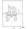
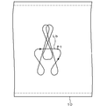
- FIG. 5 is a plan view of a continuous pattern of yarn material formed on the peripheral surface of the rotary carrier.
- FIG. 6 is an explanatory view of a threading track with respect to the peripheral surface of the rotary carrier.
- FIG. 7 is an explanatory diagram of the threading trajectory with respect to the fixed coordinates.
- FIG. 8 is an explanatory view of a seal portion.
- FIG. 9 is a plan view of the extraction bag sheet.
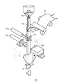
- FIG. 10 is a perspective view of the filling and packaging machine.
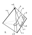
- FIG. 11 is a perspective view of the extraction bag.
- FIG. 1 is a configuration diagram of an embodiment of a tag supply device 20 that performs the tag supply method of the present invention
- FIG. 2 is a configuration diagram of an extraction bag sheet manufacturing machine 1 incorporating the tag supply device 20. is there.
- the extraction bag sheet manufacturing machine 1 generally includes a tag supply device 20 according to this embodiment for supplying a tag 2 to a peripheral surface of a rotary carrier 10 rotating in the direction of an arrow at a predetermined interval, a yarn hooking mechanism 40, and a rotary carrier.
- the extraction bag sheet 5 manufactured by the extraction bag sheet manufacturing machine 1 is used to make a bag in a pyramid shape, and the contents such as tea leaves are contained therein.
- a filling and packaging machine 70 for filling the product to produce the extraction bag 6 is provided downstream of the extraction bag sheet manufacturing machine 1.
- the tag supply device 20 includes a tag cut supply device 21 and a tag delivery drum 22.
- the tag cut supply device 21 intermittently feeds the tag tape 2t fed out from the tag tape raw material 2r to a so-called guillotine cutter 211 by a tag pitch feed driving roller 210 controlled by a motor and a nip roller facing the tag tape feed roller 210.
- the tag 2 is cut into a predetermined length, and the cut tag 2 is projected from the cutter 211 to the tag delivery drum 22 rotating at a constant speed in the direction of the arrow, and supplied to the tag delivery drum 22 at predetermined intervals.
- the tag delivery drum 22 sucks and holds the tag 2 supplied from the tag cut supply device 21 on its surface, and transfers it to the peripheral surface of the rotary carrier 10. Note that a mechanism for sucking and holding the tag 2 by switching the suction path by a rotary bubble is provided on the peripheral surface of the rotary carrier 10.
- the cutter 211 is held by the frame 212 of the tag cut supply device 21 so as to be slidable in the radial direction of the tag delivery drum 22.
- the frame 212 can swing around the rotation axis P1 of the tag delivery drum 22. Therefore, the cutter 211 can move along the circumferential surface of the tag delivery drum 22 while the tag 2 is cut from the tag tape 2t and the cut tag 2 is supplied to the tag delivery drum 22. Therefore, it becomes possible to smoothly deliver the cut tag 2 from the cutter 211 to the tag delivery drum 22.
- Such movement of the cutter 211 can be formed by the following crank and cam mechanism. That is, the frame 212 of the tag cut supply device 21 can swing around the rotation axis P ⁇ b> 1 of the tag delivery drum 22.
- an arm 220 is fixed to a tag cut supply device swing drive crankshaft P2 rotatably attached to the body of the extraction bag sheet manufacturing machine 1, and a rod 221 is connected to the other end.
- the end portion is rotatably joined to the frame 212 of the tag cut supply device by a joining portion 213.
- An arm 222 driven by a cam 230 is also fixed to the tag cut supply device swing drive crankshaft P2.
- a cutter drive crankshaft P3 is rotatably attached to the body of the extraction bag sheet manufacturing machine 1, one end of an arm 240 is fixed to the cutter drive crankshaft P3, and a rod 241 is connected to the other end.
- the end portion of the rod 241 is rotatably joined to the base material of the cutter 211 by the joining portion 214.
- An arm 242 driven by a cam 231 is also fixed to the cutter drive crankshaft P3.
- these cams 230 and 231 are integrally formed, and both rotate in the direction of the arrow b around a shaft P4 rotatably attached to the main body of the extraction bag sheet manufacturing machine 1. Therefore, the tag cut supply device swing drive crankshaft P2 is rotated by the follow of the arm 222 accompanying the rotation of the cam 230, and the arm 220 fixed to the shaft P2 swings around the shaft P2, thereby the rod A joint portion 213 between 221 and the frame 212 swings about the axis P1.
- the cutter drive crankshaft P3 is rotated by the follower of the arm 242 accompanying the rotation of the cam 231, and the arm 240 fixed to the shaft P3 swings around the axis P3, whereby the cutter 211 is moved to the tag delivery drum. 22 in the radial direction. In this way, the cutter 211 can take the locus of the arrow a.
- the rotation speed of the driving roller 253 for feeding the tag tape 2t is controlled by the servo motor 255 based on the angle detector 254 attached to the arm fulcrum shaft of the dancer roller 251.
- the path length adjusting link mechanism 260 is such that a rotatable joint 265 between the ends of the two bar links 262 and 264 is a fulcrum shaft of the guide roller 266 of the tag tape 2t.
- the other end of one bar link 262 has a fulcrum shaft 261 on the frame 212, and this fulcrum shaft 261 is also a fulcrum shaft of the guide roller.
- the other end of the other bar link 264 has a fulcrum shaft 263 on the mounting base of the frame 212 (the main body of the extraction bag sheet manufacturing machine 1).
- the tension associated with intermittent feeding of the tag tape 2t to the cutter 211 is set by appropriately setting the lengths of the bar links 262 and 264 and the positions of the fulcrum shafts 261 and 263.
- the fluctuation can be remarkably reduced, and the position fluctuation of the dancer roller 251 of the dancer mechanism 250 can be remarkably suppressed.
- the path length adjustment link mechanism 260 is not provided, and the center of the guide roller 266 is fixed to the main body of the extraction bag sheet manufacturing machine 1 as shown in FIG.
- the guide rollers 266 and 267 are arranged as shown in FIG. 3A when the variation amount of the position of the dancer roller 251 is about 70 mm.
- (C) is provided with a path length adjustment link mechanism 260, the length of the bar link 262 is 110 mm, the length of the bar link 264 is 60 mm, the diameter of the guide rollers 266 and 267 is 25 mm, and
- the fluctuation amount of the dancer roller 251 is about 5 mm.
- the dancer roller 251 The fluctuation amount can be reduced to about 17 mm.
- the rotation carrier 10 is continuously rotated in the direction of the arrow by a servo motor while the manufacturing machine 1 is in operation (FIG. 2).
- the outer periphery of the rotary carrier 10 is divided into 24 parts, and two placement parts for the tag 2 are provided close to each divided area.
- the suction of the tag 2 is started from the position facing the tag supply device 20, and the tag 2 and the water-permeable filter sheet 4 are weakly sealed as described later (fourth seal).
- the vacuum pump or blower motor sucks and holds the tag 2 by switching the suction path using the rotary bubble so that the suction is cut from the device 64) until before the extraction bag sheet is separated from the peripheral surface of the rotary carrier 10.
- a mechanism is provided.
- the rotary carrier 10 is provided with a vertical mechanism for the pin 11 for thread hooking.
- the pin 11 is always urged by a spring so as to protrude from the peripheral surface of the rotary carrier, but in the region where the water-permeable filter sheet 4 is supplied to the peripheral surface of the rotary carrier 10. Then, it is lowered toward the inside of the rotary carrier along the shape of the fixed cam provided inside the rotary carrier 10 so that the amount of protrusion from the peripheral surface of the pin 11 is small.
- the yarn hooking mechanism 40 forms a continuous rotation pattern of the thread material 3 on the peripheral surface of the rotary carrier 10 in which the tags 2 are arranged at predetermined intervals while adjusting the tension of the thread material 3 to be substantially constant.
- the tension adjusting means 410 includes a dancer mechanism 420 and a path length adjusting device 430 downstream thereof.
- the yarn hooking device 30 includes a first drive crank mechanism 32 a and a second drive crank mechanism 32 b connected in a substantially orthogonal direction by a joint portion 31.
- These drive crank mechanisms 32a and 32b include crank arms 34a and 34b driven by servo motors 33Ma and 33Mb, respectively, and links 35a and 35b connected to the crank arms 34a and 34b.
- the first drive crank mechanism 32a and The joint portion 31 of the second drive crank mechanism 32b connects the intermediate portion of the link of the first drive crank mechanism 32a and the tip portion of the link of the second drive crank mechanism 32b.
- a threading holding bracket 38 provided with a ring-shaped thread guide 36 and a threading 37 is provided at the tip of the link 35a of the first drive crank mechanism 32a.
- the joint portion 31 of the first drive crank mechanism 32a and the second drive crank mechanism 32b is provided at the intermediate portion of the link of the first drive crank mechanism 32a, the joint portion 31 and the crank arm 34b are linked. It is possible to prevent the sliding portion serving as a dust generation source such as a joint portion with 35b from being positioned on the peripheral surface of the rotation carrier 10. Further, since the threading holding bracket 38 is only positioned on the peripheral surface of the rotary carrier 10 and the link is located outside the peripheral surface, the thread-passing sheet or the water-permeable filterable sheet is placed on the rotary carrier 10. It is possible to eliminate as much as possible any obstacles during supply.
- the threading holding bracket 38 is driven by the two drive crank mechanisms 32a and 32b, and the servo motors 33Ma and 33Mb are used as the drive sources of the drive crank mechanisms 32a and 32b, respectively. Therefore, it is possible to move the threader 37 on the track required for threading.
- the threading pins 11 a and 11 b are connected to the tags 2.
- the rotation carrier 10 is protruded to a position near one peripheral edge 10 a and at a position away from each tag 2 in the axial direction of the rotation carrier 10.
- the thread hooking pins 11c and 11d are protruded, and the threading 37 at the tip of the threading holding bracket 38 has a predetermined radius (for example, 6 to 10 mm) around these pins 11 (11a, 11b, 11c and 11d). ), 11 and 1 It should be moved a threading device 30 as during the travel on the tangent of the above-mentioned circular orbit. 5 and 6, the broken line indicates the water-permeable filter sheet 4 to be supplied to the peripheral surface of the rotary carrier 10 later, and the dotted line indicates the region of one extraction bag in the water-permeable filter sheet 4. Indicates a separator. Further, in FIG. 6, the continuous rotation pattern of the thin line corresponds to the continuous rotation pattern of FIG.
- the trajectory La in FIG. 6 is a trajectory with respect to the pin 11 moving in the direction of the arrow due to the rotation of the rotary carrier 10, so that the threading 37 is fixed to the trajectory Lb shown in FIG.
- the threading device 30 is moved so as to draw
- symbol P1 in FIG. 6 and FIG. 7 has shown the corresponding point on these track
- Such movement of the threader 37 can be obtained by causing the servo motors 33Ma and 33Mb to reciprocate and controlling the rotation speed and rotation time thereof.
- the range of the swing angles ⁇ a, ⁇ b of the crank arms 34a, 34b is preferably set to 120 degrees or less.
- the crank arms 34a and 34b are close to the top dead center or the bottom dead center, the movement of the links 35a and 35b becomes smaller than the movement of the crank arms 34a and 34b, and the threader 37 can be moved at an intended speed.
- the threader 37 can be moved at an intended speed.
- the traveling speed of the threading 37 is controlled to be constant, and (ii) the threading 37 is around the pin 11.
- the speed of the threading 37 is controlled based on a predetermined deformation curve.
- Acceleration and deceleration of the threading 37 are performed based on a predetermined deformation curve.
- a mode in which the feeding speed of the thread material 3 from the thread material original fabric 3r around which the thread material 3 is wound can be set at a constant speed can be taken. To (iv).
- the sheet supply device 50 unwinds the water-permeable filterable sheet 4 from the sheet raw material 4r around which the water-permeable filterable sheet 4 is wound, and the water-permeable filterable sheet 4 is supported on the rotation carrier 10 at a predetermined interval. It supplies so that it may place on the continuous pattern of the tag 2 and the thread material 3 formed on the tag 2.
- the water-filterable sheet 4 can be fed out by controlling the feed-out speed with the nip drive roller 52 that feeds the water-filterable sheet 4 with an angle detector attached to the dancer roller 51 in the middle of the path. It is adjusted as fast as possible.
- the sealing device 60 before supplying the water-permeable filterable sheet 4 onto the rotation carrier 10, the tag 2 and the thread material 3 carried on the rotation carrier 10 are sealed as shown in FIG.
- the tag 2 After supplying the water-permeable filterable sheet 4 onto the first sealing device 61 and the rotary carrier 10 that are strongly sealed at s1, as shown in FIG. 8 (b), in the region for each extraction bag, the tag 2, a second sealing device 62 that strongly seals the thread material 3 and the water-permeable filter sheet 4 at a portion s2 that is separated in the longitudinal direction of the water-filterable sheet 4 from the tag 2 as shown in FIG.
- a fourth sealing device 64 for sealing the strong seal means that the seal part is firmly sealed to the extent that the seal part does not peel off when the normal extraction bag is used, and the weak seal means that the seal part is easily peeled off when the extraction bag is used. To seal as weakly as possible. Further, in the figure, hatching frames surrounding the seal portions s1, s2, s3, and s4 indicate regions where the seal head is applied.
- the seal part can be appropriately changed according to the rotation pattern of the thread material 3, the arrangement of the pins 11, and the like.
- the strong seal portion s2 between the thread material 3 and the water-permeable filter sheet 4 is equivalent to one extraction bag from the boundary region of one extraction bag as shown by s2 'shown by a broken line in FIG. You may shift to the center side of an area
- the thread material 3 and the water-permeable filterable sheet 4 at the seal portion s2 before bag making, the thread that becomes a hanging thread on the water-permeable filterable sheet 4 constituting the bag body in the extraction bag. This is preferable because the material 3 can be securely bonded.
- the sealing means in these sealing devices 60 may be ultrasonic welding or heat welding.
- ultrasonic welding is advantageous in that the sheet melt does not adhere to the sealing device. preferable.
- these sealing devices 60 are preferably moved up and down with respect to the peripheral surface of the rotation carrier 10 by using a servo motor as a drive source separately from the drive source of the rotation carrier 10. It is preferable to make it swing as shown by the arrow shown in FIG. As a result, the contact time between the seal head of the sealing device 60 and the tag, the thread material or the water-permeable filterable sheet that is the object to be sealed becomes longer, so that optimum sealing conditions can be easily set. Appropriate sealing conditions can be set even when the material is changed.
- the tag tape original fabric 2r, the yarn material original fabric 3r, and the sheet original fabric 4r are respectively set in the present machine. Then, the tag supply device 20 feeds the tag tape 2t from the tag tape original fabric 2r, cuts it into the tag 2, and carries the tag 2 on the peripheral surface of the rotary carrier 10 at a predetermined interval.
- the yarn hooking pin 11 is protruded from the peripheral surface of the rotary carrier 10, and the yarn material 3 is fed out from the yarn material original fabric 3 r by the yarn hooking device 30, and the yarn material 3 is fed to the peripheral surface of the rotary carrier 10. Is threaded into the continuous pattern shown in FIG.
- the first seal device 61 strongly seals the tag 2 and the thread material 3 as shown in FIG. 8A, and the sheet supply device 50 passes the tag 2 and the thread material 3 on the rotation carrier 10 over the tag 2 and the thread material 3.
- a water-filterable sheet 4 is supplied.
- the pin 11 protruding from the peripheral surface of the rotary carrier 10 when threading is pulled down when the water-permeable filter sheet 4 is supplied, and is passed when the tag 2 or the thread material 3 and the water-filterable sheet 4 are sealed. It prevents wrinkles from forming on the water filterable sheet 4.
- the second sealing device 62 strongly seals the thread material 3 and the water-permeable filter sheet 4 as shown in FIG. 8B, and the third sealing device 63 as shown in FIG. 8C.
- the thread material 3 and the water-permeable filter sheet 4 are weakly sealed, and the tag 2 and the water-filterable sheet 4 are weakly sealed by the fourth sealing device 64 as shown in FIG.
- the extraction bag sheet 5 shown in FIG. 9 can be obtained on the rotary carrier 10.
- s1 is a strong seal part between the tag 2 and the thread material 3
- s2 is a strong seal part between the thread material 3 and the water filterable sheet 4
- s3 is a weak seal between the thread material 3 and the water filterable sheet 4.
- the part, s4, is a weak seal part between the tag 2 and the water-permeable filterable sheet 4.
- the extraction bag sheet 5 may be wound up in a roll shape and subjected to a separate filling and packaging machine to be used for manufacturing an extraction bag.
- the extraction bag 6 may be manufactured by sending it to the filling and packaging machine 70.
- the filling and packaging machine 70 is operated in accordance with the speed of the extraction bag sheet 5 fed out by the reference feed roller 71 having a servo motor.
- a vertical sealing device 75 that seals a tube and a horizontal sealing device 76 that seals the extraction bag sheet 5 formed into a cylindrical shape in the width direction can be used.
- the horizontal sealing device 76 swings an attachment base (not shown) of the seal head 76a by 90 ° in a plane perpendicular to the longitudinal direction of the cylindrical body 73, and the seal head 76a is moved every time the swing base 76 is swung.
- welding and cutting in the width direction of the extraction bag sheet 5 are sequentially performed. Accordingly, for example, from the extraction bag sheet 5 in FIG. 9, as in the extraction bag 6 shown in FIG. 11, the widthwise seals sx and sy at the upper and lower edges of the pyramid type extraction bag are twisted positions.
- one end of the hanging thread made of the thread material 3 and the water-permeable filter sheet 4 are strongly sealed at the seal part s2 in the vicinity of the top, and the hanging thread at the part s1 at the other end of the hanging thread. It is possible to obtain an extraction bag in which the tag 2 is strongly sealed and the hanging thread and the tag 2 are weakly sealed with the water-permeable filter sheet 4 at the portions s3 and s4, respectively.
- the seal head 76a and its receiving 76b are moved downward so that the traveling of the extraction bag sheet 5 is not stopped. Is preferred. In this case, the seal head 76a and the receptacle 76b of the lateral seal device 76 are rotated 90 ° from the lowest position and returned to the upper position. Therefore, it is preferable to move the horizontal sealing device 76 repeatedly as shown by the arrows in FIG.
- sealing means of the vertical sealing device 75 and the horizontal sealing device 76 may be ultrasonic or may be heated.
- a first horizontal sealing device and a second horizontal sealing device having a sealing direction different by 90 ° are provided in a plane perpendicular to the longitudinal direction of the cylindrical body 73, and these are used alternately. You may make it do.
- scrap winding means 77 is provided for winding the edge portions. May be.
- the tag supply device 20 of the present invention can be used in various extraction bag sheet manufacturing machines. For example, it can be used to supply a tag for producing a flat bag-shaped extraction bag.
- the thread material 3 the tag tape 2t, and the water-permeable filterable sheet 4 used in the tag supply device 20 and the extraction bag sheet manufacturing machine 1 of the present invention
- conventional ones can be used.
- the thread material 3 one formed from a material capable of ultrasonic welding or heat welding including thermoplastic synthetic fibers such as polypropylene and polyethylene can be used.
- the tag tape 2t paper, What was formed from the plastic sheet etc. can be used.
- the water-permeable filter sheet 4 synthetic fibers such as polyester, nylon, polyethylene, and polypropylene, semi-synthetic fibers such as rayon, woven fabrics, nonwoven fabrics, papers made of natural fibers such as mulberry, Mitsumata, etc.
- a film having many holes can be used.
- the yarn hooking device and extraction bag sheet manufacturing machine of the present invention are useful for continuously manufacturing tea bags for tea, green tea, herbs, etc., boiled and dried bonito extract bags on the production line. .
Landscapes
- Engineering & Computer Science (AREA)
- Mechanical Engineering (AREA)
- Making Paper Articles (AREA)
Abstract
Selon l'invention, une bande d'étiquettes (2t) acheminée à partir d'une toile originale de bande d'étiquettes (2r) est découpée au moyen d'une coupeuse (211) pour former une étiquette (2) de longueur déterminée. L'étiquette (2) découpée est acheminée vers un tambour de transfert d'étiquettes rotatif (22) à partir de la coupeuse (211), selon un intervalle déterminé, et elle est déplacée du tambour (22) à une face périphérique d'un support rotatif (10). Ce dernier (10) est conçu pour soutenir l'étiquette (2) selon l'intervalle déterminé. La coupeuse (211) est maintenue coulissante par un bâti (212) oscillant, l'axe de rotation du tambour de transfert (22) servant de centre. Les fluctuations de force de traction de la bande d'étiquettes (2t) entre la toile originale (2r) et la coupeuse (211) sont supprimées par un mécanisme danseur (250) et un mécanisme de liaison réglant la longueur de trajet (260). Pour acheminer vers le support rotatif l'étiquette obtenue par découpe de la bande d'étiquettes au moyen de la coupeuse et fabriquer une feuille de sac d'extraction, les fluctuations de la force de traction de la bande d'étiquettes (2t) avec une transmission intermittente de l'étiquette à la coupeuse sont réduites et la vitesse d'acheminement d'étiquettes vers le support rotatif est accrue.
Priority Applications (1)
| Application Number | Priority Date | Filing Date | Title |
|---|---|---|---|
| PCT/JP2008/059254 WO2009141869A1 (fr) | 2008-05-20 | 2008-05-20 | Procede et dispositif d’acheminement d’etiquettes |
Applications Claiming Priority (1)
| Application Number | Priority Date | Filing Date | Title |
|---|---|---|---|
| PCT/JP2008/059254 WO2009141869A1 (fr) | 2008-05-20 | 2008-05-20 | Procede et dispositif d’acheminement d’etiquettes |
Publications (1)
| Publication Number | Publication Date |
|---|---|
| WO2009141869A1 true WO2009141869A1 (fr) | 2009-11-26 |
Family
ID=41339844
Family Applications (1)
| Application Number | Title | Priority Date | Filing Date |
|---|---|---|---|
| PCT/JP2008/059254 Ceased WO2009141869A1 (fr) | 2008-05-20 | 2008-05-20 | Procede et dispositif d’acheminement d’etiquettes |
Country Status (1)
| Country | Link |
|---|---|
| WO (1) | WO2009141869A1 (fr) |
Cited By (1)
| Publication number | Priority date | Publication date | Assignee | Title |
|---|---|---|---|---|
| EP2583911A4 (fr) * | 2010-06-17 | 2013-11-20 | Fuso Industry Co Ltd | Sachet d'extraction et feuille de matériau d'emballage |
Citations (4)
| Publication number | Priority date | Publication date | Assignee | Title |
|---|---|---|---|---|
| US5511359A (en) * | 1991-02-14 | 1996-04-30 | A.G. (Patents) Limited | Method and apparatus for making tagged infusion packages |
| JPH08318495A (ja) * | 1995-05-20 | 1996-12-03 | Koenig & Bauer Albert Ag | 切断装置 |
| JPH10157710A (ja) * | 1996-11-27 | 1998-06-16 | Fuso Sangyo Kk | 包 材 |
| JP2006510550A (ja) * | 2002-12-18 | 2006-03-30 | イ.エンメ.ア.インドゥストリア マッキーネ アウトマティケ ソチエタ ペル アツィオニ | 煎出製品用のフィルタバッグを作製する機械装置および方法 |
-
2008
- 2008-05-20 WO PCT/JP2008/059254 patent/WO2009141869A1/fr not_active Ceased
Patent Citations (4)
| Publication number | Priority date | Publication date | Assignee | Title |
|---|---|---|---|---|
| US5511359A (en) * | 1991-02-14 | 1996-04-30 | A.G. (Patents) Limited | Method and apparatus for making tagged infusion packages |
| JPH08318495A (ja) * | 1995-05-20 | 1996-12-03 | Koenig & Bauer Albert Ag | 切断装置 |
| JPH10157710A (ja) * | 1996-11-27 | 1998-06-16 | Fuso Sangyo Kk | 包 材 |
| JP2006510550A (ja) * | 2002-12-18 | 2006-03-30 | イ.エンメ.ア.インドゥストリア マッキーネ アウトマティケ ソチエタ ペル アツィオニ | 煎出製品用のフィルタバッグを作製する機械装置および方法 |
Cited By (1)
| Publication number | Priority date | Publication date | Assignee | Title |
|---|---|---|---|---|
| EP2583911A4 (fr) * | 2010-06-17 | 2013-11-20 | Fuso Industry Co Ltd | Sachet d'extraction et feuille de matériau d'emballage |
Similar Documents
| Publication | Publication Date | Title |
|---|---|---|
| JP5257631B2 (ja) | 抽出バッグ用シートの製造方法及び製造機械 | |
| WO2007046136A1 (fr) | Dispositif d'acheminement de film et dispositif de production d'emballage equipe de ce dernier | |
| JP5850268B2 (ja) | 抽出バッグ用シート製造装置 | |
| WO2009141871A1 (fr) | Procede de production de sac d’extraction | |
| CN102862319A (zh) | 双工位全自动塑料编织袋切缝机 | |
| JP5397381B2 (ja) | 抽出バッグ用シートの製造方法及び製造機械 | |
| WO2009141868A1 (fr) | Procede de filetage | |
| WO2009141869A1 (fr) | Procede et dispositif d’acheminement d’etiquettes | |
| WO2009141867A1 (fr) | Procede de filetage | |
| JP6667198B2 (ja) | 製袋包装機における帯状包装材供給装置 | |
| JP2019001466A (ja) | 包装機における紙継ぎ補助装置 | |
| KR101851922B1 (ko) | 단실 재봉 테이핑형 포대 재봉장치 | |
| CN107139513A (zh) | 一种橡筋机 | |
| CN203439307U (zh) | 包装机 | |
| JP2007111861A (ja) | ジッパー片供給装置 | |
| RU2575753C2 (ru) | Устройство для обрезания нитяного материала | |
| EP4317039B1 (fr) | Procédé et dispositif pour la fabrication d'article à porter | |
| JP2005231204A (ja) | 製袋機 | |
| WO2011061846A1 (fr) | Procédé de production de sac d'extraction | |
| JP2022119109A (ja) | 製袋包装機 | |
| JP2021195142A (ja) | 製袋器および包装機 | |
| JP2007131316A (ja) | 包装機 | |
| JP2002302104A (ja) | 包装充填機 | |
| JP2013501639A (ja) | 筒形ラベルの半完成品を製造するための方法および装置 |
Legal Events
| Date | Code | Title | Description |
|---|---|---|---|
| 121 | Ep: the epo has been informed by wipo that ep was designated in this application |
Ref document number: 08753000 Country of ref document: EP Kind code of ref document: A1 |
|
| NENP | Non-entry into the national phase |
Ref country code: DE |
|
| 122 | Ep: pct application non-entry in european phase |
Ref document number: 08753000 Country of ref document: EP Kind code of ref document: A1 |
|
| NENP | Non-entry into the national phase |
Ref country code: JP |