WO2009141870A1 - 抽出バッグ用シートの製造方法及び製造機械 - Google Patents
抽出バッグ用シートの製造方法及び製造機械 Download PDFInfo
- Publication number
- WO2009141870A1 WO2009141870A1 PCT/JP2008/059255 JP2008059255W WO2009141870A1 WO 2009141870 A1 WO2009141870 A1 WO 2009141870A1 JP 2008059255 W JP2008059255 W JP 2008059255W WO 2009141870 A1 WO2009141870 A1 WO 2009141870A1
- Authority
- WO
- WIPO (PCT)
- Prior art keywords
- sheet
- tag
- water
- thread material
- carrier
- Prior art date
- Legal status (The legal status is an assumption and is not a legal conclusion. Google has not performed a legal analysis and makes no representation as to the accuracy of the status listed.)
- Ceased
Links
Images



Classifications
-
- B—PERFORMING OPERATIONS; TRANSPORTING
- B65—CONVEYING; PACKING; STORING; HANDLING THIN OR FILAMENTARY MATERIAL
- B65B—MACHINES, APPARATUS OR DEVICES FOR, OR METHODS OF, PACKAGING ARTICLES OR MATERIALS; UNPACKING
- B65B29/00—Packaging of materials presenting special problems
- B65B29/02—Packaging of substances, e.g. tea, which are intended to be infused in the package
- B65B29/04—Attaching, or forming and attaching, string handles or tags to tea bags
-
- B—PERFORMING OPERATIONS; TRANSPORTING
- B29—WORKING OF PLASTICS; WORKING OF SUBSTANCES IN A PLASTIC STATE IN GENERAL
- B29C—SHAPING OR JOINING OF PLASTICS; SHAPING OF MATERIAL IN A PLASTIC STATE, NOT OTHERWISE PROVIDED FOR; AFTER-TREATMENT OF THE SHAPED PRODUCTS, e.g. REPAIRING
- B29C66/00—General aspects of processes or apparatus for joining preformed parts
- B29C66/01—General aspects dealing with the joint area or with the area to be joined
- B29C66/05—Particular design of joint configurations
- B29C66/10—Particular design of joint configurations particular design of the joint cross-sections
- B29C66/11—Joint cross-sections comprising a single joint-segment, i.e. one of the parts to be joined comprising a single joint-segment in the joint cross-section
- B29C66/112—Single lapped joints
- B29C66/1122—Single lap to lap joints, i.e. overlap joints
-
- B—PERFORMING OPERATIONS; TRANSPORTING
- B29—WORKING OF PLASTICS; WORKING OF SUBSTANCES IN A PLASTIC STATE IN GENERAL
- B29C—SHAPING OR JOINING OF PLASTICS; SHAPING OF MATERIAL IN A PLASTIC STATE, NOT OTHERWISE PROVIDED FOR; AFTER-TREATMENT OF THE SHAPED PRODUCTS, e.g. REPAIRING
- B29C66/00—General aspects of processes or apparatus for joining preformed parts
- B29C66/40—General aspects of joining substantially flat articles, e.g. plates, sheets or web-like materials; Making flat seams in tubular or hollow articles; Joining single elements to substantially flat surfaces
- B29C66/41—Joining substantially flat articles ; Making flat seams in tubular or hollow articles
- B29C66/43—Joining a relatively small portion of the surface of said articles
- B29C66/431—Joining the articles to themselves
- B29C66/4312—Joining the articles to themselves for making flat seams in tubular or hollow articles, e.g. transversal seams
-
- B—PERFORMING OPERATIONS; TRANSPORTING
- B65—CONVEYING; PACKING; STORING; HANDLING THIN OR FILAMENTARY MATERIAL
- B65B—MACHINES, APPARATUS OR DEVICES FOR, OR METHODS OF, PACKAGING ARTICLES OR MATERIALS; UNPACKING
- B65B37/00—Supplying or feeding fluent-solid, plastic, or liquid material, or loose masses of small articles, to be packaged
- B65B37/08—Supplying or feeding fluent-solid, plastic, or liquid material, or loose masses of small articles, to be packaged by rotary feeders
- B65B37/10—Supplying or feeding fluent-solid, plastic, or liquid material, or loose masses of small articles, to be packaged by rotary feeders of screw type
-
- B—PERFORMING OPERATIONS; TRANSPORTING
- B65—CONVEYING; PACKING; STORING; HANDLING THIN OR FILAMENTARY MATERIAL
- B65B—MACHINES, APPARATUS OR DEVICES FOR, OR METHODS OF, PACKAGING ARTICLES OR MATERIALS; UNPACKING
- B65B51/00—Devices for, or methods of, sealing or securing package folds or closures; Devices for gathering or twisting wrappers, or necks of bags
- B65B51/10—Applying or generating heat or pressure or combinations thereof
- B65B51/22—Applying or generating heat or pressure or combinations thereof by friction or ultrasonic or high-frequency electrical means
- B65B51/225—Applying or generating heat or pressure or combinations thereof by friction or ultrasonic or high-frequency electrical means by ultrasonic welding
-
- B—PERFORMING OPERATIONS; TRANSPORTING
- B65—CONVEYING; PACKING; STORING; HANDLING THIN OR FILAMENTARY MATERIAL
- B65B—MACHINES, APPARATUS OR DEVICES FOR, OR METHODS OF, PACKAGING ARTICLES OR MATERIALS; UNPACKING
- B65B51/00—Devices for, or methods of, sealing or securing package folds or closures; Devices for gathering or twisting wrappers, or necks of bags
- B65B51/10—Applying or generating heat or pressure or combinations thereof
- B65B51/26—Devices specially adapted for producing transverse or longitudinal seams in webs or tubes
- B65B51/30—Devices, e.g. jaws, for applying pressure and heat, e.g. for subdividing filled tubes
-
- B—PERFORMING OPERATIONS; TRANSPORTING
- B65—CONVEYING; PACKING; STORING; HANDLING THIN OR FILAMENTARY MATERIAL
- B65B—MACHINES, APPARATUS OR DEVICES FOR, OR METHODS OF, PACKAGING ARTICLES OR MATERIALS; UNPACKING
- B65B9/00—Enclosing successive articles, or quantities of material, e.g. liquids or semiliquids, in flat, folded, or tubular webs of flexible sheet material; Subdividing filled flexible tubes to form packages
- B65B9/10—Enclosing successive articles, or quantities of material, in preformed tubular webs, or in webs formed into tubes around filling nozzles, e.g. extruded tubular webs
- B65B9/20—Enclosing successive articles, or quantities of material, in preformed tubular webs, or in webs formed into tubes around filling nozzles, e.g. extruded tubular webs the webs being formed into tubes in situ around the filling nozzles
- B65B9/213—Enclosing successive articles, or quantities of material, in preformed tubular webs, or in webs formed into tubes around filling nozzles, e.g. extruded tubular webs the webs being formed into tubes in situ around the filling nozzles the web having intermittent motion
-
- B—PERFORMING OPERATIONS; TRANSPORTING
- B29—WORKING OF PLASTICS; WORKING OF SUBSTANCES IN A PLASTIC STATE IN GENERAL
- B29C—SHAPING OR JOINING OF PLASTICS; SHAPING OF MATERIAL IN A PLASTIC STATE, NOT OTHERWISE PROVIDED FOR; AFTER-TREATMENT OF THE SHAPED PRODUCTS, e.g. REPAIRING
- B29C65/00—Joining or sealing of preformed parts, e.g. welding of plastics materials; Apparatus therefor
- B29C65/02—Joining or sealing of preformed parts, e.g. welding of plastics materials; Apparatus therefor by heating, with or without pressure
- B29C65/08—Joining or sealing of preformed parts, e.g. welding of plastics materials; Apparatus therefor by heating, with or without pressure using ultrasonic vibrations
-
- B—PERFORMING OPERATIONS; TRANSPORTING
- B29—WORKING OF PLASTICS; WORKING OF SUBSTANCES IN A PLASTIC STATE IN GENERAL
- B29C—SHAPING OR JOINING OF PLASTICS; SHAPING OF MATERIAL IN A PLASTIC STATE, NOT OTHERWISE PROVIDED FOR; AFTER-TREATMENT OF THE SHAPED PRODUCTS, e.g. REPAIRING
- B29C65/00—Joining or sealing of preformed parts, e.g. welding of plastics materials; Apparatus therefor
- B29C65/02—Joining or sealing of preformed parts, e.g. welding of plastics materials; Apparatus therefor by heating, with or without pressure
- B29C65/18—Joining or sealing of preformed parts, e.g. welding of plastics materials; Apparatus therefor by heating, with or without pressure using heated tools
-
- B—PERFORMING OPERATIONS; TRANSPORTING
- B29—WORKING OF PLASTICS; WORKING OF SUBSTANCES IN A PLASTIC STATE IN GENERAL
- B29C—SHAPING OR JOINING OF PLASTICS; SHAPING OF MATERIAL IN A PLASTIC STATE, NOT OTHERWISE PROVIDED FOR; AFTER-TREATMENT OF THE SHAPED PRODUCTS, e.g. REPAIRING
- B29C66/00—General aspects of processes or apparatus for joining preformed parts
- B29C66/70—General aspects of processes or apparatus for joining preformed parts characterised by the composition, physical properties or the structure of the material of the parts to be joined; Joining with non-plastics material
- B29C66/71—General aspects of processes or apparatus for joining preformed parts characterised by the composition, physical properties or the structure of the material of the parts to be joined; Joining with non-plastics material characterised by the composition of the plastics material of the parts to be joined
-
- B—PERFORMING OPERATIONS; TRANSPORTING
- B29—WORKING OF PLASTICS; WORKING OF SUBSTANCES IN A PLASTIC STATE IN GENERAL
- B29L—INDEXING SCHEME ASSOCIATED WITH SUBCLASS B29C, RELATING TO PARTICULAR ARTICLES
- B29L2031/00—Other particular articles
- B29L2031/712—Containers; Packaging elements or accessories, Packages
- B29L2031/7122—Tea bags
-
- B—PERFORMING OPERATIONS; TRANSPORTING
- B65—CONVEYING; PACKING; STORING; HANDLING THIN OR FILAMENTARY MATERIAL
- B65B—MACHINES, APPARATUS OR DEVICES FOR, OR METHODS OF, PACKAGING ARTICLES OR MATERIALS; UNPACKING
- B65B9/00—Enclosing successive articles, or quantities of material, e.g. liquids or semiliquids, in flat, folded, or tubular webs of flexible sheet material; Subdividing filled flexible tubes to form packages
- B65B9/10—Enclosing successive articles, or quantities of material, in preformed tubular webs, or in webs formed into tubes around filling nozzles, e.g. extruded tubular webs
- B65B9/20—Enclosing successive articles, or quantities of material, in preformed tubular webs, or in webs formed into tubes around filling nozzles, e.g. extruded tubular webs the webs being formed into tubes in situ around the filling nozzles
- B65B9/2056—Machines for packages of special type or form
Definitions
- the present invention relates to a yarn hooking device used for manufacturing a sheet for an extraction bag and a machine for manufacturing a sheet for an extraction bag using the yarn hooking device.
- a water-permeable filterable sheet such as non-woven fabric is formed into a flat bag shape, tetrahedron shape bag body, etc. What is used is filled with extraction materials such as tea leaves and attached with a hanging thread with a tag on the outer surface.
- Patent Document 1 As a sheet for an extraction bag used for manufacturing such an extraction bag, one in which a hanging thread with a tag for one extraction bag is arranged at a predetermined interval in the longitudinal direction of a belt-like water-permeable filterable sheet is known.
- Patent Document 2 As to enable the extraction bag sheet to be manufactured with higher productivity, the tags are arranged in the longitudinal direction of the sheet at predetermined intervals on the belt-like water-permeable filterable sheet, A long thread material arranged in a specific rotation pattern so as to be placed on each tag is known (Patent Document 2). JP 10-157709 A JP 2006-510550 A
- Manufactures extraction bag sheets by arranging tags on a belt-shaped water-permeable filterable sheet at predetermined intervals in the longitudinal direction of the sheet, and by arranging a long thread material in a specific rotation pattern so as to hang on each tag
- a tag is supported on a rotating carrier at predetermined intervals, and a long thread material is placed on the tag in a specific rotation pattern so as to hang on each tag.
- there is a sealing step in which the water-permeable filterable sheet is supplied onto the rotation carrier, and the thread material or tag and the water-filterable sheet are bonded on the rotation carrier.
- Patent Document 2 a plurality of sealing devices used in these sealing steps are moved up and down with respect to the circumferential surface of the rotating carrier by a cam mechanism using a common driving source with the rotating carrier. .
- an object of the present invention is to allow a tag, a thread material, and a water-permeable filterable sheet to be bonded under optimum conditions in accordance with the production speed of those materials and extraction bag sheets. .
- the inventor of the present invention provides a sealing device for bonding a tag and a thread material on a rotating carrier, preferably a sealing device for bonding a thread material and a water-permeable filter sheet in addition to the sealing device, and a tag and a water flow.
- the seal device for adhering the filterable sheet is moved up and down with respect to the peripheral surface of the rotation carrier, and is swung in accordance with the rotation of the rotation carrier, and the vertical movement and the vibration are respectively controlled by a servo motor. It has been found that the above-mentioned object can be achieved by controlling the above.
- the present invention is a method for manufacturing a sheet for an extraction bag in which tags bonded to a thread material are arranged at predetermined intervals in the longitudinal direction of a water-permeable filterable sheet, (1) A step of carrying the tag at a predetermined interval on the rotary carrier (2) Threading step of forming a continuous pattern of thread material by rotating the threader on the peripheral surface of the rotating carrier from which the threading pin protrudes (3) Sealing process for bonding the thread and tag (4) A step of supplying a water-permeable filterable sheet onto the tag and the thread material on the rotating carrier.
- Sealing process for bonding the thread material and the water-permeable filterable sheet on the rotating carrier (6) It has a sealing process for bonding the tag and the water-permeable filterable sheet on the rotating carrier, and in the sealing processes of (3), (5) and (6), the shaft is swung around the axis of the rotating carrier.
- the seal head that moves and moves up and down relative to the peripheral surface of the rotating carrier is used, and the rocking speed, vertical movement speed and pressure contact time of the seal head are controlled by the rocking servo motor and the vertical movement servo motor.
- a method for producing a sheet for an extraction bag is provided.
- the present invention provides an extraction bag sheet in which tags bonded to a thread material are arranged at predetermined intervals in the longitudinal direction of a water-permeable filter sheet as a machine for carrying out the above-described method for producing an extraction bag sheet.
- a manufacturing machine The tag bonded to the thread material is a machine for manufacturing a sheet for an extraction bag in which the tags are arranged at predetermined intervals in the longitudinal direction of the water-permeable filterable sheet, (1) Tag supply device for supporting a tag on a rotating carrier at predetermined intervals (2) A yarn hooking device that forms a continuous pattern of yarn material by rotating the threader on the peripheral surface of the rotating carrier from which the yarn hooking pins protrude.
- Sealing device for bonding the thread material and tag Sheet supply means for supplying a water-permeable filterable sheet onto the tag and thread material on the rotating carrier (5) Sealing device for bonding the thread material and the water-permeable filterable sheet on the rotating carrier (6) It has a sealing device that adheres the tag and the water-permeable filterable sheet on the rotating carrier, and the sealing devices of (3), (5) and (6) swing around the axis of the rotating carrier. It has a seal head that moves and moves up and down with respect to the peripheral surface of the rotary carrier, and that the seal head swing speed, vertical motion speed and pressure contact time can be controlled by the swing servo motor and the vertical motion servo motor.
- a machine for manufacturing a sheet for an extraction bag Provided is a machine for manufacturing a sheet for an extraction bag.
- a sealing device for bonding a tag and a thread material on a rotating carrier preferably, in addition to this, a thread material and a water-permeable filterable sheet And a seal device for adhering the tag and the water filterable sheet are moved up and down with respect to the peripheral surface of the rotary carrier, and swung in accordance with the rotation of the rotary carrier, and The vertical movement and swinging are controlled by a servo motor.
- the timing can be adjusted arbitrarily, so that a predetermined seal strength can be obtained while the sealing device is moved in the rotational direction of the rotating carrier in both cases of ultrasonic sealing and heat sealing.
- the sealing device can be brought into pressure contact with the circumferential surface of the rotating carrier only for the time required to remove the pressure, and when returning the sealing device in the opposite direction to the rotation of the rotating carrier, the production speed of the extraction bag sheet is changed. It can be moved at high speed.
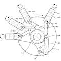
- FIG. 1A is a rear view of the sealing device of the embodiment.
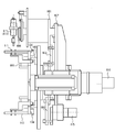
- FIG. 1B is a cross-sectional view of the sealing device of the embodiment.
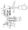
- FIG. 1C is a cross-sectional view of the sealing device of the embodiment.
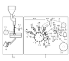
- FIG. 2 is a schematic configuration diagram of an extraction bag sheet manufacturing machine according to an embodiment.
- FIG. 3 is a perspective view (a) and a top view (b) of the yarn hooking device.
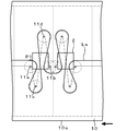
- FIG. 4 is a plan view of a continuous pattern of yarn material formed on the peripheral surface of the rotary carrier.
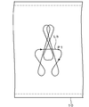
- FIG. 5 is an explanatory view of a threading track with respect to the peripheral surface of the rotary carrier.
- FIG. 6 is an explanatory diagram of the threading trajectory with respect to the fixed coordinates.
- FIG. 7 is an explanatory view of a seal portion.
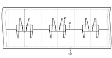
- FIG. 8 is a plan view of the extraction bag sheet.
- FIG. 9 is a perspective view of the filling and packaging machine.
- FIG. 10 is a perspective
- FIG. 1A is a rear view of an embodiment of a sealing device 60 used in the present invention
- FIG. 1B is a vertical sectional view thereof
- FIG. 1C is a horizontal sectional view thereof
- FIG. It is a block diagram of the manufacturing machine 1 of the sheet
- the extraction bag sheet manufacturing machine 1 generally includes a tag supply device 20 for supplying a tag 2 to the peripheral surface of the rotation carrier 10 at predetermined intervals, a thread hooking mechanism 40, the tag 2 on the rotation carrier 10 and a yarn material. 3, a sheet supply device 50 for supplying the water-permeable filterable sheet 4, the adhesion between the tag 2 and the thread material 3, the adhesion between the tag 2 and the water-permeable filter sheet 4, or the thread material 3 and the water-permeable filterability. It consists of a sealing device 60 for bonding with the sheet 4.
- the extraction bag sheet 5 manufactured by the extraction bag sheet manufacturing machine 1 is used to make a bag in a pyramid shape, and the contents such as tea leaves are contained therein.
- a filling and packaging machine 70 for filling the product to produce the extraction bag 6 is provided downstream of the extraction bag sheet manufacturing machine 1.
- the rotary carrier 10 is driven by the rotary carrier servomotor 12 through the gears 13a, 13b, 13c, and 13d during the operation of the manufacturing machine 1 (FIG. 1C), FIG. It is designed to rotate continuously in the direction of the arrow.
- the outer periphery of the rotary carrier 10 is divided into 24 parts, and two placement parts for the tag 2 are provided close to each divided area.
- the suction of the tag 2 is started from the position facing the tag supply device 20, and the tag 2 and the water-permeable filter sheet 4 are weakly sealed as described later (fourth seal).
- the tag 2 is sucked and carried by a vacuum pump or a blower motor by switching the suction path using a rotary bubble so that the suction is cut from the device 64) until before the extraction bag sheet is separated from the peripheral surface of the rotary carrier 10.
- a mechanism is provided.
- the rotary carrier 10 is provided with a vertical mechanism for the pin 11 for thread hooking.
- the pin 11 is always urged by the spring 101 so as to protrude from the peripheral surface of the rotary carrier, but the region where the water-permeable filter sheet 4 is supplied to the peripheral surface of the rotary carrier 10 Then, it is lowered toward the inside of the rotary carrier along the shape of the fixed cam 102 provided inside the rotary carrier 10 so that the amount of protrusion from the peripheral surface of the pin 11 becomes small.
- the tag supply device 20 feeds the tag tape 2t from the tag tape original fabric 2r around which the tab tape 2t is wound, and cuts the tag tape 2t into a tag 2 having a predetermined length, and the tag cut supply device 21 cuts the tag tape 2t.
- the tag delivery drum 22 moves the tag 2 to the peripheral surface of the rotary carrier 10.
- the tag cut supply device 21 is provided with a cam mechanism so that the tag 2 can be supplied as fast as possible without loosening the tag tape 2t from the tag tape original fabric 2r to the rotary carrier 10.
- the tag tape 2t is cut while being swung as indicated by an arrow, and the cut tag 2 is transferred to the tag transfer drum 22.
- the tag delivery drum 22 rotates at a constant speed, and the tag 2 delivered from the tag cut supply device 21 is carried on the rotation carrier 10 at a predetermined interval.
- the yarn hooking mechanism 40 adjusts the tension of the yarn material 3 to be substantially constant, while the yarn material 3 that overlaps each tag 2 at least at one place on the circumferential surface of the rotary carrier 10 in which the tags 2 are arranged at predetermined intervals.
- a continuous rotation pattern is formed, and a driving roller 401 for feeding the yarn material 3 from the yarn material web 3r, a nip roller 402 facing the drive roller 401, a tension adjusting means 410 for the yarn material 3, and a circumferential surface of the rotary carrier 10 are formed.
- the yarn hooking device 30 for forming a continuous rotation pattern of the yarn material 3 is provided, and the tension adjusting means 410 includes a dancer mechanism 420 and a path length adjusting device 430 downstream thereof.
- the yarn hooking device 30 includes a first drive crank mechanism 32 a and a second drive crank mechanism 32 b connected in a substantially orthogonal direction by a joint portion 31.
- These drive crank mechanisms 32a and 32b include crank arms 34a and 34b driven by servo motors 33Ma and 33Mb, respectively, and links 35a and 35b connected to the crank arms 34a and 34b.
- the first drive crank mechanism 32a and The joint portion 31 of the second drive crank mechanism 32b connects the intermediate portion of the link 35a of the first drive crank mechanism 32a and the tip portion of the link 35b of the second drive crank mechanism 32b.
- a threading holding bracket 38 provided with a ring-shaped thread guide 36 and a threading 37 is provided at the tip of the link 35a of the first drive crank mechanism 32a.
- the joint portion 31 of the first drive crank mechanism 32a and the second drive crank mechanism 32b is provided in the middle portion of the link 35a of the first drive crank mechanism 32a, the joint portion 31 and the crank arm 34b It is possible to prevent the sliding portion serving as a dust generation source such as a joint portion with the link 35b from being positioned on the peripheral surface of the rotation carrier 10. Further, since the threading holding bracket 38 is only positioned on the peripheral surface of the rotary carrier 10 and the link is located outside the peripheral surface, the thread-passing sheet or the water-permeable filterable sheet is placed on the rotary carrier 10. It is possible to eliminate as much as possible any obstacles during supply.
- the threading holding bracket 38 is driven by the two drive crank mechanisms 32a and 32b, and the servo motors 33Ma and 33Mb are used as the drive sources of the drive mechanism cranks 32a and 32b, respectively. Therefore, it is possible to move the threader 37 on the track required for threading.
- the threading pins 11 a and 11 b are connected to the tags 2.
- the rotation carrier 10 is protruded to a position near one peripheral edge 10 a and at a position away from each tag 2 in the axial direction of the rotation carrier 10.
- the thread hooking pins 11c and 11d are protruded, and the threading 37 at the tip of the threading holding bracket 38 has a predetermined radius (for example, 6 to 10 mm) around these pins 11 (11a, 11b, 11c and 11d). ), 11 and 1 It should be moved a threading device 30 as during the travel on the tangent of the above-mentioned circular orbit. 4 and 5, the broken line indicates the water-permeable filter sheet 4 to be supplied to the peripheral surface of the rotary carrier 10 later, and the dotted line indicates the region of one extraction bag in the water-permeable filter sheet 4. Indicates a separator. Further, in FIG. 5, the continuous rotation pattern of the thin line corresponds to the continuous rotation pattern of FIG.
- the trajectory La in FIG. 5 is a trajectory with respect to the pin 11 moving in the direction of the arrow due to the rotation of the rotary carrier 10, so that the threading 37 is fixed to the trajectory Lb shown in FIG.
- the threading device 30 is moved so as to draw
- symbol P1 in FIG. 5 and FIG. 6 has shown the corresponding point on these track
- Such movement of the threader 37 can be obtained by causing the servo motors 33Ma and 33Mb to reciprocate and controlling the rotation speed and rotation time thereof.
- the range of the swing angles ⁇ a, ⁇ b of the crank arms 34a, 34b is preferably set to 120 degrees or less.
- the crank arms 34a and 34b are close to the top dead center or the bottom dead center, the movement of the links 35a and 35b becomes smaller than the movement of the crank arms 34a and 34b, and the threader 37 can be moved at an intended speed.
- the threader 37 can be moved at an intended speed.
- the traveling speed of the threading 37 is controlled to be constant, and (ii) the threading 37 is around the pin 11.
- the speed of the threading 37 is controlled based on a predetermined deformation curve.
- Acceleration and deceleration of the threading 37 are performed based on a predetermined deformation curve.
- a mode in which the feeding speed of the thread material 3 from the thread material original fabric 3r around which the thread material 3 is wound can be set at a constant speed can be taken. To (iv).
- the sheet supply device 50 unwinds the water-permeable filterable sheet 4 from the sheet raw material 4r around which the water-permeable filterable sheet 4 is wound, and the water-permeable filterable sheet 4 is supported on the rotation carrier 10 at a predetermined interval. It supplies so that it may place on the continuous pattern of the tag 2 and the thread material 3 formed on the tag 2.
- the water-filterable sheet 4 can be fed out by controlling the feed-out speed with the nip drive roller 52 that feeds the water-filterable sheet 4 with an angle detector attached to the dancer roller 51 in the middle of the path. Adjust as fast as possible.
- the sealing device 60 includes first, second, third, and fourth sealing devices 61, 62, 63, and 64 that are driven by a control mechanism characteristic of the present invention. That is, before supplying the water-permeable filterable sheet 4 onto the rotation carrier 10, the tag 2 and the thread material 3 carried on the rotation carrier 10 are strongly sealed at the seal portion s1 shown in FIG. After supplying the water-permeable filterable sheet 4 onto the first sealing device 61 and the rotary carrier 10, the water is passed from the tag 2 in the area for each extraction bag as shown in FIG. 7B. A second sealing device 62 that strongly seals the thread material 3 and the water-permeable filterable sheet 4 at a site s2 that is separated in the longitudinal direction of the filterable sheet 4, as shown in FIG.
- a third sealing device 63 that weakly seals the thread material 3 and the water-permeable filter sheet 4 at the portion s3 where the thread material 3 is extended in the width direction of the water-filterable sheet 4.
- a fourth seal that weakly seals the tag 2 and the water-permeable filter sheet 4 at the seal part s4 shown in (d).
- a le device 64 the strong seal means that the seal part is firmly sealed to the extent that the seal part does not peel off when the normal extraction bag is used, and the weak seal means that the seal part is easily peeled off when the extraction bag is used. To seal as weakly as possible.
- hatching frames surrounding the seal portions s1, s2, s3, and s4 indicate regions where the seal head is applied.
- the seal part can be appropriately changed according to the rotation pattern of the thread material 3, the arrangement of the pins 11, and the like.
- the strong seal portion s2 between the thread material 3 and the water-permeable filter sheet 4 is equivalent to one extraction bag from the boundary region of one extraction bag as shown by s2 'shown by a broken line in FIG. You may shift to the center side of an area
- the thread material 3 and the water-permeable filterable sheet 4 at the seal portion s2 before bag making, the thread that becomes a hanging thread on the water-permeable filterable sheet 4 constituting the bag body in the extraction bag. This is preferable because the material 3 can be securely bonded.
- the sealing means in these sealing devices 60 may be ultrasonic welding or heat welding.
- ultrasonic welding is advantageous in that the sheet melt does not adhere to the sealing device. preferable.
- a vertical driving servo motor 65 is provided separately from the driving source of the rotary carrier 10.
- the rotary carrier 10 is moved up and down with respect to the peripheral surface of the rotary carrier 10 and reciprocally rocked in the rotation direction of the rotary carrier 10 using the oscillation servo motor 66 as a drive source, as shown by the arrows in FIG. 1A. Rock.
- a seal head mounting plate 601 for fixing the seal devices 61, 62, 63, 64 is mounted on the swing plate 602 so as to be slidable in the radial direction of the rotary carrier 10, and each seal head is mounted.
- the plate 601 is connected to the vertical movement plate 604 by the bar link 603, and the vertical movement plate 604 is further connected to the seal head vertical drive servomotor 65 provided in the vicinity of the drive shaft of the rotation carrier 10 by the bar link 605.
- each of the sealing devices 61, 62, 63, 64 is fixed to the seal head mounting plate 601 via an air cylinder 606.
- the pressing pressure to the peripheral surface of the rotary carrier 10 at the lowered position of the seal head is determined.
- the head is retracted from the peripheral surface of the rotary carrier 10 so that the seal head and the rotary carrier 10 are not wasted.
- the vertical movement plate 604 has the same axis of rotation as the rotation carrier 10, but the rotation carrier 10 is driven by the rotation carrier servo motor 12 disposed in the vicinity of the tag cut supply device 21.
- the vertical movement plate 604 is driven by the seal head vertical drive servomotor 65 separately from the rotary carrier 10.
- the swing plate 602 has the same rotation axis as that of the rotary carrier 10, but is driven by a seal head swing servo motor 66 separately from the rotary carrier 10.
- the drive control of the seal head vertical movement servo motor 65 and the seal head swing servo motor 66 is calculated in advance according to the rotation pattern of the yarn material 3, the rotation speed of the rotary carrier 10, the required pressure contact time, and the like. It is controlled by the controller so as to take a predetermined rotation speed and rotation direction at the determined timing.
- the vertical movement speed, the pressure contact start timing and the pressure release timing can be adjusted.
- the speed can be adjusted. This makes it possible to adjust the press-contact time between the seal head of the seal device 60 and the tag, thread material or water-permeable filterable sheet that is the object to be sealed, and is optimal even when these materials are changed.
- Sealing conditions can be set easily. In this case, the setting of the oscillation output of the ultrasonic seal and the heating temperature of the heat seal may be changed, but without changing these, the press contact time of the seal device 60 is increased by the servo motor 65 for vertical driving and the servo motor 66 for oscillation. By adjusting, it becomes possible to easily optimize the sealing conditions.
- the tag tape original fabric 2r, the yarn material original fabric 3r, and the sheet original fabric 4r are respectively set in the present machine. Then, the tag supply device 20 feeds the tag tape 2t from the tag tape original fabric 2r, cuts it into the tag 2, and carries the tag 2 on the peripheral surface of the rotary carrier 10 at a predetermined interval.
- the yarn hooking pin 11 is protruded from the peripheral surface of the rotary carrier 10, and the yarn material 3 is fed out from the yarn material original fabric 3 r by the yarn hooking device 30, and the yarn material 3 is fed to the peripheral surface of the rotary carrier 10. Is threaded into the continuous pattern shown in FIG.
- the first seal device 61 strongly seals the tag 2 and the thread material 3 as shown in FIG. 7A, and the sheet supply device 50 passes the tag 2 and the thread material 3 on the rotary carrier 10 over the tag 2 and the thread material 3.
- a water-filterable sheet 4 is supplied.
- the pin 11 protruding from the peripheral surface of the rotary carrier 10 when threading is pulled down when the water-permeable filter sheet 4 is supplied, and is passed when the tag 2 or the thread material 3 and the water-filterable sheet 4 are sealed. It prevents wrinkles from forming on the water filterable sheet 4.
- the thread material 3 and the water-permeable filter sheet 4 are strongly sealed by the second sealing device 62 as shown in FIG. 7B, and the third sealing device 63 is used as shown in FIG. 7C.
- the thread material 3 and the water-permeable filter sheet 4 are weakly sealed, and the tag 2 and the water-filterable sheet 4 are weakly sealed by the fourth sealing device 64 as shown in FIG.
- the extraction bag sheet 5 shown in FIG. 8 can be obtained on the rotary carrier 10.
- s1 is a strong seal part between the tag 2 and the thread material 3
- s2 is a strong seal part between the thread material 3 and the water filterable sheet 4
- s3 is a weak seal between the thread material 3 and the water filterable sheet 4.
- the part, s4, is a weak seal part between the tag 2 and the water-permeable filterable sheet 4.
- the extraction bag sheet 5 may be wound up in a roll shape and subjected to a separate filling and packaging machine to be used for manufacturing an extraction bag.
- the extraction bag 6 may be manufactured by sending it to the filling and packaging machine 70.
- the filling and packaging machine 70 is operated in accordance with the speed of the extraction bag sheet 5 fed out by the reference feed roller 71 having a servo motor.
- a vertical sealing device 75 that seals a tube and a horizontal sealing device 76 that seals the extraction bag sheet 5 formed into a cylindrical shape in the width direction can be used.
- the horizontal sealing device 76 swings an attachment base (not shown) of the seal head 76a by 90 ° in a plane perpendicular to the longitudinal direction of the cylindrical body 73, and the seal head 76a is moved every time the swing base 76 is swung.
- welding and cutting in the width direction of the extraction bag sheet 5 are sequentially performed.
- the widthwise seals sx, sy at the upper and lower end edges of the pyramid type extraction bag are twisted positions.
- one end of the hanging thread made of the thread material 3 and the water-permeable filter sheet 4 are strongly sealed at the seal part s2 in the vicinity of the top, and the hanging thread at the part s1 at the other end of the hanging thread. It is possible to obtain an extraction bag in which the tag 2 is strongly sealed and the hanging thread and the tag 2 are weakly sealed with the water-permeable filter sheet 4 at the portions s3 and s4, respectively.
- the seal head 76a and its receiving 76b are moved downward so that the traveling of the extraction bag sheet 5 is not stopped. Is preferred. In this case, the seal head 76a and the receptacle 76b of the lateral seal device 76 are rotated 90 ° from the lowest position and returned to the upper position. Therefore, it is preferable to move the horizontal sealing device 76 repeatedly as shown by the arrows in FIG.
- sealing means of the vertical sealing device 75 and the horizontal sealing device 76 may be ultrasonic or may be heated.
- a first horizontal sealing device and a second horizontal sealing device having a sealing direction different by 90 ° are provided in a plane perpendicular to the longitudinal direction of the cylindrical body 73, and these are used alternately. You may make it do.
- scrap winding means 77 is provided for winding the edge portions. May be.
- the thread material 3 the tag tape 2t, and the water-permeable filterable sheet 4 used in the extraction bag sheet manufacturing machine 1 of the present invention
- conventional ones can be used.
- the thread material 3 one formed from a material capable of ultrasonic welding or heat welding including thermoplastic synthetic fibers such as polypropylene and polyethylene can be used.
- the tag tape 2t paper, What was formed from the plastic sheet etc. can be used.
- the water-permeable filter sheet 4 synthetic fibers such as polyester, nylon, polyethylene, and polypropylene, semi-synthetic fibers such as rayon, woven fabrics, nonwoven fabrics, papers made of natural fibers such as mulberry, Mitsumata, etc.
- a film having many holes can be used.
- the machine for producing a sheet for an extraction bag of the present invention is useful for continuously producing tea bags such as black tea, green tea and herbs, and extraction bags for dried stock such as dried and dried bonito on a production line.
Landscapes
- Engineering & Computer Science (AREA)
- Mechanical Engineering (AREA)
- Packages (AREA)
- Making Paper Articles (AREA)
Abstract
Description
(1)回転担持体にタグを所定間隔で担持させる工程
(2)糸掛用ピンが突出した回転担持体の周面で、糸通しを回旋させることにより糸材の連続的パターンを形成する糸掛工程
(3)糸材とタグを接着するシール工程
(4)回転担持体上のタグと糸材の上に通水濾過性シートを供給する工程
(5)回転担持体上で糸材と通水濾過性シートを接着するシール工程
(6)回転担持体上でタグと通水濾過性シートを接着するシール工程
を有し、(3)、(5)及び(6)のシール工程において、回転担持体の軸心を中心に揺動すると共に回転担持体の周面に対して上下動するシールヘッドを使用し、シールヘッドの揺動速度、上下動速度及び圧接時間を揺動用サーボモータと上下動用サーボモータで制御することを特徴とする抽出バッグ用シートの製造方法を提供する。
糸材と接着したタグが、通水濾過性シートの長手方向に所定間隔で配列している抽出バッグ用シートの製造機械であって、
(1)回転担持体にタグを所定間隔で担持させるタグ供給装置
(2)糸掛用ピンが突出した回転担持体の周面で、糸通しを回旋させることにより糸材の連続的パターンを形成する糸掛装置
(3)糸材とタグを接着するシール装置
(4)回転担持体上のタグと糸材の上に通水濾過性シートを供給するシート供給手段
(5)回転担持体上で糸材と通水濾過性シートを接着するシール装置
(6)回転担持体上でタグと通水濾過性シートを接着するシール装置
を有し、(3)、(5)及び(6)のシール装置が、回転担持体の軸心を中心に揺動すると共に回転担持体の周面に対して上下動するシールヘッドを備え、シールヘッドの揺動速度、上下動速度及び圧接時間が揺動用サーボモータと上下動用サーボモータで制御可能であることを特徴とする抽出バッグ用シートの製造機械を提供する。
2 タグ
2r タグテープ原反
2t タグテープ
3 糸材
3r 糸材原反
4 通水濾過性シート
4r シート原反
5 抽出バッグ用シート
6 抽出バッグ
10 回転担持体
101 スプリング
102 固定カム
11、11a、11b、11c、11d ピン
12 回転担持体用サーボモータ
13a、13b、13c、13d ギア
20 タグ供給装置
21 タグカット供給装置
22 タグ受渡ドラム
30 糸掛装置
31 ジョイント部
32a 第1の駆動クランク機構
32b 第2の駆動クランク機構
33Ma、33Mb サーボモータ
34a、34b クランクアーム
35a、35b リンク
36 糸ガイド
37 糸通し
38 糸通し保持ブラケット
40 糸掛機構
401 駆動ローラ
402 ニップローラ
410 糸材の張力調整手段
420 ダンサー機構
422 サーボモータ
430 パス長調整装置
50 シート供給装置
51 ダンサーローラ
52 ニップ駆動ローラ
60 シール装置
61 第1のシール装置
62 第2のシール装置
63 第3のシール装置
64 第4のシール装置
65 シールヘッド上下駆動用サーボモータ
66 シールヘッド揺動用サーボモータ
601 シールヘッド取付プレート
602 揺動プレート
603 棒リンク
604 上下動プレート
605 棒リンク
606 エアシリンダ
70 充填包装機
71 基準送りローラ
72 フォーマーガイド
73 筒体
74 送りローラ
75 縦シール装置
76 横シール装置
76a シールヘッド
76b シールヘッドの受け
77 スクラップ巻き取り手段
80 オーガ充填機
La 糸通しのピンに対する軌道
La 固定座標における糸通しの軌道
P1 タグ受渡ドラムの回転軸
P2 タグカット供給装置揺動駆動クランク軸
P3 カッター駆動クランク軸
θa、θb クランクアームの揺動角
s1、s2、s3、s4 シール部位
Claims (2)
- 糸材と接着したタグが、通水濾過性シートの長手方向に所定間隔で配列している抽出バッグ用シートの製造方法であって、
(1)回転担持体にタグを所定間隔で担持させる工程
(2)糸掛用ピンが突出した回転担持体の周面で、糸通しを回旋させることにより糸材の連続的パターンを形成する糸掛工程
(3)糸材とタグを接着するシール工程
(4)回転担持体上のタグと糸材の上に通水濾過性シートを供給する工程
(5)回転担持体上で糸材と通水濾過性シートを接着するシール工程
(6)回転担持体上でタグと通水濾過性シートを接着するシール工程
を有し、(3)、(5)及び(6)のシール工程において、回転担持体の軸心を中心に揺動すると共に回転担持体の周面に対して上下動するシールヘッドを使用し、シールヘッドの揺動速度、上下動速度及び圧接時間を揺動用サーボモータと上下動用サーボモータで制御することを特徴とする抽出バッグ用シートの製造方法。 - 糸材と接着したタグが、通水濾過性シートの長手方向に所定間隔で配列している抽出バッグ用シートの製造機械であって、
(1)回転担持体にタグを所定間隔で担持させるタグ供給装置
(2)糸掛用ピンが突出した回転担持体の周面で、糸通しを回旋させることにより糸材の連続的パターンを形成する糸掛装置
(3)糸材とタグを接着するシール装置
(4)回転担持体上のタグと糸材の上に通水濾過性シートを供給するシート供給手段
(5)回転担持体上で糸材と通水濾過性シートを接着するシール装置
(6)回転担持体上でタグと通水濾過性シートを接着するシール装置
を有し、(3)、(5)及び(6)のシール装置が、回転担持体の軸心を中心に揺動すると共に回転担持体の周面に対して上下動するシールヘッドを備え、シールヘッドの揺動速度、上下動速度及び圧接時間が揺動用サーボモータと上下動用サーボモータで制御可能であることを特徴とする抽出バッグ用シートの製造機械。
Priority Applications (9)
| Application Number | Priority Date | Filing Date | Title |
|---|---|---|---|
| JP2010512877A JP5257631B2 (ja) | 2008-05-20 | 2008-05-20 | 抽出バッグ用シートの製造方法及び製造機械 |
| CN2008801293464A CN102036880B (zh) | 2008-05-20 | 2008-05-20 | 提取袋用薄片的制造方法及制造机械 |
| US12/920,365 US8500617B2 (en) | 2008-05-20 | 2008-05-20 | Method for manufacturing extraction bag sheet |
| EA201001040A EA018135B1 (ru) | 2008-05-20 | 2008-05-20 | Способ и установка для производства листового материала для экстракционных пакетиков |
| EP08753001.0A EP2301848B1 (en) | 2008-05-20 | 2008-05-20 | Manufacturing method and manufacturing machine of sheet for extraction bag |
| PCT/JP2008/059255 WO2009141870A1 (ja) | 2008-05-20 | 2008-05-20 | 抽出バッグ用シートの製造方法及び製造機械 |
| PL08753001T PL2301848T3 (pl) | 2008-05-20 | 2008-05-20 | Sposób wytwarzania i maszyna do wytwarzania arkusza na torebki do parzenia |
| KR1020107022427A KR101397852B1 (ko) | 2008-05-20 | 2008-05-20 | 추출백용 시트의 제조 방법 및 제조 기계 |
| ES08753001.0T ES2548919T3 (es) | 2008-05-20 | 2008-05-20 | Procedimiento y máquina de fabricación de hoja de bolsita de extracción |
Applications Claiming Priority (1)
| Application Number | Priority Date | Filing Date | Title |
|---|---|---|---|
| PCT/JP2008/059255 WO2009141870A1 (ja) | 2008-05-20 | 2008-05-20 | 抽出バッグ用シートの製造方法及び製造機械 |
Publications (1)
| Publication Number | Publication Date |
|---|---|
| WO2009141870A1 true WO2009141870A1 (ja) | 2009-11-26 |
Family
ID=41339845
Family Applications (1)
| Application Number | Title | Priority Date | Filing Date |
|---|---|---|---|
| PCT/JP2008/059255 Ceased WO2009141870A1 (ja) | 2008-05-20 | 2008-05-20 | 抽出バッグ用シートの製造方法及び製造機械 |
Country Status (9)
| Country | Link |
|---|---|
| US (1) | US8500617B2 (ja) |
| EP (1) | EP2301848B1 (ja) |
| JP (1) | JP5257631B2 (ja) |
| KR (1) | KR101397852B1 (ja) |
| CN (1) | CN102036880B (ja) |
| EA (1) | EA018135B1 (ja) |
| ES (1) | ES2548919T3 (ja) |
| PL (1) | PL2301848T3 (ja) |
| WO (1) | WO2009141870A1 (ja) |
Cited By (3)
| Publication number | Priority date | Publication date | Assignee | Title |
|---|---|---|---|---|
| CN102294844A (zh) * | 2011-09-19 | 2011-12-28 | 中华全国供销合作总社杭州茶叶研究院 | 一种塔型袋成型装置 |
| CN102431674A (zh) * | 2011-09-19 | 2012-05-02 | 中华全国供销合作总社杭州茶叶研究院 | 一种袋泡茶叶茶包机 |
| WO2013065118A1 (ja) | 2011-10-31 | 2013-05-10 | 大紀商事株式会社 | 糸材切断装置 |
Families Citing this family (16)
| Publication number | Priority date | Publication date | Assignee | Title |
|---|---|---|---|---|
| WO2012004169A2 (en) * | 2010-07-07 | 2012-01-12 | Unilever Plc | Process and apparatus for producing packets |
| US20130277887A1 (en) * | 2011-01-12 | 2013-10-24 | James Robert Stirling Howarth | Process for producing infusion packets |
| JP5001448B1 (ja) * | 2011-07-08 | 2012-08-15 | 株式会社 伊藤園 | 抽出バッグ |
| ES2481816T3 (es) * | 2011-12-22 | 2014-07-31 | Boato Pack S.R.L. A Socio Unico | Máquina de llenado |
| EP2626318B1 (de) * | 2012-02-10 | 2015-01-21 | Teepack Spezialmaschinen Gmbh & Co. Kg | Aufgussbeutel |
| ITBO20120706A1 (it) * | 2012-12-21 | 2014-06-22 | Ima Ind Srl | Macchina per la formazione di bustine con prodotti da infusione |
| ITUB20161017A1 (it) * | 2016-02-24 | 2017-08-24 | Ima Spa | Macchina per la formazione di sacchetti-filtro per prodotti da infusione. |
| WO2018106151A1 (ru) * | 2016-12-08 | 2018-06-14 | Елена Аркадьевна МЕРИНОВА | Устройство для производства заварочных сит |
| RU174361U1 (ru) * | 2016-12-08 | 2017-10-11 | Елена Аркадьевна Меринова | Устройство для производства заварочных сит |
| IT201700029640A1 (it) | 2017-03-17 | 2018-09-17 | Ima Spa | Macchina per la formazione di sacchetti - filtro per prodotti da infusione. |
| IT201800006476A1 (it) * | 2018-06-20 | 2019-12-20 | Macchina per la formazione di sacchetti filtro per prodotti da infusione | |
| WO2020237598A1 (zh) * | 2019-05-31 | 2020-12-03 | 凯迈(洛阳)机电有限公司 | 一种固定标签的滤袋成型包装机 |
| WO2020237599A1 (zh) * | 2019-05-31 | 2020-12-03 | 凯迈(洛阳)机电有限公司 | 一种多列滤袋成型包装机 |
| EP4079647B1 (de) * | 2021-04-23 | 2024-08-07 | Teepack Spezialmaschinen GmbH & Co. KG | Vorrichtung und verfahren zum transportieren von fertig zugeschnittenen und befüllten schlauchstücken |
| DE102022105805A1 (de) | 2022-03-11 | 2023-09-14 | Herrmann Ultraschalltechnik Gmbh & Co. Kg | Vorrichtung zur Ultraschallbearbeitung mit zwei Sonotroden sowie Verfahren mit einer solchen Vorrichtung |
| CN117183461B (zh) * | 2023-09-22 | 2025-10-31 | 瑞安市明国机械有限公司 | 高速纸杯贴把机 |
Citations (4)
| Publication number | Priority date | Publication date | Assignee | Title |
|---|---|---|---|---|
| JPH10157709A (ja) | 1996-11-27 | 1998-06-16 | Fuso Sangyo Kk | 包材の製造方法及び製造装置 |
| JPH1177860A (ja) * | 1997-07-17 | 1999-03-23 | Fab Toyama:Kk | パウチへのスパウト取付装置 |
| JP2004255742A (ja) * | 2003-02-26 | 2004-09-16 | Toyo Jidoki Co Ltd | スパウト挿入シール装置及び該装置を使用した製袋包装機 |
| JP2006510550A (ja) | 2002-12-18 | 2006-03-30 | イ.エンメ.ア.インドゥストリア マッキーネ アウトマティケ ソチエタ ペル アツィオニ | 煎出製品用のフィルタバッグを作製する機械装置および方法 |
Family Cites Families (14)
| Publication number | Priority date | Publication date | Assignee | Title |
|---|---|---|---|---|
| ES2044683T3 (es) * | 1990-03-21 | 1994-01-01 | Unilever Nv | Bolsas y procedimiento de empaquetado. |
| GB9026123D0 (en) * | 1990-11-30 | 1991-01-16 | Unilever Plc | Tagged articles and method and apparatus for their production |
| GB9103156D0 (en) * | 1991-02-14 | 1991-04-03 | Ag Patents Ltd | Manufacturing infusion packages |
| GB9219657D0 (en) * | 1992-09-17 | 1992-10-28 | Unilever Plc | Tagged articles |
| GB9422999D0 (en) * | 1994-11-15 | 1995-01-04 | Ag Patents Ltd | Method and apparatus for the manufacture of infusion packages |
| US5755923A (en) * | 1996-11-26 | 1998-05-26 | Owens-Corning Fiberglas Technology, Inc. | Heat seal apparatus |
| IT1309285B1 (it) * | 1999-06-08 | 2002-01-22 | Ima Spa | Macchina per la realizzazione di sacchetti - filtro di prodotti dainfusione. |
| EP1153834B1 (de) * | 2000-05-11 | 2003-09-10 | TEEPACK SPEZIALMASCHINEN GMBH & CO. KG | Verfahren zur kontinuierlichen herstellung von aufgussbeuteln |
| JP4527254B2 (ja) | 2000-08-08 | 2010-08-18 | 株式会社クレハ | 自動充填包装方法及び装置 |
| JP4382302B2 (ja) | 2001-05-02 | 2009-12-09 | 株式会社フジシールインターナショナル | シート送出装置 |
| ITBO20020477A1 (it) * | 2002-07-23 | 2004-01-23 | Tecnomeccanica Srl | Apparato di preparazione ed alimentazione di materiali per confezionamento di una busta filtro per sostanze da infusione. |
| JP4978124B2 (ja) | 2006-09-13 | 2012-07-18 | 大紀商事株式会社 | 抽出バッグ用シート |
| KR100846694B1 (ko) | 2008-02-05 | 2008-07-17 | 주식회사 폴리쉘 | 포장재 제조장치 및 그 제조방법 |
| EA017840B1 (ru) * | 2009-01-15 | 2013-03-29 | Цубакимото Когьо Ко., Лтд. | Пакетировочно-упаковочная машина и способ пакетирования и упаковки объекта |
-
2008
- 2008-05-20 US US12/920,365 patent/US8500617B2/en active Active
- 2008-05-20 WO PCT/JP2008/059255 patent/WO2009141870A1/ja not_active Ceased
- 2008-05-20 ES ES08753001.0T patent/ES2548919T3/es active Active
- 2008-05-20 EP EP08753001.0A patent/EP2301848B1/en active Active
- 2008-05-20 KR KR1020107022427A patent/KR101397852B1/ko active Active
- 2008-05-20 JP JP2010512877A patent/JP5257631B2/ja active Active
- 2008-05-20 CN CN2008801293464A patent/CN102036880B/zh active Active
- 2008-05-20 EA EA201001040A patent/EA018135B1/ru not_active IP Right Cessation
- 2008-05-20 PL PL08753001T patent/PL2301848T3/pl unknown
Patent Citations (4)
| Publication number | Priority date | Publication date | Assignee | Title |
|---|---|---|---|---|
| JPH10157709A (ja) | 1996-11-27 | 1998-06-16 | Fuso Sangyo Kk | 包材の製造方法及び製造装置 |
| JPH1177860A (ja) * | 1997-07-17 | 1999-03-23 | Fab Toyama:Kk | パウチへのスパウト取付装置 |
| JP2006510550A (ja) | 2002-12-18 | 2006-03-30 | イ.エンメ.ア.インドゥストリア マッキーネ アウトマティケ ソチエタ ペル アツィオニ | 煎出製品用のフィルタバッグを作製する機械装置および方法 |
| JP2004255742A (ja) * | 2003-02-26 | 2004-09-16 | Toyo Jidoki Co Ltd | スパウト挿入シール装置及び該装置を使用した製袋包装機 |
Non-Patent Citations (1)
| Title |
|---|
| See also references of EP2301848A4 |
Cited By (5)
| Publication number | Priority date | Publication date | Assignee | Title |
|---|---|---|---|---|
| CN102294844A (zh) * | 2011-09-19 | 2011-12-28 | 中华全国供销合作总社杭州茶叶研究院 | 一种塔型袋成型装置 |
| CN102431674A (zh) * | 2011-09-19 | 2012-05-02 | 中华全国供销合作总社杭州茶叶研究院 | 一种袋泡茶叶茶包机 |
| WO2013065118A1 (ja) | 2011-10-31 | 2013-05-10 | 大紀商事株式会社 | 糸材切断装置 |
| KR20140097139A (ko) | 2011-10-31 | 2014-08-06 | 오끼 쇼지 가부시키가이샤 | 실재 절단 장치 |
| US9650168B2 (en) | 2011-10-31 | 2017-05-16 | Ohki Co., Ltd. | Thread material cutting device |
Also Published As
| Publication number | Publication date |
|---|---|
| JPWO2009141870A1 (ja) | 2011-09-22 |
| EP2301848B1 (en) | 2015-07-08 |
| EP2301848A1 (en) | 2011-03-30 |
| EP2301848A4 (en) | 2014-02-26 |
| KR20110014138A (ko) | 2011-02-10 |
| PL2301848T3 (pl) | 2015-12-31 |
| KR101397852B1 (ko) | 2014-05-20 |
| US20110047937A1 (en) | 2011-03-03 |
| US8500617B2 (en) | 2013-08-06 |
| ES2548919T3 (es) | 2015-10-21 |
| JP5257631B2 (ja) | 2013-08-07 |
| EA201001040A1 (ru) | 2011-06-30 |
| EA018135B1 (ru) | 2013-05-30 |
| CN102036880A (zh) | 2011-04-27 |
| CN102036880B (zh) | 2012-08-15 |
Similar Documents
| Publication | Publication Date | Title |
|---|---|---|
| JP5257631B2 (ja) | 抽出バッグ用シートの製造方法及び製造機械 | |
| EP2774857B1 (en) | Thread material cutting device | |
| WO2009141871A1 (ja) | 抽出バッグの製造方法 | |
| US8904740B2 (en) | Method and apparatus for changing a strip of sealed bag precursors in to open bags | |
| JP5397381B2 (ja) | 抽出バッグ用シートの製造方法及び製造機械 | |
| KR101605625B1 (ko) | 디스플레이장치용 접착시트 제조장치 | |
| WO2009141868A1 (ja) | 糸掛方法 | |
| JP6667198B2 (ja) | 製袋包装機における帯状包装材供給装置 | |
| WO2009141867A1 (ja) | 糸掛方法 | |
| WO2009141869A1 (ja) | タグ供給方法及び供給装置 | |
| JP5240482B2 (ja) | 抽出バッグ用充填包装機 | |
| JP2008080802A (ja) | 製袋機及び袋の製造方法。 | |
| JP4454250B2 (ja) | ジッパーアプリケータ | |
| RU2575753C2 (ru) | Устройство для обрезания нитяного материала | |
| US4913015A (en) | Soft material cutting apparatus | |
| WO2011061846A1 (ja) | 抽出バッグの製造方法 | |
| JP6292086B2 (ja) | 抽出バッグ用シートの製造装置 | |
| JP2007111861A (ja) | ジッパー片供給装置 | |
| EP4317039B1 (en) | Method and device for manufacturing wearable article | |
| JP2008055739A (ja) | 包装用フィルムへの注出ノズルの取付け方法およびそれに用いる取付け装置 | |
| JP2005231204A (ja) | 製袋機 | |
| JP2017218171A (ja) | 製袋充填包装機 |
Legal Events
| Date | Code | Title | Description |
|---|---|---|---|
| WWE | Wipo information: entry into national phase |
Ref document number: 200880129346.4 Country of ref document: CN |
|
| 121 | Ep: the epo has been informed by wipo that ep was designated in this application |
Ref document number: 08753001 Country of ref document: EP Kind code of ref document: A1 |
|
| WWE | Wipo information: entry into national phase |
Ref document number: 201001040 Country of ref document: EA |
|
| WWE | Wipo information: entry into national phase |
Ref document number: 2010512877 Country of ref document: JP |
|
| WWE | Wipo information: entry into national phase |
Ref document number: 12920365 Country of ref document: US |
|
| WWE | Wipo information: entry into national phase |
Ref document number: 2008753001 Country of ref document: EP |
|
| ENP | Entry into the national phase |
Ref document number: 20107022427 Country of ref document: KR Kind code of ref document: A |
|
| NENP | Non-entry into the national phase |
Ref country code: DE |