WO2009144813A1 - 脱気用中空糸モジュールの製造方法 - Google Patents
脱気用中空糸モジュールの製造方法 Download PDFInfo
- Publication number
- WO2009144813A1 WO2009144813A1 PCT/JP2008/060020 JP2008060020W WO2009144813A1 WO 2009144813 A1 WO2009144813 A1 WO 2009144813A1 JP 2008060020 W JP2008060020 W JP 2008060020W WO 2009144813 A1 WO2009144813 A1 WO 2009144813A1
- Authority
- WO
- WIPO (PCT)
- Prior art keywords
- hollow fiber
- sheet
- resin
- degassing
- fiber module
- Prior art date
- Legal status (The legal status is an assumption and is not a legal conclusion. Google has not performed a legal analysis and makes no representation as to the accuracy of the status listed.)
- Ceased
Links
Images


Classifications
-
- B—PERFORMING OPERATIONS; TRANSPORTING
- B01—PHYSICAL OR CHEMICAL PROCESSES OR APPARATUS IN GENERAL
- B01D—SEPARATION
- B01D63/00—Apparatus in general for separation processes using semi-permeable membranes
- B01D63/02—Hollow fibre modules
- B01D63/021—Manufacturing thereof
-
- B—PERFORMING OPERATIONS; TRANSPORTING
- B01—PHYSICAL OR CHEMICAL PROCESSES OR APPARATUS IN GENERAL
- B01D—SEPARATION
- B01D19/00—Degasification of liquids
-
- B—PERFORMING OPERATIONS; TRANSPORTING
- B01—PHYSICAL OR CHEMICAL PROCESSES OR APPARATUS IN GENERAL
- B01D—SEPARATION
- B01D19/00—Degasification of liquids
- B01D19/0031—Degasification of liquids by filtration
-
- B—PERFORMING OPERATIONS; TRANSPORTING
- B01—PHYSICAL OR CHEMICAL PROCESSES OR APPARATUS IN GENERAL
- B01D—SEPARATION
- B01D63/00—Apparatus in general for separation processes using semi-permeable membranes
- B01D63/02—Hollow fibre modules
- B01D63/021—Manufacturing thereof
- B01D63/022—Encapsulating hollow fibres
- B01D63/0222—Encapsulating hollow fibres using centrifugal forces
-
- B—PERFORMING OPERATIONS; TRANSPORTING
- B01—PHYSICAL OR CHEMICAL PROCESSES OR APPARATUS IN GENERAL
- B01D—SEPARATION
- B01D63/00—Apparatus in general for separation processes using semi-permeable membranes
- B01D63/10—Spiral-wound membrane modules
- B01D63/101—Spiral winding
-
- B—PERFORMING OPERATIONS; TRANSPORTING
- B41—PRINTING; LINING MACHINES; TYPEWRITERS; STAMPS
- B41J—TYPEWRITERS; SELECTIVE PRINTING MECHANISMS, i.e. MECHANISMS PRINTING OTHERWISE THAN FROM A FORME; CORRECTION OF TYPOGRAPHICAL ERRORS
- B41J2/00—Typewriters or selective printing mechanisms characterised by the printing or marking process for which they are designed
- B41J2/005—Typewriters or selective printing mechanisms characterised by the printing or marking process for which they are designed characterised by bringing liquid or particles selectively into contact with a printing material
- B41J2/01—Ink jet
- B41J2/17—Ink jet characterised by ink handling
- B41J2/19—Ink jet characterised by ink handling for removing air bubbles
-
- B—PERFORMING OPERATIONS; TRANSPORTING
- B01—PHYSICAL OR CHEMICAL PROCESSES OR APPARATUS IN GENERAL
- B01D—SEPARATION
- B01D2313/00—Details relating to membrane modules or apparatus
- B01D2313/12—Specific discharge elements
Definitions
- the present invention relates to a method for producing a degassing hollow fiber module used for diaphragm-type degassing that removes gas or bubbles dissolved in a liquid through a side wall (membrane) of the hollow fiber.
- the degassing hollow fiber module manufactured according to the present invention includes, for example, deoxygenated water for boiler feedwater, superoxygenation such as deoxygenation, decarboxylation, and denitrification in the ultrapure water production process in the semiconductor production process, and lithography process. It can be used for resist degassing, developing solution degassing, red water degassing of buildings and condominiums, medical water degassing, jet ink degassing, and defoaming.
- a so-called external perfusion type in which a liquid is flowed in contact with the outside of the hollow fiber and the inside of the hollow fiber is depressurized contains dissolved gas. It is described that the removal performance is excellent.
- the inside of the hollow fiber is evacuated while supplying ink containing bubbles to the degassing hollow fiber module so as to touch the outside of the hollow fiber. Bubbles contained in the ink permeate the membrane due to the pressure difference between the inside and outside of the hollow fiber and are removed to the low pressure side. The ink from which bubbles are removed is discharged from the module without passing through the hollow fiber.
- Either method can be used for jet ink deaeration, but the external perfusion type is preferably used rather than the internal perfusion type in terms of the deaeration efficiency per membrane area and the pressure loss.
- the hollow fiber used in the present invention is a hollow fiber membrane that allows gas to permeate but does not allow liquid to permeate
- the material, membrane shape, and membrane form are arbitrary, and are conventionally used in deaeration hollow fiber modules.
- the hollow fiber material includes polyolefin resins such as polypropylene and poly (4-methylpentene-1), silicon resins such as polydimethylsiloxane and copolymers thereof, and fluorine resins such as PTFE and vinylidene fluoride. Can be mentioned.
- any of a porous membrane, a microporous membrane, and a homogeneous membrane having no porosity can be used.
- a symmetric film homogeneous film in which the chemical or physical structure of the entire film is homogeneous or an asymmetric film (heterogeneous film) in which the chemical or physical structure of the film varies depending on the part of the film is used. be able to.
- An asymmetric membrane is a membrane having a non-porous dense layer and a porous layer, but the dense layer is formed anywhere in the membrane, such as the surface layer portion of the membrane or inside the porous membrane. It doesn't matter.
- This heterogeneous film includes a so-called composite film having a different chemical structure and a multilayer structure film such as a three-layer structure.
- a heterogeneous film using poly (4-methylpentene-1) resin has a dense layer that blocks the liquid, and thus is particularly preferable for deaeration of liquids other than water, such as ink.
- a dense layer is formed on the outer surface of the hollow fiber.
- a conventional degassing hollow fiber module has, for example, a cylindrical core and a number of hollow fibers bundled around the core as disclosed in Patent Documents 6, 7, and 8 below.
- the cylindrical core ensures the rigidity of the degassing hollow fiber module and functions as a base for supporting a large number of hollow fibers when the module is manufactured. Furthermore, it also serves as a liquid supply channel for controlling the flow of liquid, but it also contributes to pressure loss.
- Japanese Patent Laid-Open No. 5-17712 Japanese Patent Laid-Open No. 10-298470 Japanese Patent Laid-Open No. 2-107317 JP-A-5-245347 JP-A-5-245348 JP-A-52-99978 JP 2002-361050 A JP 2005-305432 A
- the deaeration hollow fiber module needs to be as small as possible and have a small pressure loss, and the deaeration hollow fiber module tends to be downsized.
- the cylindrical core is provided with the function of retaining the rigidity of the hollow fiber module for deaeration and the support base of the hollow fiber. The pressure loss that occurs during the process is a major problem.
- the present invention has been made in view of the above circumstances, and is a degassing hollow fiber module for manufacturing a degassing hollow fiber module that greatly reduces pressure loss and meets the demand for miniaturization with high accuracy.
- An object is to provide a manufacturing method.
- the degassing hollow fiber module manufacturing method of the present invention includes a step of winding a sheet containing a number of hollow fibers around a temporary core, and a step of holding the sheet wound around the temporary core in a cylindrical shape. And a step of removing the temporary core from the sheet held in a cylindrical shape.
- a sheet containing a number of hollow fibers is wound around a temporary core and held in a cylindrical shape, and then the temporary core is removed from the cylindrically held sheet.
- FIG. 1 is a diagram showing an embodiment of a method for producing a degassing hollow fiber module according to the present invention, and is a cross-sectional view of the degassing hollow fiber module produced according to the present invention.
- FIG. 2 is an exploded cross-sectional view of the degassing hollow fiber module shown in FIG.
- FIG. 3 is an enlarged cross-sectional view of the lower end of the yarn bundle shown in FIG.
- FIG. 4 is an enlarged cross-sectional view of the upper end of the yarn bundle shown in FIG.
- FIG. 5 is an enlarged perspective view of a hollow fiber sheet that is the basis of the yarn bundle shown in FIG. 1.
- FIG. 6 is a schematic diagram for explaining the function of the degassing hollow fiber module shown in FIG. 1.
- FIG. 1 is a diagram showing an embodiment of a method for producing a degassing hollow fiber module according to the present invention, and is a cross-sectional view of the degassing hollow fiber module produced according to the present invention.
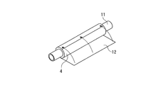
- FIG. 7 is a view showing an embodiment of a method for producing a hollow fiber module for degassing according to the present invention, and is a perspective view for explaining a winding process of a hollow fiber sheet around a resin tube.
- FIG. 8 is a view showing an embodiment of the method for producing the degassing hollow fiber module of the present invention, and is a perspective view for explaining a temporary fixing process of the hollow fiber sheet by the temporary fixing sheet.
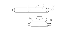
- FIG. 9 is a view showing an embodiment of the method for producing the degassing hollow fiber module of the present invention, and is a perspective view for explaining the cutting process of the original roll.
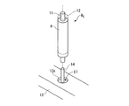
- FIG. 10 is a view showing an embodiment of the method for producing the degassing hollow fiber module of the present invention, and is a perspective view for explaining a stationary sealing step of one end of the yarn bundle.
- FIG. 11 is a perspective view for explaining a stationary sealing process at one end of the yarn bundle, as in FIG. 10.
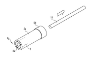
- FIG. 12 is a view showing an embodiment of the method for producing the degassing hollow fiber module of the present invention, and is a perspective view for explaining a step of removing the resin tube from the unit roll.
- FIG. 13 is a view showing an embodiment of the method for producing the degassing hollow fiber module of the present invention, and is a perspective view for explaining the centrifugal sealing process of the other end of the yarn bundle.
- FIG. 14 is a perspective view for explaining a centrifugal sealing process at the other end of the yarn bundle, as in FIG. 13.
- FIG. 15 is a diagram showing an embodiment of the method for producing the degassing hollow fiber module of the present invention, and is a perspective view for explaining a cutting process of the header from the housing body.
- FIG. 16 is a view showing Modification Example 1 of the method for producing the degassing hollow fiber module of the present invention, and is a perspective view for explaining a winding process of the hollow fiber sheet around the resin sheet.
- FIG. 17 is a view showing a second modification of the method for producing the degassing hollow fiber module of the present invention, and is a perspective view for explaining a winding process of the hollow fiber sheet around the resin sheet.
- Embodiment of the manufacturing method of the hollow fiber module for deaeration of this invention is described.
- a sheet containing a number of hollow fibers is wound around a temporary core and held in a cylindrical shape, and a resin is supplied to one end of the sheet held in the cylindrical shape, Adhering one end of each of the plurality of hollow fibers arranged at one end of the sheet to each other and sealing a hole of each hollow fiber opened at one end of the sheet, and after the resin is cured, from the sheet The wick may be removed.
- the sheet containing a large number of hollow fibers may be a sheet in which hollow fibers are knitted in a mesh shape, but when a liquid such as ink is allowed to flow, the liquid can be uniformly contacted with all the hollow fibers. From the standpoint of efficient defoaming treatment, it is preferable to use a sheet in which all of the many hollow fibers are arranged substantially in parallel.
- a resin is supplied to one end of the cylindrical sheet, and a large number are arranged on one end of the sheet.
- One end of each hollow fiber is adhered to each other and the hole of each hollow fiber opened at one end of the sheet is sealed.
- a central hole parallel to the length direction of the hollow fibers can be formed in the cylindrical sheet.
- the center hole of the sheet is secured by the core as the supporting base in the conventional degassing hollow fiber module, but in the degassing hollow fiber module according to the present invention, it is easy even without providing the core. A central hole can be secured.
- resin is supplied to the other end of the sheet from which the temporary core has been removed, and the other ends of the multiple hollow fibers arranged on the other end of the sheet are bonded to each other.
- a step of filling the resin into a hole opened at the other end of the sheet may be provided.
- the resin is supplied to the other end of the cylindrical sheet, and the other ends of the multiple hollow fibers arranged on the other end of the sheet are bonded to each other.
- the other end of the hole (the above-mentioned center hole) opened at the other end of the sheet with resin.
- the core is not provided. The other end of the central hole can be easily closed.
- FIG. 1 and FIG. 2 show the structure of a degassing hollow fiber module having no cylindrical core.
- the coreless deaeration hollow fiber module 1 includes a number of hollow fiber bundles 3 and a housing 5 that accommodates the yarn bundles 3.
- the yarn bundle 3 is formed by winding a sheet 4 formed by knitting a large number of hollow fibers 2 arranged in the same row with warps 2 b into a cylindrical shape around an axis parallel to the length direction of the numerous hollow fibers 2. It is a thing.
- a central hole 3 a parallel to the length direction of the hollow fiber 2 is provided at the center of the cross section orthogonal to the length direction of the yarn bundle 3.
- one end of the hollow fiber 2 aligned with one end (lower end) of the yarn bundle 3 is bonded to each other with a sealing resin (for example, epoxy resin, urethane resin, ultraviolet curable resin, etc.) E1.
- the sealing resin E1 is also filled in the hole 2a of each hollow fiber 2 opened at one end of the yarn bundle 3, and each hole 2a is sealed with the filled sealing resin E1.
- the sealing resin E1 is not filled in the opening on one end side of the central hole 3a.
- the other ends of the hollow fibers 2 aligned with the other end (upper end) of the yarn bundle 3 are adhered to each other by a sealing resin (for example, epoxy resin, urethane resin, ultraviolet curable resin, etc.) E2. Yes.
- the sealing resin E2 is not filled in the hole 2a of each hollow fiber 2 opened to the other end of the yarn bundle 3, and each hole 2a is open.
- the sealing resin E2 is filled in the central hole 3a, and the opening on the other end side of the central hole 3a is sealed with the filled sealing resin E2. That is, the central hole 3 a is opened only at one end of the yarn bundle 3 and is closed at the other end of the yarn bundle 3.
- the housing 5 includes a cylindrical housing body 5a, a first cap 5b attached to one end (lower end) of the housing body 5a, and the other end (upper end) of the housing body 5a. ) To be attached to the second cap 5c.
- an ink discharge port 6 is formed in a direction orthogonal to the length direction of the housing body 5a.
- a circular flange portion 7 for fixing the first cap 5b is formed along the circumferential direction.
- the first cap 5b is formed with a claw 8 that is hooked on the circular flange portion 7 when it is attached to one end of the housing body 5a.
- the first cap 5b is fixed to one end of the housing body 5a by the claw 8 being hooked on the circular flange portion 7.
- an adhesive may be supplementarily filled between the first cap 5b and one end of the housing body 5a.
- a circular flange portion 7 for fixing the second cap 5c is formed along the circumferential direction.
- the second cap 5c is also formed with a claw 8 that is hooked to the circular flange portion 7 when being attached to the other end of the housing body 5a.
- the second cap 5c is fixed to the other end of the housing body 5a by the hook 8 being hooked on the circular flange portion 7.
- an adhesive may be supplementarily filled between the second cap 5c and the other end of the housing body 5a.
- a threaded engagement between a male screw and a female screw is used instead of the hook structure of the claw 8 and the circular flange portion 7.
- a structure may be adopted.
- an introduction port 9 for introducing ink (including bubbles) into the degassing hollow fiber module 1 is formed in the length direction of the housing body 5a, and the second cap 5c.
- a suction port 10 for evacuating the degassing hollow fiber module 1 is formed in the center of the housing body 5a in the length direction.
- ink containing bubbles is introduced into the housing 5 through the inlet 9.
- the ink introduced into the housing 5 is supplied to the yarn bundle 3 through the central hole 3a, and is discharged out of the housing 5 through the ink discharge port 6 while touching the outside of each hollow fiber 2.
- the inside of the housing 5 is evacuated through the suction port 10 while continuing to introduce the ink into the housing 5, the inside of each hollow fiber 2 is depressurized through the hole 2 a of each hollow fiber 2 opened at the other end of the yarn bundle 3. Is done.
- each hollow fiber 2 When the inside of each hollow fiber 2 is depressurized, the ink or the gas contained in the ink tends to move into the hollow fiber having a low partial pressure. However, since the ink itself does not move into the hollow fiber due to the presence of the hollow fiber, only the gas moves into the hollow fiber, and the gas is removed from the ink. Note that the roles of the inlet 9 and the outlet 6 may be interchanged, and the removal performance is not affected.
- a hollow fiber 2 having a heterogeneous side wall (membrane) made of poly-4 methylpentene-1 and having an inner diameter of 100 ⁇ m and an outer diameter of 180 ⁇ m is prepared, and a plurality of hollow fibers 2 arranged in the same row are knitted with warp yarns 2b
- the thread sheet 4 (see FIGS. 5 and 7) is cut into an appropriate size.
- the width of the hollow fiber sheet 4 (dimension in the hollow fiber 2 direction) is slightly longer than an integral multiple of the length of the housing body 5a that accommodates the yarn bundle 3, and the length of the hollow fiber sheet 4 (dimension in the warp 2b direction). ),
- the outer diameter of the original roll is made slightly smaller than the inner diameter of the housing body 5a.
- the width of the hollow fiber sheet 4 is slightly longer than twice the length of the housing body 5a. If the unit roll is manufactured from the beginning without manufacturing, the width of the hollow fiber sheet 4 may be slightly longer than the housing body 5a. In that case, the cutting process of the original roll mentioned later is also omitted.
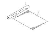
- a resin pipe (temporary core) 11 longer than the width of the hollow fiber sheet 4 is prepared. And as shown in FIG. 7, after making the length direction of this resin pipe 11 and the width direction of the hollow fiber sheet 4 correspond, and leaving the both ends of the resin pipe 11 a little, the hollow fiber sheet 4 is made moderate. It is wound around the resin pipe 11 while being pulled by tension.
- the number of windings may be one, but from a practical point of view, the effective membrane area of the yarn bundle 3 in the housing body 5a (the total area of the surface of the hollow fiber 2 in contact with the liquid) is 0.005 m 2 ⁇ 1. is preferably set to .0m 2, it is preferable that the particular 0.01m 2 ⁇ 0.5m 2.
- the filling rate (value obtained by dividing the difference between the cross-sectional area of the housing body 5a and the center hole 3a by the sum of the cross-sectional areas of the hollow fibers 2 as a percentage) is 5% to 50%. It is preferable to be 10% to 40%, and it is particularly preferable to be 20% to 30%.
- a thin resin temporary fixing sheet 12 is prepared. Then, as shown in FIG. 8, the temporary fixing sheet 12 is wound in close contact with the outer periphery of the hollow fiber sheet 4 wound around the resin pipe 11 without play. Once the temporary fixing sheet 12 is wound around the outer periphery of the hollow fiber sheet 4, the end of the temporary fixing sheet 12 is bonded to the temporary fixing sheet 12 itself so that the hollow fiber sheet 4 is not separated from the resin pipe 11. Then, it is left in a predetermined temperature environment and left for a predetermined time.
- the resin pipe 11 is slightly shifted from the hollow fiber sheet 4, and then the hollow fiber sheet 4 is cut using a pipe cutter. To do. At this time, the width of the hollow fiber sheet 4 is made slightly longer than that of the housing body 5 a that houses the yarn bundle 3.
- the above-described cutting operation is repeated to cut the original roll in which the hollow fiber sheet 4 is wound around the resin pipe 11 into a plurality of unit rolls Ru. Thereafter, the resin pipe 11 is slightly shifted with respect to the hollow fiber sheet 4 for each of the cut unit rolls Ru, so that both ends of the resin pipe 11 are slightly left from the hollow fiber sheet 4.
- the temporary fixing sheet 12 is removed from the unit roll Ru and left for a predetermined time.
- the sealing resin E1 is cured, and one end of a large number of hollow fibers 2 arranged at one end of the yarn bundle 3 around the resin pipe 11 is bonded to each other, and each hollow fiber 2 opened at one end of the yarn bundle 3
- the hole 2a is sealed (see FIG. 3). Furthermore, one end of the yarn bundle 3 is bonded to the housing body 5a.
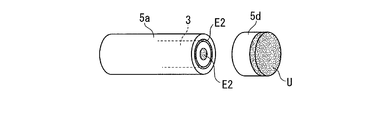
- a header 5d for supplying the sealing resin E2 to the other end of the yarn bundle 3 in the process of centrifugal sealing described later is integrally formed.
- the header 5d is finally cut out from the housing body 5a.
- an uncured sealing resin for example, urethane resin, epoxy resin, ultraviolet curable resin, etc.
- U is poured into the recess 15 a of the centrifugal sealing jig 15.
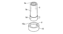
- the housing body 5 a accommodating the yarn bundle 3 is placed on the centrifugal sealing jig 15 with the other end facing down.
- the sealing resin U is supplied to the other end of the yarn bundle 3 accommodated in the housing main body 5 a set up on the centrifugal sealing jig 15. Thereafter, the housing body 5a set up on the centrifugal sealing jig 15 is left for a predetermined time.
- the housing body 5a to which the centrifugal sealing jig 15 is bonded is applied to the centrifugal sealing device.
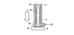
- the centrifugal sealing device supplies the sealing resin (for example, urethane resin, epoxy resin, ultraviolet curable resin, etc.) E2 to the other end of the yarn bundle 3 through the header 5d formed on the housing body 5a, A centrifugal force is applied for a predetermined time from one end of the bundle 3 to the other end (in the direction of arrow F in the figure).
- the sealing resin E2 is filled and cured to a level W in the figure, and the other ends of the multiple hollow fibers 2 arranged on the other end of the yarn bundle 3 are bonded to each other, and the center opening at the other end of the yarn bundle 3 is opened.
- the hole 3a is sealed (see FIG. 4).
- a first cap 5b is attached to one end of the housing body 5a, and a second cap 5c is attached to the other end. If necessary, an adhesive is filled between the first and second caps 5b, 5c and the housing body 5a to reinforce. Through the above steps, the degassing hollow fiber module 1 shown in FIGS. 1 to 6 is completed.
- the degassing hollow fiber module of the present embodiment after the sheet 4 including a large number of hollow fibers 2 is wound around the resin pipe 11 as a temporary core and held in a cylindrical shape, By removing the resin pipe 11 from the hollow fiber sheet 4 held in the shape of the hollow fiber 2, only the hollow fiber 2 is secured without rigidity and having no core as a support base for the hollow fiber, and causing less pressure loss when flowing ink. Module can be manufactured.
- the sealing resin E1 is attached to one end of the cylindrical hollow fiber sheet 4 before removing the resin pipe 11 from the cylindrical sheet 4.
- the ends of the hollow fibers 2 arranged at one end of the hollow fiber sheet 4 are bonded to each other and the holes 2 a of the hollow fibers 2 opened at one end of the hollow fiber sheet 4 are sealed.
- the center hole 3a of the hollow fiber sheet 4 is secured by a core as a support base in the conventional degassing hollow fiber module, but also in the degassing hollow fiber module 1 of the present embodiment having no core.
- the central hole 3a can be easily secured by the above method.
- a sealing resin is attached to the other end of the cylindrical hollow fiber sheet 4.
- E2 is supplied, the other ends of the multiple hollow fibers 2 arranged on the other end of the hollow fiber sheet 4 are bonded to each other, and the other end of the central hole 3a that opens to the other end of the hollow fiber sheet 4 is filled with the sealing resin E2 Is possible.
- the other end of the center hole 3a of the hollow fiber sheet 4 is closed by a core as a support base in the conventional deaeration hollow fiber module, but the deaeration hollow fiber module of the present embodiment having no core is provided. 1, the other end of the central hole 3a can be easily closed.
- one end of the yarn bundle 3 is statically sealed and the other end is centrifugally sealed, but the method of sealing may be either stationary or centrifugal.
- one end of the unit roll may be sealed by centrifugation and the other end may be statically sealed.
- both ends of the unit roll may be statically sealed, and both ends may be centrifugally sealed.
- Modification 1 In Modification 1, as shown in FIG. 16, a plurality of through holes 16 are formed in the wall of the resin pipe 11. Then, the inside of the resin pipe 11 is evacuated to suck the starting end of the hollow fiber sheet 4 through the through hole 16 to the resin pipe 11. Thereby, the hollow fiber sheet 4 can be easily wound around the resin pipe 11.
- Modification 2 In Modification 2, as shown in FIG. 17, a plurality of claws 17 are formed on the outer peripheral surface of the resin pipe 11 in one direction in the circumferential direction. Then, after the hollow fiber sheet 4 is hooked on the claw, the resin pipe 11 is rotated in the direction of the claw 17 and the hollow fiber sheet 4 is wound around the resin pipe 11. After the winding is completed, the resin pipe 11 is gradually extracted from the hollow fiber sheet 4 by rotating the resin pipe 11 in the reverse direction. Thereby, the hollow fiber sheet 4 can be easily wound around the resin pipe 11.
- the claw 17 may be a mechanism that can be mechanically inserted and removed from the outer peripheral surface of the resin pipe 11.
- the claw 17 When the hollow fiber sheet 4 is wound around the resin pipe 11, the claw 17 is protruded from the outer peripheral surface of the resin pipe 17 to hook the hollow fiber sheet 4. By immersing in, the claw 17 can be removed without interfering with the hollow fiber sheet 4, so that the hollow fiber sheet 4 is not damaged.
- the present invention is a method for producing a hollow fiber module for deaeration without a core, the step of winding a sheet containing a number of hollow fibers around a temporary core, and the above-mentioned wound around the temporary core
- the present invention relates to a method for manufacturing a degassing hollow fiber module comprising a step of holding a sheet in a cylindrical shape and a step of removing the temporary core from the sheet held in a cylindrical shape.
- the rigidity is ensured and the core as a support base of the hollow fiber is not satisfied, so that the requirement for miniaturization is satisfied and the processing object is caused to flow.
- a degassing hollow fiber module with low pressure loss can be manufactured easily and with high accuracy.
Landscapes
- Chemical & Material Sciences (AREA)
- Chemical Kinetics & Catalysis (AREA)
- Engineering & Computer Science (AREA)
- Manufacturing & Machinery (AREA)
- Separation Using Semi-Permeable Membranes (AREA)
- Degasification And Air Bubble Elimination (AREA)
Abstract
Description
2…中空糸
2a…孔
2b…経糸(たていと)
3…糸束
3a…中央穴
4…中空糸シート
5…ハウジング
5a…ハウジング本体
5b,5c…キャップ
5d…ヘッダ
6…インク排出口
7…円鍔部
8…爪
9…インク導入口
10…吸引口
11…樹脂パイプ
12…仮止シート
13…静置治具
14…軸
15…遠心封止治具
E1,E2,U…封止樹脂
本発明の脱気用中空糸モジュールの製造方法においては、多数の中空糸を含むシートを仮芯に巻き付けて筒状に保持し、筒状に保持された前記シートの一端に樹脂を供給し、前記シートの一端に並ぶ前記多数の中空糸の一端を互いに接着するとともに前記シートの一端に開口する各中空糸の孔を封止する工程を備え、前記樹脂が硬化した後、前記シートから前記仮芯を除去してもよい。なお、多数の中空糸を含むシートは、中空糸を網目状に編んだシートであってもよいが、インクなどの液体を流した場合に、全中空糸に均等に液体を接触させることができ、効率的に脱泡処理ができることから、多数の中空糸の全てが略平行に配列されたシートとすることが好ましい。
まず、図1および図2に、筒状の芯をもたない脱気用中空糸モジュールの構造を示す。この芯無しの脱気用中空糸モジュール1は、多数の中空糸の束3と、糸束3を収容するハウジング5とからなる。糸束3は、図5に示すように、同列に並ぶ多数の中空糸2を経糸2bで編み上げたシート4を、多数の中空糸2の長さ方向と平行な軸を中心として円筒状に巻き込んだものである。糸束3の長さ方向に直交する断面の中央には、中空糸2の長さ方向に平行な中央穴3aが設けられている。
なお、ハウジング本体5aと第一、第二のキャップ5b,5cとの固定強度を高めるために、爪8と円鍔部7との掛止構造に代えて、雄ネジと雌ネジとの螺合構造を採用しても構わない。
(中空糸シートの裁断)
ポリ-4メチルペンテン-1を素材とした不均質構造の側壁(膜)を有する内径100μm、外径180μmの中空糸2を用意し、同列に並ぶ多数の中空糸2を経糸2bで編み上げた中空糸シート4(図5及び図7を参照)を、適当な大きさに裁断する。中空糸シート4の幅(中空糸2方向の寸法)は、糸束3を収容するハウジング本体5aの長さの整数倍よりも若干長く、かつ中空糸シート4の長さ(経糸2b方向の寸法)は、裁断した中空糸シート4を適度な張力で引っ張りながら後述する仮芯に巻き付けたときに、その原ロールの外径がハウジング本体5aの内径よりも若干小さくなる程度とする。なお、本実施例では、原ロールを二つに切断して単位ロールを得るため、中空糸シート4の幅がハウジング本体5aの長さの2倍よりも若干長くなっているが、原ロールの製作を省いて当初から単位ロールを製作するのであれば、中空糸シート4の幅はハウジング本体5aよりも若干長ければよい。その場合は、後述する原ロールの切断工程も省略される。
中空糸シート4の幅よりも長い樹脂パイプ(仮芯)11を用意する。そして、図7に示すように、この樹脂パイプ11の長さ方向と中空糸シート4の幅方向とを一致させるとともに樹脂パイプ11の両端を少し余らせたうえで、中空糸シート4を適度な張力で引っ張りながら樹脂パイプ11に巻き付ける。なお、巻き付け回数は1回でも良いが、実用的な点からは、ハウジング本体5a内における糸束3の有効膜面積(液体と接する中空糸2の表面の総面積)を0.005m2~1.0m2とすることが好ましく、特に0.01m2~0.5m2とすることが好ましい。また、充填率(ハウジング本体5aの断面積と中央穴3aの面積の差を、各中空糸2の断面積の総和で割った値を百分率で表した値)としては、5%~50%となるようにすることが好ましく、10%~40%となるようにすることがより好ましく、特に20%~30%となるようにすることが好ましい。
薄い樹脂製の仮止シート12を用意する。そして、図8に示すように、この仮止シート12を、樹脂パイプ11に巻き付けられた中空糸シート4の外周に遊びのないように密着させて巻き付ける。仮止シート12を中空糸シート4の外周にひと巻きしたら、樹脂パイプ11から中空糸シート4が離れないように、仮止シート12の終端を仮止シート12自身に接着する。その後、所定の温度環境下に置いて所定の時間放置する。
中空糸シート4を樹脂パイプ11に巻き付けた原ロールについて、図9に示すように、中空糸シート4に対して樹脂パイプ11を少しずらしたうえで、パイプカッターを用いて中空糸シート4を切断する。このとき、中空糸シート4の幅を、糸束3を収容するハウジング本体5aよりも若干長めにする。上記の切断作業を繰り返して、中空糸シート4を樹脂パイプ11に巻き付けた原ロールを複数の単位ロールRuに切り分ける。その後、切り分けられた個々の単位ロールRuについて、中空糸シート4に対して樹脂パイプ11を少しずらし、樹脂パイプ11の両端を中空糸シート4から少し余らせる。
静置治具13に離型剤を塗布したうえで、静置治具13の凹み13aに未硬化の封止樹脂(例えば、ウレタン樹脂、エポキシ樹脂、紫外線硬化型樹脂など)E1を注ぐ。次に、図10に示すように、静置治具13に直立させた軸14を樹脂パイプ11の穴にさし込み、単位ロールRuを静置治具13に立てる。封止樹脂E1は、静置治具13に立てられた単位ロールRuの一端に供給される。このとき、封止樹脂E1が仮止シート12に付着しないように、仮止シート12を中空糸シート4に対して上方にずらす。
封止樹脂E1が硬化したら、図12に示すように、ハウジング本体5aの内側に固定された単位ロールRuを静置治具13から取り外し、単位ロールRuから樹脂パイプ11を抜き取る。樹脂パイプ11が抜き取られると、ハウジング本体5aの内部には糸束3だけが残り、中央穴3aが開口する。
遠心封止治具15に離型剤を塗布したうえで、遠心封止治具15の凹み15aに未硬化の封止樹脂(例えば、ウレタン樹脂、エポキシ樹脂、紫外線硬化型樹脂など)Uを注ぐ。次に、図13に示すように、糸束3を収容したハウジング本体5aを、その他端を下にして遠心封止治具15に立てる。封止樹脂Uは、遠心封止治具15に立てられたハウジング本体5aに収容された糸束3の他端に供給される。その後、遠心封止治具15に立てられたハウジング本体5aを所定の時間放置する。
封止樹脂E2が硬化したら、図15に示すように、糸束3を収容したハウジング本体5aを切断し、ヘッダ5dを遠心封止治具15とともにハウジング本体5aから切除する。ヘッダ5dが切除されると、糸束3の他端には、各中空糸2の他端の孔2aが開口する(中央穴は封止樹脂E2によって封止されたままである)。
ハウジング本体5aの一端に第一のキャップ5bを被着し、他端に第二のキャップ5cを被着する。必要があれば、第一、第二のキャップ5b,5cとハウジング本体5aとの間に接着剤を充填し、補強する。上記の工程を経て、図1から図6に示す脱気用中空糸モジュール1が完成する。
(変形例1)
変形例1では、図16に示すように、樹脂パイプ11の壁に複数の貫通孔16が形成されている。そして、樹脂パイプ11の内側が真空引きされることにより、貫通孔16を通じて中空糸シート4の始端を樹脂パイプ11に吸い付ける。これにより、樹脂パイプ11に中空糸シート4を簡単に巻き付けることができる。
変形例2では、図17に示すように、樹脂パイプ11の外周面に周方向の一方に向かう複数の爪17が形成されている。そして、中空糸シート4を爪に引っ掛けたうえで樹脂パイプ11を爪17の向きに回転させるようにして中空糸シート4を樹脂パイプ11に巻き付ける。巻き終えた後は、樹脂パイプ11を逆方向に回転させるようにして徐々に中空糸シート4から樹脂パイプ11を抜き取る。これにより、樹脂パイプ11に中空糸シート4を簡単に巻き付けることができる。なお、爪17は、樹脂パイプ11の外周面から機械的に出し入れ可能な機構とされていてもよい。樹脂パイプ11に中空糸シート4を巻き付けるときには、爪17を樹脂パイプ17の外周面から突き出させて中空糸シート4を引っ掛け、中空糸シート4から樹脂パイプ11を抜き取るときには、爪17を樹脂パイプ17内に没入させることで、爪17が中空糸シート4に干渉することなく取り除けるので、中空糸シート4を傷付けることがない。
Claims (3)
- 仮芯のまわりに、多数の中空糸を含むシートを巻く工程と、
前記仮芯のまわりに巻かれた前記シートを筒状に保持する工程と、
筒状に保持された前記シートから、前記仮芯を除去する工程と
を備えることを特徴とする脱気用中空糸モジュールの製造方法。 - 筒状に保持された前記シートの一端に樹脂を供給し、前記シートの一端に並ぶ前記多数の中空糸の一端を互いに接着するとともに前記シートの一端に開口する各中空糸の孔を封止する工程を備え、
前記樹脂が硬化した後、前記シートから前記仮芯を除去する請求項1に記載の脱気用中空糸モジュールの製造方法。 - 前記仮芯を除去されたシートの他端に樹脂を供給し、前記シートの他端に並ぶ前記多数の中空糸の他端を互いに接着するとともに前記シートの他端に開口する穴に前記樹脂を充填する工程を備える請求項1または2に記載の脱気用中空糸モジュールの製造方法。
Priority Applications (10)
| Application Number | Priority Date | Filing Date | Title |
|---|---|---|---|
| US12/736,975 US8449706B2 (en) | 2008-05-30 | 2008-05-30 | Process for manufacturing deaerating hollow fiber module |
| PCT/JP2008/060020 WO2009144813A1 (ja) | 2008-05-30 | 2008-05-30 | 脱気用中空糸モジュールの製造方法 |
| CN200880129512.0A CN102046271B (zh) | 2008-05-30 | 2008-05-30 | 脱气用中空丝组件的制造方法 |
| ES08777031T ES2728399T3 (es) | 2008-05-30 | 2008-05-30 | Procedimiento de fabricación de un módulo de fibras huecas para desaireación |
| KR1020107028031A KR101465295B1 (ko) | 2008-05-30 | 2008-05-30 | 탈기용 중공사 모듈의 제조 방법 |
| CA2726155A CA2726155C (en) | 2008-05-30 | 2008-05-30 | Deaerating hollow fiber module formed from sheet and temporary core |
| HK11107640.6A HK1153422B (en) | 2008-05-30 | Process for manufacturing deaerating hollow fiber module | |
| JP2010514306A JP4730483B2 (ja) | 2008-05-30 | 2008-05-30 | 脱気用中空糸モジュールの製造方法 |
| EP08777031.9A EP2292318B1 (en) | 2008-05-30 | 2008-05-30 | Process for manufacturing a hollow fiber module for deaeration |
| IL209644A IL209644A (en) | 2008-05-30 | 2010-11-30 | Process for manufacturing hollow fiber module without air |
Applications Claiming Priority (1)
| Application Number | Priority Date | Filing Date | Title |
|---|---|---|---|
| PCT/JP2008/060020 WO2009144813A1 (ja) | 2008-05-30 | 2008-05-30 | 脱気用中空糸モジュールの製造方法 |
Publications (1)
| Publication Number | Publication Date |
|---|---|
| WO2009144813A1 true WO2009144813A1 (ja) | 2009-12-03 |
Family
ID=41376712
Family Applications (1)
| Application Number | Title | Priority Date | Filing Date |
|---|---|---|---|
| PCT/JP2008/060020 Ceased WO2009144813A1 (ja) | 2008-05-30 | 2008-05-30 | 脱気用中空糸モジュールの製造方法 |
Country Status (9)
| Country | Link |
|---|---|
| US (1) | US8449706B2 (ja) |
| EP (1) | EP2292318B1 (ja) |
| JP (1) | JP4730483B2 (ja) |
| KR (1) | KR101465295B1 (ja) |
| CN (1) | CN102046271B (ja) |
| CA (1) | CA2726155C (ja) |
| ES (1) | ES2728399T3 (ja) |
| IL (1) | IL209644A (ja) |
| WO (1) | WO2009144813A1 (ja) |
Cited By (2)
| Publication number | Priority date | Publication date | Assignee | Title |
|---|---|---|---|---|
| JP2019013921A (ja) * | 2013-07-24 | 2019-01-31 | 三菱ケミカル株式会社 | 外部灌流型の中空糸膜モジュール及び前記モジュールを有するインクジェットプリンタ |
| DE102018129165A1 (de) * | 2018-11-20 | 2020-05-20 | UMS Gmbh & Co KG | Gasdruckmessvorrichtung mit Hohlfasermembranbündel |
Families Citing this family (7)
| Publication number | Priority date | Publication date | Assignee | Title |
|---|---|---|---|---|
| CN102580541B (zh) * | 2012-02-15 | 2013-12-18 | 东莞信诺能源科技有限公司 | 可上下叠层连续锁合的导水盘及导水盘组 |
| JP3195924U (ja) | 2014-11-28 | 2015-02-12 | Dic株式会社 | 中空糸脱気モジュール及びインクジェットプリンタ |
| CA2969317C (en) | 2014-12-24 | 2023-06-13 | Dic Corporation | Hollow-fiber degassing module and inkjet printer |
| ES2961836T3 (es) * | 2014-12-24 | 2024-03-14 | Dainippon Ink & Chemicals | Procedimiento de desgasificación en un módulo de desgasificación de fibra hueca |
| KR101874816B1 (ko) * | 2016-06-29 | 2018-07-05 | 앵스트롬스 주식회사 | 기액접촉 및 탈기를 위한 중공사 맴브레인 필터 |
| JP6854822B2 (ja) * | 2016-08-17 | 2021-04-07 | 三菱ケミカル・クリンスイ株式会社 | 中空糸膜モジュール、脱気給気装置、インクジェットプリンタおよび炭酸泉製造装置 |
| WO2023039585A1 (en) | 2021-09-10 | 2023-03-16 | Pentair, Inc. | Fiber membrane bundle without a core |
Citations (12)
| Publication number | Priority date | Publication date | Assignee | Title |
|---|---|---|---|---|
| JPS6115712A (ja) * | 1984-06-29 | 1986-01-23 | Kanebo Ltd | カ−トリツジフイルタ |
| JPS63236502A (ja) * | 1987-03-10 | 1988-10-03 | アクゾ・エヌ・ヴエー | 多層中空繊維巻体、その製法、熱伝達法、物質交換法、物質転送法、物質分離法、透析法及び酸素付加法 |
| JPH02107317A (ja) | 1988-10-14 | 1990-04-19 | Dainippon Ink & Chem Inc | 多孔質中空糸膜型気液接触装置 |
| JPH0517712A (ja) | 1991-07-08 | 1993-01-26 | Seiko Epson Corp | インクジエツト記録用インクの脱気方法 |
| JPH05245347A (ja) | 1991-12-31 | 1993-09-24 | Hoechst Celanese Corp | 流れ差向けバッフルを持つ螺旋状に巻付けた中空糸膜織物カートリッジ及びモジュール |
| JPH05245348A (ja) | 1991-12-31 | 1993-09-24 | Hoechst Celanese Corp | 一体式乱流プロモーターを有する渦巻き形中空繊維膜織物カートリッジ及びモジュール |
| JPH05299978A (ja) | 1992-04-20 | 1993-11-12 | Toshiba Corp | コンパレータ |
| JPH0788304A (ja) * | 1993-09-21 | 1995-04-04 | Mitsubishi Rayon Co Ltd | 溶存ガス除去およびガス給気モジュール |
| WO1998028065A1 (en) * | 1996-12-24 | 1998-07-02 | Kitz Corporation | Hollow-fiber membrane module and process for the production thereof |
| JPH10298470A (ja) | 1997-04-30 | 1998-11-10 | Mitsubishi Rayon Co Ltd | インクの脱気方法及びインク脱気装置 |
| JP2002361050A (ja) | 2001-05-08 | 2002-12-17 | Celgard Inc | 中空糸膜接触器とその製造方法 |
| JP2005305432A (ja) | 2001-03-22 | 2005-11-04 | Celgard Inc | インキ脱泡システム |
Family Cites Families (8)
| Publication number | Priority date | Publication date | Assignee | Title |
|---|---|---|---|---|
| JPS5299978A (en) | 1976-02-17 | 1977-08-22 | Mitsubishi Rayon Co Ltd | Fluid separating apparatus used hollow yarn |
| US4210536A (en) * | 1978-09-19 | 1980-07-01 | Albany International Corp. | Hollow filament separatory module |
| JP3338087B2 (ja) * | 1992-07-31 | 2002-10-28 | エヌオーケー株式会社 | 遠心ポッティング装置 |
| US5284584A (en) | 1992-12-31 | 1994-02-08 | Hoechst Celanese Corporation | Hollow fiber membrane fabric - containing cartridges and modules having solvent-resistant thermoplastic tube sheets, and methods for making the same |
| EP1468437A2 (en) * | 2001-09-24 | 2004-10-20 | FEI Company | Electrostatic manipulating apparatus |
| NL1019374C2 (nl) | 2001-11-15 | 2003-05-16 | Norit Holding N V | Werkwijze voor het vervaardigen van een filtermodule, een dergelijke al dan niet in een filtersysteem opgenomen filtermodule. |
| WO2007040036A1 (ja) * | 2005-09-30 | 2007-04-12 | Kureha Corporation | 中空糸スダレ状物、中空糸束の製造方法、筒型中空糸膜モジュールおよび浸漬型中空糸膜モジュール |
| US20090156875A1 (en) | 2006-04-04 | 2009-06-18 | Takafumi Tomioka | Methane separation method, methane separation apparatus, and methane utilization system |
-
2008
- 2008-05-30 WO PCT/JP2008/060020 patent/WO2009144813A1/ja not_active Ceased
- 2008-05-30 EP EP08777031.9A patent/EP2292318B1/en active Active
- 2008-05-30 US US12/736,975 patent/US8449706B2/en active Active
- 2008-05-30 CA CA2726155A patent/CA2726155C/en active Active
- 2008-05-30 ES ES08777031T patent/ES2728399T3/es active Active
- 2008-05-30 CN CN200880129512.0A patent/CN102046271B/zh active Active
- 2008-05-30 JP JP2010514306A patent/JP4730483B2/ja active Active
- 2008-05-30 KR KR1020107028031A patent/KR101465295B1/ko active Active
-
2010
- 2010-11-30 IL IL209644A patent/IL209644A/en active IP Right Grant
Patent Citations (12)
| Publication number | Priority date | Publication date | Assignee | Title |
|---|---|---|---|---|
| JPS6115712A (ja) * | 1984-06-29 | 1986-01-23 | Kanebo Ltd | カ−トリツジフイルタ |
| JPS63236502A (ja) * | 1987-03-10 | 1988-10-03 | アクゾ・エヌ・ヴエー | 多層中空繊維巻体、その製法、熱伝達法、物質交換法、物質転送法、物質分離法、透析法及び酸素付加法 |
| JPH02107317A (ja) | 1988-10-14 | 1990-04-19 | Dainippon Ink & Chem Inc | 多孔質中空糸膜型気液接触装置 |
| JPH0517712A (ja) | 1991-07-08 | 1993-01-26 | Seiko Epson Corp | インクジエツト記録用インクの脱気方法 |
| JPH05245347A (ja) | 1991-12-31 | 1993-09-24 | Hoechst Celanese Corp | 流れ差向けバッフルを持つ螺旋状に巻付けた中空糸膜織物カートリッジ及びモジュール |
| JPH05245348A (ja) | 1991-12-31 | 1993-09-24 | Hoechst Celanese Corp | 一体式乱流プロモーターを有する渦巻き形中空繊維膜織物カートリッジ及びモジュール |
| JPH05299978A (ja) | 1992-04-20 | 1993-11-12 | Toshiba Corp | コンパレータ |
| JPH0788304A (ja) * | 1993-09-21 | 1995-04-04 | Mitsubishi Rayon Co Ltd | 溶存ガス除去およびガス給気モジュール |
| WO1998028065A1 (en) * | 1996-12-24 | 1998-07-02 | Kitz Corporation | Hollow-fiber membrane module and process for the production thereof |
| JPH10298470A (ja) | 1997-04-30 | 1998-11-10 | Mitsubishi Rayon Co Ltd | インクの脱気方法及びインク脱気装置 |
| JP2005305432A (ja) | 2001-03-22 | 2005-11-04 | Celgard Inc | インキ脱泡システム |
| JP2002361050A (ja) | 2001-05-08 | 2002-12-17 | Celgard Inc | 中空糸膜接触器とその製造方法 |
Non-Patent Citations (1)
| Title |
|---|
| See also references of EP2292318A4 |
Cited By (2)
| Publication number | Priority date | Publication date | Assignee | Title |
|---|---|---|---|---|
| JP2019013921A (ja) * | 2013-07-24 | 2019-01-31 | 三菱ケミカル株式会社 | 外部灌流型の中空糸膜モジュール及び前記モジュールを有するインクジェットプリンタ |
| DE102018129165A1 (de) * | 2018-11-20 | 2020-05-20 | UMS Gmbh & Co KG | Gasdruckmessvorrichtung mit Hohlfasermembranbündel |
Also Published As
| Publication number | Publication date |
|---|---|
| US8449706B2 (en) | 2013-05-28 |
| ES2728399T3 (es) | 2019-10-24 |
| US20110146891A1 (en) | 2011-06-23 |
| EP2292318A1 (en) | 2011-03-09 |
| JP4730483B2 (ja) | 2011-07-20 |
| IL209644A0 (en) | 2011-02-28 |
| KR101465295B1 (ko) | 2014-11-26 |
| EP2292318A4 (en) | 2012-07-04 |
| CA2726155A1 (en) | 2009-12-03 |
| CA2726155C (en) | 2018-09-04 |
| IL209644A (en) | 2015-10-29 |
| HK1153422A1 (zh) | 2012-03-30 |
| CN102046271B (zh) | 2016-01-06 |
| EP2292318B1 (en) | 2019-03-06 |
| KR20110011686A (ko) | 2011-02-08 |
| JPWO2009144813A1 (ja) | 2011-09-29 |
| CN102046271A (zh) | 2011-05-04 |
Similar Documents
| Publication | Publication Date | Title |
|---|---|---|
| JP4730483B2 (ja) | 脱気用中空糸モジュールの製造方法 | |
| JP6788014B2 (ja) | 外部潅流型中空糸膜モジュール | |
| JP6168056B2 (ja) | 中空糸膜モジュール | |
| WO1998048926A1 (en) | Ink deaerating hollow yarn membrane, ink deaerating method, ink deaerating apparatus, ink cartridge manufacturing method, and ink | |
| CN103826729B (zh) | 改进的接触器、筒、组件、系统和相关方法 | |
| JP7683745B2 (ja) | 脱気モジュール及び液体の脱気方法 | |
| CN100361729C (zh) | 用于形成气体传递膜的褶式结构 | |
| JP6396795B2 (ja) | 医療器具の製造方法 | |
| CN107106936B (zh) | 中空纤维脱气组件以及喷墨打印机 | |
| JPH11244607A (ja) | 薬液の脱気方法及び脱気装置 | |
| JP5935808B2 (ja) | 中空糸膜モジュールの親水化方法 | |
| JP5080781B2 (ja) | 脱気用中空糸膜モジュール及び脱気装置 | |
| TWI435758B (zh) | 排氣用中空絲模組之製造方法 | |
| JP2006082036A (ja) | 中空糸膜モジュール | |
| HK1153422B (en) | Process for manufacturing deaerating hollow fiber module | |
| JP4375780B2 (ja) | 中空糸膜モジュールの製造方法 | |
| JP7510344B2 (ja) | 中空糸膜モジュール、中空糸膜モジュールの製造方法、及びろ過方法 | |
| WO2025239141A1 (ja) | 脱気モジュール及び液体の脱気方法 | |
| WO2026094775A1 (ja) | 中空糸膜エレメントの製造方法、中空糸膜エレメント、及び中空糸膜モジュール | |
| JP2006082035A (ja) | 中空糸膜モジュールの製造方法 |
Legal Events
| Date | Code | Title | Description |
|---|---|---|---|
| WWE | Wipo information: entry into national phase |
Ref document number: 200880129512.0 Country of ref document: CN |
|
| 121 | Ep: the epo has been informed by wipo that ep was designated in this application |
Ref document number: 08777031 Country of ref document: EP Kind code of ref document: A1 |
|
| WWE | Wipo information: entry into national phase |
Ref document number: 2010514306 Country of ref document: JP |
|
| WWE | Wipo information: entry into national phase |
Ref document number: 2726155 Country of ref document: CA |
|
| WWE | Wipo information: entry into national phase |
Ref document number: 12736975 Country of ref document: US |
|
| NENP | Non-entry into the national phase |
Ref country code: DE |
|
| WWE | Wipo information: entry into national phase |
Ref document number: 2008777031 Country of ref document: EP |
|
| ENP | Entry into the national phase |
Ref document number: 20107028031 Country of ref document: KR Kind code of ref document: A |