WO2010035542A1 - Structure de montage pour partie intérieure de véhicule - Google Patents
Structure de montage pour partie intérieure de véhicule Download PDFInfo
- Publication number
- WO2010035542A1 WO2010035542A1 PCT/JP2009/058674 JP2009058674W WO2010035542A1 WO 2010035542 A1 WO2010035542 A1 WO 2010035542A1 JP 2009058674 W JP2009058674 W JP 2009058674W WO 2010035542 A1 WO2010035542 A1 WO 2010035542A1
- Authority
- WO
- WIPO (PCT)
- Prior art keywords
- engagement
- panel
- lower panel
- console
- engaged
- Prior art date
- Legal status (The legal status is an assumption and is not a legal conclusion. Google has not performed a legal analysis and makes no representation as to the accuracy of the status listed.)
- Ceased
Links
Images



Classifications
-
- B—PERFORMING OPERATIONS; TRANSPORTING
- B60—VEHICLES IN GENERAL
- B60R—VEHICLES, VEHICLE FITTINGS, OR VEHICLE PARTS, NOT OTHERWISE PROVIDED FOR
- B60R7/00—Stowing or holding appliances inside vehicle primarily intended for personal property smaller than suit-cases, e.g. travelling articles, or maps
- B60R7/04—Stowing or holding appliances inside vehicle primarily intended for personal property smaller than suit-cases, e.g. travelling articles, or maps in driver or passenger space, e.g. using racks
-
- B—PERFORMING OPERATIONS; TRANSPORTING
- B60—VEHICLES IN GENERAL
- B60K—ARRANGEMENT OR MOUNTING OF PROPULSION UNITS OR OF TRANSMISSIONS IN VEHICLES; ARRANGEMENT OR MOUNTING OF PLURAL DIVERSE PRIME-MOVERS IN VEHICLES; AUXILIARY DRIVES FOR VEHICLES; INSTRUMENTATION OR DASHBOARDS FOR VEHICLES; ARRANGEMENTS IN CONNECTION WITH COOLING, AIR INTAKE, GAS EXHAUST OR FUEL SUPPLY OF PROPULSION UNITS IN VEHICLES
- B60K35/00—Instruments specially adapted for vehicles; Arrangement of instruments in or on vehicles
- B60K35/60—Instruments characterised by their location or relative disposition in or on vehicles
-
- B—PERFORMING OPERATIONS; TRANSPORTING
- B60—VEHICLES IN GENERAL
- B60K—ARRANGEMENT OR MOUNTING OF PROPULSION UNITS OR OF TRANSMISSIONS IN VEHICLES; ARRANGEMENT OR MOUNTING OF PLURAL DIVERSE PRIME-MOVERS IN VEHICLES; AUXILIARY DRIVES FOR VEHICLES; INSTRUMENTATION OR DASHBOARDS FOR VEHICLES; ARRANGEMENTS IN CONNECTION WITH COOLING, AIR INTAKE, GAS EXHAUST OR FUEL SUPPLY OF PROPULSION UNITS IN VEHICLES
- B60K37/00—Dashboards
- B60K37/10—Arrangements for attaching the dashboard to the vehicle
-
- B—PERFORMING OPERATIONS; TRANSPORTING
- B60—VEHICLES IN GENERAL
- B60K—ARRANGEMENT OR MOUNTING OF PROPULSION UNITS OR OF TRANSMISSIONS IN VEHICLES; ARRANGEMENT OR MOUNTING OF PLURAL DIVERSE PRIME-MOVERS IN VEHICLES; AUXILIARY DRIVES FOR VEHICLES; INSTRUMENTATION OR DASHBOARDS FOR VEHICLES; ARRANGEMENTS IN CONNECTION WITH COOLING, AIR INTAKE, GAS EXHAUST OR FUEL SUPPLY OF PROPULSION UNITS IN VEHICLES
- B60K2360/00—Indexing scheme associated with groups B60K35/00 or B60K37/00 relating to details of instruments or dashboards
- B60K2360/77—Instrument locations other than the dashboard
- B60K2360/774—Instrument locations other than the dashboard on or in the centre console
-
- B—PERFORMING OPERATIONS; TRANSPORTING
- B60—VEHICLES IN GENERAL
- B60R—VEHICLES, VEHICLE FITTINGS, OR VEHICLE PARTS, NOT OTHERWISE PROVIDED FOR
- B60R13/00—Elements for body-finishing, identifying, or decorating; Arrangements or adaptations for advertising purposes
- B60R13/02—Internal Trim mouldings ; Internal Ledges; Wall liners for passenger compartments; Roof liners
- B60R13/0256—Dashboard liners
-
- B—PERFORMING OPERATIONS; TRANSPORTING
- B60—VEHICLES IN GENERAL
- B60R—VEHICLES, VEHICLE FITTINGS, OR VEHICLE PARTS, NOT OTHERWISE PROVIDED FOR
- B60R13/00—Elements for body-finishing, identifying, or decorating; Arrangements or adaptations for advertising purposes
- B60R13/02—Internal Trim mouldings ; Internal Ledges; Wall liners for passenger compartments; Roof liners
- B60R13/0262—Mid-console liners
-
- B—PERFORMING OPERATIONS; TRANSPORTING
- B60—VEHICLES IN GENERAL
- B60R—VEHICLES, VEHICLE FITTINGS, OR VEHICLE PARTS, NOT OTHERWISE PROVIDED FOR
- B60R13/00—Elements for body-finishing, identifying, or decorating; Arrangements or adaptations for advertising purposes
- B60R13/02—Internal Trim mouldings ; Internal Ledges; Wall liners for passenger compartments; Roof liners
- B60R2013/0293—Connection or positioning of adjacent panels
Definitions
- the present invention is a console member that is disposed on the floor surface of a vehicle and has a front end engaged with an instrument panel, a front end engaged with an instrument panel, and a rear end engaged with a console member.
- the present invention relates to a structure for assembling a vehicle interior part having a shift panel.
- Patent Document 1 discloses a console box mounting structure disposed so as to cover a shift device.
- the present invention has been made in view of such conventional problems, and can improve the workability of assembling the console member, which is a large interior component, and the shift panel disposed above the console member. It is an object of the present invention to provide an assembly structure for a vehicle interior part that can keep a gap or the like in a state within a certain range and ensure quality such as appearance design.
- the present invention provides a console member disposed on the floor surface of a vehicle and having a front end engaged with an instrument panel, a space provided above the console member, and a front end associated with the instrument panel. And a vehicle interior part assembly structure having a shift panel having a rear end engaged with the console member.
- the shift panel is a combination of an upper panel constituting the upper side and a lower panel constituting the lower side, At the rear end of the lower panel, an insertion portion is provided to be inserted into a recess portion provided at the rear end of the console member, The left and right outer surfaces of the insertion portion of the lower panel and the left and right inner surfaces of the recess portion of the console member facing each other insert an engagement protrusion provided on the other into an engagement recess provided on one It is configured to be engageable by The engagement recess is provided so as to restrict movement in the front-rear direction of the engagement protrusion and allow vertical position variation in a state where the engagement protrusion is engaged.
- a console engagement portion that engages with a console engagement portion provided on the instrument panel is provided at a tip of the console member, and the console engagement portion and the console engagement portion are connected to the instrument engagement portion.
- the console panel is engaged so as to allow position variation in the front-rear direction of the console member
- a lower panel engaging portion that engages with a lower panel engaging portion provided in the instrument panel is provided at a tip of the lower panel, and the lower panel engaging portion and the lower panel engaging portion are connected to the instrument.
- the lower panel is engaged with the panel so as to restrict the vertical movement of the lower panel and the forward / backward movement.
- the upper end surface of the console member and the lower end surface of the lower panel are arranged in contact with each other without being engaged with each other, and are arranged in a vehicle interior part assembly structure.
- the vehicle interior part assembly structure of the present invention can be assembled in the following procedure, for example, when the console member and the shift panel (particularly the lower panel) disposed above the console member are assembled. is there.
- problems such as a decrease in assembly workability and a decrease in appearance design, which have been problems in the past, can be solved, and an improvement in assembly workability and securing of appearance design can be realized.
- the lower panel engaging portion provided at the tip of the lower panel is engaged with the lower panel engaging portion provided in the instrument panel. Accordingly, with the position of the instrument panel as a reference, the tip of the lower panel is engaged with the instrument panel in a state where movement in the vertical direction and the front-rear direction is restricted.
- the insertion portion provided at the rear end of the lower panel is inserted into the recess portion provided at the rear end of the console member. And both are engaged by inserting the engagement protrusion part provided in the other into the engagement recessed part provided in one. Accordingly, with the position of the lower panel as a reference, the rear end of the console member is engaged with the rear end of the lower panel in a state where movement in the front-rear direction is restricted. When vertical position variations occur between the lower panel and the console member, the vertical position variations are absorbed by the engagement recesses and the engagement projections.
- the console engaging portion provided at the tip of the console member is engaged with the console engaging portion provided in the instrument panel.
- tip of the said console member is engaged with the said instrument panel.
- the top surface of the front end of the console member and the bottom surface of the front end of the lower panel are arranged with contact or a gap without engaging. That is, the front end of the console member and the front end of the lower panel are separately assembled to the instrument panel without engaging each other.
- the positions of both are adjusted.
- the rear end of the console member can be engaged with the rear end of the lower panel with reference to the position of the lower panel engaged with the instrument panel without performing operations such as positioning. Therefore, the console member and the shift panel can be easily assembled, and the workability when assembling both can be improved.
- the gaps and the like in the assembled state of both can be kept within a certain range, and there can be few variations, and quality such as appearance design can be ensured.
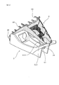
- Explanatory drawing which shows the assembly
- Explanatory drawing which shows the structure of the lower panel in an Example.
- Explanatory drawing which shows the structure of the console member in an Example.
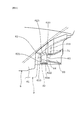
- Explanatory drawing which shows the assembly
- Explanatory drawing which shows the engagement state of the engagement protrusion part and the engagement recessed part in an Example.
- the console member is disposed on the floor surface of the vehicle, whereby the vertical position is determined. Therefore, the vertical position variation between the lower panel and the console member is the vertical position variation of the lower panel based on the position of the console member.
- a pair of said engagement protrusion part is provided in the left-right inner surface of the said hollow part of the said console member, and a pair of said engagement recessed part is provided in the outer side surface of the said insertion part of the said lower panel. It can be set as the structure provided. In this case, it is relatively easy to mold each component, and the left and right outer surfaces of the insertion portion can be easily engaged with the left and right inner surfaces of the recess portion facing these.
- the engaging recess is configured such that the inner side surface is surrounded by a front end inner side surface and a rear end inner side surface formed in the up-down direction, and an upper end inner side surface and a lower end inner side surface formed in the front-rear direction.
- the engaging protrusion is formed by the front end inner surface and the rear end inner surface.
- the engagement recess can sufficiently restrict the movement of the engagement protrusion in the front-rear direction and the position variation in the vertical direction is sufficient in a state where the engagement protrusion is engaged. Can be tolerated.
- guide groove portions for guiding the engagement protrusions into the engagement recesses communicate with the rear end inner surface side of the engagement recesses. It is preferable that the guide groove is provided so that the groove width gradually increases from the rear inner surface of the engagement recess toward the rear. In this case, by simply moving the rear end of the console member relative to the rear end of the lower panel, the engaging protrusion can be smoothly guided and inserted into the engaging recess through the guide groove. can do.
- the engagement protrusion portion engaged with the engagement recess portion is prevented from moving from the insertion port portion to the guide groove portion side. It is preferable that a movement preventing protrusion is provided. In this case, the movement preventing protrusion can prevent the engagement protrusion inserted into the engagement recess from easily coming out of the engagement recess.
- the console member has a falling corner portion formed by the top surface of the tip and a falling surface provided by falling from the rear end of the top surface of the tip, and the lower panel has the tip A rising angle portion formed between a lower surface and a rising surface provided so as to rise upward from the rear end of the lower surface of the front end, and the falling angle portion has the rising edge in a positional relationship in the front-rear direction. It is preferable that it is located in front of the corner. In this case, since the top surface of the front end of the console member enters the lower portion of the lower panel and is not exposed, the appearance of the design between the front end of the console member and the front end of the lower panel can be improved.
- an assembly structure 1 for a vehicle interior part according to this example is provided on a floor surface 10 of a vehicle, and a console member 3 having a tip engaged with a lower portion of an instrument panel 2, and a console member And a shift panel 4 having a front end engaged with the instrument panel 2 and a rear end engaged with the console member 3.
- a rear console member 11 is disposed on the rear side of the console member 3, and an armrest member 12 is disposed on the rear console member 11.
- the shift panel 4 is formed by combining an upper panel 5 constituting the upper side and a lower panel 6 constituting the lower side.
- a shift device (not shown) is accommodated inside the shift panel 4.
- the shift lever 41 connected to the shift device is provided so as to protrude upward from the inside of the shift panel 4 through the upper panel 5.
- an insertion portion 61 is provided at the rear end of the lower panel 6 so as to protrude downward from the recess 31 described later provided at the rear end of the console member 3.
- a pair of engaging recesses 62 are recessed inwardly on the left and right outer surfaces 610 of the insertion portion 61.
- the console member 3 is provided at its rear end with a recess 31 for inserting the aforementioned insertion portion 61 provided at the rear end of the lower panel 6.
- the recess 31 includes a through-hole portion 311 into which a part of the insertion portion 31 is inserted and a support surface portion 312 that supports the lower surface of the insertion portion 31.
- a pair of engaging protrusions 32 are provided on the left and right inner side surfaces 310 of the recess 31 so as to protrude inward.
- the console member 3 has a storage portion 33 for storing small items.
- the engaging recess 62 is configured to be engageable by inserting the engaging protrusion 32 provided in the recess 31. That is, the engagement recess 62 and the engagement protrusion 32 are configured to be engageable by inserting the engagement protrusion 32 into the engagement recess 62.
- the engaging recess 62 includes a front end inner side 621 and a rear end inner side 622 whose inner side 620 is formed in the vertical direction, and an upper end inner side 623 and a lower end inner side formed in the front and rear direction. 624, and the cross-sectional shape orthogonal to the depth direction is provided in a quadrangular shape.
- the engagement recess 62 is provided so as to restrict the movement of the engagement protrusion 32 in the front-rear direction and allow the position variation in the vertical direction in a state where the engagement protrusion 32 is engaged. ing.
- the engagement recess 62 supports the engagement projection 32 by the front end inner side 621 and the rear end inner side 622 in a state where the engagement projection 32 is engaged. Thereby, the movement of the engaging protrusion 32 in the front-rear direction can be restricted.
- the distance between the upper inner surface 623 and the lower inner surface 624 is larger than the vertical width of the engaging protrusion 32. Thereby, the vertical position variation of the engaging protrusion 32 can be allowed.
- a guide groove 63 is provided so as to communicate from the rear inner surface 622 side of the engagement recess 62.
- the guide groove 63 is provided such that the groove width gradually increases from the rear inner surface 622 of the engagement recess 62 toward the rear.
- the engagement protrusion portion 32 engaged with the engagement concave portion 62 is provided on the guide groove portion 63 side from the insertion port portion 64.
- a movement preventing projection 65 for preventing the movement is provided.
- a lower panel engaging portion 66 that engages with a lower panel engaging portion (not shown) provided in the instrument panel 2 is provided at the tip of the lower panel 6.
- the lower panel engaging portion 66 and the lower panel engaging portion are engaged with each other so as to restrict the movement of the lower panel 6 in the vertical direction and the movement in the front-rear direction with respect to the instrument panel 2.
- a console engagement portion 36 that engages with a console engagement portion (not shown) provided at the lower portion of the instrument panel 2 is provided at the tip of the console member 3. ing.
- the console engaging portion 36 and the console engaged portion are engaged with the instrument panel 2 so as to allow variation in the position of the console member 3 in the front-rear direction.
- the lower panel 6 has a rising corner portion 69 formed between a tip lower surface 691 and a rising surface 692 provided to rise upward from the rear end of the tip lower surface 691.
- the console member 3 has a falling corner portion 39 formed by a tip upper surface 391 and a falling surface 392 provided to fall downward from the rear end of the tip upper surface 391.
- the rising corner portion 69 provided at the tip of the lower panel 6 is positioned behind the falling corner portion 39 provided at the tip of the console member 3 in the positional relationship in the front-rear direction. Yes. Further, the front end lower surface 691 of the lower panel 6 and the front end upper surface 391 of the console member 3 are arranged with a gap therebetween without being engaged with each other.
- the vehicle interior part assembly structure 1 of this example can be assembled in the following procedure, for example, when the console member 3 and the shift panel 4 (particularly the lower panel 6) are assembled.
- problems such as a decrease in assembly workability and a decrease in appearance design, which have been problems in the past, can be solved, and an improvement in assembly workability and securing of appearance design can be realized.
- a lower panel engaging portion 66 provided at the tip of the lower panel 6 and a lower panel engaging portion (not shown) provided in the instrument panel 2 are engaged.
- the tip of the lower panel 6 is engaged with the instrument panel 2 in a state where movement in the vertical direction and the front-rear direction is restricted.
- the insertion portion 61 provided at the rear end of the lower panel 6 is inserted into the hollow portion 31 provided at the rear end of the console member 3. Actually, a part of the insertion portion 61 is inserted into the through-hole portion 311 (FIG. 3), and the lower surface of the insertion portion 61 is supported by the support surface portion 312 (FIG. 3).
- both are engaged by inserting the engagement protrusion part 32 in the engagement recessed part 62.
- the rear end of the console member 3 is moved closer to the rear end of the lower panel 6, and the engagement protrusion 32 is inserted from the guide groove 63 through the insertion port 64 and inserted into the engagement recess 62.
- the rear end of the console member 3 is engaged with the rear end of the lower panel 6 in a state where movement in the front-rear direction is restricted.
- the engagement protrusion 32 inserted into the engagement recess 62 cannot be easily moved from the insertion port 64 toward the guide groove 63 by the movement prevention protrusion 65.
- the console member 3 is arranged on the floor surface 10 of the vehicle, whereby the vertical position is determined.
- the vertical position variation occurs between the lower panel 6 and the console member 3, the vertical position variation is absorbed by the engagement recess 62 and the engagement protrusion 32.
- the top end surface 391 of the console member 3 and the bottom end surface 691 of the lower panel 6 are arranged with a gap therebetween without being engaged. That is, the front end of the console member 3 and the front end of the lower panel 6 are assembled separately to the instrument panel 2 without being engaged with each other.
- the upper panel 5 of the shift panel 4 is assembled to the lower panel 6 after the lower panel 6 and the console member 3 are assembled.
- the assembly structure 1 of this example when assembling the console member 3 which is a large-sized interior component and the shift panel 4 (particularly the lower panel 6) disposed above the console member 3, the positions of both are adjusted.
- the rear end of the console member 3 can be engaged with the rear end of the lower panel 6 on the basis of the position of the lower panel 6 engaged with the instrument panel 2 without performing a positioning operation or the like. Therefore, the console member 3 and the shift panel 4 can be easily assembled, and the workability at the time of assembling both can be improved.
- attachment states can be settled in a fixed range, a thing with a small dispersion
- guide groove portions 63 for guiding the engagement protrusions 32 into the engagement recesses 62 are formed on the left and right outer surfaces 610 of the insertion portion 61 of the lower panel 6.
- the engagement recess 62 is provided so as to communicate with the rear end inner surface 622 side, and the guide groove 63 is provided so that the groove width gradually increases from the rear end inner surface 622 of the engagement recess 62 toward the rear. It has been.
- the engagement protrusion 32 can be smoothly guided and inserted into the engagement recess 62 through the guide groove 63 simply by moving the rear end of the console member 3 so as to approach the rear end of the lower panel 6. it can.
- the engagement protrusion portion 32 engaged with the engagement recess portion 32 is provided on the guide groove portion 63 side from the insertion port portion 64.
- a movement preventing projection 65 for preventing the movement is provided. Accordingly, the movement preventing protrusion 65 can prevent the engagement protrusion 32 inserted into the engagement recess 62 from easily coming out of the engagement recess 62.
- the console member 3 has a falling corner portion 39 formed by a distal end upper surface 391 and a falling surface 392 provided downward from the rear end of the distal end upper surface 391.
- the lower panel 6 has a rising corner portion 69 formed between a front end lower surface 691 and a rising surface 692 provided to rise upward from the rear end of the front end lower surface 691, and the falling corner portion 39 is In the positional relationship in the front-rear direction, it is located in front of the rising corner portion 69.
- the top end surface 391 of the console member 3 enters below the lower panel 6 and is not exposed, so that the design appearance between the front end of the console member 3 and the front end of the lower panel 6 can be improved.
Landscapes
- Engineering & Computer Science (AREA)
- Mechanical Engineering (AREA)
- Chemical & Material Sciences (AREA)
- Combustion & Propulsion (AREA)
- Transportation (AREA)
- Vehicle Step Arrangements And Article Storage (AREA)
- Instrument Panels (AREA)
- Connection Of Plates (AREA)
Abstract
Priority Applications (5)
| Application Number | Priority Date | Filing Date | Title |
|---|---|---|---|
| US12/920,213 US8075034B2 (en) | 2008-09-26 | 2009-05-08 | Mounting structure for vehicle interior parts |
| EP09815960A EP2327586B1 (fr) | 2008-09-26 | 2009-05-08 | Structure de montage pour partie intérieure de véhicule |
| CN2009801066249A CN101959717B (zh) | 2008-09-26 | 2009-05-08 | 车辆内装部件的组装结构 |
| CA2716606A CA2716606C (fr) | 2008-09-26 | 2009-05-08 | Structure de montage pour partie interieure de vehicule |
| AU2009297775A AU2009297775B2 (en) | 2008-09-26 | 2009-05-08 | Mounting structure for vehicle interior part |
Applications Claiming Priority (2)
| Application Number | Priority Date | Filing Date | Title |
|---|---|---|---|
| JP2008-247410 | 2008-09-26 | ||
| JP2008247410A JP5124800B2 (ja) | 2008-09-26 | 2008-09-26 | 車両内装部品の組み付け構造 |
Publications (1)
| Publication Number | Publication Date |
|---|---|
| WO2010035542A1 true WO2010035542A1 (fr) | 2010-04-01 |
Family
ID=42059551
Family Applications (1)
| Application Number | Title | Priority Date | Filing Date |
|---|---|---|---|
| PCT/JP2009/058674 Ceased WO2010035542A1 (fr) | 2008-09-26 | 2009-05-08 | Structure de montage pour partie intérieure de véhicule |
Country Status (7)
| Country | Link |
|---|---|
| US (1) | US8075034B2 (fr) |
| EP (1) | EP2327586B1 (fr) |
| JP (1) | JP5124800B2 (fr) |
| CN (1) | CN101959717B (fr) |
| AU (1) | AU2009297775B2 (fr) |
| CA (1) | CA2716606C (fr) |
| WO (1) | WO2010035542A1 (fr) |
Cited By (1)
| Publication number | Priority date | Publication date | Assignee | Title |
|---|---|---|---|---|
| EP3575151A1 (fr) * | 2018-05-30 | 2019-12-04 | Mazda Motor Corporation | Structure de console centrale et véhicule |
Families Citing this family (10)
| Publication number | Priority date | Publication date | Assignee | Title |
|---|---|---|---|---|
| FR2976902B1 (fr) | 2011-06-21 | 2013-07-26 | Faurecia Interieur Ind | Ensemble d'habillage d'une partie de l'habitacle d'un vehicule automobile comprenant une pluralite de pieces d'habillage |
| US8678466B2 (en) * | 2012-03-30 | 2014-03-25 | Toyota Motor Engineering & Manufacturing North America, Inc. | Instrument panel assembly |
| JP5998065B2 (ja) * | 2013-01-11 | 2016-09-28 | 本田技研工業株式会社 | 車両のセンタコンソール構造 |
| JP5998064B2 (ja) * | 2013-01-11 | 2016-09-28 | 本田技研工業株式会社 | 車両のセンタコンソール構造 |
| USD775562S1 (en) * | 2015-04-23 | 2017-01-03 | Volvo Car Corporation | Gear stick |
| JP2016210315A (ja) * | 2015-05-11 | 2016-12-15 | カルソニックカンセイ株式会社 | 車両用収納装置 |
| JP6799561B2 (ja) * | 2018-04-16 | 2020-12-16 | 森六テクノロジー株式会社 | 車両用内装材 |
| JP7043976B2 (ja) * | 2018-05-30 | 2022-03-30 | マツダ株式会社 | センタコンソール構造 |
| JP7043975B2 (ja) * | 2018-05-30 | 2022-03-30 | マツダ株式会社 | センタコンソール構造 |
| JP7119585B2 (ja) * | 2018-05-30 | 2022-08-17 | マツダ株式会社 | センタコンソール構造 |
Citations (6)
| Publication number | Priority date | Publication date | Assignee | Title |
|---|---|---|---|---|
| JPH03107356U (fr) * | 1990-02-21 | 1991-11-05 | ||
| JPH06171397A (ja) * | 1992-12-11 | 1994-06-21 | Nippon Plast Co Ltd | 自動車用インストルメントパネルとコンソールとの連結部構造 |
| JP2000043648A (ja) * | 1998-07-31 | 2000-02-15 | Suzuki Motor Corp | コンソールボックスの取付構造 |
| JP2000142175A (ja) * | 1998-11-09 | 2000-05-23 | Mitsubishi Motors Corp | インストルメントパネルとコンソールボックスの合わせ構造 |
| JP2001163119A (ja) * | 1999-12-13 | 2001-06-19 | Nissan Motor Co Ltd | 自動車のセンターコンソール取付構造 |
| JP2008074224A (ja) | 2006-09-21 | 2008-04-03 | Suzuki Motor Corp | コンソールボックスの取付け構造 |
Family Cites Families (18)
| Publication number | Priority date | Publication date | Assignee | Title |
|---|---|---|---|---|
| JPH0539974Y2 (fr) * | 1986-01-09 | 1993-10-12 | ||
| DE3930158C2 (de) | 1989-09-09 | 1997-12-18 | Bosch Gmbh Robert | Gleichrichtereinrichtung für Drehstromgeneratoren von Fahrzeugen |
| JP3107356B2 (ja) | 1995-02-24 | 2000-11-06 | 安部 高則 | 振動式マッサージ器等の押圧芯束 |
| JP3164034B2 (ja) * | 1997-10-08 | 2001-05-08 | 三菱自動車工業株式会社 | 変速操作装置の組立て方法 |
| JP3542288B2 (ja) * | 1998-10-07 | 2004-07-14 | 森六株式会社 | 自動車におけるインストルメントパネル支持構造 |
| US6843521B1 (en) * | 2004-02-25 | 2005-01-18 | General Motors Corporation | Pivoting instrument panel central stack structure and method for flow-through instrument panel console interface |
| US7237816B1 (en) * | 2005-04-08 | 2007-07-03 | Ford Global Technologies, Llc | Automotive center console with open front face |
| FR2886894B1 (fr) * | 2005-06-14 | 2007-09-28 | Renault Sas | Systeme de fixation d'une console centrale de vehicule |
| US7401830B2 (en) * | 2005-12-20 | 2008-07-22 | Honda Motor Co., Ltd. | Automotive console assembly with tubular frame |
| US7513549B2 (en) * | 2006-01-06 | 2009-04-07 | Ford Global Technologies, Llc | Vehicle center console |
| DE102006030476A1 (de) * | 2006-07-01 | 2008-01-03 | GM Global Technology Operations, Inc., Detroit | Konsole für ein Fahrzeug |
| DE102006055736A1 (de) * | 2006-11-25 | 2008-05-29 | Dr.Ing.H.C. F. Porsche Ag | Querträger |
| JP2009083829A (ja) * | 2007-10-03 | 2009-04-23 | Honda Motor Co Ltd | 係止構造 |
| TW200927532A (en) * | 2007-12-17 | 2009-07-01 | Advanced Int Multitech Co Ltd | Method of making armrest of vehicle seat and product thereof |
| US7753423B2 (en) * | 2008-01-08 | 2010-07-13 | Toyota Motor Engineering & Manufacturing North America, Inc. | Component assembly for a motor vehicle |
| US7770954B2 (en) * | 2008-09-23 | 2010-08-10 | Faurecia Interior Systems, Inc. | Console assembly for a vehicle |
| US8215688B2 (en) * | 2008-10-15 | 2012-07-10 | Johnson Controls Technology Company | Vehicle floor console |
| DE102009055834A1 (de) * | 2009-11-26 | 2011-06-01 | GM Global Technology Operations LLC, ( n. d. Ges. d. Staates Delaware ), Detroit | Kraftfahrzeug mit Multifunktionsbox |
-
2008
- 2008-09-26 JP JP2008247410A patent/JP5124800B2/ja not_active Expired - Fee Related
-
2009
- 2009-05-08 AU AU2009297775A patent/AU2009297775B2/en not_active Ceased
- 2009-05-08 CA CA2716606A patent/CA2716606C/fr not_active Expired - Fee Related
- 2009-05-08 CN CN2009801066249A patent/CN101959717B/zh not_active Expired - Fee Related
- 2009-05-08 WO PCT/JP2009/058674 patent/WO2010035542A1/fr not_active Ceased
- 2009-05-08 US US12/920,213 patent/US8075034B2/en not_active Expired - Fee Related
- 2009-05-08 EP EP09815960A patent/EP2327586B1/fr not_active Not-in-force
Patent Citations (6)
| Publication number | Priority date | Publication date | Assignee | Title |
|---|---|---|---|---|
| JPH03107356U (fr) * | 1990-02-21 | 1991-11-05 | ||
| JPH06171397A (ja) * | 1992-12-11 | 1994-06-21 | Nippon Plast Co Ltd | 自動車用インストルメントパネルとコンソールとの連結部構造 |
| JP2000043648A (ja) * | 1998-07-31 | 2000-02-15 | Suzuki Motor Corp | コンソールボックスの取付構造 |
| JP2000142175A (ja) * | 1998-11-09 | 2000-05-23 | Mitsubishi Motors Corp | インストルメントパネルとコンソールボックスの合わせ構造 |
| JP2001163119A (ja) * | 1999-12-13 | 2001-06-19 | Nissan Motor Co Ltd | 自動車のセンターコンソール取付構造 |
| JP2008074224A (ja) | 2006-09-21 | 2008-04-03 | Suzuki Motor Corp | コンソールボックスの取付け構造 |
Non-Patent Citations (1)
| Title |
|---|
| See also references of EP2327586A4 |
Cited By (2)
| Publication number | Priority date | Publication date | Assignee | Title |
|---|---|---|---|---|
| EP3575151A1 (fr) * | 2018-05-30 | 2019-12-04 | Mazda Motor Corporation | Structure de console centrale et véhicule |
| US10981513B2 (en) | 2018-05-30 | 2021-04-20 | Mazda Motor Corporation | Center console structure |
Also Published As
| Publication number | Publication date |
|---|---|
| CA2716606C (fr) | 2013-02-05 |
| CN101959717A (zh) | 2011-01-26 |
| EP2327586B1 (fr) | 2013-01-30 |
| JP2010076607A (ja) | 2010-04-08 |
| CA2716606A1 (fr) | 2010-04-01 |
| US8075034B2 (en) | 2011-12-13 |
| CN101959717B (zh) | 2013-01-16 |
| EP2327586A4 (fr) | 2012-03-14 |
| AU2009297775A1 (en) | 2010-04-01 |
| EP2327586A1 (fr) | 2011-06-01 |
| AU2009297775B2 (en) | 2011-07-14 |
| JP5124800B2 (ja) | 2013-01-23 |
| US20110006557A1 (en) | 2011-01-13 |
Similar Documents
| Publication | Publication Date | Title |
|---|---|---|
| JP5124800B2 (ja) | 車両内装部品の組み付け構造 | |
| JP2015209075A (ja) | 乗物用シート | |
| JP2015209065A (ja) | 乗物用シートのヘッドレストの組み付け構造 | |
| JP6112352B2 (ja) | シートスライド装置 | |
| JP5701653B2 (ja) | コンソールボックス | |
| JP6686681B2 (ja) | 車両前部構造 | |
| WO2019082881A1 (fr) | Structure de fixation destinée à un composant monté sur véhicule | |
| JP6182345B2 (ja) | 車両用ドアミラー | |
| JP2008221972A (ja) | 自動車のインストルメントパネル機器取付構造 | |
| JP4654276B2 (ja) | 車室内装材の取付構造 | |
| JP4973978B2 (ja) | コンソールボックスの取付け構造 | |
| JP6824207B2 (ja) | パネル装置 | |
| JP6269390B2 (ja) | インストルメントパネルの取付構造 | |
| JP4203580B2 (ja) | 車両の収納装置 | |
| JP4894612B2 (ja) | 内装部品の取付構造 | |
| JP6281407B2 (ja) | 車両用内装材 | |
| JP5907706B2 (ja) | 収納装置 | |
| JP6174979B2 (ja) | 車両用ドアミラー | |
| JP6318381B2 (ja) | 余長収納ユニット | |
| JP4370961B2 (ja) | ワイパー装置 | |
| JP7060843B2 (ja) | フロントピラートリムの位置規制構造 | |
| JP2008230336A (ja) | インストルメントパネル取付部構造 | |
| JP2018114865A (ja) | アームレスト | |
| JP6992501B2 (ja) | 車両のインストルメントパネルの構造 | |
| JP2010111162A (ja) | ヘッドランプクリーナ及びその取付構造 |
Legal Events
| Date | Code | Title | Description |
|---|---|---|---|
| WWE | Wipo information: entry into national phase |
Ref document number: 200980106624.9 Country of ref document: CN |
|
| 121 | Ep: the epo has been informed by wipo that ep was designated in this application |
Ref document number: 09815960 Country of ref document: EP Kind code of ref document: A1 |
|
| WWE | Wipo information: entry into national phase |
Ref document number: 2009297775 Country of ref document: AU |
|
| WWE | Wipo information: entry into national phase |
Ref document number: 2009815960 Country of ref document: EP |
|
| WWE | Wipo information: entry into national phase |
Ref document number: 2716606 Country of ref document: CA |
|
| WWE | Wipo information: entry into national phase |
Ref document number: 12920213 Country of ref document: US |
|
| ENP | Entry into the national phase |
Ref document number: 2009297775 Country of ref document: AU Date of ref document: 20090508 Kind code of ref document: A |
|
| NENP | Non-entry into the national phase |
Ref country code: DE |