WO2010049987A1 - 立体自動倉庫用の移載シャトル - Google Patents
立体自動倉庫用の移載シャトル Download PDFInfo
- Publication number
- WO2010049987A1 WO2010049987A1 PCT/JP2008/069464 JP2008069464W WO2010049987A1 WO 2010049987 A1 WO2010049987 A1 WO 2010049987A1 JP 2008069464 W JP2008069464 W JP 2008069464W WO 2010049987 A1 WO2010049987 A1 WO 2010049987A1
- Authority
- WO
- WIPO (PCT)
- Prior art keywords
- load
- rail
- transfer shuttle
- slide rail
- finger
- Prior art date
- Legal status (The legal status is an assumption and is not a legal conclusion. Google has not performed a legal analysis and makes no representation as to the accuracy of the status listed.)
- Ceased
Links
Images


Classifications
-
- B—PERFORMING OPERATIONS; TRANSPORTING
- B65—CONVEYING; PACKING; STORING; HANDLING THIN OR FILAMENTARY MATERIAL
- B65G—TRANSPORT OR STORAGE DEVICES, e.g. CONVEYORS FOR LOADING OR TIPPING, SHOP CONVEYOR SYSTEMS OR PNEUMATIC TUBE CONVEYORS
- B65G1/00—Storing articles, individually or in orderly arrangement, in warehouses or magazines
- B65G1/02—Storage devices
- B65G1/04—Storage devices mechanical
- B65G1/0407—Storage devices mechanical using stacker cranes
- B65G1/0435—Storage devices mechanical using stacker cranes with pulling or pushing means on either stacking crane or stacking area
-
- B—PERFORMING OPERATIONS; TRANSPORTING
- B65—CONVEYING; PACKING; STORING; HANDLING THIN OR FILAMENTARY MATERIAL
- B65G—TRANSPORT OR STORAGE DEVICES, e.g. CONVEYORS FOR LOADING OR TIPPING, SHOP CONVEYOR SYSTEMS OR PNEUMATIC TUBE CONVEYORS
- B65G1/00—Storing articles, individually or in orderly arrangement, in warehouses or magazines
- B65G1/02—Storage devices
- B65G1/04—Storage devices mechanical
- B65G1/12—Storage devices mechanical with separate article supports or holders movable in a closed circuit to facilitate insertion or removal of articles the articles being books, documents, forms or the like
-
- B—PERFORMING OPERATIONS; TRANSPORTING
- B65—CONVEYING; PACKING; STORING; HANDLING THIN OR FILAMENTARY MATERIAL
- B65G—TRANSPORT OR STORAGE DEVICES, e.g. CONVEYORS FOR LOADING OR TIPPING, SHOP CONVEYOR SYSTEMS OR PNEUMATIC TUBE CONVEYORS
- B65G1/00—Storing articles, individually or in orderly arrangement, in warehouses or magazines
- B65G1/02—Storage devices
- B65G1/04—Storage devices mechanical
- B65G1/0492—Storage devices mechanical with cars adapted to travel in storage aisles
Definitions
- the present invention relates to a three-dimensional automatic warehouse including at least one pair of stacked racks arranged in parallel to each other, and particularly in a horizontal direction, arranged at every level or every several levels between a pair of stacked racks.
- the present invention relates to a transfer shuttle that travels to and from a stacked rack.
- the three-dimensional automatic warehouse described in this publication includes at least a pair of left and right stacked racks composed of a plurality of shelves. Between the stacked racks, a transfer shuttle that can travel in the horizontal direction is provided for each stage.
- the transfer shuttle is for loading and unloading the left and right stacking racks.
- a conventional transfer shuttle generally has a traveling cart that can place a load in the center, and a picking mechanism that loads and removes the load on this traveling cart in a horizontal and horizontal direction (both left and right) perpendicular to the traveling direction. And.
- the conventional picking mechanism described in Japanese Patent Application Laid-Open No. H8-324721 is composed of a three-stage expansion / contraction mechanism provided respectively before and after a load placement area for loading a load on a traveling carriage.
- the telescopic mechanism is a well-known mechanism, and is a fixed rail fixed to the traveling carriage, a first sliding rail slidably attached to the fixed rail, and slidable on the first sliding rail.
- the second slide rail is attached to the second slide rail.
- the first slide rail and the second slide rail are connected by a pulley and a belt.
- the first slide rail driving means includes a motor attached to the traveling carriage, a pinion attached to the rotating shaft of the motor, and a rack fixed to the first slide rail meshing with the pinion. It consists of and.
- both end portions of the second slide rail are provided with end fingers that operate between a protruding position protruding toward the loading area and a retracted position retracted from the loading area.
- An object of the present invention is to solve the conventional problems as described above, and to provide a transfer shuttle that can place a larger number of loads on each shelf of a stacked rack.
- the transfer shuttle according to the present invention is for delivering a load to a stacked rack used in a three-dimensional automatic warehouse including a pair of stacked racks arranged in parallel to each other.
- the transfer shuttle travels in the horizontal direction between the stacked racks, and has a traveling carriage having a loading area for placing a load, and the loading area in the traveling direction of the traveling carriage.
- a telescopic mechanism provided on each of the front side portion and the rear side portion and configured to extend and contract in a horizontal and transverse direction perpendicular to the traveling direction, and the most movable range of the plurality of rails.
- the large rail It is provided at each of both ends of the large rail, and has an end finger operable between a protruding position protruding toward the loading area and a retracted position retracted from the loading area.
- move between a protrusion position and a retracted position is provided in the rail which becomes the load mounting area side between edge part fingers.
- the load on the loading area of the transfer shuttle can be pushed out by the inner finger.
- the load is pushed out by the end fingers of the rail, but in the present invention, the load is pushed out by the inner fingers and the overlap between the rails is minimized, so that the stacking rack is deeper. It becomes possible to carry the load to the point. As a result, a larger number of loads can be accommodated in the stacked rack. More specifically, even with the same three-stage expansion / contraction mechanism as before, two loads can be arranged side by side (in two rows in the front and rear direction) in the expansion / contraction direction.
- Each of the telescopic mechanisms is fixed to the traveling carriage and extends in a horizontal lateral direction perpendicular to the traveling direction, and a first rail slidably attached to the fixed rail in parallel to the horizontal lateral direction. Slidably attached to the first slide rail in parallel with the horizontal lateral direction, and in conjunction with the first slide rail, the same movement direction as the first slide rail is provided. A second slide rail moving in the direction, in which case the end finger and the inner finger are provided on the second slide rail.
- the driving means of the first slide rail includes an endless belt having teeth on the outer peripheral surface disposed on the traveling carriage along the fixed rail, and an outer periphery of the belt. It is preferable to include a rack provided on the first slide rail that meshes with the teeth of the surface.
- the first sliding rail can be more protruded from the fixed rail.
- the protruding amount of the slide rail is greatly limited.
- the use of a belt with external teeth eliminates such an adverse effect.
- the number of inner fingers can be one. In this configuration, two loads can be handled simultaneously.
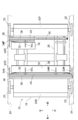
- FIG. 1 is a partial perspective view showing a three-dimensional automatic warehouse in which a transfer shuttle according to the present invention is used.
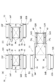
- FIG. 2 is a side view of a transfer shuttle according to the present invention.
- FIG. 3 is a plan view showing the transfer chart according to the present invention with a part cut away.
- FIG. 4 is a schematic view showing the operation of the transfer shuttle according to the present invention.
- FIG. 5 is a schematic view showing the principle of the telescopic mechanism in the transfer shuttle according to the present invention.
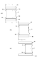
- FIG. 6 is a schematic view showing a main part of the transfer shuttle according to the present invention.
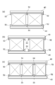
- FIG. 7 is a diagram showing several modified examples of the transfer shuttle of the present invention.
- FIG. 1 is a perspective view showing a part of a three-dimensional automatic warehouse 12 in which a transfer shuttle 10 according to the present invention is used.
- the illustrated three-dimensional automatic warehouse 12 includes at least a pair of left and right stacked racks 16L and 16R composed of a plurality of shelves 14. Between the stacked racks 16L and 16R, the transfer shuttle 10 according to the present invention for delivering the load P between the stacked racks 16L and 16R is provided for each stage or for each of a plurality of stages.
- the stacked racks 16L and 16R are configured to accommodate a shaped product, such as a bucket (plastic return box), as the load P.
- the depth of the shelf 14 in the stacked racks 16L and 16R (the length in the left-right direction shown in FIG. 1) is twice that of the conventional rack. Can be placed side by side.
- one end or both ends of the left and right stacked racks 16L and 16R are moved to transfer loads between the stacked racks 16L and 16R and an external transfer system.
- the cargo is delivered between the stacking racks 16L and 16R via the loading shuttle 10, and the transit station where the cargo is temporarily waited as necessary, and between the transit station and the external transport system.
- a lifting device for delivering the load is provided.
- the transfer shuttle 10 As shown in FIGS. 2 and 3, the transfer shuttle 10 according to the present invention used in the three-dimensional automatic warehouse 12 as described above has a traveling carriage 18 that travels horizontally between the left and right stacked racks 16L and 16R.
- Chassis portions 20F and 20B for accommodating a drive motor, a power source / control unit and the like (not shown) are provided in the front portion and the rear portion of the traveling carriage 18 along the traveling direction, respectively.
- a traveling wheel 22 is provided on each of the left and right sides of the chassis portions 20F and 20B.
- the traveling wheel 22 is disposed on a guide rail 24 extending in the horizontal direction provided at each stage of the left and right stacked racks 16L and 16R. Placed. Therefore, the traveling carriage 18 can travel back and forth along the guide rail 24 by rotating at least one of the traveling wheels 22 by the drive motor inside the chassis portion 20F or 20B.
- a load placement area 26 on which the load P is placed. More specifically, a base frame 28 is provided between the lower portions of the front and rear chassis portions 20F and 20B, and a load placement area 26 is provided by a pair of load placement plates 30 placed horizontally on the base frame 28. The bottom of is defined. Side guides 32 are formed on the outer edge of each loading plate 30 (on the side close to the adjacent chassis portions 20F and 20B), and the width between the side guides 32 is slightly larger than the width of the load P. Has been. As a result, the load P can be moved in the horizontal direction on the load placement plate 30 without causing lateral displacement or rotation. Moreover, the length (the dimension in the left-right lateral direction) of the load placement area 26 is set to a length sufficient to receive a normal load P to be handled.
- the front and rear chassis portions 20F and 20B of the traveling carriage 18 are provided with a pair of front and rear extension mechanisms 34F and 34B for loading and unloading the load P with the load placement area 26 interposed therebetween.
- the expansion / contraction mechanisms 34F and 34B are driven synchronously and used to deliver the load P between the load placement area 26 and the racks 14 of the stacked racks 16L and 16R.
- the telescopic mechanisms 34F and 34B are fixed to the inward surfaces (surfaces facing the load placement area 26) of the chassis portions 20F and 20B, and are fixed to extend in the lateral direction, that is, in the horizontal direction perpendicular to the traveling direction of the traveling carriage 18.
- the second slide rail 40 having the largest movable range.
- These rails 36, 38, 40 have substantially the same length, and are substantially the same as the lateral width of the traveling carriage 18 including the traveling wheel 22.
- FIG. 2 and FIG. 3 is a schematic view when the traveling carriage 18 travels, and project from the side surface of the traveling carriage 18. Therefore, there is no risk of hindering driving.
- FIG. 4 (a) which is a schematic view when the traveling carriage 18 travels, and project from the side surface of the traveling carriage 18. Therefore, there is no risk of hindering driving.
- the extension mechanism 34F extends so that the tip of the second slide rail 40 reaches the point beyond the load P arranged in two in the extension / contraction direction (with the necessary clearance in between).
- 34B rails 36, 38, 40 are dimensioned.
- the mechanism for expanding and contracting the expansion and contraction mechanisms 34F and 34B is a well-known mechanism using a pulley 42 and a belt (or wire) 44 as shown in FIG.
- the second slide rail 40 is also moved in the same direction along the first slide rail 38.
- the drive means for the first slide rail 38 includes a rack 46 formed on the lower edge of the first slide rail 38 over its entire length, and a timing belt 48 having teeth that mesh with the rack 46 also on the outer peripheral surface. (Endless belt with internal teeth) and a drive motor (not shown) for driving the timing belt 48.
- the timing belt 48 is wound around sprockets (see FIG. 5) provided at the left and right ends of the base frame 28, and the upper portion (the tension side portion) of the timing belt 48 is between the left and right ends of the traveling carriage 18. It extends over almost the whole area. Therefore, when the expansion / contraction mechanisms 34F and 34B are in the contracted state, almost the entire rack 46 of the first slide rail 38 is in mesh with the external teeth of the timing belt 48.
- the first slide rail 38 can be protruded to the maximum from the fixed rail 36, and the second slide rail 40 is also configured.
- the first slide rail 38 can be moved by the same distance. This makes it possible to greatly extend the moving distance of the slide rails 38 and 40 as compared with the conventional configuration in which a pinion and a rack are used as the driving means for the telescopic mechanisms 34F and 34B.
- a drive motor for driving the timing belt 48 is housed in the chassis portion 20B of the traveling carriage 18 although not shown.
- end fingers 52L and 52R for contacting and pushing the side surface of the load P are provided.
- Each end finger 52L, 52R has one end fixed to the rotating shaft of a drive motor (not shown) embedded in the second slide rail 40, and the solid line in FIG. 2 is controlled by controlling the drive motor.
- a position indicated by a solid line in FIG. 3 (a position indicated by a two-dot chain line in FIG. 2).
- the position shown in FIG. 2 is a retreat position where the end fingers 52L and 52R are sufficiently retracted from the load placement area 26, and the load P on the load placement area 26 or the load P on the shelf 14 of the stacked racks 16L and 16R. There is no interference.
- the position of FIG. 3 is a protruding position where the end fingers 52L and 52R protrude into the load placement area 26, and can contact the end face of the load P placed on the load placement area 26.
- two inner fingers 54L and 54R are further provided on the second slide rail 40 between the left and right end fingers 52L and 52R.
- These inner fingers 54L and 54R have the same shape and dimensions as the end fingers 52L and 52R, and are attached to the second slide rail 40 in exactly the same manner as the end fingers 52L and 52R.
- Each of these inner fingers 54 ⁇ / b> L and 54 ⁇ / b> R is arranged at an equal distance from the longitudinal center point of the second sliding frame 40.
- one inner finger for example, the left side 54L
- the end finger the right end finger 52R
- the slide rails 38, 40 of the telescopic mechanisms 34F, 34B are temporarily set. If the inner finger 54L is moved to the left side so that the left inner finger 54L is positioned on the left side of the left end surface of the load P and then the inner finger 54L is tilted, the shelf 14 in the right stacked rack 16R is the same as described above.
- the load P can be carried to the deepest part.
- the movement of the telescopic mechanism described in the above 0031 is performed.
- the load P can be moved in one stroke by simply using the left outer finger without using it.
- the front load P may be any of the two inner fingers 54L and 54R and the right end finger 52R. It will be understood that it is good. That is, if the telescopic mechanisms 34F and 34B are contracted from the state shown in FIG. 4B, the load P can be drawn into the transfer shuttle 10 by the left inner finger 54L. Alternatively, even if the inner fingers 54L and 54R are left in the retracted position and the right end finger 52R is in the protruding position as shown by a two-dot chain line in FIG. 4B, the end finger 52R is on the right side of the load P. Since it contacts the end face, it can be pulled into the transfer shuttle 10.
- the load P placed at the deepest part of the stacked rack 16R is transferred using the right end finger 52R.
- the load P is loaded by the same distance as the maximum moving distance S of the sliding rail 40. It cannot be moved.
- the inner finger 54 as in the present invention, as shown in FIG. 6C, the maximum moving distance of the slide rail 40 is further increased and the distance between the end finger 52 and the inner finger 54 is increased.
- the load P can be moved to a position exceeding L. Therefore, according to the configuration of the present invention, the load P can be sent to a deeper position of the stacked racks 16L and 16R, and the loads P can be arranged in two rows in the front and rear.
- FIG. 7A it may be considered that only one inner finger 54 is provided. In this configuration, two small loads P can be transferred simultaneously. Further, as shown in FIG. 7B, by arranging the two inner fingers 54 closer to the center side, two loads P can be handled at the same time as in FIG. 7A. . Furthermore, in the arrangement shown in FIG. 7C, it is possible to handle three loads P at the same time. Although not shown, when handling an irregular load P, it is conceivable to provide three or more inner fingers.
- the end fingers and the inner fingers operate independently from each other, so that the load can be conveyed in various modes.
- the load can be conveyed in various modes.
- FIGS. 1 to 3 when a small load is accommodated in the right stacking rack, three or more small loads from the deepest part of the shelf are sequentially used by using the right inner finger 54R. It can be stored. It is also possible to handle two small loads at the same time, or one small load and one medium load at the same time. That is, it is conceivable to use one load by pushing the right inner finger 54R on the right side and the other end by the left end finger 52L.
- a timing belt is used as a driving means for the telescopic mechanism, but a configuration using a hydraulic / pneumatic cylinder, a linear motor, or the like is also conceivable.
- a three-stage expansion / contraction mechanism is effective because it can use the same profile as the conventional configuration, a two-stage or four-stage expansion / contraction mechanism may be employed.
Landscapes
- Engineering & Computer Science (AREA)
- Mechanical Engineering (AREA)
- Warehouses Or Storage Devices (AREA)
Abstract
Description
図2は、本発明による移載シャトルの側面図である。
図3は、本発明による移載シャルトを一部切り欠いて示す平面図である。
図4は、本発明による移載シャトルの動作を示す概略図である。
図5は、本発明による移載シャトルにおける伸縮機構の原理を示す概略図である。
図6は、本発明による移載シャトルの要部を示す概略図である。
図7は、本発明の移載シャトルのいくつかの変形例を示す図である。
例1:中継ステーションが図4の右側、ラック収納位置が右側である場合、
外側フィンガを使用し荷を引き込む
例2:中継ステーションが図4の右側、ラック収納位置が左側である場合、
内側フィンガを使用し荷を引き込む
中継ステーションが左側に有る時も同様の動きをすることによって同じ効果が得られるのは容易に理解されよう。
Claims (7)
- 互いに平行に配置された1対の積層ラック(16L,16R)を備える立体自動倉庫(12)において用いられる、前記積層ラック(16L,16R)に対して荷(P)の受渡しを行うための移載シャトル(10)であって、
前記積層ラック(16L,16R)間にて水平方向に走行すると共に、荷(P)を載置するための荷載置エリア(26)を有する走行台車(18)と、
前記荷載置エリア(26)を挟む形で、前記走行台車(18)における走行方向に沿っての前側部分及び後側部分にそれぞれ設けられ、前記走行方向に対して直角の水平横方向に伸縮可能となるような複数のレール(36,38,40)から構成された伸縮機構(34F,34B)と、
前記複数のレール(36,38,40)のうち最も可動範囲の大きなレール(40)の両端のそれぞれに設けられ、前記荷載置エリア(26)に向かって突出する突出位置と、前記荷載置エリア(26)から待避した待避位置との間で動作可能である端部フィンガ(52L,52R)と
を備える、前記移載シャトル(10)において、
前記最も可動範囲の大きなレール(40)には、前記端部フィンガ(52L,52R)間に、前記突出位置と前記待避位置との間で動作可能である内側フィンガ(54)が設けられていることを特徴とする移載シャトル。 - 前記内側フィンガ(54L,54R)がレール片側に付き2本であることを特徴とする、請求項1に記載の移載シャトル。
- 一方の前記内側フィンガ(54L)と、この一方の内側フィンガ(54L)から、より離れている一方の前記端部フィンガ(52R)との間、及び、他方の前記内側フィンガ(54R)と他方の前記端部フィンガ(52L)との間には、それぞれ、荷Pを配置することのできる距離があることを特徴とする、請求項2に記載の移載シャトル。
- 前記端部フィンガ(52L,52R)が、当該端部フィンガ(52L,52R)に隣接する前記積層ラック(16L,16R)上に荷Pを2個分かそれ以上並べた距離を超えた位置まで移動可能となっている、請求項3に記載の移載シャトル。
- 前記伸縮機構(34F,34B)の各々が、
前記走行台車(18)に固定され、前記走行方向に直角の水平横方向に延びる固定レール(36)と、
前記固定レール(36)に、前記水平横方向と平行に、摺動可能に取り付けられた第1の摺動レール(38)と、
前記第1の摺動レール(38)に、前記水平横方向と平行に、摺動可能に取り付けられ、前記第1の摺動レール(38)と連動して該第1の摺動レール(38)の移動方向と同方向に移動する第2の摺動レール(40)と
を備え、
前記端部フィンガ(52L,52R)及び前記内側フィンガ(54)が前記第2の摺動レール(40)に設けられていることを特徴とする、請求項1~4のいずれか一項に記載の移載シャトル。 - 前記第1の摺動レール(38)の駆動手段が、前記固定レール(36)に沿って前記走行台車(18)に配置された、外周面に歯を有する無端状のベルト(48)と、前記ベルト(48)の外周面の前記歯と噛合する、前記第1の摺動レール(38)に設けられたラック(46)とを備えることを特徴とする、請求項5に記載の移載シャトル。
- 前記内側フィンガ(54)がレール片側に付き1本であることを特徴とする、請求項1に記載の移載シャトル。
Priority Applications (7)
| Application Number | Priority Date | Filing Date | Title |
|---|---|---|---|
| JP2010535531A JP5432917B2 (ja) | 2008-10-27 | 2008-10-27 | 立体自動倉庫用の移載シャトル |
| CA2741840A CA2741840C (en) | 2008-10-27 | 2008-10-27 | Transferring shuttle for automated storage/retrieval system |
| ES08877699.2T ES2523843T3 (es) | 2008-10-27 | 2008-10-27 | Sistema automático de almacenaje/recuperación |
| PCT/JP2008/069464 WO2010049987A1 (ja) | 2008-10-27 | 2008-10-27 | 立体自動倉庫用の移載シャトル |
| KR1020117010686A KR101551997B1 (ko) | 2008-10-27 | 2008-10-27 | 자동 창고용 이동셔틀 |
| US12/446,534 US8790061B2 (en) | 2008-10-27 | 2008-10-27 | Transferring shuttle for three dimensional automated warehouse |
| EP08877699.2A EP2351698B1 (en) | 2008-10-27 | 2008-10-27 | Transfer shuttle for automated warehouse |
Applications Claiming Priority (1)
| Application Number | Priority Date | Filing Date | Title |
|---|---|---|---|
| PCT/JP2008/069464 WO2010049987A1 (ja) | 2008-10-27 | 2008-10-27 | 立体自動倉庫用の移載シャトル |
Publications (1)
| Publication Number | Publication Date |
|---|---|
| WO2010049987A1 true WO2010049987A1 (ja) | 2010-05-06 |
Family
ID=42128366
Family Applications (1)
| Application Number | Title | Priority Date | Filing Date |
|---|---|---|---|
| PCT/JP2008/069464 Ceased WO2010049987A1 (ja) | 2008-10-27 | 2008-10-27 | 立体自動倉庫用の移載シャトル |
Country Status (7)
| Country | Link |
|---|---|
| US (1) | US8790061B2 (ja) |
| EP (1) | EP2351698B1 (ja) |
| JP (1) | JP5432917B2 (ja) |
| KR (1) | KR101551997B1 (ja) |
| CA (1) | CA2741840C (ja) |
| ES (1) | ES2523843T3 (ja) |
| WO (1) | WO2010049987A1 (ja) |
Cited By (24)
| Publication number | Priority date | Publication date | Assignee | Title |
|---|---|---|---|---|
| EP2433882A1 (de) | 2010-09-22 | 2012-03-28 | TGW Mechanics GmbH | Verfahren zum Einlagern von Waren sowie Vorrichtung dazu |
| WO2012044734A1 (en) | 2010-09-30 | 2012-04-05 | Dematic Accounting Services Gmbh | Shuttle for automated warehouse |
| WO2014038387A1 (ja) * | 2012-09-06 | 2014-03-13 | 村田機械株式会社 | 移載装置 |
| WO2014038308A1 (ja) * | 2012-09-05 | 2014-03-13 | 村田機械株式会社 | 移載装置 |
| DE102012220193A1 (de) * | 2012-11-06 | 2014-05-08 | Kardex Produktion Deutschland Gmbh | Lagergut-Extraktor für ein automatisches Lagersystem |
| JP2015030597A (ja) * | 2013-08-05 | 2015-02-16 | トヨタ自動車株式会社 | 移載装置、及び移載方法 |
| JP2016060624A (ja) * | 2014-09-19 | 2016-04-25 | 株式会社ダイフク | 物品搬送台車 |
| KR20160136795A (ko) * | 2015-05-21 | 2016-11-30 | 주식회사 에스에프에이 | 이송셔틀 및 이를 이용한 자동창고 시스템 |
| JP2017081753A (ja) * | 2015-10-30 | 2017-05-18 | トーヨーカネツソリューションズ株式会社 | 立体自動倉庫 |
| JP2017124934A (ja) * | 2016-01-08 | 2017-07-20 | トーヨーカネツソリューションズ株式会社 | 立体自動倉庫 |
| JP2017218251A (ja) * | 2016-06-03 | 2017-12-14 | 村田機械株式会社 | 搬送車 |
| JP2019011200A (ja) * | 2012-08-06 | 2019-01-24 | デマティック ゲーエムベーハー | 保管設備からの運搬ユニットを提供するための方法 |
| CN110027832A (zh) * | 2019-05-16 | 2019-07-19 | 山东大学 | 一种货架货笼移载穿梭车及其应用 |
| JP2019142721A (ja) * | 2012-04-09 | 2019-08-29 | オペックス コーポレーション | 品目を仕分けまたは取得する方法および装置 |
| JP2019142723A (ja) * | 2013-09-13 | 2019-08-29 | シムボティック エルエルシー | 自動保管および取出システム |
| JP2019147669A (ja) * | 2018-02-28 | 2019-09-05 | 村田機械株式会社 | サイドアーム式移載装置 |
| JP2021501731A (ja) * | 2017-11-03 | 2021-01-21 | ラブラドール システムズ インコーポレイテッド | 家庭用自律式アイテム回収及び輸送ロボットシステム |
| JP2022545523A (ja) * | 2019-09-17 | 2022-10-27 | ハイ ロボティクス カンパニー リミテッド | フォーク及び搬送用ロボット |
| JP2023107024A (ja) * | 2022-01-21 | 2023-08-02 | 村田機械株式会社 | 自動倉庫 |
| US11718473B1 (en) | 2019-09-17 | 2023-08-08 | Hai Robotics Co., Ltd. | Fork and carrying robot |
| JP2023167984A (ja) * | 2022-05-13 | 2023-11-24 | 村田機械株式会社 | 自動倉庫 |
| WO2024190084A1 (ja) * | 2023-03-10 | 2024-09-19 | 村田機械株式会社 | 自動倉庫 |
| USD1080131S1 (en) * | 2024-03-06 | 2025-06-17 | Mecalux, S.A. | Shuttle lift system |
| WO2026058710A1 (ja) * | 2024-09-11 | 2026-03-19 | 株式会社ダイフク | 移載装置(transfer device) |
Families Citing this family (153)
| Publication number | Priority date | Publication date | Assignee | Title |
|---|---|---|---|---|
| KR20110049894A (ko) | 2008-09-03 | 2011-05-12 | 디마틱 어카운팅 서비시즈 게엠베하 | 자동화된 입고/출고 시스템 |
| US9321591B2 (en) | 2009-04-10 | 2016-04-26 | Symbotic, LLC | Autonomous transports for storage and retrieval systems |
| US8594835B2 (en) | 2009-04-10 | 2013-11-26 | Symbotic, LLC | Control system for storage and retrieval systems |
| AT508361B1 (de) * | 2009-08-17 | 2011-01-15 | Knapp Ag | Lagersystem |
| EP2536649B1 (en) | 2010-02-19 | 2016-05-25 | Dematic Corp. | Goods-to-person picking station and picking method |
| US9561905B2 (en) | 2010-12-15 | 2017-02-07 | Symbotic, LLC | Autonomous transport vehicle |
| US9187244B2 (en) | 2010-12-15 | 2015-11-17 | Symbotic, LLC | BOT payload alignment and sensing |
| US9499338B2 (en) | 2010-12-15 | 2016-11-22 | Symbotic, LLC | Automated bot transfer arm drive system |
| US8696010B2 (en) | 2010-12-15 | 2014-04-15 | Symbotic, LLC | Suspension system for autonomous transports |
| US11078017B2 (en) | 2010-12-15 | 2021-08-03 | Symbotic Llc | Automated bot with transfer arm |
| US8965619B2 (en) | 2010-12-15 | 2015-02-24 | Symbotic, LLC | Bot having high speed stability |
| DE102011010544A1 (de) * | 2011-02-07 | 2012-08-09 | Eisenmann Ag | Tragbahnförderer und Förderanlage mit einem solchen |
| AT511162A1 (de) | 2011-02-08 | 2012-09-15 | Tgw Mechanics Gmbh | Regallagersystem |
| AT511140B1 (de) | 2011-02-08 | 2014-06-15 | Tgw Mechanics Gmbh | Regallagersystem und verfahren zum betreiben desselben |
| AT511138B1 (de) | 2011-02-08 | 2015-01-15 | Tgw Mechanics Gmbh | Einebenenregalbediengerät zum ein- bzw. auslagern von ladegütern in ein bzw. aus einem regallager |
| AT511137B1 (de) | 2011-02-08 | 2020-10-15 | Tgw Mechanics Gmbh | Regallagersystem und verfahren zum betreiben desselben |
| EP2683635A2 (en) * | 2011-03-11 | 2014-01-15 | Subramanian Venkatraman | Multi level automated storage and handling system for containers and bulky objects |
| FI123784B (fi) * | 2011-03-25 | 2013-10-31 | Konecranes Oyj | Järjestely kuormauselimen heilahduksen vaimentamiseksi nosturissa |
| US9056719B2 (en) * | 2011-03-29 | 2015-06-16 | Murata Machinery, Ltd. | Automatic storage system |
| CN103459273B (zh) | 2011-04-04 | 2015-06-03 | 德马泰克财务服务有限公司 | 用于轨道导引式车辆的通道紧急制动器 |
| AT511623B1 (de) | 2011-07-08 | 2016-01-15 | Tgw Mechanics Gmbh | Regallagersystem |
| AT511641A3 (de) | 2011-07-08 | 2013-07-15 | Tgw Mechanics Gmbh | Lastaufnahmemittel zum ein- und auslagern von ladegütern |
| AT14347U1 (de) * | 2011-07-22 | 2015-09-15 | Tgw Mechanics Gmbh | Förderfahrzeug, insbesondere selbstfahrendes Shuttle, für ein Regallager |
| AT511759A3 (de) | 2011-07-22 | 2013-07-15 | Tgw Mechanics Gmbh | Förderfahrzeug, insbesondere selbstfahrendes shuttle, für ein regallager |
| DE102011084551A1 (de) * | 2011-10-14 | 2013-04-18 | Krones Aktiengesellschaft | Regalbediengerät und Kommissionierlager |
| BE1020361A3 (nl) * | 2011-12-23 | 2013-08-06 | Alvey Nv | Pick-en-place inrichting. |
| ES2492530T3 (es) * | 2012-01-30 | 2014-09-09 | Carefusion Germany 326 Gmbh | Procedimiento para recuperar envases de medicamentos |
| CN102616518B (zh) * | 2012-03-29 | 2013-12-11 | 缪慰时 | 用于高密度自动仓库中的遥控穿梭车 |
| DE102012107438A1 (de) | 2012-08-14 | 2014-03-27 | Dematic Accounting Services Gmbh | Verfahren zur Herstellung einer Zahnstange |
| US9701471B2 (en) * | 2012-08-31 | 2017-07-11 | Murata Machinery, Ltd. | Transfer device |
| CN104428219B (zh) * | 2012-09-05 | 2016-04-27 | 村田机械株式会社 | 移载装置 |
| DE102012017985A1 (de) * | 2012-09-12 | 2014-04-03 | Servus Intralogistics Gmbh | Transportroboter mit Längsförderer für die Handhabung von Behältern |
| KR101422685B1 (ko) * | 2012-12-28 | 2014-07-23 | 주식회사 유일에프에이 | 랙용 레일-운반대차 어셈블리 |
| US9122566B2 (en) | 2013-03-08 | 2015-09-01 | Bastian Solutions, Llc | Robotic material handling system |
| US20140271069A1 (en) * | 2013-03-14 | 2014-09-18 | Illinois Tool Works Inc. | Storage Carts |
| US9067740B2 (en) * | 2013-03-15 | 2015-06-30 | Intelligrated Headquarters, Llc | Remotely driven shuttle car |
| US9139363B2 (en) | 2013-03-15 | 2015-09-22 | John Lert | Automated system for transporting payloads |
| EP2815976A1 (en) * | 2013-06-17 | 2014-12-24 | Airbus Operations GmbH | Vehicle comprising a transport arrangement |
| DE102013011860A1 (de) | 2013-07-16 | 2015-01-22 | Servus Intralogistics Gmbh | Transportroboter mit Einzugsvorrichtung für Transportgüter |
| DE102013107873A1 (de) * | 2013-07-23 | 2015-01-29 | SSI Schäfer PEEM GmbH | Förderfahrzeug sowie Basisgestell und Baukastensystem für Förderfahrzeug |
| DE102013013274A1 (de) * | 2013-08-09 | 2015-02-12 | Servus Intralogistics Gmbh | Transportroboter mit Hubeinheit für Transportgüter |
| EP2862817B1 (en) * | 2013-10-15 | 2015-08-19 | Pharmathek S.r.L. | Unit and procedure for automated transfer of box elements |
| SE538974C2 (sv) * | 2013-12-03 | 2017-03-07 | Texo Application Ab | Nödstoppsanordning för skyttel, samt lagersystem med skenor och skyttel |
| EP2952454A1 (en) * | 2014-06-02 | 2015-12-09 | Dematic Systems GmbH | Method of extending the load handling range of an automated storage/retrieval system |
| WO2016007330A1 (en) | 2014-07-08 | 2016-01-14 | Dematic Corp. | Lift configuration for carriage-based warehouse |
| NL2013200B1 (nl) * | 2014-07-16 | 2016-07-14 | Vanderlande Ind Bv | Systeem voor het opslaan van producthouders. |
| AT14533U1 (de) * | 2014-08-05 | 2016-01-15 | Stickler Immobilien Gmbh | Shuttle für ein Lager |
| MX2017002158A (es) | 2014-08-20 | 2017-08-10 | Dematic Corp | Coincidencia de velocidad dinamica para manejo de material. |
| AT516231B1 (de) | 2014-09-05 | 2016-09-15 | Tgw Mechanics Gmbh | Automatisiertes Regallagersystem und Verfahren zum sicheren Betreiben desselben |
| DK3193807T3 (en) * | 2014-09-18 | 2021-10-18 | Ideassociates Iom Ltd | A wheeled transportation device |
| US9409728B2 (en) | 2014-11-03 | 2016-08-09 | Bastian Solutions, Llc | Automated case flow buffer |
| CN107428463B (zh) * | 2014-12-10 | 2020-09-11 | 瑞仕格赢麦迪科有限公司 | 负载收纳装置 |
| US9884719B2 (en) | 2014-12-12 | 2018-02-06 | Symbotic, LLC | Storage and retrieval system |
| JP6398680B2 (ja) * | 2014-12-12 | 2018-10-03 | 村田機械株式会社 | サイドアーム式移載装置 |
| AT516633A1 (de) | 2014-12-18 | 2016-07-15 | Tgw Logistics Group Gmbh | Lageranordnung mit verbessertem Energieausgleich zwischen Regalbediengeräten |
| US10294027B2 (en) * | 2015-01-09 | 2019-05-21 | Carefusion Germany 326 Gmbh | Operating device for an order-picking apparatus |
| US11893533B2 (en) | 2015-01-16 | 2024-02-06 | Symbotic Llc | Storage and retrieval system |
| US12280953B2 (en) | 2015-01-16 | 2025-04-22 | Symbotic Llc | Storage and retrieval system |
| US10974897B2 (en) | 2015-01-16 | 2021-04-13 | Symbotic Llc | Storage and retrieval system |
| US10214355B2 (en) | 2015-01-16 | 2019-02-26 | Symbotic, LLC | Storage and retrieval system |
| US10521767B2 (en) | 2015-01-16 | 2019-12-31 | Symbotic, LLC | Storage and retrieval system |
| US10102496B2 (en) | 2015-01-16 | 2018-10-16 | Symbotic, LLC | Storage and retrieval system |
| US9856083B2 (en) | 2015-01-16 | 2018-01-02 | Symbotic, LLC | Storage and retrieval system |
| US11254502B2 (en) | 2015-01-16 | 2022-02-22 | Symbotic Llc | Storage and retrieval system |
| US9850079B2 (en) | 2015-01-23 | 2017-12-26 | Symbotic, LLC | Storage and retrieval system transport vehicle |
| AT516410B1 (de) | 2015-04-22 | 2016-05-15 | Tgw Mechanics Gmbh | Verfahren zum Einlagern von Stückgütern in ein Lagerregal und Lagersystem |
| ES2926468T3 (es) | 2015-05-29 | 2022-10-26 | Tgw Mechanics Gmbh | Sistema de almacenamiento |
| US11142398B2 (en) | 2015-06-02 | 2021-10-12 | Alert Innovation Inc. | Order fulfillment system |
| EP3650375A1 (en) | 2015-06-02 | 2020-05-13 | Alert Innovation Inc. | Storage and retrieval system |
| US11203486B2 (en) | 2015-06-02 | 2021-12-21 | Alert Innovation Inc. | Order fulfillment system |
| KR101725644B1 (ko) | 2015-07-28 | 2017-04-11 | 한국항공대학교산학협력단 | 자동화물 시스템용 이동셔틀 |
| KR101662955B1 (ko) | 2015-07-28 | 2016-10-05 | 한국항공대학교산학협력단 | 자동화물 시스템용 이동셔틀 |
| CA2938850C (en) | 2015-08-12 | 2022-02-22 | Axium Robotic and Automation ULC | System and method for palletizing |
| EP3166058A1 (en) | 2015-11-09 | 2017-05-10 | Dematic Systems GmbH | Method of fulfilling orders in a warehouse with an order fulfillment area |
| CN105416945B (zh) * | 2015-12-02 | 2017-09-08 | 国网浙江省电力公司湖州供电公司 | 货物取放装置及采用该装置的货物搬运设备 |
| EP3182348A1 (en) | 2015-12-17 | 2017-06-21 | Dematic Systems GmbH | Method of order fulfilling by making storage units available from a storage facility in a desired sequence at a picking station |
| USD857072S1 (en) | 2016-01-22 | 2019-08-20 | Symbotic, LLC | Automated guided vehicle |
| EP3272679B1 (en) | 2016-07-19 | 2020-10-21 | Dematic GmbH | Automatically centring load support for shuttle vehicles having a variable receiving width |
| DE112017004045T5 (de) * | 2016-09-26 | 2019-05-23 | Intelligrated Headquarters, Llc | Vollständig validierter materialtransport mit pendelbehälterliefersystem |
| WO2018094286A1 (en) | 2016-11-17 | 2018-05-24 | Alert Innovation Inc. | Automated-service retail system and method |
| CA3302758A1 (en) | 2016-11-29 | 2026-03-31 | Symbotic Llc | Automated retail supply chain and inventory management system |
| JP2020504066A (ja) | 2017-01-10 | 2020-02-06 | アラート イノヴェイション インコーポレイテッド | 交換可能自動移動ロボットを備えた自動ストア |
| JP7478320B2 (ja) | 2017-02-24 | 2024-05-07 | ウォルマート アポロ リミテッド ライアビリティ カンパニー | 在庫管理システムおよび方法 |
| CN110636981B (zh) | 2017-03-08 | 2021-10-26 | 雷勃美国公司 | 包裹分拣传送模块和系统及其方法 |
| US10532894B2 (en) | 2017-03-10 | 2020-01-14 | Regal Beloit America, Inc. | Modular transfer units, systems, and methods |
| AU2018248877B2 (en) | 2017-04-07 | 2023-08-17 | Dematic Gmbh | Method and system for transporting units within a storage facility |
| CN106882529A (zh) * | 2017-04-14 | 2017-06-23 | 杭州南江机器人股份有限公司 | 一种agv用对接机构及agv |
| US10744894B2 (en) | 2017-05-08 | 2020-08-18 | Bastian Solutions, Llc | Charging system for an autonomous mobile unit |
| US10322505B2 (en) * | 2017-07-20 | 2019-06-18 | Becton Dickinson Rowa Germany Gmbh | Controller for a commissioning device |
| US11117743B2 (en) | 2017-09-28 | 2021-09-14 | Symbotic Llc | Storage and retrieval system |
| FR3072371A1 (fr) * | 2017-10-12 | 2019-04-19 | Exotec Solutions | Systeme de stockage et de transport d'objets entreposes dans des rayonnages d'un entrepot |
| US12330870B2 (en) | 2017-11-14 | 2025-06-17 | Hai Robotics Co., Ltd. | Handling robot |
| US12103771B2 (en) * | 2017-11-14 | 2024-10-01 | Hai Robotics Co., Ltd. | Handling robot |
| US12006143B2 (en) | 2017-11-14 | 2024-06-11 | Hai Robotics Co., Ltd. | Handling robot |
| DE202018006724U1 (de) * | 2017-11-14 | 2022-06-02 | Hai Robotics Co., Ltd. | Handhabungsroboter |
| US11465840B2 (en) | 2017-11-14 | 2022-10-11 | Hai Robotics Co., Ltd. | Handling robot |
| US11396424B2 (en) | 2017-11-14 | 2022-07-26 | Hai Robotics Co., Ltd. | Handling robot |
| WO2019104095A2 (en) | 2017-11-22 | 2019-05-31 | Regal Beloit America, Inc. | Modular sortation units, systems, and methods |
| US10864641B2 (en) | 2017-12-01 | 2020-12-15 | Bastian Solutions, Llc | End effector |
| KR101917978B1 (ko) | 2018-02-27 | 2018-11-12 | 이기현 | 트레이 이송기 |
| US11390504B2 (en) | 2018-03-20 | 2022-07-19 | Bastian Solutions, Llc | Lift mechanism for robotic shuttle system |
| CA3117483A1 (en) | 2018-03-20 | 2019-09-26 | Bastian Solutions, Llc | Robotic shuttle system |
| KR102466772B1 (ko) * | 2018-05-02 | 2022-11-14 | 주식회사 엘지화학 | 컨베이어 벨트 |
| NO344750B1 (en) * | 2018-06-12 | 2020-04-06 | Autostore Tech As | Unloading arrangement and unloading station, as well as method of unloading an item from a storage container |
| US10435252B1 (en) | 2018-10-08 | 2019-10-08 | Becton Dickinson Rowa Germany Gmbh | Operating device for placing or retrieving bottle-like piece goods |
| KR102078227B1 (ko) * | 2018-11-26 | 2020-02-19 | (주)랩투마켓 | 적재함 교체가 가능한 모듈형 셔틀 구조 |
| KR102147394B1 (ko) * | 2018-11-26 | 2020-08-24 | (주)랩투마켓 | 길이조절 암을 구비한 개량형 셔틀 구조 |
| KR102142194B1 (ko) * | 2018-11-26 | 2020-08-06 | (주)일양엔지니어링 | 화물 이송용 셔틀 |
| KR102078228B1 (ko) * | 2018-11-26 | 2020-02-19 | (주)랩투마켓 | 적재함 리프팅이 가능한 모듈형 셔틀 구조 |
| ES2956870T3 (es) | 2018-11-28 | 2023-12-29 | Autostore Tech As | Contenedor de almacenamiento para sistema de almacenamiento y recuperación automatizado |
| US11542135B2 (en) | 2019-02-01 | 2023-01-03 | Hai Robotics Co., Ltd. | Handling robot |
| US11597598B2 (en) | 2019-02-01 | 2023-03-07 | Hai Robotics Co., Ltd. | Handling robot |
| JP7063295B2 (ja) * | 2019-03-22 | 2022-05-09 | 株式会社ダイフク | 物品搬送車 |
| DE102019204762B4 (de) * | 2019-04-03 | 2024-11-07 | Audi Ag | Lastaufnahmevorrichtung für ein automatisches Lager |
| USD898092S1 (en) * | 2019-06-03 | 2020-10-06 | Storage Management Sysem (Pty) Ltd. | Bogie for a warehousing shuttle |
| KR102247616B1 (ko) * | 2019-06-10 | 2021-05-04 | (주)엑시스 소프트웨어 엔지니어링 | 로더 |
| KR102247613B1 (ko) * | 2019-06-10 | 2021-05-04 | (주)엑시스 소프트웨어 엔지니어링 | 로더 |
| DE102019209097A1 (de) * | 2019-06-24 | 2020-12-24 | Gebhardt Fördertechnik GmbH | Vorrichtung und Verfahren zum Transport von Ladegütern in einem Lager- und Entnahmesystem |
| CN111776559B (zh) * | 2019-09-09 | 2021-10-15 | 北京京东乾石科技有限公司 | 仓库穿梭车 |
| KR102336620B1 (ko) | 2019-09-23 | 2021-12-09 | 주식회사 티에스피지 | 주행대차용 텔레스코픽 포크장치 |
| JP7429289B2 (ja) * | 2019-10-23 | 2024-02-07 | シャンハイ クイックトロン インテリジェント テクノロジー カンパニー リミテッド | 伸縮装置及び搬送ロボット |
| US11407587B1 (en) * | 2019-11-04 | 2022-08-09 | Amazon Technologies, Inc. | Automated container retrieval and delivery systems |
| CN113401548B (zh) | 2020-03-16 | 2023-07-11 | 因特利格雷特总部有限责任公司 | 用于多深度存放架的自动化穿梭车系统 |
| IT202000005632A1 (it) * | 2020-03-17 | 2021-09-17 | Automha S P A | Dispositivo di prelievo e/o deposito di articoli per magazzini automatici. |
| WO2021220686A1 (ja) * | 2020-04-30 | 2021-11-04 | 村田機械株式会社 | 走行台車、及び、自動倉庫 |
| DE102020111980A1 (de) * | 2020-05-04 | 2021-11-04 | Rocket Solution Gmbh | Shuttle und Regalsystem |
| US12172837B2 (en) | 2020-05-27 | 2024-12-24 | Dematic Corp. | Robotic automated storage and retrieval system and method of storing articles |
| USD1018617S1 (en) * | 2020-08-13 | 2024-03-19 | Opex Corporation | Automated storage and retrieval vehicle |
| EP3960656A1 (en) | 2020-08-24 | 2022-03-02 | Dematic GmbH | System for storage of goods carriers |
| DE102020213046A1 (de) | 2020-10-15 | 2022-04-21 | Gebhardt Fördertechnik GmbH | Lager- und Entnahmesystem sowie ein Lagerregal |
| US11912511B2 (en) * | 2020-12-09 | 2024-02-27 | Becton Dickinson Rowa Germany Gmbh | Gripper and transport system for a picking device |
| USD982047S1 (en) * | 2020-12-21 | 2023-03-28 | Beijing Jingdong Qianshi Technology Co., Ltd. | Logistics robot |
| CN113233064A (zh) * | 2021-01-27 | 2021-08-10 | 威海天润智能科技有限公司 | 堆栈立仓 |
| AT524823B1 (de) | 2021-02-26 | 2023-08-15 | Tgw Mechanics Gmbh | Verfahren und Regallagersystem mit erhöhter Sicherheit beim Anhalten eines Regalbediengeräts |
| EP4341175A1 (en) * | 2021-05-17 | 2024-03-27 | Ocado Innovation Limited | Mechanical handling apparatus |
| KR102339212B1 (ko) * | 2021-05-20 | 2021-12-14 | 주식회사 에이피씨소프트 | 자동 창고용 이송 로봇 |
| TWI837875B (zh) * | 2021-10-12 | 2024-04-01 | 美商靈巧公司 | 機器人堆棧推進器系統、用於將一有效負載裝載至一機器人工作空間或以其他方式裝載至一機器人堆棧移動器系統之方法、及體現於一非暫時性電腦可讀媒體中之電腦程式產品 |
| USD1104856S1 (en) * | 2021-10-20 | 2025-12-09 | Intelligrated Headquarters, Llc | Shuttle car |
| JP7501496B2 (ja) * | 2021-11-09 | 2024-06-18 | 株式会社ダイフク | 移載装置 |
| CN114476468A (zh) * | 2022-02-28 | 2022-05-13 | 北京京东乾石科技有限公司 | 穿梭车以及穿梭车存取系统 |
| CN114803242B (zh) * | 2022-04-01 | 2024-01-16 | 萨驰智能装备股份有限公司 | 一种物料输送系统及控制方法 |
| CZ2022164A3 (cs) * | 2022-04-21 | 2023-11-01 | RUR Robotics s.r.o. | Skladovací systém, vozík pro skladovací systém a regálová konstrukce |
| CN114916694B (zh) * | 2022-04-29 | 2023-05-26 | 成都琅思智能设备有限公司 | 烟叶自动化批量运输晾晒系统及晾晒、下架方法 |
| EP4310026A1 (de) * | 2022-07-22 | 2024-01-24 | Goya Systec S.R.L. | Transportfahrzeug für automatisierte lager |
| JP2024030797A (ja) * | 2022-08-25 | 2024-03-07 | 株式会社椿本チエイン | 移載システム |
| TWM636964U (zh) * | 2022-10-05 | 2023-01-21 | 張榮傑 | 自動倉儲台車搬運裝置 |
| USD1101012S1 (en) | 2023-02-21 | 2025-11-04 | Intelligrated Headquarters, Llc | Shuttle car |
| US12528648B1 (en) * | 2023-03-13 | 2026-01-20 | Amazon Technologies, Inc. | Systems and methods for payload shuttles for efficiently loading and unloading containers |
| EP4683871A1 (de) | 2023-03-21 | 2026-01-28 | TGW Logistics GmbH | Transportfahrzeug zum transport von stückgut und verfahren zur herstellung eines abdeckungselementes hierfür |
| AT527164B1 (de) | 2023-04-21 | 2025-05-15 | Tgw Mechanics Gmbh | Transportfahrzeug zum Transport und Verfahren zur Handhabung von Stückgut in einem Lagersystem |
| KR20240157142A (ko) * | 2023-04-24 | 2024-11-01 | 엘지전자 주식회사 | 로봇 시스템 |
| GB202310834D0 (en) * | 2023-07-14 | 2023-08-30 | Richmond Design And Marketing Ltd | Apparatus, systems, and vehicles for airside container loading and unloading |
| CN119706162B (zh) * | 2025-02-26 | 2025-08-01 | 山东深蓝机器股份有限公司 | 一种物流穿梭车 |
Citations (5)
| Publication number | Priority date | Publication date | Assignee | Title |
|---|---|---|---|---|
| JPH08324721A (ja) | 1995-05-31 | 1996-12-10 | Itoki Crebio Corp | 自動倉庫における移動台車の搬出入装置 |
| JPH1179321A (ja) * | 1997-09-10 | 1999-03-23 | Toyota Autom Loom Works Ltd | スタッカクレーン用移載装置の制御装置 |
| JP2000211706A (ja) * | 1999-01-19 | 2000-08-02 | Daifuku Co Ltd | 物品移載装置及び物品保管設備 |
| JP2003048604A (ja) * | 2001-08-01 | 2003-02-21 | Nippon Yusoki Co Ltd | 自動倉庫システム |
| JP2006096522A (ja) * | 2004-09-29 | 2006-04-13 | Daido Steel Co Ltd | 立体倉庫 |
Family Cites Families (22)
| Publication number | Priority date | Publication date | Assignee | Title |
|---|---|---|---|---|
| JPS5332586B2 (ja) * | 1973-01-19 | 1978-09-08 | ||
| FI76039C (fi) * | 1986-09-10 | 1988-09-09 | Seppo Kalervo Suominen | Foerfarande och transportvagn foer hindrande av kumulering av fel vid kolliparkering i lager av sekvenstyp. |
| JPS63165205A (ja) | 1986-12-25 | 1988-07-08 | Itoki Kosakusho Co Ltd | 自動保管検索装置 |
| JPH08175620A (ja) | 1994-12-27 | 1996-07-09 | Itoki Crebio Corp | 自動保管検索装置における搬出入機構 |
| JP3335786B2 (ja) | 1994-12-27 | 2002-10-21 | 株式会社イトーキクレビオ | 自動保管検索装置における搬出入機構 |
| EP0733563A1 (en) * | 1995-03-22 | 1996-09-25 | Toyokanetsu Kabushiki Kaisha | Merchandise handling equipment and merchandise storage equipment |
| JP3369392B2 (ja) | 1996-03-08 | 2003-01-20 | 株式会社ダイフク | 物品保管設備 |
| US5839873A (en) * | 1996-03-28 | 1998-11-24 | Hk Systems, Inc. | Storage and retrieval machine with pre-tensioned shuttle guides |
| US6619902B1 (en) * | 1997-02-11 | 2003-09-16 | Stein & Associates, P.C. | Automated storage and retrieval system and indexing/insertion extraction mechanism therefor |
| JPH10297712A (ja) | 1997-04-25 | 1998-11-10 | Murata Mach Ltd | 物品の貯留装置 |
| IT1294287B1 (it) * | 1997-07-30 | 1999-03-24 | Fata Automation | Magazzino a celle con carri di trasporto a movimentazione idropneumatica |
| WO2003019425A1 (de) | 2001-08-23 | 2003-03-06 | Tgw Transportgeräte Gmbh & Co.Kg | Zwischenlager für identifizierte waren und verfahren zur weitergabe von bestellten waren |
| US6923612B2 (en) | 2002-03-29 | 2005-08-02 | TGW Transportgeräte GmbH & Co. KG | Load-handling system and telescopic arm therefor |
| JP3910129B2 (ja) | 2002-09-30 | 2007-04-25 | 株式会社イトーキ | 自動倉庫 |
| DE202004004620U1 (de) * | 2003-03-28 | 2004-08-12 | TGW-Transportgeräte-Ges.m.b.H. & Co. KG | Lagersystem |
| AT500228B1 (de) * | 2003-05-20 | 2007-07-15 | Tgw Transportgeraete Gmbh | Teleskopschubarm, insbesondere für eine lastaufnahmevorrichtung |
| US7735631B2 (en) * | 2003-09-03 | 2010-06-15 | Siemens Aktiengesellschaft | Mail processing system and method of delivering articles to delivery locations therein |
| DE102005009695A1 (de) * | 2005-02-28 | 2006-08-31 | Keuro Besitz Gmbh & Co Edv-Dienstleistungs Kg | Regallager und Verfahren zum Umlagern von Lagergut bei einem Regallager |
| EP1772400A1 (de) * | 2005-10-06 | 2007-04-11 | Stöcklin Logistik AG | Lastaufnahmevorrichtung mit Teleskoparmen mit verstellbaren Mitnehmern |
| US7686560B2 (en) * | 2005-12-08 | 2010-03-30 | Conestoga Cold Storage | Rack, conveyor and shuttle automated pick system |
| JP4415397B2 (ja) | 2007-09-03 | 2010-02-17 | 村田機械株式会社 | スタッカークレーン |
| KR20110049894A (ko) | 2008-09-03 | 2011-05-12 | 디마틱 어카운팅 서비시즈 게엠베하 | 자동화된 입고/출고 시스템 |
-
2008
- 2008-10-27 JP JP2010535531A patent/JP5432917B2/ja active Active
- 2008-10-27 CA CA2741840A patent/CA2741840C/en active Active
- 2008-10-27 EP EP08877699.2A patent/EP2351698B1/en active Active
- 2008-10-27 ES ES08877699.2T patent/ES2523843T3/es active Active
- 2008-10-27 KR KR1020117010686A patent/KR101551997B1/ko active Active
- 2008-10-27 WO PCT/JP2008/069464 patent/WO2010049987A1/ja not_active Ceased
- 2008-10-27 US US12/446,534 patent/US8790061B2/en active Active
Patent Citations (5)
| Publication number | Priority date | Publication date | Assignee | Title |
|---|---|---|---|---|
| JPH08324721A (ja) | 1995-05-31 | 1996-12-10 | Itoki Crebio Corp | 自動倉庫における移動台車の搬出入装置 |
| JPH1179321A (ja) * | 1997-09-10 | 1999-03-23 | Toyota Autom Loom Works Ltd | スタッカクレーン用移載装置の制御装置 |
| JP2000211706A (ja) * | 1999-01-19 | 2000-08-02 | Daifuku Co Ltd | 物品移載装置及び物品保管設備 |
| JP2003048604A (ja) * | 2001-08-01 | 2003-02-21 | Nippon Yusoki Co Ltd | 自動倉庫システム |
| JP2006096522A (ja) * | 2004-09-29 | 2006-04-13 | Daido Steel Co Ltd | 立体倉庫 |
Non-Patent Citations (1)
| Title |
|---|
| See also references of EP2351698A1 |
Cited By (45)
| Publication number | Priority date | Publication date | Assignee | Title |
|---|---|---|---|---|
| EP2433882A1 (de) | 2010-09-22 | 2012-03-28 | TGW Mechanics GmbH | Verfahren zum Einlagern von Waren sowie Vorrichtung dazu |
| AT510537A1 (de) * | 2010-09-22 | 2012-04-15 | Tgw Mechanics Gmbh | Verfahren zum einlagern von waren sowie vorrichtung dazu |
| WO2012044734A1 (en) | 2010-09-30 | 2012-04-05 | Dematic Accounting Services Gmbh | Shuttle for automated warehouse |
| EP2759494A1 (en) | 2010-09-30 | 2014-07-30 | Dematic Accounting Services GmbH | Shuttle for automated warehouse |
| US12234093B2 (en) | 2012-04-09 | 2025-02-25 | Opex Corporation | Method and apparatus for sorting or retrieving items |
| JP2019142721A (ja) * | 2012-04-09 | 2019-08-29 | オペックス コーポレーション | 品目を仕分けまたは取得する方法および装置 |
| JP2019011200A (ja) * | 2012-08-06 | 2019-01-24 | デマティック ゲーエムベーハー | 保管設備からの運搬ユニットを提供するための方法 |
| WO2014038308A1 (ja) * | 2012-09-05 | 2014-03-13 | 村田機械株式会社 | 移載装置 |
| JPWO2014038308A1 (ja) * | 2012-09-05 | 2016-08-08 | 村田機械株式会社 | 移載装置 |
| TWI602767B (zh) * | 2012-09-05 | 2017-10-21 | Murata Machinery Ltd | Transfer device |
| CN104428218B (zh) * | 2012-09-05 | 2015-11-25 | 村田机械株式会社 | 移载装置 |
| KR20150038576A (ko) * | 2012-09-06 | 2015-04-08 | 무라다기카이가부시끼가이샤 | 이송 장치 |
| JPWO2014038387A1 (ja) * | 2012-09-06 | 2016-08-08 | 村田機械株式会社 | 移載装置 |
| WO2014038387A1 (ja) * | 2012-09-06 | 2014-03-13 | 村田機械株式会社 | 移載装置 |
| KR101699771B1 (ko) | 2012-09-06 | 2017-01-25 | 무라다기카이가부시끼가이샤 | 이송 장치 |
| DE102012220193A1 (de) * | 2012-11-06 | 2014-05-08 | Kardex Produktion Deutschland Gmbh | Lagergut-Extraktor für ein automatisches Lagersystem |
| JP2015030597A (ja) * | 2013-08-05 | 2015-02-16 | トヨタ自動車株式会社 | 移載装置、及び移載方法 |
| US9375846B2 (en) | 2013-08-05 | 2016-06-28 | Toyota Jidosha Kabushiki Kaisha | Transfer apparatus and transfer method |
| JP2019142723A (ja) * | 2013-09-13 | 2019-08-29 | シムボティック エルエルシー | 自動保管および取出システム |
| JP2016060624A (ja) * | 2014-09-19 | 2016-04-25 | 株式会社ダイフク | 物品搬送台車 |
| KR101717447B1 (ko) * | 2015-05-21 | 2017-03-20 | 주식회사 에스에프에이 | 이송셔틀 및 이를 이용한 자동창고 시스템 |
| KR20160136795A (ko) * | 2015-05-21 | 2016-11-30 | 주식회사 에스에프에이 | 이송셔틀 및 이를 이용한 자동창고 시스템 |
| JP7004424B2 (ja) | 2015-10-30 | 2022-01-21 | トーヨーカネツ株式会社 | 立体自動倉庫 |
| JP2017081753A (ja) * | 2015-10-30 | 2017-05-18 | トーヨーカネツソリューションズ株式会社 | 立体自動倉庫 |
| JP2017124934A (ja) * | 2016-01-08 | 2017-07-20 | トーヨーカネツソリューションズ株式会社 | 立体自動倉庫 |
| JP7206454B2 (ja) | 2016-01-08 | 2023-01-18 | トーヨーカネツ株式会社 | 立体自動倉庫 |
| JP2017218251A (ja) * | 2016-06-03 | 2017-12-14 | 村田機械株式会社 | 搬送車 |
| JP2021501731A (ja) * | 2017-11-03 | 2021-01-21 | ラブラドール システムズ インコーポレイテッド | 家庭用自律式アイテム回収及び輸送ロボットシステム |
| JP7229563B2 (ja) | 2017-11-03 | 2023-02-28 | ラブラドール システムズ インコーポレイテッド | 家庭用自律式アイテム回収及び輸送ロボットシステム |
| JP2019147669A (ja) * | 2018-02-28 | 2019-09-05 | 村田機械株式会社 | サイドアーム式移載装置 |
| CN110027832A (zh) * | 2019-05-16 | 2019-07-19 | 山东大学 | 一种货架货笼移载穿梭车及其应用 |
| JP7561940B2 (ja) | 2019-09-17 | 2024-10-04 | ハイ ロボティクス カンパニー リミテッド | フォーク及び搬送用ロボット |
| US12509296B2 (en) | 2019-09-17 | 2025-12-30 | Hai Robotics Co., Ltd. | Fork and carrying robot |
| JP7360543B2 (ja) | 2019-09-17 | 2023-10-12 | ハイ ロボティクス カンパニー リミテッド | フォーク及び搬送用ロボット |
| US11807451B2 (en) | 2019-09-17 | 2023-11-07 | Hai Robotics Co., Ltd. | Fork and carrying robot |
| JP2023164756A (ja) * | 2019-09-17 | 2023-11-10 | ハイ ロボティクス カンパニー リミテッド | フォーク及び搬送用ロボット |
| US12054339B2 (en) | 2019-09-17 | 2024-08-06 | Hai Robotics Co., Ltd. | Fork and carrying robot |
| JP2022545523A (ja) * | 2019-09-17 | 2022-10-27 | ハイ ロボティクス カンパニー リミテッド | フォーク及び搬送用ロボット |
| US11718473B1 (en) | 2019-09-17 | 2023-08-08 | Hai Robotics Co., Ltd. | Fork and carrying robot |
| JP7515790B2 (ja) | 2022-01-21 | 2024-07-16 | 村田機械株式会社 | 自動倉庫 |
| JP2023107024A (ja) * | 2022-01-21 | 2023-08-02 | 村田機械株式会社 | 自動倉庫 |
| JP2023167984A (ja) * | 2022-05-13 | 2023-11-24 | 村田機械株式会社 | 自動倉庫 |
| WO2024190084A1 (ja) * | 2023-03-10 | 2024-09-19 | 村田機械株式会社 | 自動倉庫 |
| USD1080131S1 (en) * | 2024-03-06 | 2025-06-17 | Mecalux, S.A. | Shuttle lift system |
| WO2026058710A1 (ja) * | 2024-09-11 | 2026-03-19 | 株式会社ダイフク | 移載装置(transfer device) |
Also Published As
| Publication number | Publication date |
|---|---|
| EP2351698A4 (en) | 2013-01-16 |
| JP5432917B2 (ja) | 2014-03-05 |
| US20110008138A1 (en) | 2011-01-13 |
| US8790061B2 (en) | 2014-07-29 |
| EP2351698A1 (en) | 2011-08-03 |
| KR20110074901A (ko) | 2011-07-04 |
| CA2741840A1 (en) | 2010-05-06 |
| KR101551997B1 (ko) | 2015-09-09 |
| JPWO2010049987A1 (ja) | 2012-03-22 |
| ES2523843T3 (es) | 2014-12-02 |
| EP2351698B1 (en) | 2014-08-20 |
| CA2741840C (en) | 2016-03-08 |
Similar Documents
| Publication | Publication Date | Title |
|---|---|---|
| JP5432917B2 (ja) | 立体自動倉庫用の移載シャトル | |
| CN110482268B (zh) | 装卸设备和货物装卸系统 | |
| US10618732B2 (en) | Article transfer device | |
| CN108778980B (zh) | 伸缩驱动器,含伸缩驱动器的码垛机及其操作方法和使用 | |
| JP7736761B2 (ja) | シャトル車両及び該シャトル車両を備えた棚システム | |
| CN107667061B (zh) | 用于将件货存入货架中的方法和仓库系统 | |
| CN111731729A (zh) | 货架穿梭车及货架系统 | |
| US6223887B1 (en) | Device for Transferring Products | |
| WO2000026125A1 (en) | Conveyor system | |
| CN110626991B (zh) | 夹抱式伸缩装置和具有其的搬运机器人 | |
| WO2015071951A1 (ja) | 物品収納設備(article storage facility) | |
| CN101312894A (zh) | 堆垛器 | |
| AU2011377786A1 (en) | Multi-tier automated warehouse | |
| CN210122322U (zh) | 货架穿梭车及货架系统 | |
| TWI833927B (zh) | 移載裝置 | |
| WO2024119851A1 (zh) | 穿梭车以及多层穿梭车立体仓库存取系统 | |
| JP5122376B2 (ja) | 荷の移載装置及び自動倉庫 | |
| US7959396B2 (en) | Automated warehouse and method for controlling stacker crane in automated warehouse | |
| JP2020050001A (ja) | 台車搬送装置 | |
| JP3568020B2 (ja) | スラットコンベヤ | |
| JP3601656B2 (ja) | 自動倉庫 | |
| JP7571737B2 (ja) | 昇降装置 | |
| CN114426214B (zh) | 货物搬运装置 | |
| JP3046163U (ja) | 物品収納棚 | |
| KR100522504B1 (ko) | 프릭션롤러구동 팰릿 이송장치 |
Legal Events
| Date | Code | Title | Description |
|---|---|---|---|
| 121 | Ep: the epo has been informed by wipo that ep was designated in this application |
Ref document number: 08877699 Country of ref document: EP Kind code of ref document: A1 |
|
| WWE | Wipo information: entry into national phase |
Ref document number: 12446534 Country of ref document: US |
|
| WWE | Wipo information: entry into national phase |
Ref document number: 2010535531 Country of ref document: JP |
|
| NENP | Non-entry into the national phase |
Ref country code: DE |
|
| WWE | Wipo information: entry into national phase |
Ref document number: 2741840 Country of ref document: CA |
|
| WWE | Wipo information: entry into national phase |
Ref document number: 2008877699 Country of ref document: EP |
|
| ENP | Entry into the national phase |
Ref document number: 20117010686 Country of ref document: KR Kind code of ref document: A |