WO2010079667A1 - ボンネット構造 - Google Patents
ボンネット構造 Download PDFInfo
- Publication number
- WO2010079667A1 WO2010079667A1 PCT/JP2009/070664 JP2009070664W WO2010079667A1 WO 2010079667 A1 WO2010079667 A1 WO 2010079667A1 JP 2009070664 W JP2009070664 W JP 2009070664W WO 2010079667 A1 WO2010079667 A1 WO 2010079667A1
- Authority
- WO
- WIPO (PCT)
- Prior art keywords
- bonnet
- shroud
- width direction
- vehicle width
- vehicle
- Prior art date
- Legal status (The legal status is an assumption and is not a legal conclusion. Google has not performed a legal analysis and makes no representation as to the accuracy of the status listed.)
- Ceased
Links
Images








Classifications
-
- B—PERFORMING OPERATIONS; TRANSPORTING
- B62—LAND VEHICLES FOR TRAVELLING OTHERWISE THAN ON RAILS
- B62D—MOTOR VEHICLES; TRAILERS
- B62D25/00—Superstructure or monocoque structure sub-units; Parts or details thereof not otherwise provided for
- B62D25/08—Front or rear portions
- B62D25/10—Bonnets or lids, e.g. for trucks, tractors, busses, work vehicles
- B62D25/12—Parts or details thereof
-
- B—PERFORMING OPERATIONS; TRANSPORTING
- B62—LAND VEHICLES FOR TRAVELLING OTHERWISE THAN ON RAILS
- B62D—MOTOR VEHICLES; TRAILERS
- B62D25/00—Superstructure or monocoque structure sub-units; Parts or details thereof not otherwise provided for
- B62D25/08—Front or rear portions
- B62D25/10—Bonnets or lids, e.g. for trucks, tractors, busses, work vehicles
Definitions
- the present invention includes a radiator, a cooling fan, and an engine that are disposed in order from the front to the rear of a vehicle, a shroud that surrounds the cooling fan, an air cleaner that is disposed on the front side of the shroud, and one end portion of the air cleaner.
- An intake pipe connected at the other end to the intake port of the engine, and rotated around a rotation axis along the vehicle width direction so that a closed position for closing these members and an open position for opening these members can be taken.
- the present invention relates to a bonnet structure applied to a work vehicle including a bonnet that is made possible.
- An intake pipe whose end is connected to the intake port of the engine, and a closed position for closing these members and an open position for opening these members can be rotated about a rotation axis along the vehicle width direction.
- the internal space of the bonnet is hermetically separated before and after the shroud vehicle, so that the cooling air sent from the cooling fan to the engine and heated by cooling the engine is supplied to the radiator. It is possible to effectively prevent the return to the side, and it is possible to prevent a decrease in cooling efficiency due to the radiator and the cooling fan.
- the bonnet-side elastic seal member opens and closes the bonnet for a portion of the shroud-side elastic seal member corresponding to the upper surface of the shroud (hereinafter referred to as an upper portion of the shroud-side elastic seal member). Accordingly, when the bonnet is positioned at the closed position, the inner peripheral surface of the bonnet-side elastic seal member comes into contact with the outer peripheral surface of the upper portion of the shroud-side elastic seal member. Therefore, the upper portion of the shroud side elastic seal member and the corresponding portion of the bonnet side elastic seal member do not rub against each other during the opening and closing operation of the bonnet.
- the portion of the shroud side elastic seal member that corresponds to the side surface of the shroud (hereinafter referred to as the side portion of the shroud side elastic seal member) is controlled by the bonnet side elastic seal member according to the opening / closing operation of the bonnet.
- the inner peripheral surface of the bonnet-side elastic seal member comes into contact with the outer peripheral surface of the side portion of the shroud-side elastic seal member when the bonnet is positioned at the closed position, contacting and separating from the front. That is, the side portion of the shroud side elastic seal member and the corresponding portion of the bonnet side elastic seal member are rubbed with each other during the opening and closing operation of the bonnet.
- the shroud side elastic seal member and / or Alternatively, the bonnet-side elastic seal member may be excessively worn, and in some cases, the shroud-side elastic seal member and / or the bonnet-side elastic seal member may be detached from the shroud and / or the bonnet.
- the present invention has been made in view of such prior art, and is arranged in order from the front to the rear of the vehicle, a radiator, a cooling fan and an engine, a shroud surrounding the cooling fan, and a front side of the shroud.
- An air cleaner provided, an intake pipe having one end connected to the air cleaner and the other end connected to the intake port of the engine, and a closed position for closing these members and an open position for opening these members can be taken.
- a bonnet structure that is applied to a work vehicle including a bonnet that is rotatable about a rotation axis along a vehicle width direction, the bonnet and the shroud when the bonnet is positioned at a closed position. Another object is to provide a bonnet structure that can effectively prevent over-abrasion of an elastic seal member for sealing and detachment of the elastic seal member.
- the present invention provides a radiator, a cooling fan, and an engine that are arranged in order from the front to the rear of the vehicle, a shroud that surrounds the cooling fan, and an air cleaner that is arranged on the front side of the shroud. And an intake pipe having one end connected to the air cleaner and the other end connected to the intake port of the engine, and a closed position for closing these members and an open position for opening these members in the vehicle width direction.
- a bonnet structure that is applied to a work vehicle including a bonnet that is rotatable about a rotation axis along the shroud, wherein the shroud includes a shroud body provided with an opening surrounding the cooling fan, and the shroud A pair of left and right shroud flanges extending outward in the vehicle width direction from both sides of the main body, the first flange on the side opposite to the pivot shaft in the vehicle longitudinal direction A pair of shroud side flanges having front and rear abutting surfaces facing in a direction, the bonnet having a bonnet side flange extending inward from an inner peripheral surface, and a first attached to the bonnet side flange.
- An elastic seal member, and the bonnet side flange is provided on the bonnet so as to be positioned on the first direction side with respect to the pair of shroud side flanges when the bonnet is positioned at the closed position.
- a bonnet structure in which the first elastic seal member is brought into contact with the front-rear direction contact surface from the side in the first direction when the bonnet is rotated from the open position to the closed position around the rotation axis.
- the bonnet structure of the present invention it is effective that the first elastic seal member is rubbed during the opening / closing operation of the bonnet while the first elastic seal member performs sealing between the shroud and the bonnet. Can be prevented. Therefore, it is possible to effectively prevent the first elastic seal member from being worn, and to effectively prevent the inconvenience that the first elastic seal member is detached from the bonnet when the bonnet is opened and closed.
- the pair of shroud side flanges are inclined so as to be positioned on the first direction side as going downward, and the bonnet side flange is inclined corresponding to the shroud side flange.
- the first elastic seal member and the shroud side flange can be brought into contact with each other more reliably, and the seal by the first elastic seal member Can be improved.
- the bonnet side flange and the shroud side flange are configured to overlap in a front view along the vehicle front-rear direction
- the first elastic seal member includes: A U-shaped mounting portion that elastically sandwiches the bonnet side flange, and the shroud from the mounting portion so as to contact the front-rear direction contact surface when the bonnet is positioned at the closed position.
- a contact portion extending toward the side flange, and the contact portion is elastically deformable in a direction in which the contact portion extends from the mounting portion.
- the first elastic seal member and the shroud side flange can be brought into contact with each other more reliably, and the seal by the first elastic seal member Can be improved.
- the shroud includes a pair of left and right reinforcing flanges extending in the first direction from both sides of the shroud main body, and a first direction side reinforcing rib connecting between the corresponding shroud side flange and the reinforcing flange.
- the first direction side reinforcing rib has a tapered shape such that the end on the first direction side is positioned inward in the vehicle width direction as it goes in the first direction.
- the first direction side reinforcing rib for reinforcing the shroud side flange can be used as a guide for the first elastic seal member while improving the strength of the shroud side flange.
- the shroud is an upper flange extending from one upper end portion of the pair of shroud side flanges to the other upper end portion of the pair of shroud side flanges across the upper end portion of the shroud main body and facing upward.
- a second elastic seal member is provided on the inner peripheral surface of the bonnet, and when the bonnet is rotated from the open position to the closed position around the rotation axis, the second elastic seal member is It abuts directly or indirectly on the abutment surface from above.
- the second elastic seal member is not rubbed during the opening and closing operation of the bonnet, and when the bonnet is positioned in the closed position, the second elastic seal member causes the upper portion of the shroud to be moved upward. A gap between the shroud and the bonnet can be sealed at a portion.
- the upper abutment surface may have a recess that opens upward in one side in the vehicle width direction and that allows the intake pipe to extend in the vehicle front-rear direction across the shroud.
- the second elastic seal member is formed at a portion of the upper contact surface where the recess is formed when the bonnet is rotated from the open position to the closed position around the rotation axis. Is brought into contact with the intake pipe from above.
- the intake pipe can be easily disposed and maintained while the engine is mounted on the vehicle main unit. Further, in a state where the bonnet is positioned at the closed position, the intake pipe is pressed toward the concave portion by the elastic seal member. Therefore, the support of the intake pipe can be stabilized while the bonnet is in the closed position.
- the front-rear direction contact surface and the upper contact surface are overlapped in the vertical direction.
- the gap between the shroud and the bonnet can be more reliably sealed.
- the pivot shaft is disposed, for example, on the rear side of the engine so that the first direction is in front of the vehicle, and the radiator is supported by a support plate along a substantially horizontal direction.
- the bonnet side flange includes a pair of shroud corresponding regions corresponding to the pair of shroud side flanges, and a support plate corresponding region facing the support plate when the bonnet is positioned at the closed position. Can be included.
- the first elastic seal member is attached to the pair of shroud-corresponding regions, and a pair of shroud contact regions that contact the front-rear direction contact surface when the bonnet is positioned at the closed position; and the support A support plate abutting region that is attached to the plate corresponding region and abuts on the upper surface of the support plate from above when the bonnet is rotated from the open position to the closed position.
- the present application also provides a radiator, a cooling fan, and an engine that are disposed in order from the front to the rear of the vehicle, a shroud that surrounds the cooling fan, an air cleaner that is disposed on the front side of the shroud, and one end portion of the air cleaner. And an exhaust pipe whose one end is connected to the exhaust port of the engine, a closed position where these members are closed, and an open position where these members are opened And an invention relating to a bonnet structure applied to a work vehicle including a bonnet that is rotatable about a rotation axis along the vehicle width direction.
- the bonnet that is rotatable about the rotation axis along the vehicle width direction includes the radiator, the cooling fan, and the cooling fan disposed in order from the front to the rear of the vehicle.
- the radiator In addition to a shroud surrounding the engine and the cooling fan, an air cleaner disposed on the front side of the shroud, an intake pipe having one end connected to the air cleaner and the other end connected to an intake port of the engine
- An exhaust silencer having one end connected to the exhaust port of the engine is also covered so as to be openable and closable.
- the conventional bonnet structure described in Patent Document 1 has room for improvement in the following points. That is, in the conventional bonnet structure, the intake pipe extends in the vehicle front-rear direction through the side of the shroud, and accordingly, the engine unit including the intake pipe and the exhaust silencer and the engine unit covering the engine unit There was a problem that the bonnet increased in size in the vehicle width direction.
- the upper surface of the bonnet has a curved shape such that the center in the vehicle width direction is located at the uppermost position, and accordingly, the front from the driver seat disposed behind the bonnet. There was also a problem in terms of visibility.
- the present application also includes a bonnet structure that can solve the problems of the prior art. That is, the present application relates to a radiator, a cooling fan, and an engine that are disposed in order from the front to the rear of a vehicle, a shroud that surrounds the cooling fan, an air cleaner that is disposed on the front side of the shroud, and one end portion of the air cleaner.
- a bonnet structure applied to a work vehicle including a bonnet that is rotatable about a rotation axis along the vehicle width direction so that the engine unit includes the intake pipe and the exhaust silencer;
- the present application relates to a radiator, a cooling fan, and an engine that are sequentially disposed from the front to the rear of the vehicle, a shroud that surrounds the cooling fan, an air cleaner that is disposed on the front side of the shroud, and one end portion of which is
- An intake pipe connected to the air cleaner and having the other end connected to the intake of the engine, an exhaust silencer connected to the exhaust of the engine at one end, a closed position that closes these members, and an opening that opens
- a bonnet structure applied to a work vehicle including a bonnet that is rotatable about a rotation axis along a vehicle width direction so as to be able to take a position, wherein the intake pipe and the exhaust silencer include the engine
- the intake pipe is arranged on one side and the other side in the vehicle width direction above, and the intake pipe sandwiches the shroud above the shroud.
- the vehicle hood extends in the front-rear direction, and the upper surface of the bonnet is located at the uppermost center in the vehicle width direction in the vehicle width direction one side region and the vehicle width direction other side region facing the intake pipe and the exhaust silencer, respectively.
- a bonnet structure that conforms to the reference curved shape and is recessed downward from the reference curved shape in the center region in the vehicle width direction.
- the intake pipe and the exhaust silencer are distributed and arranged on one side and the other side in the vehicle width direction above the engine, and the intake pipe is positioned above the shroud.
- the bonnet can be reduced in size in the vehicle width direction as compared with the conventional configuration that passes through the side of the shroud.
- the upper surface of the bonnet has a reference curved shape such that the center in the vehicle width direction is located at the uppermost position in one side region in the vehicle width direction and the other side region in the vehicle width direction facing the intake pipe and the exhaust silencer, respectively.
- the bonnet is recessed downward from the reference curved shape in the center region in the vehicle width direction, so that the upper surface of the bonnet is also provided in the configuration in which the intake pipe and the exhaust silencer are disposed above the engine. Can be kept as low as possible. Accordingly, it is possible to improve the driver's forward visibility while reducing the size of the engine unit including the intake pipe and the exhaust silencer and the hood covering the engine unit in the vehicle width direction.
- the bonnet is provided with an elastic seal member at a portion of the inner peripheral surface facing the shroud, and an upper surface of the shroud is compared with other portions in a region located on one side in the vehicle width direction.
- a concave portion recessed downward which is defined by a vertical surface extending downward from one side in the vehicle width direction of the central region in the vehicle width direction and a horizontal plane extending from the lower end portion of the vertical surface to one side in the vehicle width direction.
- the intake pipe extends in the vehicle front-rear direction with the shroud interposed between the recesses formed on the upper surface of the shroud, and the upper surface of the portion of the intake pipe located in the recess Is inclined so as to be positioned downward as it goes outward in the vehicle width direction.
- the connection work and the connection release work between the intake pipe and the air cleaner can be easily performed while the engine is mounted on the vehicle main unit. Can do. Further, in a state where the bonnet is located at the closed position, the intake pipe is pressed toward the vertical plane and the horizontal plane by the elastic seal member. Therefore, the support of the intake pipe can be stabilized while the bonnet is in the closed position.
- FIG. 1 is a left side view of a working vehicle to which a bonnet structure according to an embodiment of the present invention is applied.
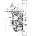
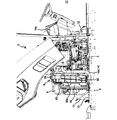
- FIG. 2 is a left side view showing the inside of the bonnet in the working vehicle shown in FIG.
- FIG. 3 is a plan view showing the inside of the bonnet.
- FIG. 4 is a left side view of the working vehicle in a state where the bonnet is located at the open position.
- FIG. 5 is a cross-sectional view of the bonnet taken longitudinally in front of the shroud in the working vehicle.
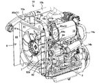
- FIG. 6 is a perspective view of an assembly including a cooling fan, a shroud, an intake pipe, and an engine in the working vehicle.
- FIG. 7 is a front view showing a state in which the intake pipe is removed from the assembly shown in FIG.
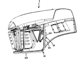
- FIG. 8 is a perspective view of the bonnet, with the side plate on one side of the bonnet 5 removed.
- FIG. 9 is a cross-sectional perspective view of the bonnet.
- FIG. 10 is a cross-sectional perspective view of the bonnet with the first elastic seal member removed from FIG. 9.
- FIG. 11 is an enlarged cross-sectional view of the shroud side flange and the vicinity of the bonnet side flange in a state where the bonnet is located at the closed position.
- FIG. 12 is a side view of the assembly shown in FIG.
- FIG. 13 is a partial cross-sectional plan view of the shroud.
- 14 is a cross-sectional plan view of the XIV portion in FIG.
- FIG. 15 is a partially longitudinal side view of the vicinity of the contact portion between the bonnet and the support plate.
- 16 is a vertical side view of the XVI portion in FIG.
- FIG. 17 is a schematic view of the first elastic seal member.
- FIG. 1 shows a left side view of a working vehicle 1 to which a bonnet structure according to an embodiment of the present invention is applied.
- the working vehicle 1 is a tractor to which a working machine can be attached.
- the working vehicle 1 surrounds a body frame 2, an engine 3 supported by the body frame 2, a pair of left and right traveling devices 4 driven by the engine 3, and the engine 3. And a bonnet 5 to be used.
- FIGS. 2 and 3 are a left side view and a plan view showing the inside of the bonnet 5 in the working vehicle 1.
- FIG. 4 shows a left side view of the working vehicle 1 in a state where the bonnet 5 is located at the open position.
- a radiator 6 and a cooling fan 7 are disposed in front of the engine 3 in order from the front to the rear of the vehicle, as shown in FIGS. 2 to 4.
- the cooling fan 7 is driven around the rotation shaft 71 along the vehicle longitudinal direction.
- the working vehicle 1 has a shroud 8 that surrounds the cooling fan 7. Further, the working vehicle 1 includes an air cleaner 9 disposed on the front side of the shroud 8, and an intake pipe 10 having one end connected to the air cleaner 9 and the other end connected to an intake port of the engine 3. And an exhaust silencer 15 having one end connected to the exhaust port of the engine 3.
- a driver seat installation space 11 in which a driver seat (not shown) is arranged is provided behind the engine 3 as shown in FIGS.
- the driver seat installation space 11 and the engine 3 are separated by an air cut plate 12.
- a dashboard 12a to which an operation member and an instrument panel (not shown) are attached is provided on the driver seat installation space 11 side of the air cut plate 12.
- the bonnet 5 is disposed in front of the air cut plate 12.
- the bonnet 5 is supported so as to be rotatable around a rotation shaft 51 (see FIGS. 1 and 4) along the vehicle width direction on the rear end side and the upper end side. That is, the bonnet 5 is closed around the rotating shaft 51 (see FIG. 2) and surrounds the radiator 6, the air cleaner 9, the shroud 8, the cooling fan 7, and the engine 3 (see FIG. 1). And an open position (see FIG. 4) for opening them.
- FIG. 5 shows a cross-sectional view of the bonnet 5 cut longitudinally in front of the shroud 8.
- the intake pipe 10 and the exhaust silencer 15 are arranged on one side and the other side in the vehicle width direction above the engine 3.
- the intake pipe 10 passes above the shroud 8 so as to extend in the vehicle front-rear direction across the shroud 8. That is, the shroud extends in the vehicle front-rear direction above the shroud 8 such that one end side and the other end side are positioned on the vehicle front-rear direction one side X1 and the other side X2 from the shroud 8, respectively.
- the upper surface of the bonnet 5 has the center in the vehicle width direction most in the vehicle width direction one side region 5R and the vehicle width direction other side region 5L facing the intake pipe 10 and the exhaust silencer 15, respectively.
- the vehicle curved direction central region 5C is recessed downward from the reference curved shape BC.
- the bonnet structure having the above-described configuration, the intake pipe 10 and the exhaust silencer 15 are distributed and arranged on one side and the other side in the vehicle width direction above the engine 3, and the intake pipe 10 is located above the shroud 8. Therefore, the bonnet 5 can be downsized in the vehicle width direction as compared with the conventional configuration in which the intake pipe passes through the side of the shroud. Furthermore, the upper surface of the bonnet 5 is positioned so that the center in the vehicle width direction is located at the uppermost position in the vehicle width direction one side region 5R and the vehicle width direction other side region 5L facing the intake pipe 10 and the exhaust silencer 15, respectively.
- the intake pipe 10 and the exhaust silencer 15 are located above the engine 3.
- the height of the central region 5C in the vehicle width direction of the bonnet 5 can be suppressed as low as possible. Therefore, it is possible to improve the driver's forward visibility while reducing the size of the engine unit including the intake pipe 10 and the exhaust silencer 15 and the bonnet 5 covering the engine unit in the vehicle width direction.
- the vehicle width direction central region 5C of the bonnet 5 has substantially the same curvature as the reference curved shape BC and is displaced downward as shown in FIG. According to such a configuration, it is possible to improve the aesthetics of the hood 5 while improving the forward visibility of the driver.
- the intake pipe 10 is disposed on one side in the vehicle width direction (right side in the traveling direction), and the exhaust silencer 15 is disposed on the other side in the vehicle width direction (left side in the traveling direction).
- the exhaust silencer 15 may be disposed on one side in the vehicle width direction, and the intake pipe 10 may be disposed on the other side in the vehicle width direction.
- the recess 850 of the shroud 8 is formed on the other side in the vehicle width direction.
- the intake pipe 10 extends in the vehicle front-rear direction with the shroud 8 interposed between the intake pipe 10 and a recess formed in the upper surface of the shroud 8. . That is, the upper surface of the shroud 8 is configured to form a recess 850 in which a region located on one side in the vehicle width direction is recessed downward as compared with the other portions.
- the intake pipe 10 extends in the vehicle front-rear direction with the shroud 8 sandwiched between the intake pipe 10 and the recess 850.
- the intake pipe 10 is disposed above the shroud 8 to reduce the size of the bonnet 5 in the vehicle width direction, and the bonnet 5 is positioned in the open position to thereby reduce the engine 3. Can be easily connected and disconnected between the intake pipe 10 and the air cleaner 9 while being mounted on the vehicle.
- the bonnet 5 is provided with a second elastic seal member 54 at a portion of the inner peripheral surface facing the upper surface of the shroud 8.
- the second elastic seal member 54 fills as much as possible a gap between the upper surface of the shroud 8 and the inner peripheral surface of the bonnet 5, so that the space between one side and the other side of the shroud 8 in the vehicle front-rear direction. It improves the sealing performance.
- FIG. 6 shows a perspective view of an assembly including the cooling fan 7, the shroud 8, the intake pipe 10, the engine 3, and the like.
- FIG. 7 is a front view showing the state where the intake pipe 10 is removed from the assembly.
- the intake pipe 10 passes above the shroud 8 in the vehicle front-rear direction while being positioned in the recess 850. Therefore, the second elastic seal member 54 directly abuts on the upper surface of the upper surface of the shroud 8 other than the concave portion 850, and the concave portion 850 passes the intake pipe 10 through the intake pipe 10. Abuts the top surface.
- the recess 850 includes a vertical surface 851 extending downward from one side in the vehicle width direction of the vehicle width direction central region 5C of the bonnet 5 and a lower end portion of the vertical surface 851 in the vehicle width direction. And a horizontal plane 852 extending to one side.
- the upper surface of the portion of the intake pipe 10 positioned in the recess 850 is inclined so as to be positioned downward as it goes outward in the vehicle width direction.
- the intake pipe 10 is made vertical by the second elastic seal member 54.
- the pressure is applied toward the surface 851 and the horizontal surface 852. Accordingly, it is possible to stabilize the support of the intake pipe 10 in a state where the bonnet 5 is located at the closed position.
- the recess 850 is provided on the right side in the vehicle width direction with reference to the vehicle forward direction.
- the side surface of the intake pipe 10 that is positioned in the recess 850 that faces the vertical surface 851 and the lower surface that faces the horizontal surface 852 have the shape of the recess 850 in the shroud 8. It is formed in a corresponding shape.
- the material of the second elastic seal member 54 for example, a urethane material can be used. Or it is good also as attaching the same sealing member as the 1st elastic sealing member 53 mentioned later via the flange provided in the internal peripheral surface of the said bonnet 5.
- a turbocharger 19 is provided above the engine 3 between the intake pipe 10 and the exhaust silencer 15 in the body width direction, as shown in FIG.
- the turbocharger 19 accelerates intake air introduced through the intake pipe 10 by exhaust gas introduced from the exhaust opening of the engine 3 through the exhaust pipe 14 and then introduces the intake air into the intake opening of the engine 3. It is configured.
- the intake pipe 10 has one end connected to the air cleaner 9 located on one side X1 in the vehicle front-rear direction with respect to the shroud 8, and the other end.
- a shroud passage 10a that passes through the recess 850 and extends from the shroud 8 to the other side X2 in the vehicle front-rear direction, one end is connected to the other end of the shroud passage 10a, and the other end is the intake air of the turbocharger 19
- the intake air inlet 10b is connected to the inlet
- the intake accelerator 10c has one end connected to the intake outlet of the turbocharger 19 and the other end connected to the intake of the engine 3.
- the exhaust pipe 14 has an exhaust introduction portion 14a that introduces exhaust from the exhaust port of the engine 3 into the exhaust inlet of the turbocharger 19, one end connected to the exhaust outlet of the turbocharger 19, and the other end.
- the exhaust conduction part 14b connected to the exhaust silencer 15, one end part connected to the exhaust silencer 15, and the other end part outside the bonnet 3 (more specifically, below and outward of the support plate 13 below) And an exhaust discharge portion 14c located at the same position.
- the shroud 8 includes a shroud main body 81 provided with an opening 81a surrounding the cooling fan 7, and extends outwardly in the vehicle width direction from both side surfaces of the shroud main body 81.
- the upper flange 85 has an upper contact surface 85 a facing upward, and the upper contact surface 85 a forms the upper surface of the shroud 8.
- the upper contact surface 85a has a central region 85a (1) corresponding to the shroud body 81 and a pair of side regions 85a (2) located on both sides of the central region 85a (1). .
- the pair of side regions 85 a (2) are configured to be lower and away from the side surface of the shroud main body 81 as going outward in the vehicle width direction.
- the shroud side flange 82 is front and rear facing the vehicle front-rear direction one side X1 (first direction) opposite to the pivot shaft 51 (see FIG. 2) with respect to the vehicle front-rear direction. It has a direction contact surface 82a.
- the front-rear direction abutting surface 82a abuts on a first elastic seal member 53 provided on the inner peripheral surface of the bonnet 5 when the bonnet 5 is positioned at the closed position.
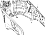
- FIG. 8 is a perspective view of the bonnet 5 and shows a perspective view in a state in which a side plate on one side of the bonnet 5 is removed.
- FIG. 9 shows a cross-sectional perspective view of the bonnet 5.
- FIG. 10 is a perspective view showing a state where the first elastic seal member 53 is removed from FIG.
- the bonnet 5 is provided with a bonnet side flange 52 extending inward from the inner peripheral surface, and the first elastic seal member 53 is attached to the bonnet side flange 52. ing.
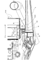
- FIG. 11 shows an enlarged cross-sectional view of the vicinity of the shroud side flange 82 and the bonnet side flange 52 when the bonnet 5 is positioned at the closed position.
- the bonnet side flange 52 is positioned on the vehicle front-rear direction one side X1 (first direction) side with respect to the shroud side flange 82 when the bonnet 5 is positioned at the closed position.
- the first elastic seal member 53 mounted on the bonnet side flange 52 is rotated around the rotation shaft 51 from the open position to the closed position.
- the front-rear direction contact surface 82a comes into contact with the first direction side.
- the first elastic seal member 53 when the bonnet 5 is rotated from the open position to the closed position, the first elastic seal member 53 is moved from the vehicle front-rear direction one side X1 (first direction) side. It is in close contact with the shroud side flange 82 in an elastically deformed state. According to such a configuration, the first elastic seal member 53 performs sealing between the shroud 8 and the side portion of the bonnet 5 while performing the opening and closing operation of the bonnet 5. It is possible to effectively prevent 53 from rubbing. Accordingly, it is possible to effectively prevent the first elastic seal member 53 from being worn, and to effectively prevent the disadvantage that the first elastic seal member 53 is detached from the bonnet 5 when the bonnet 5 is opened and closed. be able to.
- the first elastic sealing member 53 is a so-called weather strip having a string shape made of an elastic resin material such as rubber or sponge. Details will be described later.
- the rotating shaft 51 is disposed on the rear side of the engine 3 as shown in FIG. Accordingly, in the present embodiment, the front direction of the vehicle is the first direction.
- the first elastic sealing member 53 is configured to also seal between the bonnet 5 and the support plate 13 that supports the radiator 6. That is, as shown in FIGS. 3 and 4, the working vehicle 1 is the support plate 13 along the substantially horizontal direction so that the radiator 6 is placed, and the bonnet 5 is in the closed position. The support plate 13 is substantially covered by the bonnet 5 when it is formed. In the present embodiment, the shroud 8 is also supported by the support plate 13.
- the bonnet side flange 52 includes a pair of shroud corresponding regions 521 corresponding to the pair of shroud side flanges 82 and the support plate 13 when the bonnet 5 is positioned at the closed position. And a support plate corresponding region 522 facing each other.
- the first elastic seal member 53 is attached to the pair of shroud-corresponding regions 521, and is disposed on the front-rear direction contact surface 82a when the bonnet 5 is positioned at the closed position.
- a pair of shroud contact areas 531 that are in contact with each other and the support plate corresponding area 522 are attached to the upper surface of the support plate 13 from above when the bonnet 5 is rotated from the open position to the closed position.
- a support plate abutting region 532.
- the gap between the bonnet 5 and the support plate 13 can be sealed using the first elastic seal member 53 that seals between the bonnet 5 and the side of the shroud 8. it can. Accordingly, it is possible to effectively prevent an unnecessary object such as a bag from being sucked in between the bonnet 5 and the support plate 13. Furthermore, it is possible to prevent the exhaust discharged outside from the exhaust port of the engine 3 through the exhaust pipe 14 from entering between the bonnet 5 and the support plate 13, and thereby the radiator 6 and A decrease in cooling efficiency due to the cooling fan 7 can be more effectively prevented.
- FIG. 12 shows a side view of the assembly shown in FIG.
- the shroud side flange 82 is preferably inclined so as to be located on the side in the first direction (the front side in the present embodiment) as it goes downward.
- the bonnet side flange 52 is inclined corresponding to the shroud side flange 82. According to such a configuration, when the bonnet 5 is located at the closed position, the first elastic seal member 53 and the shroud side flange 82 can be brought into contact with each other more reliably, and the first elastic seal The sealing performance by the member 53 can be improved.
- the bonnet side flange 52 includes the shroud corresponding region 521 and the support plate corresponding region 522. Therefore, the shroud corresponding region 521 is inclined corresponding to the shroud side flange 82.
- the shroud-side flange 82 is configured such that the inclination angle in the lower end region 822 is larger than the inclination angle in the other main body region 821. That is, the lower end region 822 may be configured to be closer to the horizontal than the main body region 821. According to such a configuration, it is possible to prevent a large load from being applied to a boundary portion between the shroud contact region 531 and the support plate contact region 532 in the first elastic seal member 53.
- the shroud 8 extends from both side surfaces of the shroud main body 81 in the first direction (in the present embodiment, in front of the vehicle).
- FIG. 13 shows a partial cross-sectional plan view of the shroud 8.
- the first direction side reinforcing rib 83a is arranged so that the end of the first direction side approaches the side surface of the shroud body 81 as it goes in the first direction (that is, inward in the vehicle width direction).
- the taper shape is located at According to such a configuration, the first direction side reinforcing rib 83a that reinforces the shroud side flange 82 is guided by the first elastic seal member 53 when the bonnet 5 is turned from the open position to the closed position.
- the shroud 8 extends from both sides of the shroud main body 81 to the other side X ⁇ b> 2 in the vehicle front-rear direction opposite to the first direction (
- a second pair of left and right second reinforcing flanges 84 extending in the second direction as appropriate and extending rearward in the present embodiment, and the corresponding shroud-side flange 82 and second reinforcing flange 84 are connected.
- a direction-side reinforcing rib 84a is also connected to the shroud main body 81 to the other side X ⁇ b> 2 in the vehicle front-rear direction opposite to the first direction (
- a second pair of left and right second reinforcing flanges 84 extending in the second direction as appropriate and extending rearward in the present embodiment, and the corresponding shroud-side flange 82 and second reinforcing flange 84 are connected.
- a direction-side reinforcing rib 84a is
- the shroud side flange 82 is sandwiched by the first direction side reinforcing rib 83a and the second direction side reinforcing rib 84b from both sides in the longitudinal direction of the machine body. Strength can be improved effectively.
- the end of the first direction side reinforcing rib 83a on the side connected to the shroud side flange 82 is closer to the vehicle width direction than the outer end portion of the shroud side flange 82 in the vehicle width direction. It is located on the inner side (that is, the height of the first direction side reinforcing rib 83a is made smaller than the width of the shroud side flange 82), and the shroud side flange 81 is located on the first direction side.
- the front-rear direction contact surface 82a is sufficiently secured.
- the end of the second direction side reinforcing rib 84a that is connected to the shroud side flange 82 is closer to the fuselage than the end of the first direction side reinforcing rib 83a that is connected to the shroud side flange 82. It is located on the outer side in the width direction (that is, the second direction side reinforcing rib 84a is set higher than the first direction side reinforcing rib 83a), thereby ensuring the strength of the shroud side flange 82. is doing.
- the upper contact surface 85a and the front-rear direction contact surface 82a are overlapped in the vertical direction as shown in FIG. According to such a configuration, the gap between the shroud 8 and the bonnet 5 can be reliably sealed.
- the first elastic seal member 53 is configured to contact the shroud-side flange 82 in a state of being elastically deformed in the vehicle front-rear direction when the bonnet 5 is positioned at the closed position. ing. Specifically, as shown in FIG. 11, the bonnet side flange 52 and the shroud side flange 82 are overlapped in a front view along the vehicle front-rear direction when the bonnet 5 is located at the closed position. It is configured. On the other hand, as shown in FIG. 11, the first elastic seal member 53 has a U-shaped mounting portion 533 that elastically sandwiches the bonnet side flange 53, and the bonnet 5 is positioned at the closed position.
- a contact portion 534 extending from the mounting portion 533 toward the shroud-side flange 82 so that the contact portion 534 is elastically deformed in the vehicle front-rear direction. It is possible. According to the said structure, when the said bonnet 5 is located in a closed position, the said 1st elastic seal member 53 and the said shroud side flange 82 can be contact
- FIG. 14 is a cross-sectional plan view of the XIV portion in FIG.
- the shroud-corresponding region 521 of the bonnet side flange 52 is a first flange integrally formed with the bonnet 5 so as to extend inward from the inner peripheral surface of the bonnet 5.
- 523 and a second flange 524 fixed to the inner peripheral surface of the bonnet 5 so as to overlap the first flange 523.
- the second flange 524 is fixed to the inner peripheral surface of the bonnet 5 with a fastening member 525 such as a bolt.
- the first elastic seal member 53 is attached in a state where the mounting portion 533 sandwiches both the first flange 523 and the second flange 524.
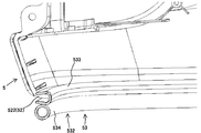
- FIG. 15 is a partial longitudinal side view of the vicinity of the contact portion between the bonnet 5 and the support plate 13.
- FIG. 16 shows a vertical side view of the XVI portion in FIG.
- the support plate corresponding region 522 of the bonnet side flange 52 is formed integrally with the bonnet 5. That is, a portion of the lower end portion of the bonnet 5 that faces the support plate 13 ends in a state of extending inward of the bonnet to form the support plate corresponding region 522.
- the first elastic seal member 53 is mounted on the support plate corresponding region 522 via the mounting portion 533 so that the contact portion 534 extends in the direction toward the support plate 13.
- the configuration of the bonnet side flange 52 is not limited to this as long as the first elastic seal member 53 can be reliably held. That is, for example, the shroud corresponding region 521 may be configured to have only one of the first flange 523 and the second flange 524. Alternatively, the members forming the shroud corresponding region 521 and the support plate corresponding region 522 may be fixed to the bonnet 5 by fastening members such as bolts and / or welding.
- the shroud 8 includes the shroud side flange 82 integrally formed with the shroud body 82.
- the shroud body 82 and the shroud side flange 82 are connected to each other. It can also be a separate body.
- FIG. 17 is a sectional view of a first elastic seal member applicable to the bonnet structure according to the present invention.
- FIG. 17A shows the first elastic seal member 53 applied to the present embodiment.
- the contact portion 534 of the first elastic seal member 53 has a hollow shape with a circular cross section or an elliptical shape, as shown in FIG.
- the mounting portion 533 includes a main body portion 533a having a U-shaped cross section and a plurality of first detachments extending inwardly from the inner peripheral surface of the main body portion 533a.
- a separation preventing portion 533b is a separation preventing portion 533b.
- the main body portion 533a has a pair of side walls facing both surfaces of the bonnet side flange 52, and an end wall that closes one end side of the pair of side walls, and the other end side of the pair of side walls is opened. Yes.
- the first detachment preventing portions 533b are disposed on both sides of the bonnet side flange 52 so as to come into contact with both surfaces of the bonnet side flange 52 when mounted on the bonnet side flange 52. . Further, the first detachment preventing portion 533b is inclined so as to go in the insertion direction of the bonnet side flange 52 from the base end portion toward the tip end portion. With the above configuration, the mounting portion 533 can be easily mounted on the bonnet side flange 52, and the first elastic seal member 53 is effectively prevented from being detached from the bonnet side flange 52. can do.
- the mounting portion 533 further includes a second detachment preventing portion 533c extending outward from the opening end of the main body portion 533a.
- the second detachment preventing portion 533c has an extending portion extending along one of the pair of side walls of the main body portion, and an inclined portion extending from the distal end portion of the extending portion toward the other of the pair of side walls. is doing. Similar to the first detachment preventing portion 533b, the inclined portion is inclined so as to go in the insertion direction of the bonnet side flange 52 from the proximal end portion toward the distal end portion. By having the said structure, it can prevent more effectively that the said mounting part 533 remove
- a metal core 537 having a U-shaped cross section is provided inside the main body portion 533a.
- the first elastic seal member 53 may be integrally formed of an elastic resin material such as rubber or urethane.
- the first elastic seal member 53b according to the first modification shown in FIG. 17B has a contact portion 534b having a claw-like cross section. That is, the contact portion 534b is partially cut away from the peripheral wall of the hollow contact portion 534 in the first elastic seal member 53 shown in FIG. As shown in FIG. 17B, the abutting portion 534b has a rectangular cross section, but it is of course possible to have a circular cross section or an elliptical cross section.
- the 1st elastic seal member 53c which concerns on the 2nd modification shown in FIG.17 (c) has the solid contact part 534c.
- the solid contact portion 534c is preferably formed of a material having a high expansion ratio (for example, a urethane foam material).
- the contact portion 534c has a substantially rectangular cross section with a flat contact surface with the shroud-side flange 82 or the support plate 13, but of course has a circular cross section or an elliptical cross section. Is also possible.
- the mounting portion 533 is omitted, and instead, the contact portion 534d is directly bonded to the bonnet side flange 52.
- the adhesive layer 533d is provided.
- the contact portion 534d has a hollow shape with a D-shaped cross section, but it is also possible to adopt a shape as shown in FIGS. 17 (a) to 17 (c).
- a filter 16 that removes impurities such as dust contained in the air introduced into the shroud 8 is provided in front of the shroud 8. Yes. Further, a battery 17 is placed in front of the filter 16. The battery 17 is also supported by the support plate 13.
- the air cleaner 9 is supported on the upper portion of the shroud 8 via a support member 18 as shown in FIGS.
- the shroud 8 and the support plate 13 may be integrally formed.
Landscapes
- Engineering & Computer Science (AREA)
- Chemical & Material Sciences (AREA)
- Combustion & Propulsion (AREA)
- Transportation (AREA)
- Mechanical Engineering (AREA)
- Superstructure Of Vehicle (AREA)
- Cooling, Air Intake And Gas Exhaust, And Fuel Tank Arrangements In Propulsion Units (AREA)
Abstract
Description
従って、前記シュラウド側弾性シール部材の上方部分と前記ボンネット側弾性シール部材の対応部分とは、前記ボンネットの開閉動作の際に擦れ合うことはない。
つまり、前記シュラウド側弾性シール部材の側方部分と前記ボンネット側弾性シール部材の対応部分とは、前記ボンネットの開閉動作の際に互いに擦れ合うことになり、その結果、前記シュラウド側弾性シール部材及び/又はボンネット側弾性シール部材の過磨耗や、場合によっては前記シュラウド側弾性シール部材及び/又はボンネット側弾性シール部材の前記シュラウド及び/又は前記ボンネットからの脱離という不具合が生じる。
即ち、前記従来のボンネット構造においては、前記吸気管が前記シュラウドの側方を通って車輌前後方向に延びており、従って、前記吸気管及び前記排気サイレンサを含むエンジンユニット及び前記エンジンユニットを覆う前記ボンネットが車輌幅方向に関し大型化するという問題があった。
即ち、本願は、車輌前方から後方へ順に配設されたラジエター、冷却ファン及びエンジンと、前記冷却ファンを囲繞するシュラウドと、前記シュラウドより前方側に配設されたエアクリーナと、一端部が前記エアクリーナに接続され且つ他端部が前記エンジンの吸気口に接続される吸気管と、一端部が前記エンジンの排気口に接続される排気サイレンサと、これらの部材を閉塞する閉位置及び開放する開位置をとり得るように車輌幅方向に沿った回動軸回り回動可能とされたボンネットとを備えた作業車輌に適用されるボンネット構造であって、前記吸気管及び前記排気サイレンサを含むエンジンユニット及び前記エンジンユニットを覆う前記ボンネットを車輌幅方向に関し小型化させつつ、運転者の前方視界性を向上させ得るボンネット構造を含んでいる。
さらに、前記ボンネットの上面は、前記吸気管及び前記排気サイレンサとそれぞれ対向する車輌幅方向一方側領域及び車輌幅方向他方側領域においては車輌幅方向中央が最も上方に位置するような基準湾曲形状に沿っており、且つ、車輌幅方向中央領域においては前記基準湾曲形状より下方へ凹まされているため、前記エンジンの上方において前記吸気管及び前記排気サイレンサが配置された構成においても、前記ボンネットの上面の高さを可及的に低く抑えることができる。
従って、前記吸気管及び前記排気サイレンサを含むエンジンユニット及び前記エンジンユニットを覆う前記ボンネットを車輌幅方向に関し小型化させつつ、運転者の前方視界性を向上させることができる。
図1に、本発明の一実施の形態に係るボンネット構造が適用された作業車輌1の左側面図を示す。
図1に示すように、前記作業車輌1は、作業機が付設可能とされたトラクタとされている。
前記作業車輌1は、図1に示すように、機体フレーム2と、前記機体フレーム2に支持されるエンジン3と、前記エンジン3によって駆動される左右一対の走行装置4と、前記エンジン3を囲繞するボンネット5とを有している。
前記ボンネット5内において、前記エンジン3の前方には、図2から図4に示すように、車輌前方から後方へ順にラジエター6及び冷却ファン7が配設されている。
本実施の形態において、前記冷却ファン7は、車輌前後方向に沿った回転軸71回りに駆動される。
さらに、前記作業車輌1は、前記シュラウド8より前方側に配設されたエアクリーナ9と、一端部が前記エアクリーナ9に接続され且つ他端部が前記エンジン3の吸気口に接続される吸気管10と、一端部が前記エンジン3の排気口に接続される排気サイレンサ15とを有している。
前記ボンネット5は、前記エアカットプレート12より前方に配置されている。
前記ボンネット5は、後端側且つ上端側において車輌幅方向に沿った回動軸51(図1及び図4参照)回り回動可能に支持されている。
即ち、前記ボンネット5は、前記回動軸51(図2参照)回りに、前記ラジエター6、前記エアクリーナ9、前記シュラウド8、前記冷却ファン7及び前記エンジン3を囲繞する閉位置(図1参照)と、これらを開放する開位置(図4参照)とをとり得る。
本実施の形態においては、前記吸気管10及び前記排気サイレンサ15は、図3及び図5に示すように、前記エンジン3の上方において車輌幅方向一方側及び他方側に振り分け配置されている。
詳しくは、前記吸気管10は、図3及び図5に示すように、前記シュラウド8を挟んで車輌前後方向に延びるように、前記シュラウド8の上方を通過している。即ち、前記シュラウドは、一端側及び他端側がそれぞれ前記シュラウド8より車輌前後方向一方側X1及び他方側X2に位置するように、前記シュラウド8の上方において車輌前後方向に延びている。
さらに、前記ボンネット5の上面は、前記吸気管10及び前記排気サイレンサ15とそれぞれ対向する車輌幅方向一方側領域5R及び車輌幅方向他方側領域5Lにおいては車輌幅方向中央が最も上方に位置するような基準湾曲形状BCに沿っており、且つ、車輌幅方向中央領域5Cにおいては前記基準湾曲形状BCより下方へ凹まされているため、前記エンジン3の上方に前記吸気管10及び前記排気サイレンサ15が配置されているにも拘わらず、前記ボンネット5の車輌幅方向中央領域5Cの高さを可及的に低く抑えることができる。
従って、前記吸気管10及び前記排気サイレンサ15を含むエンジンユニット並びに前記エンジンユニットを覆う前記ボンネット5を車輌幅方向に関し小型化させつつ、運転者の前方視界性を向上させることができる。
斯かる構成によれば、運転者の前方視界性を向上させつつ、前記ボンネット5の美観性を向上させることができる。
また、本実施の形態においては、前記吸気管10が車輌幅方向一方側(進行方向右側)に配置され、且つ、前記排気サイレンサ15が車輌幅方向他方側(進行方向左側)に配置されている。ただし、前記排気サイレンサ15が車輌幅方向一方側に配置され、且つ、前記吸気管10が車輌幅方向他方側に配置されることとしてもよい。この際、前記シュラウド8の凹部850は、車輌幅方向他方側に形成される。
即ち、前記シュラウド8の上面は、車輌幅方向一方側に位置する領域が他の部分に比して下方へ凹まされた凹部850を形成するように構成されている。
そして、前記吸気管10は、前記凹部850内に位置された状態で前記シュラウド8を挟んで車輌前後方向に延びている。
斯かる構成によれば、前記シュラウド8の上方に前記吸気管10を配設することで前記ボンネット5を車輌幅方向に関し小型化させつつ、前記ボンネット5を開位置に位置させることで前記エンジン3を車輌本機に搭載させたままの状態で前記吸気管10と前記エアクリーナ9との接続作業及び接続解除作業を容易に行うことができる。
図6に、前記冷却ファン7,前記シュラウド8,前記吸気管10及び前記エンジン3等を含むアッセンブリの斜視図を示す。
又、図7に、前記アッセンブリから前記吸気管10を取り除いた状態の正面図を示す。
従って、前記第2弾性シール部材54は、前記シュラウド8の上面のうち前記凹部850以外の領域においては前記上面に直接的に当接し、且つ、前記凹部850においては前記吸気管10を介して前記上面に当接する。
一方、図5に示すように、前記吸気管10のうち前記凹部850に位置される部分の上面は、車輌幅方向外方へ行くに従って下方に位置するように傾斜されている。
前記吸気管10のうち前記凹部850に位置される部分の前記垂直面851に対向する側面及び前記水平面852に対向する下面は、図5に示すように、前記シュラウド8における前記凹部850の形状に対応した形状に形成されている。
上記構成とすることにより、前記ボンネット5を閉位置に位置させた際に、前記ボンネット5に押圧された前記吸気管10が前記シュラウド8の前記凹部850に密接する。従って、前記凹部850におけるシール性を向上させ且つ前記吸気管10の振動を有効に防止することができる。
図5~図7に示すように、前記シュラウド8は、前記冷却ファン7を囲繞する開口81aが設けられたシュラウド本体81と、前記シュラウド本体81の両側面から車輌幅方向外方へ延在する左右一対のシュラウド側フランジ82と、前記一対のシュラウド側フランジ82の一方の上端部から前記シュラウド本体81の上端部を跨いで前記一対のシュラウド側フランジ82の他方の上端部へ至る上方フランジ85とを有している。
前記上方当接面85aは、前記シュラウド本体81に対応した中央領域85a(1)と、前記中央領域85a(1)の両側に位置する一対の側方領域85a(2)とを有している。
前記一対の側方領域85a(2)は、車輌幅方向外方へ行くに従って下方且つ前記シュラウド本体81の側面から離間するように構成されている。
前記前後方向当接面82aは、前記ボンネット5が閉位置に位置された際に、前記ボンネット5の内周面に設けられた第1弾性シール部材53と当接する。
図9に、前記ボンネット5の横断斜視図を示す。さらに、図10に、図9から前記第1弾性シール部材53を取り外した状態の斜視図を示す。
図11に示すように、前記ボンネット側フランジ52は、前記ボンネット5が閉位置に位置された際に前記シュラウド側フランジ82より車輌前後方向一方側X1(第1方向)の側に位置するように前記ボンネット5に設けられており、従って、前記ボンネット側フランジ52に装着された前記第1弾性シール部材53は、前記ボンネット5が前記回動軸51回りに開位置から閉位置へ回動される際に、前記前後方向当接面82aに前記第1方向の側から当接するようになっている。
斯かる構成によれば、前記第1弾性シール部材53によって前記シュラウド8と前記ボンネット5の側方部分との間のシールを行いつつ、前記ボンネット5の開閉動作の際に前記第1弾性シール部材53が擦れることを有効に防止することができる。従って、前記第1弾性シール部材53の磨耗を有効に防止することができるとともに、前記ボンネット5の開閉動作時に前記第1弾性シール部材53が前記ボンネット5から脱離するという不都合を有効に防止することができる。
本実施の形態において、前記第1弾性シール部材53は、ゴムやスポンジ等の弾性樹脂材料からなるひも状のいわゆるウェザーストリップである。詳細は後述する。
なお、本実施の形態においては、前記回動軸51は、図2に示すように、前記エンジン3より後方側に配置されている。従って、本実施の形態においては、車輌前方が前記第1方向となる。
即ち、図3及び図4に示すように、前記作業車輌1は、前記ラジエター6が載置されるように略水平方向に沿った前記支持プレート13であって、前記ボンネット5が閉位置に位置された際に前記ボンネット5によって略覆われる前記支持プレート13を有している。
なお、本実施の形態においては、前記シュラウド8も前記支持プレート13に支持されている。
さらに、前記エンジン3の排気口から前記排気管14を介して外部に放出される排気が前記ボンネット5及び前記支持プレート13の間から入り込むことを防止することができ、これにより、前記ラジエター6及び前記冷却ファン7による冷却効率の低下をより有効に防止することができる。
図4,図6及び図12に示すように、前記シュラウド側フランジ82は、好ましくは、下方へ行くに従って前記第1方向の側(本実施の形態においては前方側)に位置するように傾斜され、前記ボンネット側フランジ52は、前記シュラウド側フランジ82に対応して傾斜されている。
斯かる構成によれば、前記ボンネット5が閉位置に位置された際に、前記第1弾性シール部材53と前記シュラウド側フランジ82とをより確実に当接させることができ、前記第1弾性シール部材53によるシール性を向上させることができる。
本実施の形態においては、前述の通り、前記ボンネット側フランジ52は、前記シュラウド対応領域521及び前記支持プレート対応領域522を含んでいる。従って、前記シュラウド対応領域521が前記シュラウド側フランジ82に対応して傾斜されている。
斯かる構成によれば、前記第1弾性シール部材53における前記シュラウド当接領域531及び前記支持プレート当接領域532間の境界部分に大きな負荷が掛かることを防止できる。
図13に示すように、前記第1方向側補強リブ83aは、第1方向側の端部が第1方向へ行くに従って前記シュラウド本体81の側面に近接するような(即ち、車輌幅方向内方に位置するような)テーパ形状とされている。
斯かる構成によれば、前記シュラウド側フランジ82を補強する前記第1方向側補強リブ83aを、前記ボンネット5が開位置から閉位置に回動される際の前記第1弾性シール部材53のガイドとして作用させることができる。
一方、前記第2方向側補強リブ84aにおける前記シュラウド側フランジ82に連結される側の端部は、前記第1方向側補強リブ83aにおける前記シュラウド側フランジ82に連結される側の端部より機体幅方向外方側に位置しており(即ち、前記第2方向側補強リブ84aは前記第1方向側補強リブ83aより高く設定されており)、これにより、前記シュラウド側フランジ82の強度を確保している。
斯かる構成によれば、前記シュラウド8と前記ボンネット5との間の隙間を確実にシールすることができる。
詳しくは、図11に示すように、前記ボンネット側フランジ52及び前記シュラウド側フランジ82は、前記ボンネット5が閉位置に位置された際に、車輌前後方向に沿った正面視においてオーバーラップするように構成されている。
一方、前記第1弾性シール部材53は、図11に示すように、前記ボンネット側フランジ53を弾性的に挟持する断面コの字状の装着部533と、前記ボンネット5が閉位置に位置された際に前記前後方向当接面82aに当接されるように前記装着部533から前記シュラウド側フランジ82へ向かって延びる当接部534とを備え、前記当接部534が車輌前後方向に弾性変形可能とされている。
上記構成によれば、前記ボンネット5が閉位置に位置された際に、前記第1弾性シール部材53と前記シュラウド側フランジ82とをより確実に当接させることができ、前記第1弾性シール部材53によるシール性を向上させることができる。
図10及び図14に示すように、前記ボンネット側フランジ52の前記シュラウド対応領域521は、前記ボンネット5の内周面から内方へ延在するように前記ボンネット5に一体形成された第1フランジ523と、前記第1フランジ523と重合されるように前記ボンネット5の内周面に固着された第2フランジ524とを有している。
本実施の形態においては、前記第2フランジ524は前記ボンネット5の内周面にボルト等の締結部材525で固定されている。
前記第1弾性シール部材53は、前記装着部533が前記第1フランジ523及び前記第2フランジ524の双方を挟み込んだ状態で取り付けられている。
又、図16に、図9におけるXVI部の縦断側面図を示す。
図10,図15及び図16に示すように、前記ボンネット側フランジ52の前記支持プレート対応領域522は前記ボンネット5に一体的に形成されている。
即ち、前記ボンネット5の下端部のうち前記支持プレート13に対向する部分は、前記ボンネットの内方へ延在された状態で終焉して前記支持プレート対応領域522を形成している。
前記第1弾性シール部材53は、前記当接部534が前記支持プレート13に方向へ延びるように前記装着部533を介して前記支持プレート対応領域522に装着されている。
即ち、例えば、前記シュラウド対応領域521が前記第1フランジ523又は前記第2フランジ524の何れか一方だけを有するように構成することも可能である。
若しくは、前記シュラウド対応領域521及び前記支持プレート対応領域522を形成する部材を、ボルト等の締結部材及び/又は溶接によって前記ボンネット5に固定することも可能である。
本実施の形態において、前記第1弾性シール部材53の前記当接部534は、図17(a)に示すように、断面円形又は楕円形の中空形状を有している。
また、前記装着部533は、図17(a)に示すように、断面コの字状の本体部533aと、前記本体部533aの内周面から内方へ延在された複数の第1脱離防止部533bとを有している。
前記本体部533aは、前記ボンネット側フランジ52の両面と対向する一対の側壁と、前記一対の側壁の一端側を閉塞する端壁とを有し、前記一対の側壁の他端側が開口とされている。
前記第1脱離防止部533bは、前記ボンネット側フランジ52に装着された際に、前記ボンネット側フランジ52の両面にそれぞれ当接するように、前記ボンネット側フランジ52を挟んで両側に配置されている。さらに、前記第1脱離防止部533bは、基端部から先端部に向かうに従って前記ボンネット側フランジ52の挿通方向へ向かうように傾斜配置されている。
上記構成を有することにより、前記装着部533を前記ボンネット側フランジ52に容易に装着することができ、しかも、前記ボンネット側フランジ52から前記第1弾性シール部材53が脱離することを有効に防止することができる。
前記第2脱離防止部533cは、前記本体部の一対の側壁の一方に沿って延びる延在部と、前記延在部の先端部から一対の側壁の他方へ向かって延びる傾斜部とを有している。
前記傾斜部は、前記第1脱離部防止部533bと同様に、基端部から先端部に向かうに従って前記ボンネット側フランジ52の挿通方向へ向かうように傾斜配置されている。
上記構成を有することにより、前記ボンネット側フランジ52から前記装着部533が脱離することをより有効に防止することができる。
上記構成を有することにより、前記第1脱離部防止部533b,前記第2脱離防止部533c及び前記当接部534の弾性変形を許容しつつ、前記本体部533aの変形を防止することができる。
前記第1弾性シール部材53は、ゴムやウレタン等の弾性を有する樹脂材料で一体的に形成され得る。
なお、図17(b)に示すように、前記当接部534bは断面矩形状とされているが、当然ながら、断面円形状又は断面楕円形状とすることも可能である。
なお、前記当接部534cは、前記シュラウド側フランジ82又は前記支持プレート13との当接面が平坦な断面略矩形状とされているが、当然ながら、断面円形状又は断面楕円形状とすることも可能である。
なお、前記当接部534dは、断面D字状の中空形状とされているが、図17(a)から図17(c)に示すような形状を採用することも可能である。
さらに、前記フィルタ16の前方には、バッテリ17が載置されている。前記バッテリ17も前記支持プレート13に支持されている。
例えば、前記シュラウド8と前記支持プレート13は、一体的に形成されてもよい。
3 エンジン
5 ボンネット
5R 車輌幅方向一方側領域
5L 車輌幅方向他方側領域
5C 車輌幅方向中央領域
6 ラジエター
7 冷却ファン
8 シュラウド
9 エアクリーナ
10 吸気管
13 支持プレート
15 排気サイレンサ
51 回動軸
52 ボンネット側フランジ
521 シュラウド対応領域
522 支持プレート対応領域
53,53b,53c,53d 第1弾性シール部材
531 シュラウド当接領域
532 支持プレート当接領域
533 装着部
534,534b,534c,534d 当接部
54 第2弾性シール部材
81 シュラウド本体
81a 開口
82 シュラウド側フランジ
82a 前後方向当接面
83 補強フランジ
83a 第1方向側補強リブ
85 上方フランジ
85a 上方当接面
850 凹部
851 垂直面
852 水平面
X1 車輌前後方向一方側(第1方向)
BC 基準湾曲形状
Claims (10)
- 車輌前方から後方へ順に配設されたラジエター、冷却ファン及びエンジンと、前記冷却ファンを囲繞するシュラウドと、前記シュラウドより前方側に配設されたエアクリーナと、一端部が前記エアクリーナに接続され且つ他端部が前記エンジンの吸気口に接続される吸気管と、これらの部材を閉塞する閉位置及び開放する開位置をとり得るように車輌幅方向に沿った回動軸回り回動可能とされたボンネットとを備えた作業車輌に適用されるボンネット構造であって、
前記シュラウドは、前記冷却ファンを囲繞する開口が設けられたシュラウド本体と、前記シュラウド本体の両側から車輌幅方向外方へ延在する左右一対のシュラウド側フランジであって、車輌前後方向に関し前記回動軸とは反対側の第1方向を向く前後方向当接面を有する一対のシュラウド側フランジとを有し、
前記ボンネットには、内周面から内方へ延在するボンネット側フランジと、前記ボンネット側フランジに装着される第1弾性シール部材とが設けられ、
前記ボンネット側フランジは、前記ボンネットが閉位置に位置された際に前記一対のシュラウド側フランジより前記第1方向の側に位置するように前記ボンネットに設けられ、
前記ボンネットが前記回動軸回りに開位置から閉位置へ回動される際に、前記第1弾性シール部材は前記前後方向当接面に前記第1方向の側から当接されることを特徴とするボンネット構造。 - 前記一対のシュラウド側フランジは、下方へ行くに従って前記第1方向の側に位置するように傾斜されており、
前記ボンネット側フランジは、前記シュラウド側フランジに対応して傾斜されていることを特徴とする請求項1に記載のボンネット構造。 - 前記ボンネットが閉位置に位置された際に、前記ボンネット側フランジ及び前記シュラウド側フランジは車輌前後方向に沿った正面視においてオーバーラップするように構成され、
前記第1弾性シール部材は、前記ボンネット側フランジを弾性的に挟持する断面コの字状の装着部と、前記ボンネットが閉位置に位置された際に前記前後方向当接面に当接されるように前記装着部から前記シュラウド側フランジへ向かって延びる当接部とを備え、
前記当接部は、前記当接部が前記装着部から延びる方向に弾性変形可能とされていることを特徴とする請求項1又は2に記載のボンネット構造。 - 前記シュラウドは、前記シュラウド本体の両側から前記第1方向へ延在する左右一対の補強フランジと、対応する前記シュラウド側フランジ及び前記補強フランジの間を連結する第1方向側補強リブとを有し、
前記第1方向側補強リブの前記第1方向側の端部は、前記第1方向へ行くに従って車輌幅方向内方に位置するようなテーパ形状とされていることを特徴とする請求項1から3の何れかに記載のボンネット構造。 - 前記シュラウドは、前記一対のシュラウド側フランジの一方の上端部から前記シュラウド本体の上端部を跨いで前記一対のシュラウド側フランジの他方の上端部へ至る上方フランジであって、上方を向く上方当接面を有する上方フランジを有し、
前記ボンネットの内周面には第2弾性シール部材が設けられ、
前記ボンネットが前記回動軸回りに開位置から閉位置へ回動される際に、前記第2弾性シール部材は前記上方当接面に直接又は間接的に上方から当接されることを特徴とする請求項1から4の何れかに記載のボンネット構造。 - 前記上方当接面は、車輌幅方向一方側に上方に開く凹部であって、前記吸気管が前記シュラウドを挟んで車輌前後方向に延びることを許容する凹部を有し、
前記第2弾性シール部材は、前記ボンネットが前記回動軸回りに開位置から閉位置へ回動される際に、前記上方当接面のうち前記凹部が形成された部位においては前記吸気管に上方から当接されることを特徴とする請求項5に記載のボンネット構造。 - 前記前後方向当接面及び前記上方当接面は、上下方向に関しオーバーラップされていることを特徴とする請求項5又は6に記載のボンネット構造。
- 前記回動軸は、前記第1方向が車輌前方となるように前記エンジンより後方側に配置されており、
前記ラジエターは、略水平方向に沿った支持プレートに支持され、
前記ボンネット側フランジは、前記一対のシュラウド側フランジに対応した一対のシュラウド対応領域と、前記ボンネットが閉位置に位置された際に前記支持プレートと対向する支持プレート対応領域とを含み、
前記第1弾性シール部材は、前記一対のシュラウド対応領域に装着され、前記ボンネットが閉位置に位置された際に前記前後方向当接面に当接される一対のシュラウド当接領域と、前記支持プレート対応領域に装着され、前記ボンネットが開位置から閉位置へ回動される際に前記支持プレートの上面に上方から当接される支持プレート当接領域とを有していることを特徴とする請求項1から7の何れかに記載のボンネット構造。 - 車輌前方から後方へ順に配設されたラジエター、冷却ファン及びエンジンと、前記冷却ファンを囲繞するシュラウドと、前記シュラウドより前方側に配設されたエアクリーナと、一端部が前記エアクリーナに接続され且つ他端部が前記エンジンの吸気口に接続される吸気管と、一端部が前記エンジンの排気口に接続される排気サイレンサと、これらの部材を閉塞する閉位置及び開放する開位置をとり得るように車輌幅方向に沿った回動軸回り回動可能とされたボンネットとを備えた作業車輌に適用されるボンネット構造であって、
前記吸気管及び前記排気サイレンサは、前記エンジンの上方において車輌幅方向一方側及び他方側に振り分け配置され、
前記吸気管は、前記シュラウドの上方において前記シュラウドを挟んで車輌前後方向に延びており、
前記ボンネットの上面は、前記吸気管及び前記排気サイレンサとそれぞれ対向する車輌幅方向一方側領域及び車輌幅方向他方側領域においては車輌幅方向中央が最も上方に位置するような基準湾曲形状に沿っており、且つ、車輌幅方向中央領域においては前記基準湾曲形状より下方へ凹まされていることを特徴とするボンネット構造。 - 前記ボンネットには、内周面のうち前記シュラウドと対向する部分に弾性シール部材が設けられ、
前記シュラウドの上面は、車輌幅方向一方側に位置する領域に他の部分に比して下方へ凹まされた凹部であって、車輌幅方向中央領域の車輌幅方向一方側から下方へ延びる垂直面と前記垂直面の下端部から車輌幅方向一方側へ延びる水平面とによって画される凹部を有しており、
前記吸気管は、前記シュラウドの上面に形成された前記凹部を介して前記シュラウドを挟んで車輌前後方向に延びており、
前記吸気管のうち前記凹部に位置される部分の上面は、車輌幅方向外方へ行くに従って下方に位置するように傾斜されていることを特徴とする請求項9に記載のボンネット構造。
Priority Applications (4)
| Application Number | Priority Date | Filing Date | Title |
|---|---|---|---|
| CN200980154076.7A CN102271989B (zh) | 2009-01-09 | 2009-12-10 | 发动机罩结构 |
| KR1020167014480A KR101671256B1 (ko) | 2009-01-09 | 2009-12-10 | 보닛 구조 |
| US13/143,885 US8371408B2 (en) | 2009-01-09 | 2009-12-10 | Bonnet structure |
| EP09837553.8A EP2384954B1 (en) | 2009-01-09 | 2009-12-10 | Bonnet structure |
Applications Claiming Priority (2)
| Application Number | Priority Date | Filing Date | Title |
|---|---|---|---|
| JP2009003939A JP5184387B2 (ja) | 2009-01-09 | 2009-01-09 | ボンネット構造 |
| JP2009-003939 | 2009-01-09 |
Publications (1)
| Publication Number | Publication Date |
|---|---|
| WO2010079667A1 true WO2010079667A1 (ja) | 2010-07-15 |
Family
ID=42316437
Family Applications (1)
| Application Number | Title | Priority Date | Filing Date |
|---|---|---|---|
| PCT/JP2009/070664 Ceased WO2010079667A1 (ja) | 2009-01-09 | 2009-12-10 | ボンネット構造 |
Country Status (6)
| Country | Link |
|---|---|
| US (1) | US8371408B2 (ja) |
| EP (1) | EP2384954B1 (ja) |
| JP (1) | JP5184387B2 (ja) |
| KR (2) | KR101671256B1 (ja) |
| CN (1) | CN102271989B (ja) |
| WO (1) | WO2010079667A1 (ja) |
Cited By (2)
| Publication number | Priority date | Publication date | Assignee | Title |
|---|---|---|---|---|
| WO2014200021A1 (ja) * | 2013-06-14 | 2014-12-18 | ヤンマー株式会社 | 作業車両 |
| JP2017218150A (ja) * | 2017-09-20 | 2017-12-14 | 井関農機株式会社 | トラクタ |
Families Citing this family (24)
| Publication number | Priority date | Publication date | Assignee | Title |
|---|---|---|---|---|
| JP5483857B2 (ja) * | 2008-10-20 | 2014-05-07 | ヤンマー株式会社 | 走行車両搭載用のエンジン装置 |
| US8303029B2 (en) * | 2009-11-16 | 2012-11-06 | Kawasaki Jukogyo Kabushiki Kaisha | Utility vehicle |
| US8256551B2 (en) * | 2009-12-30 | 2012-09-04 | Agco Corporation | Agricultural vehicle cooling assembly fan shroud with seals for pass-through cooling and exhaust tubes |
| CN102383926B (zh) * | 2011-10-23 | 2013-02-06 | 浙江乐恒动力科技有限公司 | 一种发动机驱动的箱式发电机 |
| DE202012003756U1 (de) * | 2012-04-13 | 2012-04-25 | Joseph Vögele AG | Chassis für eine Straßenbaumaschine |
| JP6014410B2 (ja) * | 2012-08-08 | 2016-10-25 | ヤンマー株式会社 | 作業車両 |
| US9623912B2 (en) * | 2012-09-20 | 2017-04-18 | Polaris Industries Inc. | Utility vehicle |
| US9440671B2 (en) | 2012-09-20 | 2016-09-13 | Polaris Industries Inc. | Vehicle |
| JP5821872B2 (ja) * | 2013-02-22 | 2015-11-24 | コベルコ建機株式会社 | 建設機械の吸気構造 |
| US9073581B2 (en) * | 2013-03-07 | 2015-07-07 | Kubota Corporation | Working vehicle |
| CN104185723B (zh) * | 2013-03-26 | 2015-11-25 | 株式会社小松制作所 | 作业车辆及轮式装载机 |
| JP5382672B1 (ja) * | 2013-03-29 | 2014-01-08 | 株式会社小松製作所 | ブルドーザ |
| JP5673775B1 (ja) * | 2013-10-25 | 2015-02-18 | 井関農機株式会社 | 作業車両 |
| JP6193109B2 (ja) * | 2013-12-11 | 2017-09-06 | ヤンマー株式会社 | 作業車両 |
| EP3127734B1 (en) * | 2014-03-28 | 2021-11-03 | Yanmar Power Technology Co., Ltd. | Tractor |
| EP3127787B1 (en) * | 2014-03-28 | 2018-12-19 | Yanmar Co., Ltd. | Industrial vehicle |
| EP3009759B1 (en) * | 2014-03-31 | 2018-03-21 | Komatsu Ltd. | Utility vehicle |
| JP2015223993A (ja) * | 2014-05-29 | 2015-12-14 | ヤンマー株式会社 | 作業車両 |
| JP2016030559A (ja) | 2014-07-30 | 2016-03-07 | ヤンマー株式会社 | 作業車両 |
| CN106143640A (zh) * | 2015-04-28 | 2016-11-23 | 长城汽车股份有限公司 | 发动机罩内板结构及发动机罩 |
| CN105015628A (zh) * | 2015-07-23 | 2015-11-04 | 广西柳工机械股份有限公司 | 发动机罩密封装置 |
| US9764776B2 (en) * | 2015-12-18 | 2017-09-19 | Honda Motor Co., Ltd. | Motor vehicle engine room air and water management system |
| JP6328174B2 (ja) | 2016-06-09 | 2018-05-23 | 本田技研工業株式会社 | 排気装置 |
| JP7211922B2 (ja) | 2019-09-27 | 2023-01-24 | 株式会社クボタ | 作業車 |
Citations (5)
| Publication number | Priority date | Publication date | Assignee | Title |
|---|---|---|---|---|
| JPS56111017U (ja) * | 1980-01-29 | 1981-08-27 | ||
| JPS5725076U (ja) * | 1980-07-18 | 1982-02-09 | ||
| JP2756344B2 (ja) * | 1990-04-07 | 1998-05-25 | ヤンマーディーゼル株式会社 | トラクタのボンネット機構 |
| JPH1193664A (ja) * | 1997-09-24 | 1999-04-06 | Kubota Corp | ボンネット付きエンジン作業機 |
| US7418994B2 (en) * | 2004-06-11 | 2008-09-02 | Deere & Company | Fan shroud with integral hood seal |
Family Cites Families (14)
| Publication number | Priority date | Publication date | Assignee | Title |
|---|---|---|---|---|
| US4018270A (en) * | 1975-11-06 | 1977-04-19 | International Harvester Company | Automotive fan shroud for screening debris |
| US4126199A (en) * | 1977-05-09 | 1978-11-21 | Allis-Chalmers Corporation | Bottom serviced air cleaner for a motor vehicle |
| JPS56111017A (en) * | 1980-02-06 | 1981-09-02 | Takeshi Yamamoto | Moving type suction treatment apparatus |
| JPS5725076A (en) | 1980-07-23 | 1982-02-09 | Hitachi Ltd | Method for binary-coding of video signal |
| JPH02128918A (ja) * | 1988-11-09 | 1990-05-17 | Honda Motor Co Ltd | トラクターのボンネット内シール構造 |
| JP3469059B2 (ja) * | 1997-09-19 | 2003-11-25 | 株式会社クボタ | 走行車両のエンジンルーム構造 |
| EP0906863B1 (en) * | 1997-10-02 | 2005-03-16 | Kanzaki Kokyukoki Mfg. Co., Ltd. | Panel mounting system of a vehicle |
| US6318450B1 (en) * | 2000-08-22 | 2001-11-20 | Delphi Technologies, Inc. | Fastener free automotive heat exchanger mounting |
| US6460644B1 (en) * | 2000-08-24 | 2002-10-08 | Deere & Company | Two position tilt hood |
| US20040262061A1 (en) * | 2003-06-25 | 2004-12-30 | Case, Llc | Work vehicle hood |
| WO2005014373A1 (ja) * | 2003-08-12 | 2005-02-17 | Yanmar Co., Ltd. | トラクタ |
| US7575081B2 (en) * | 2004-03-29 | 2009-08-18 | Kubota Corporation | Work vehicle |
| JP4613082B2 (ja) * | 2005-03-14 | 2011-01-12 | ヤンマー株式会社 | 作業車両のボンネット構造 |
| JP2007083916A (ja) * | 2005-09-22 | 2007-04-05 | Toyota Auto Body Co Ltd | 自動車のフードシール構造 |
-
2009
- 2009-01-09 JP JP2009003939A patent/JP5184387B2/ja not_active Expired - Fee Related
- 2009-12-10 WO PCT/JP2009/070664 patent/WO2010079667A1/ja not_active Ceased
- 2009-12-10 US US13/143,885 patent/US8371408B2/en not_active Expired - Fee Related
- 2009-12-10 EP EP09837553.8A patent/EP2384954B1/en not_active Not-in-force
- 2009-12-10 KR KR1020167014480A patent/KR101671256B1/ko not_active Expired - Fee Related
- 2009-12-10 CN CN200980154076.7A patent/CN102271989B/zh not_active Expired - Fee Related
- 2009-12-10 KR KR1020117015515A patent/KR101636799B1/ko not_active Expired - Fee Related
Patent Citations (5)
| Publication number | Priority date | Publication date | Assignee | Title |
|---|---|---|---|---|
| JPS56111017U (ja) * | 1980-01-29 | 1981-08-27 | ||
| JPS5725076U (ja) * | 1980-07-18 | 1982-02-09 | ||
| JP2756344B2 (ja) * | 1990-04-07 | 1998-05-25 | ヤンマーディーゼル株式会社 | トラクタのボンネット機構 |
| JPH1193664A (ja) * | 1997-09-24 | 1999-04-06 | Kubota Corp | ボンネット付きエンジン作業機 |
| US7418994B2 (en) * | 2004-06-11 | 2008-09-02 | Deere & Company | Fan shroud with integral hood seal |
Non-Patent Citations (1)
| Title |
|---|
| See also references of EP2384954A4 * |
Cited By (5)
| Publication number | Priority date | Publication date | Assignee | Title |
|---|---|---|---|---|
| WO2014200021A1 (ja) * | 2013-06-14 | 2014-12-18 | ヤンマー株式会社 | 作業車両 |
| JP2015000636A (ja) * | 2013-06-14 | 2015-01-05 | ヤンマー株式会社 | 作業車両 |
| US9944168B2 (en) | 2013-06-14 | 2018-04-17 | Yanmar Co., Ltd. | Industrial vehicle |
| CN105283372B (zh) * | 2013-06-14 | 2018-09-04 | 洋马株式会社 | 作业车辆 |
| JP2017218150A (ja) * | 2017-09-20 | 2017-12-14 | 井関農機株式会社 | トラクタ |
Also Published As
| Publication number | Publication date |
|---|---|
| EP2384954A4 (en) | 2015-04-08 |
| KR101636799B1 (ko) | 2016-07-06 |
| JP2010159028A (ja) | 2010-07-22 |
| EP2384954B1 (en) | 2016-08-03 |
| KR20160075771A (ko) | 2016-06-29 |
| JP5184387B2 (ja) | 2013-04-17 |
| KR20110101188A (ko) | 2011-09-15 |
| US20110272202A1 (en) | 2011-11-10 |
| EP2384954A1 (en) | 2011-11-09 |
| US8371408B2 (en) | 2013-02-12 |
| CN102271989B (zh) | 2013-08-14 |
| CN102271989A (zh) | 2011-12-07 |
| KR101671256B1 (ko) | 2016-11-01 |
Similar Documents
| Publication | Publication Date | Title |
|---|---|---|
| JP5184387B2 (ja) | ボンネット構造 | |
| JP5296560B2 (ja) | ボンネット構造 | |
| US8052202B2 (en) | Vehicle frame for work vehicle and method for manufacturing same | |
| US6979039B2 (en) | Windshield unit for motorcycle | |
| US8414057B2 (en) | Structure for front section of vehicle body | |
| JP2004256073A (ja) | 自動二輪車のフレーム構造 | |
| JP4472466B2 (ja) | 車両の吸気装置 | |
| US7874392B2 (en) | Excavating machine | |
| JP4332712B2 (ja) | サスペンションタワーの補強構造 | |
| JPH11115810A (ja) | 自動車の前部車体構造 | |
| JPH1191371A (ja) | 走行車両のボンネット内区画構造 | |
| JP6238865B2 (ja) | コンバイン | |
| JP4048823B2 (ja) | 車両のパワートレイン配設構造 | |
| JP4303565B2 (ja) | トラクタのキャビン | |
| KR0123929B1 (ko) | 차량의 시이트장착구조 | |
| JP4053488B2 (ja) | カウルトップガーニッシュ構造 | |
| JP4363096B2 (ja) | 車両用駆動装置の配設構造 | |
| JPS61249875A (ja) | 自動車の前部車体構造 | |
| JP6455493B2 (ja) | 車両前部構造 | |
| JPH0738047Y2 (ja) | 車体構造 | |
| JP6332346B2 (ja) | エンジンルームの走行風排出装置 | |
| JP2007177754A (ja) | エアクリーナ | |
| JP2010247677A (ja) | ボンネット構造 | |
| JP2006143158A (ja) | ウエザストリップ | |
| JPH0323907Y2 (ja) |
Legal Events
| Date | Code | Title | Description |
|---|---|---|---|
| WWE | Wipo information: entry into national phase |
Ref document number: 200980154076.7 Country of ref document: CN |
|
| 121 | Ep: the epo has been informed by wipo that ep was designated in this application |
Ref document number: 09837553 Country of ref document: EP Kind code of ref document: A1 |
|
| ENP | Entry into the national phase |
Ref document number: 20117015515 Country of ref document: KR Kind code of ref document: A |
|
| WWE | Wipo information: entry into national phase |
Ref document number: 13143885 Country of ref document: US |
|
| NENP | Non-entry into the national phase |
Ref country code: DE |
|
| REEP | Request for entry into the european phase |
Ref document number: 2009837553 Country of ref document: EP |
|
| WWE | Wipo information: entry into national phase |
Ref document number: 2009837553 Country of ref document: EP |