WO2010092916A1 - 二次ポンプ方式熱源システム及び二次ポンプ方式熱源制御方法 - Google Patents
二次ポンプ方式熱源システム及び二次ポンプ方式熱源制御方法 Download PDFInfo
- Publication number
- WO2010092916A1 WO2010092916A1 PCT/JP2010/051755 JP2010051755W WO2010092916A1 WO 2010092916 A1 WO2010092916 A1 WO 2010092916A1 JP 2010051755 W JP2010051755 W JP 2010051755W WO 2010092916 A1 WO2010092916 A1 WO 2010092916A1
- Authority
- WO
- WIPO (PCT)
- Prior art keywords
- heat source
- water
- flow rate
- load facility
- secondary pump
- Prior art date
- Legal status (The legal status is an assumption and is not a legal conclusion. Google has not performed a legal analysis and makes no representation as to the accuracy of the status listed.)
- Ceased
Links
Images


Classifications
-
- F—MECHANICAL ENGINEERING; LIGHTING; HEATING; WEAPONS; BLASTING
- F24—HEATING; RANGES; VENTILATING
- F24F—AIR-CONDITIONING; AIR-HUMIDIFICATION; VENTILATION; USE OF AIR CURRENTS FOR SCREENING
- F24F11/00—Control or safety arrangements
- F24F11/70—Control systems characterised by their outputs; Constructional details thereof
- F24F11/80—Control systems characterised by their outputs; Constructional details thereof for controlling the temperature of the supplied air
- F24F11/83—Control systems characterised by their outputs; Constructional details thereof for controlling the temperature of the supplied air by controlling the supply of heat-exchange fluids to heat-exchangers
- F24F11/85—Control systems characterised by their outputs; Constructional details thereof for controlling the temperature of the supplied air by controlling the supply of heat-exchange fluids to heat-exchangers using variable-flow pumps
-
- F—MECHANICAL ENGINEERING; LIGHTING; HEATING; WEAPONS; BLASTING
- F24—HEATING; RANGES; VENTILATING
- F24F—AIR-CONDITIONING; AIR-HUMIDIFICATION; VENTILATION; USE OF AIR CURRENTS FOR SCREENING
- F24F11/00—Control or safety arrangements
- F24F11/70—Control systems characterised by their outputs; Constructional details thereof
- F24F11/80—Control systems characterised by their outputs; Constructional details thereof for controlling the temperature of the supplied air
- F24F11/83—Control systems characterised by their outputs; Constructional details thereof for controlling the temperature of the supplied air by controlling the supply of heat-exchange fluids to heat-exchangers
-
- F—MECHANICAL ENGINEERING; LIGHTING; HEATING; WEAPONS; BLASTING
- F24—HEATING; RANGES; VENTILATING
- F24F—AIR-CONDITIONING; AIR-HUMIDIFICATION; VENTILATION; USE OF AIR CURRENTS FOR SCREENING
- F24F3/00—Air-conditioning systems in which conditioned primary air is supplied from one or more central stations to distributing units in the rooms or spaces where it may receive secondary treatment; Apparatus specially designed for such systems
- F24F3/06—Air-conditioning systems in which conditioned primary air is supplied from one or more central stations to distributing units in the rooms or spaces where it may receive secondary treatment; Apparatus specially designed for such systems characterised by the arrangements for the supply of heat-exchange fluid for the subsequent treatment of primary air in the room units
- F24F3/065—Air-conditioning systems in which conditioned primary air is supplied from one or more central stations to distributing units in the rooms or spaces where it may receive secondary treatment; Apparatus specially designed for such systems characterised by the arrangements for the supply of heat-exchange fluid for the subsequent treatment of primary air in the room units with a plurality of evaporators or condensers
-
- F—MECHANICAL ENGINEERING; LIGHTING; HEATING; WEAPONS; BLASTING
- F25—REFRIGERATION OR COOLING; COMBINED HEATING AND REFRIGERATION SYSTEMS; HEAT PUMP SYSTEMS; MANUFACTURE OR STORAGE OF ICE; LIQUEFACTION SOLIDIFICATION OF GASES
- F25B—REFRIGERATION MACHINES, PLANTS OR SYSTEMS; COMBINED HEATING AND REFRIGERATION SYSTEMS; HEAT PUMP SYSTEMS
- F25B13/00—Compression machines, plants or systems, with reversible cycle
-
- F—MECHANICAL ENGINEERING; LIGHTING; HEATING; WEAPONS; BLASTING
- F25—REFRIGERATION OR COOLING; COMBINED HEATING AND REFRIGERATION SYSTEMS; HEAT PUMP SYSTEMS; MANUFACTURE OR STORAGE OF ICE; LIQUEFACTION SOLIDIFICATION OF GASES
- F25B—REFRIGERATION MACHINES, PLANTS OR SYSTEMS; COMBINED HEATING AND REFRIGERATION SYSTEMS; HEAT PUMP SYSTEMS
- F25B25/00—Machines, plants or systems, using a combination of modes of operation covered by two or more of the groups F25B1/00 - F25B23/00
- F25B25/005—Machines, plants or systems, using a combination of modes of operation covered by two or more of the groups F25B1/00 - F25B23/00 using primary and secondary systems
-
- F—MECHANICAL ENGINEERING; LIGHTING; HEATING; WEAPONS; BLASTING
- F24—HEATING; RANGES; VENTILATING
- F24F—AIR-CONDITIONING; AIR-HUMIDIFICATION; VENTILATION; USE OF AIR CURRENTS FOR SCREENING
- F24F2140/00—Control inputs relating to system states
- F24F2140/20—Heat-exchange fluid temperature
-
- F—MECHANICAL ENGINEERING; LIGHTING; HEATING; WEAPONS; BLASTING
- F25—REFRIGERATION OR COOLING; COMBINED HEATING AND REFRIGERATION SYSTEMS; HEAT PUMP SYSTEMS; MANUFACTURE OR STORAGE OF ICE; LIQUEFACTION SOLIDIFICATION OF GASES
- F25B—REFRIGERATION MACHINES, PLANTS OR SYSTEMS; COMBINED HEATING AND REFRIGERATION SYSTEMS; HEAT PUMP SYSTEMS
- F25B2313/00—Compression machines, plants or systems with reversible cycle not otherwise provided for
- F25B2313/003—Indoor unit with water as a heat sink or heat source
-
- F—MECHANICAL ENGINEERING; LIGHTING; HEATING; WEAPONS; BLASTING
- F25—REFRIGERATION OR COOLING; COMBINED HEATING AND REFRIGERATION SYSTEMS; HEAT PUMP SYSTEMS; MANUFACTURE OR STORAGE OF ICE; LIQUEFACTION SOLIDIFICATION OF GASES
- F25B—REFRIGERATION MACHINES, PLANTS OR SYSTEMS; COMBINED HEATING AND REFRIGERATION SYSTEMS; HEAT PUMP SYSTEMS
- F25B2400/00—Component parts or details not otherwise provided for in this subclass
- F25B2400/06—Several compression cycles arranged in parallel
-
- F—MECHANICAL ENGINEERING; LIGHTING; HEATING; WEAPONS; BLASTING
- F25—REFRIGERATION OR COOLING; COMBINED HEATING AND REFRIGERATION SYSTEMS; HEAT PUMP SYSTEMS; MANUFACTURE OR STORAGE OF ICE; LIQUEFACTION SOLIDIFICATION OF GASES
- F25B—REFRIGERATION MACHINES, PLANTS OR SYSTEMS; COMBINED HEATING AND REFRIGERATION SYSTEMS; HEAT PUMP SYSTEMS
- F25B2500/00—Problems to be solved
- F25B2500/19—Calculation of parameters
-
- F—MECHANICAL ENGINEERING; LIGHTING; HEATING; WEAPONS; BLASTING
- F25—REFRIGERATION OR COOLING; COMBINED HEATING AND REFRIGERATION SYSTEMS; HEAT PUMP SYSTEMS; MANUFACTURE OR STORAGE OF ICE; LIQUEFACTION SOLIDIFICATION OF GASES
- F25B—REFRIGERATION MACHINES, PLANTS OR SYSTEMS; COMBINED HEATING AND REFRIGERATION SYSTEMS; HEAT PUMP SYSTEMS
- F25B2600/00—Control issues
- F25B2600/13—Pump speed control
-
- Y—GENERAL TAGGING OF NEW TECHNOLOGICAL DEVELOPMENTS; GENERAL TAGGING OF CROSS-SECTIONAL TECHNOLOGIES SPANNING OVER SEVERAL SECTIONS OF THE IPC; TECHNICAL SUBJECTS COVERED BY FORMER USPC CROSS-REFERENCE ART COLLECTIONS [XRACs] AND DIGESTS
- Y02—TECHNOLOGIES OR APPLICATIONS FOR MITIGATION OR ADAPTATION AGAINST CLIMATE CHANGE
- Y02B—CLIMATE CHANGE MITIGATION TECHNOLOGIES RELATED TO BUILDINGS, e.g. HOUSING, HOUSE APPLIANCES OR RELATED END-USER APPLICATIONS
- Y02B30/00—Energy efficient heating, ventilation or air conditioning [HVAC]
- Y02B30/70—Efficient control or regulation technologies, e.g. for control of refrigerant flow, motor or heating
Definitions
- the present invention relates to a secondary pump type heat source system and a secondary pump type heat source control method.
- heat source water cold water or hot water
- This heat source system is largely divided into a heat source device side and a load facility side (indoor unit side). It is connected by a return pipe to which water returns to form one circuit.
- the heat source water that has been heat-exchanged in the heat source unit is sent to a load facility such as an air conditioner or a fan coil by a primary pump through a water pipe.
- This heat source water undergoes heat exchange in the load facility, and is sent to the secondary pump through the return water pipe.
- the heat source water sent to the secondary pump passes through the heat source machine again and circulates in the circuit.
- the water supply pipe and return between the heat source device side and the load facility side are returned.
- a bypass pipe that bypasses the water pipe is provided.
- the amount of the heat source water flowing through the heat source unit and the load facility side It is desirable to adjust the amount of the heat source water flowing through the same amount.
- both the heat source device side and the load facility side see Patent Document 1 below
- the load facility side In many cases, only a flow meter is installed (see Patent Document 2 below).
- the present invention has been made to solve the above-mentioned problems, and an object of the present invention is to appropriately cope with changes on the load facility side without installing a flow meter, and to contribute to energy saving by performing highly efficient control.
- a secondary pump type heat source system and a secondary pump type heat source control method capable of performing the above are provided.
- the first feature according to the embodiment of the present invention is that, in the secondary pump type heat source system, a plurality of heat source units connected in parallel to generate heat source water, load equipment through which the heat source water flows, and load the heat source water
- a primary pump that supplies the equipment, a water supply pipe that connects the outlet side of the heat source unit and the load facility, and a secondary pump that is provided for each heat source unit and supplies the heat source water heat-exchanged in the load facility to the heat source unit
- a return water pipe connecting the outlet side of the load facility and the secondary pump, a water supply pipe, a bypass pipe communicating with the return water pipe, a water temperature sensor for detecting the temperature of the heat source water, and a measurement result of the water temperature sensor.
- a heat source device controller that calculates the flow rate of the heat source device and the flow rate of the heat source water that flows through the load facility in accordance with the operation characteristics of each heat source device and controls the operation of the secondary pump based on the calculation result. .
- a second feature according to the embodiment of the present invention is that a plurality of heat source units connected in parallel to generate heat source water, a load facility through which the heat source water flows, a primary pump that supplies the heat source water to the load facility, A water supply pipe that connects the outlet side of the heat source unit and the load facility, a secondary pump that is provided for each heat source unit and supplies heat source water that has been subjected to heat exchange in the load facility to each heat source unit, and an outlet side of the load facility
- a secondary pump type heat source control method comprising a return pipe connecting the secondary pump to the secondary pump, and a bypass pipe communicating the feed pipe and the return water pipe, the heat source water flowing on the heat source machine side based on the temperature of the heat source water
- the difference between the heat source unit side flow rate and the load facility side flow rate is reduced based on the step of calculating the flow rate and the flow rate of the heat source water flowing through the load facility side, and the calculated heat source unit side flow rate and the load facility side flow rate.
- a secondary pump system heat source system and a secondary pump system heat source control that can appropriately respond to changes on the load facility side without installing a flow meter, and can contribute to energy saving by performing highly efficient control.
- a method can be provided.
- FIG. 1 is an overall view showing a secondary pump type heat source system according to an embodiment of the present invention.
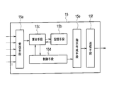
- FIG. 2 is a block diagram showing the internal configuration of the heat source machine controller according to the embodiment of the present invention.
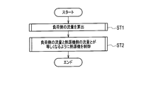
- FIG. 3 is a flowchart showing a rough flow regarding a control method of the secondary pump heat source system according to the embodiment of the present invention.
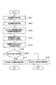
- FIG. 4 is a flowchart showing a flow for calculating the total flow rate of the heat source water flowing on the load facility side in the embodiment of the present invention.
- FIG. 1 is an overall view showing a secondary pump type heat source system according to an embodiment of the present invention.
- FIG. 2 is a block diagram showing the internal configuration of the heat source machine controller according to the embodiment of the present invention.
- FIG. 3 is a flowchart showing a rough flow regarding a control method of the secondary pump heat source system according to the embodiment of the present invention.
- FIG. 4 is a flowchart showing a flow for calculating the total flow rate of the heat source water flowing on
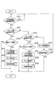
- FIG. 5 is a flowchart showing a flow in which the heat source controller controls the heat source unit so that the total flow rate of the heat source water flowing on the load facility side and the total flow rate of the heat source water flowing on the heat source unit side are equalized in the embodiment of the present invention.
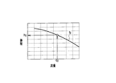
- FIG. 6 is a graph showing the relationship between the average flow rate, the operation frequency, and the three lifts when the lift is obtained from the average flow rate and the operation frequency in the embodiment of the present invention.
- FIG. 7 shows the lift, average flow, and initial frequency 3 when the initial frequency is calculated from the flow per secondary pump when the number of heads and the number of secondary pumps operated is reduced in the embodiment of the present invention. It is a graph showing a person's relationship.
- FIG. 1 is an overall view showing a secondary pump type heat source system S according to an embodiment of the present invention.
- the secondary pump type heat source system S is largely divided into a heat source machine side A and a load facility side B as shown by a broken line in FIG.
- the heat source machine side A is provided with a heat source machine 1 that generates heat source water and a secondary pump (heat source machine side pump) 2 that supplies the heat source water circulated to the heat source machine 1.
- a compressor, a four-way valve, a heat exchanger, a throttle mechanism, and a water heat exchanger are provided in the heat source unit 1 and are connected by piping.
- the piping is filled with a refrigerant, and this refrigerant sequentially circulates through the compressor, the heat exchanger, the throttle mechanism, and the water heat exchanger to form a refrigerant circuit.
- the compressor sucks and compresses the refrigerant, and discharges the high-temperature and high-pressure refrigerant.
- a heat exchanger having a blower at one end is connected to the discharge side of the compressor. In the heat exchanger, the refrigerant exchanges heat with air by the ventilation of the blower.
- a throttle mechanism is further connected to the heat exchanger, and the refrigerant that has passed through the throttle mechanism passes through the water heat exchanger. In the water heat exchanger, the refrigerant exchanges heat with water flowing in a pipe separately connected to the water heat exchanger, and heat source water is generated. Thereafter, the refrigerant enters the compressor again.
- the heat source machine can generate either cooling / cooling cold water or heating / heating hot water.
- the secondary pump 2 that supplies the heat source water to the heat source unit 1 is provided for each heat source unit 1 and is connected to the inverter device 3 for the secondary pump.
- the secondary pump 2 is based on an instruction from the heat source unit controller described later.
- the inverter device 3 is operated at a variable speed.
- the specifications (input-flow rate characteristics) of each secondary pump 2 are the same.
- the capacity of the secondary pump 2 in operation that is, the output of the secondary pump inverter device 3 is controlled to be the same.
- a heat source machine inlet water temperature sensor 4 for measuring the temperature of the heat source water supplied to the heat source machine 1 and a heat source water supplied from the heat source machine 1 to the load facility are respectively provided in the vicinity of the inlet and outlet to the heat source machine 1.
- a heat source machine outlet water temperature sensor 5 for measuring temperature is connected.
- the heat source devices 1 are connected in parallel in FIG. 1 (hereinafter, these heat source devices are collectively referred to as “heat source device 1” unless otherwise required). Any number may be connected as long as the number of connections is at least two.
- the secondary pumps 2 are always connected to the heat source unit 1, the number of installed heat source units 1 and secondary pumps 2 is the same.
- the secondary pump inverter device 3 is connected to the secondary pump 2, and the heat source device inlet water temperature sensor 4 and the heat source device outlet water temperature sensor 5 are connected to the heat source device 1 as described above. Accordingly, the heat source unit 1, the secondary pump 2, the secondary pump inverter device 3, the heat source unit inlet water temperature sensor 4, and the heat source unit outlet water temperature sensor 5 are collectively referred to as a heat source unit as appropriate.
- the heat source water generated in the heat source unit 1 is supplied to the load equipment side B through the water supply pipe 6 whose one end is connected to the outlet of the heat source unit 1.
- a primary pump (load-side pump) 7 and a primary pump inverter device 8 for controlling the primary pump 7 are further connected to the other end of the water supply pipe 6, and heat source water is supplied to the load facility 9.
- the primary pump 7 is driven at a variable speed by the primary pump inverter device 8, and the flow rate of the heat source water supplied to the load facility 9 is controlled.
- the flow rate of the output (flow rate) of the primary pump 7 is controlled irrespective of the operation on the heat source side according to the cooling / heating capacity required by the load facility 9.
- an air conditioner such as a fan coil is applicable.
- the load equipment 9 is connected in parallel in FIG. 1 (hereinafter, these load equipments are collectively referred to as “load equipment 9” unless otherwise required). Any number of connected units may be connected.
- the heat source water subjected to heat exchange in the load facility 9 flows through the return pipe 11 through the two-way valve 10 connected to the outlet side of the load facility 9 and is sent to the secondary pump 2 on the heat source machine side A.
- a water supply temperature sensor 12 that measures the temperature of the heat source water flowing in the water supply pipe 6 is provided. Further, a return water temperature sensor 13 for measuring the temperature of the heat source water flowing in the return water pipe 11 is provided between the load facility 9 and the secondary pump 2.
- a bypass pipe 14 is provided so as to communicate the water supply pipe 6 between the heat source unit 1 and the water supply temperature sensor 12 and the return water pipe 11 between the return water temperature sensor 13 and the secondary pump 2.
- the return water temperature sensor 13 is attached to the return water pipe 11 on the load facility 9 side from the connection part between the return water pipe 11 and the bypass pipe 14, and the water supply temperature sensor 12 is provided from the connection part between the water supply pipe 6 and the bypass pipe 14. It is attached to the water supply pipe 6 on the load facility 9 side.
- the heat source device controller 15 is a controller for controlling the operation of each device installed on the heat source device side A.
- three heat source devices 1 connected to each other are controlled to operate based on an instruction from the heat source device controller 15.
- FIG. 2 is a block diagram showing the internal configuration of the heat source controller 15.
- the heat source controller 15 includes a receiving unit 15a, a storage unit 15b, a calculating unit 15c, a control unit 15d, an instruction creating unit 15e, and a transmitting unit 15f.
- the receiving means 15a includes, for example, each temperature sensor, that is, the water temperature sensor 12, the return water temperature sensor 13, and the water temperature from the heat source unit inlet water temperature sensor 4 and the heat source unit outlet water temperature sensor 5 for each heat source unit via the heat source unit 1. Receive information.
- storage means 15b memorize
- the calculation means 15c applies the measurement result transmitted from each temperature sensor to the formula stored in the storage means 15b, and the flow rate of the heat source water flowing through the heat source machine side A and the flow rate of the heat source water flowing through the load facility side B. Is calculated.
- the control means 15d gives a control instruction to each heat source unit 1 and each secondary pump 2 based on the result calculated by the calculation means 15c.
- the instruction creating unit 15e creates an actual instruction for each heat source unit 1 based on the instruction from the control unit 15d.
- the transmission means 15 f plays a role of transmitting an instruction to each heat source device 1 and the inverter device 3 of each secondary pump 2.
- FIG. 3 is a flowchart showing a rough flow regarding a control method of the secondary pump heat source system S.
- the control of the secondary pump type heat source system S is roughly divided into two stages. That is, first through the step (ST1) of calculating the total flow rate of the heat source water flowing through the load facility side B, based on the calculated flow rate on the heat source device side A and the flow rate on the load facility side B, the heat source device side A Step (ST2) in which the heat source controller 15 determines increase / decrease in the capacity (flow rate) and the number of the secondary pumps 2 so as to reduce the difference between the flow rate and the load facility side B flow rate (ST2). ).
- FIG. 4 is a flowchart for explaining in detail the flow (ST1) for calculating the total flow rate of the heat source water flowing on the load facility side B.
- ST1 the capacity of each heat source unit 1 is calculated (ST11).
- the installed heat source apparatus 1 is not necessarily a device of the same type, and even if the heat source apparatus 1 is of the same type, the capacity of each heat source apparatus 1 is often slightly different. Therefore, first, the capability of each heat source machine 1 is grasped.
- each heat source unit 1 is operated, and the refrigeration or heating capacity is derived from the saturated condensation temperature and saturated evaporation temperature during the operation.
- the heat source unit 1 is experimentally operated in advance, and the operating capacity, saturation condensation temperature, and saturation evaporation temperature at that time are calculated.
- the relationship is expressed in an equation.
- the flow rate of the heat source water flowing through each heat source unit 1 is calculated using the following formula (ST12). That is, the temperature information measured by the heat source unit inlet water temperature sensor 4 and the heat source unit outlet water temperature sensor 5 is received by the receiving unit 15a and transmitted to the calculating unit 15c.
- the calculation means 15c draws the expression stored in the storage means 15b in accordance with the operating state of the heat source unit 1, applies the temperature information measured by the heat source unit inlet water temperature sensor 4 and the heat source unit outlet water temperature sensor 5 to the heat source unit 1
- the flow rate of the heat source water flowing through is calculated. This flow rate is calculated for each heat source unit 1 (heat source unit) connected to the secondary pump type heat source system S. Therefore, it is possible to grasp the flow rate for each heat source unit 1 (heat source unit).
- the heat source unit 1 generates heat source water based on the return water sent from the secondary pump 2. This is because both the heat source unit 1 and the secondary pump 2 are operated. In this case, the flow rate of the heat source water flowing through the heat source unit can be calculated.
- the secondary pump 2 is operated depending on the operation state of the secondary pump type heat source system S from time to time, there may be a heat source unit where the heat source unit 1 is not operated. Such a state occurs when the required capacity on the load equipment side B is reduced. In this case, the amount of heat source water flowing through the heat source unit 1 cannot be calculated because the above-described equation (1) or equation (2) cannot be used.
- the flow rate q calculated in the heat source unit in which both the heat source unit 1 and the secondary pump 2 are operated is added up. Then, by dividing the flow rate obtained by the summation by the number of heat source unit units in which both the heat source unit 1 and the secondary pump 2 are operated, both the heat source unit 1 and the secondary pump 2 are used.
- the average flow rate of the heat source water flowing through the heat source unit 1 of the heat source unit in which is operated can be calculated. This average flow rate is defined as a flow rate q in the heat source unit where the secondary pump 2 is operated but the heat source unit 1 is not operated.
- the secondary pump 2 is operated by the average flow rate of the heat source water flowing through the heat source unit 1 of the operated heat source unit, and this average flow rate is calculated as the flow rate in the heat source unit where the heat source unit 1 is not operated. Even if it assumes, a big error does not occur.
- the flow rate q for each heat source unit 1 (heat source unit) calculated by the calculation unit 15c through the above calculation is further added by the calculation unit 15c, and the total flow rate Q1 of the heat source water flowing through the heat source side A is calculated. Is calculated (ST13).
- the calculation means 15c receives the information regarding the inlet water temperature and the outlet water temperature measured by the heat source machine inlet water temperature sensor 4 and the heat source machine outlet water temperature sensor 5 through the receiving means 15a, and the calculation means 15c calculates them.
- the average of the inlet water temperature and the outlet water temperature of each heat source unit 1 is calculated in this way because it is necessary to calculate the flow rate of the heat source water flowing through the load facility side B without using a flow meter. is there.
- the inlet water temperature and the outlet water temperature used are the heat source machine inlet water temperature sensor 4 and the heat source machine outlet of the heat source machine unit in which the secondary pump 2 is operated regardless of whether the heat source machine 1 is operated.
- the temperature is limited to the temperature measured by the water temperature sensor 5. This is because the heat source water flows through the water pipe 6 and is supplied to the load facility side B if the secondary pump 2 is operated regardless of whether or not the heat source apparatus 1 is operated.
- the average outlet water temperature of each heat source device 1 calculated by the calculation means 15c is transmitted to the control means 15d.
- the control means 15d also collects information related to the water supply temperature measured by the water supply temperature sensor 12.
- the control means 15d compares the average outlet water temperature with the water supply temperature (ST15).
- the heat source water that leaves the heat source unit 1 and flows through the water supply pipe 6 (hereinafter, such heat source water is referred to as “water supply” as appropriate). It can be determined that the flow is directly flowing to the load facility 9 via the primary pump 7. This is because there is naturally a difference between the temperature of the water supply and the return water (the water supply temperature is lower than the return water temperature or the water supply temperature is higher than the return water temperature). Therefore, when the return water flows into the water supply pipe 6 via the bypass pipe 14 (that is, when the return water flows through the bypass pipe 14 shown in FIG. 1 from right to left), the average outlet water temperature and the water supply temperature This is because there is a difference between the two.
- the fact that the average outlet water temperature is equal to the water supply temperature does not always indicate that the amount of heat source water flowing through the heat source machine side A is equal to the amount of heat source water flowing through the load facility side B.
- the amount of heat source water flowing through the heat source apparatus side A is greater than the amount of heat source water flowing through the load facility side B. Even if there are many, the average outlet water temperature is equal to the water supply temperature.
- the water supply flows into the return water pipe 11 via the bypass pipe 14 (that is, the bypass shown in FIG. 1).
- the water flows through the pipe 14 from left to right).
- the total flow rate Q2 of the heat source water flowing through the load facility side B is calculated using the following equation (3).
- the means 15c calculates (ST17).
- the total flow rate Q2 of the heat source water flowing through the load facility side B is the difference between the total flow rate Q1 of the heat source unit side A and the flow rate of the heat source water flowing through the bypass pipe 14.
- the temperature of the heat source water flowing to the heat source unit 1 through the return pipe 11, that is, the temperature measured by the heat source unit inlet water temperature sensor 4 is the return water temperature when the heat source unit 1 is performing a cooling (cooling) operation.
- the temperature is lower than the temperature measured by the sensor 13, and higher than the temperature measured by the return water temperature sensor 13 when the heat source device 1 is performing a heating (heating) operation. Therefore, the following equation is used as shown in “Equation 3”.
- the return water is flowing into the water supply pipe 6 from the return water pipe 11 via the bypass pipe 14, and the load equipment side B is connected. It shows that the total flow rate of the flowing heat source water is larger than the total flow rate of the heat source water flowing on the heat source unit side A. Accordingly, the total flow rate Q2 of the heat source water flowing through the load facility side B is obtained by adding the amount of the heat source water flowing through the bypass pipe 14 to the total flow rate Q1 of the heat source water flowing through the heat source unit side A.
- the calculation means 15c derives the following equation (4) from the storage means 15b, and calculates the total flow rate Q2 of the heat source water flowing through the load facility side B (ST18).
- the total flow rate Q2 of the heat source water flowing through the load facility side B can be calculated.
- the heat source controller 15 causes the secondary pump 2 to reduce the difference between the total flow rate Q2 of the heat source water flowing through the load facility side B and the total flow rate Q1 of the heat source water flowing through the heat source side A.
- a method of determining and controlling the increase / decrease in the number of units will be described. This is the stage of step 2 shown in FIG. 3, and is specifically performed according to the procedure shown in the flowchart of FIG.
- the control means 15d first determines whether or not the total flow rate Q2 of the heat source water flowing through the load facility side B is equal to the total flow rate Q1 of the heat source water flowing through the heat source unit side A (ST21).
- ST21 total flow rate Q2 of the heat source water flowing through the load facility side B and the total flow rate Q1 of the heat source water flowing through the heat source unit A are equal (YES in ST21)
- the heat source controller 15 controls the secondary pump 2 so as to maintain this state.
- the stage-down condition nor the stage-increase condition is satisfied. After all, it is only necessary to adjust the operation frequency of the secondary pump 2 without increasing / decreasing the number of secondary pumps 2 operated.
- the total flow rate of the heat source water flowing through the side A can be made equal to the total flow rate of the heat source water flowing through the load facility side B.
- the heat source device 1 can be efficiently and appropriately operated according to the requirements of the load facility 9. It shows that it is possible.
- the secondary pumps 2 are increased or decreased with the same operating frequency of each of the secondary pumps 2 being operated.
- the control means 15d adjusts the frequency based on the output frequency of the secondary pump inverter device 3 currently used for the operation of the secondary pump 2. This adjustment may not be completed once (NO in ST25). In this case, the frequency adjustment is repeated until an appropriate frequency is determined.
- PID control or the like is preferably used.
- examples of conditions for reducing the number of pumps include the following conditions.
- the secondary pump 2 is operated but the compressor in the heat source unit 1 is not operated, and there is a heat source unit in which the heat source unit 1 is stopped.
- the indicated frequency to the secondary pump 2 is operated. The lowest possible frequency is reached, and the flow rate per heat source unit 1 is the minimum flow rate of the heat source unit 1.
- the secondary pump 2 is operated only to secure the flow rate. There is no problem even if it is stopped.
- the secondary pump 2 is switched on in ST24. This is because the flow rate can be reduced by reducing the frequency.
- both of the two pump number reduction conditions are When it is satisfied, the number of secondary pumps 2 is reduced.
- the pump number reduction condition is merely given as an example, and can be arbitrarily set depending on the state of the secondary pump installed in the secondary pump heat source system S.
- the calculation means 15c calculates the frequency (initial frequency) used when operating each heat source unit 1 after reducing the number of pumps. This initial frequency is calculated according to the following procedure.
- the total flow rate Q1 of the heat source water flowing through the heat source machine side A is divided by the number of operating secondary pumps 2 operated at the time of calculation. Thereby, the flow rate (average flow rate q0) per unit of the operated secondary pumps 2 is calculated.
- the head h0 of the heat source unit 1 is calculated from the calculated average flow rate q0 and the operating frequency f0 of the secondary pump 2 at the time of calculation.
- FIG. 6 is a graph showing a three-way relationship between the average flow rate q0, the operation frequency f0, and the lift h0 when the lift h0 is obtained from the average flow rate q0 and the operation frequency f0.
- the vertical axis indicates the head and the horizontal axis indicates the flow rate.
- the storage unit 15b may store an approximate expression for drawing this graph, or may store it in a tabular table step by step. As shown in FIG. 6, if the average flow rate q0 and the operation frequency f0 are known, the head h0 of the heat source unit 1 can be calculated.
- the reason why the “lift” is used when calculating the initial frequency is as follows.
- the plurality of secondary pumps 2 installed on the heat source apparatus side A are all operated using the same frequency. This is because if the operation frequency is different for each secondary pump 2, a difference occurs in the performance, and it is very difficult to control, and it is difficult to perform smooth operation control, resulting in inefficient operation.
- the number of heat source units 1 is increased or decreased, if the same frequency as the previous operating frequency is used for the operation of the heat source unit 1, the supply of heat source water that accurately corresponds to the change on the load facility side B Can not do.
- the total flow rate of the heat source water flowing through the heat source machine side A does not change.
- the fact that the total flow rate of the heat source water does not change does not change the resistance in the water supply pipe 6 and the return water pipe 11 and does not change the head required for the secondary pump 2.
- the operation control of the secondary pump 2 can be smoothly performed using a frequency that can accurately cope with an operation change on the load facility side B.
- the head h0 of the heat source unit 1 can be calculated based on the intersection with the operating frequency f0.
- the flow rate of the heat source water flowing through each secondary pump 2 is calculated.
- the operating number obtained by subtracting 1 from the original number of operating secondary pumps 2 is set as the number of operating units using the initial frequency.
- the secondary operated using the initial frequency is divided by dividing the total flow rate Q1 of the heat source water flowing through the heat source machine side A by the number of operating units obtained by subtracting 1 from the number of operating units of the original secondary pump 2.
- the flow rate q1 per pump 2 can be obtained.
- the control means 15d determines the secondary pump 2 whose operation is to be stopped. Then, the instruction creating unit 15e is instructed to transmit the pump stage reduction instruction to the corresponding heat source unit. Based on this instruction, the instruction creating unit 15e transmits a step-down instruction to the corresponding heat source unit via the transmitting unit 15f (ST28).
- the initial frequency f1 calculated by the calculation unit 15c is set to the secondary pump 2 via the control unit 15d, the instruction generation unit 15e, and the transmission unit 15f.
- the secondary pump 2 is operated at the transmitted initial frequency f1.
- the control means 15d instructs the calculation means 15c to calculate the frequency (initial frequency) used when operating each heat source unit 1 after increasing the number of pumps (ST31). If there is no secondary pump 2 that is stopped among the secondary pumps 2, the current operation is continued as it is (NO in ST30).
- the reason for confirming that there are secondary pumps 2 being stopped is that if there are no secondary pumps 2 being stopped, the number of operating secondary pumps 2 cannot be increased even if the conditions for increasing the number of pumps are satisfied. It is.
- conditions for increasing the number of pumps include the following conditions.
- the operating capacities of all the heat source units 1 in which the secondary pumps 2 are operated exceed the maximum efficiency point, and the flow rate of the heat source water per heat source unit does not fall below the minimum flow rate even if the number of pumps increases.
- the instruction frequency to the secondary pump 2 reaches the maximum operable frequency, and the flow rate per unit of the heat source unit 1 is the maximum flow rate of the heat source unit 1.
- At least one secondary pump 2 is stopped at the time of determining whether or not the above-mentioned pump number increase condition is satisfied. When either of them is satisfied, the number of secondary pumps 2 is increased.
- the conditions for increasing the number of pumps are merely examples, and can be arbitrarily set depending on the state of the secondary pumps installed in the secondary pump type heat source system S.
- the calculation means 15c calculates the frequency (initial frequency) used when operating each secondary pump 2 after increasing the number of pumps. This initial frequency is the same as the calculation method under the above-described conditions for reducing the number of pumps.
- the total flow rate Q1 of the heat source water flowing through the heat source machine side A is divided by the number of operating secondary pumps 2 operated at the time of calculation. Thereby, the flow rate (average flow rate q0) per unit of the operated secondary pumps 2 is calculated.
- the head h0 of the heat source unit 1 is calculated from the calculated average flow rate q0 and the operating frequency f0 of the secondary pump 2 at the time of calculation.
- the flow rate q1 of the heat source water flowing through each secondary pump 2 when the number of pumps increases is obtained.
- the secondary operated using the initial frequency is divided by dividing the total flow rate Q1 of the heat source water flowing through the heat source machine side A by the number of operating secondary pumps 2 plus one.
- the flow rate q1 per pump 2 can be obtained.
- the initial frequency f1 used for the operation of each secondary pump 2 when the number of operating secondary pumps 2 increases from the head h0 and the flow rate q1 is calculated.
- the control means 15d determines the heat source unit that starts the operation.
- the instruction creating unit 15e is instructed to transmit the stage increase instruction of the secondary pump 2 to the corresponding heat source unit. Based on this instruction, the instruction creating means 15e transmits a stage increase instruction to the corresponding heat source unit via the transmitting means 15f (ST32).
- the initial frequency f1 calculated by the calculation unit 15c is set to each secondary pump 2 via the control unit 15d, the instruction generation unit 15e, and the transmission unit 15f.
- the secondary pump 2 is operated at this initial frequency f1.
- a secondary pump system that can respond appropriately to changes on the load equipment side without installing an expensive flow meter, and can contribute to energy saving by performing highly efficient control.
- a heat source system and a secondary pump heat source control method can be provided.
- the entire system can be constructed at low cost.
- heat source control that can always respond accurately to changes on the load equipment side can be performed using the calculated flow rate of the heat source water flowing on the heat source equipment side and the load equipment side.
- the heat source machine that contributes can be operated.
- the present invention is not limited to the above-described embodiment as it is, and can be embodied by modifying the constituent elements without departing from the scope of the invention in the implementation stage.
- Various inventions can be formed by appropriately combining a plurality of constituent elements disclosed in the above embodiments. For example, some components may be deleted from all the components shown in the embodiment. Furthermore, you may combine the component covering different embodiment suitably.
- the embodiments of the present invention have been described above, but only specific examples have been illustrated, and the present invention is not particularly limited. Specific configurations and the like of each part can be appropriately changed. Further, the actions and effects described in the embodiments only list the most preferable actions and effects resulting from the present invention, and the actions and effects according to the present invention are limited to those described in the embodiments of the present invention. Is not to be done.
- the present invention is used in a place where it is necessary to air-condition a plurality of air-conditioning areas such as a large-scale factory or building.
Landscapes
- Engineering & Computer Science (AREA)
- Mechanical Engineering (AREA)
- General Engineering & Computer Science (AREA)
- Chemical & Material Sciences (AREA)
- Combustion & Propulsion (AREA)
- Physics & Mathematics (AREA)
- Thermal Sciences (AREA)
- Air Conditioning Control Device (AREA)
- Other Air-Conditioning Systems (AREA)
Abstract
Description




Claims (5)
- 熱源水を生成する並列接続された複数の熱源機と、
前記熱源水が流通する負荷設備と、
前記熱源水を前記負荷設備に供給する一次ポンプと、
前記熱源機の出口側と前記負荷設備とを接続する送水管と、
前記各熱源機ごとに設けられ、前記負荷設備において熱交換された前記熱源水を前記熱源機へ供給する二次ポンプと、
前記負荷設備の出口側と前記二次ポンプとを接続する還水管と、
前記送水管と、前記還水管とを連通するバイパス管と、
前記熱源水の温度を検出する水温センサと、
前記水温センサの計測結果を個々の前記熱源機の運転特性に当て嵌めて前記熱源機側の流量及び前記負荷設備側を流れる前記熱源水の流量を算出し、この算出結果に基づいて前記二次ポンプの動作を制御する前記熱源機コントローラと、
を備えることを特徴とする二次ポンプ方式熱源システム。 - 前記水温センサは、前記熱源機と前記負荷設備との間において、前記送水管内を流れる前記熱源水の温度を計測する送水温度センサと、前記負荷設備と前記二次ポンプとの間において、前記還水管内を流れる前記熱源水の温度を計測する還水温度センサと、前記熱源機の入口において前記熱源機に供給される前記熱源水の温度を計測する熱源機入口水温センサと、前記熱源機の出口において前記熱源機から前記負荷設備に供給される前記熱源水の温度を計測する熱源機出口水温センサとからなり、
前記熱源機コントローラは、
制御する前記熱源機の個々の運転特性を記憶する記憶手段と、
前記送水温度センサと、前記還水温度センサと、前記熱源機入口水温センサと、前記熱源機出口水温センサの計測結果を前記記憶手段内に記憶されている前記運転特性に当て嵌めて前記熱源機側の流量及び前記負荷設備側を流れる前記熱源水の流量を算出する算出手段と、
前記算出手段によって算出された結果に基づいて前記二次ポンプの動作を制御する制御手段と、
を備えることを特徴とする請求項1記載の二次ポンプ方式熱源システム。 - 熱源水を生成する並列接続された複数の熱源機と、
前記熱源水が流通する負荷設備と、
前記熱源水を前記負荷設備に供給する一次ポンプと、
前記熱源機の出口側と前記負荷設備とを接続する送水管と、
前記各熱源機ごとに設けられ、前記負荷設備において熱交換された前記熱源水を前記各熱源機へ供給する二次ポンプと、
前記負荷設備の出口側と前記二次ポンプとを接続する還水管と、
前記送水管と前記還水管とを連通するバイパス管とを備えた二次ポンプ方式熱源制御方法において、
前記熱源水の温度に基づき前記熱源機側を流れる熱源水の流量と、前記負荷設備側を流れる熱源水の流量とを算出するステップと、
算出された前記熱源機側流量と前記負荷設備側流量に基づいて、前記熱源機側流量と前記負荷設備側流量との差異を小さくするように前記二次ポンプの台数の増減を決定し、制御するステップと、
を備えることを特徴とする二次ポンプ方式熱源制御方法。 - 前記負荷設備側を流れる熱源水の流量を算出するステップは、
前記熱源機の個々の能力を算出するステップと、
前記算出された前記熱源機の個々の能力と、前記熱源機の入口において前記熱源機に供給される前記熱源水の温度を計測する熱源機入口水温センサと前記熱源機の出口において前記熱源機から前記負荷設備に供給される前記熱源水の温度を計測する熱源機出口水温センサとから得られた結果を基に前記熱源機の流量を算出するステップと、
前記算出された前記熱源機の流量を合わせて前記熱源機側を流れる熱源水の総流量を算出するステップと、
全ての前記熱源機入口水温センサから得られた水温を平均し、全ての前記熱源機出口水温センサから得られた水温を平均するステップと、
平均化された前記熱源機出口水温と、前記熱源機と前記一次ポンプとの間において、前記送水管内を流れる前記熱源水の温度を計測する送水温度センサによって計測された送水温度とを比較するステップと、
平均化された前記熱源機出口水温と前記送水温度とが等しい場合には、前記熱源機側を流れる熱源水の総流量と、平均化された前記熱源機入口水温と、平均化された前記熱源機出口水温と、前記負荷設備と前記二次ポンプとの間において、前記還水管内を流れる前記熱源水の温度を計測する還水温度センサによって計測された還水温度とを用いて、前記負荷設備側を流れる熱源水の流量を求めるステップと、
平均化された前記熱源機出口水温よりも前記送水温度が高い場合には、前記熱源機側を流れる熱源水の総流量と、平均化された前記熱源機入口水温と、平均化された前記熱源機出口水温と、前記送水温度と、前記還水温度とを用いて、前記負荷設備側を流れる熱源水の流量を求めるステップと、
を備えることを特徴とする請求項3に記載の二次ポンプ方式熱源制御方法。 - 前記熱源機コントローラが、周波数によって前記熱源水の供給能力を変化させる前記二次ポンプを制御するステップは、
前記熱源機側を流れる熱源水の流量と前記負荷設備側を流れる熱源水の流量とが等しいか否かを判断するステップと、
前記熱源機側を流れる熱源水の流量と前記負荷設備側を流れる熱源水の流量とが等しくない場合に、二次ポンプの台数を減段させるための条件を充足するか否かを判断するステップと、
前記減段条件が充足される場合に、減段時における残りの前記二次ポンプを駆動するための周波数を算出するステップと、
前記算出された減段時の周波数を用いて前記二次ポンプを駆動するステップと、
前記減段条件が充足されない場合に、さらに前記二次ポンプの台数を増段させるための条件を充足するか否かを判断するステップと、
前記増段条件が充足される場合に、休止している前記二次ポンプを確認するとともに増段時における前記二次ポンプを駆動するための周波数を算出するステップと、
前記算出された増段時の周波数を用いて前記二次ポンプを駆動するステップと、
前記減段条件及び前記増段条件が充足されない場合に、前記二次ポンプを駆動するための周波数を調整するステップと、
を備えることを特徴とする請求項4に記載の二次ポンプ方式熱源制御方法。
Priority Applications (7)
| Application Number | Priority Date | Filing Date | Title |
|---|---|---|---|
| KR1020117021271A KR101244536B1 (ko) | 2009-02-13 | 2010-02-08 | 2차 펌프 방식 열원 시스템 및 2차 펌프 방식 열원 제어 방법 |
| RU2011137550/12A RU2490561C2 (ru) | 2009-02-13 | 2010-02-08 | Система источника тепла со вспомогательными насосами и способ управления источником тепла со вспомогательными насосами |
| EP10741193.6A EP2397786B1 (en) | 2009-02-13 | 2010-02-08 | Secondary pump type heat source system and secondary pump type heat source control method |
| JP2010550501A JP4975168B2 (ja) | 2009-02-13 | 2010-02-08 | 二次ポンプ方式熱源システム及び二次ポンプ方式熱源制御方法 |
| BRPI1008786-9A BRPI1008786B1 (pt) | 2009-02-13 | 2010-02-08 | sistema de fonte de calor do tipo bomba secundária e método de controle de fonte de calor do tipo bomba secundária |
| US13/201,192 US8939196B2 (en) | 2009-02-13 | 2010-02-08 | Secondary pump type heat source and secondary pump type heat source control method |
| CN201080007680.XA CN102308155B (zh) | 2009-02-13 | 2010-02-08 | 二次泵式热源系统及二次泵式热源控制方法 |
Applications Claiming Priority (2)
| Application Number | Priority Date | Filing Date | Title |
|---|---|---|---|
| JP2009-031116 | 2009-02-13 | ||
| JP2009031116 | 2009-02-13 |
Publications (1)
| Publication Number | Publication Date |
|---|---|
| WO2010092916A1 true WO2010092916A1 (ja) | 2010-08-19 |
Family
ID=42561758
Family Applications (1)
| Application Number | Title | Priority Date | Filing Date |
|---|---|---|---|
| PCT/JP2010/051755 Ceased WO2010092916A1 (ja) | 2009-02-13 | 2010-02-08 | 二次ポンプ方式熱源システム及び二次ポンプ方式熱源制御方法 |
Country Status (10)
| Country | Link |
|---|---|
| US (1) | US8939196B2 (ja) |
| EP (1) | EP2397786B1 (ja) |
| JP (1) | JP4975168B2 (ja) |
| KR (1) | KR101244536B1 (ja) |
| CN (1) | CN102308155B (ja) |
| BR (1) | BRPI1008786B1 (ja) |
| HU (1) | HUE043923T2 (ja) |
| RU (1) | RU2490561C2 (ja) |
| TR (1) | TR201902393T4 (ja) |
| WO (1) | WO2010092916A1 (ja) |
Cited By (8)
| Publication number | Priority date | Publication date | Assignee | Title |
|---|---|---|---|---|
| JP2011064438A (ja) * | 2009-09-18 | 2011-03-31 | Hitachi Cable Ltd | 冷水循環システム |
| JP2011231955A (ja) * | 2010-04-26 | 2011-11-17 | Hitachi Appliances Inc | 冷凍システム |
| JP2012247122A (ja) * | 2011-05-27 | 2012-12-13 | Mitsubishi Electric Corp | 冷凍サイクル装置 |
| JP2014035102A (ja) * | 2012-08-07 | 2014-02-24 | Daikin Ind Ltd | 空調システム |
| WO2015190525A1 (ja) * | 2014-06-10 | 2015-12-17 | 東芝キヤリア株式会社 | 熱源機および熱源装置 |
| JP2017067338A (ja) * | 2015-09-29 | 2017-04-06 | 三機工業株式会社 | 熱媒体配管システム又は熱媒体配管システムにおける熱媒体搬送システム |
| US9759457B1 (en) * | 2012-10-16 | 2017-09-12 | Amazon Technologies, Inc. | Controls solution for primary-secondary chiller plant |
| EP4438968A4 (en) * | 2021-12-28 | 2024-11-27 | Mitsubishi Heavy Industries Thermal Systems, Ltd. | HEAT SOURCE SYSTEM, ITS CONTROL METHOD AND PROGRAM |
Families Citing this family (22)
| Publication number | Priority date | Publication date | Assignee | Title |
|---|---|---|---|---|
| US11536507B2 (en) * | 2011-11-17 | 2022-12-27 | Optimum Energy, Llc | Systems and methods for reducing energy consumption of a chilled water distribution system |
| JP5932419B2 (ja) * | 2012-03-21 | 2016-06-08 | 株式会社東芝 | 熱回収プラントシステム、熱回収プラント制御装置および熱回収プラント制御方法 |
| JP5447627B1 (ja) * | 2012-09-26 | 2014-03-19 | ダイキン工業株式会社 | 熱源システム制御装置 |
| US9562708B2 (en) | 2012-12-03 | 2017-02-07 | Waterfurnace International, Inc. | Conduit module coupled with heating or cooling module |
| JP6210219B2 (ja) * | 2014-01-31 | 2017-10-11 | 三菱重工サーマルシステムズ株式会社 | ポンプ台数制御方法、ポンプ台数制御装置、ポンプシステム、熱源システム及びプログラム |
| KR101805334B1 (ko) * | 2014-02-20 | 2017-12-05 | 도시바 캐리어 가부시키가이샤 | 열원 장치 |
| JP6271316B2 (ja) * | 2014-03-27 | 2018-01-31 | 荏原冷熱システム株式会社 | 熱源装置 |
| WO2015162798A1 (ja) * | 2014-04-25 | 2015-10-29 | 三菱電機株式会社 | ヒートポンプチリングシステム及びその制御方法 |
| US10161639B2 (en) * | 2015-03-10 | 2018-12-25 | Joseph Copeland | Heat transfer apparatus and heat transfer system for masonry heater |
| CN104964398A (zh) * | 2015-07-16 | 2015-10-07 | 珠海格力电器股份有限公司 | 空调系统的流量控制方法及装置 |
| CN105865105B (zh) * | 2016-03-30 | 2019-01-15 | 北京百度网讯科技有限公司 | 冷冻水二次泵系统的控制方法和装置 |
| JP6609697B2 (ja) * | 2016-05-27 | 2019-11-20 | 東芝キヤリア株式会社 | 熱源システム、及び熱源システムの制御方法 |
| RU2659993C1 (ru) * | 2017-08-28 | 2018-07-04 | Общество с ограниченной ответственностью "Научно-технический комплекс "Криогенная техника" | Способ управления системой поддержания температурно-влажностного режима |
| CN108534210B (zh) * | 2018-06-14 | 2023-12-01 | 济南金孚瑞供热工程技术有限公司 | 叠加式蓄能型热泵供热系统的实施方法 |
| EP4148343A4 (en) * | 2018-07-09 | 2024-03-06 | Toshiba Carrier Corporation | HEAT SOURCE SYSTEM, HEAT SOURCE MACHINE AND CONTROL DEVICE |
| US11592215B2 (en) | 2018-08-29 | 2023-02-28 | Waterfurnace International, Inc. | Integrated demand water heating using a capacity modulated heat pump with desuperheater |
| US20200208927A1 (en) | 2018-12-27 | 2020-07-02 | Trane International Inc. | Fluid control for a variable flow fluid circuit in an hvacr system |
| EP3966511B1 (en) | 2019-02-06 | 2025-10-08 | Jeffrey A. Weston | Hydronic system and methods of operation |
| CN111795481B (zh) * | 2019-04-08 | 2023-05-23 | 开利公司 | 空气调节系统及用于其的控制方法 |
| CN111918523B (zh) * | 2020-06-28 | 2023-05-09 | 北京百度网讯科技有限公司 | 制冷系统、制冷系统的控制方法、设备及存储介质 |
| CN111912060A (zh) * | 2020-07-15 | 2020-11-10 | 四川省建筑科学研究院有限公司 | 一种集中空调系统水力平衡自动调适方法及系统 |
| CN114877421B (zh) * | 2022-04-21 | 2023-08-29 | 珠海格力机电工程有限公司 | 空调水系统、控制方法及空调机组 |
Citations (7)
| Publication number | Priority date | Publication date | Assignee | Title |
|---|---|---|---|---|
| JPS61225534A (ja) * | 1985-03-29 | 1986-10-07 | Tokyo Gas Co Ltd | 冷温水機の運転台数制御方法 |
| JPH02219940A (ja) * | 1989-02-21 | 1990-09-03 | Osaka Gas Co Ltd | 冷房又は暖房用装置 |
| JP2004101104A (ja) | 2002-09-11 | 2004-04-02 | Yamatake Corp | 2次ポンプ方式熱源変流量制御方法および2次ポンプ方式熱源システム |
| JP2005337594A (ja) * | 2004-05-27 | 2005-12-08 | Sanki Eng Co Ltd | 空調用熱源システム |
| JP2006132918A (ja) * | 2004-10-06 | 2006-05-25 | Matsushita Electric Ind Co Ltd | 空調装置及びその制御方法 |
| JP2006275397A (ja) | 2005-03-29 | 2006-10-12 | Toyo Netsu Kogyo Kk | 空調システムの冷温水制御方法 |
| JP2008241326A (ja) * | 2007-03-26 | 2008-10-09 | Shin Nippon Air Technol Co Ltd | 配管系設備における流量測定方法 |
Family Cites Families (17)
| Publication number | Priority date | Publication date | Assignee | Title |
|---|---|---|---|---|
| US3202208A (en) * | 1962-08-22 | 1965-08-24 | American Hydrotherm Corp | Heat exchange system with automatic pump control |
| US4482006A (en) * | 1980-09-02 | 1984-11-13 | Anderson Cary R | Thermal energy meter |
| SE8006391L (sv) * | 1980-09-12 | 1982-03-13 | Jacob Weitman | Sett att reglera en vermevexlare |
| US4463574A (en) * | 1982-03-15 | 1984-08-07 | Honeywell Inc. | Optimized selection of dissimilar chillers |
| US4483152A (en) * | 1983-07-18 | 1984-11-20 | Butler Manufacturing Company | Multiple chiller control method |
| SU1260644A1 (ru) * | 1984-12-10 | 1986-09-30 | Алтайский научно-исследовательский и проектно-технологический институт животноводства | Устройство дл регулировани расхода воздуха |
| DE68914142T2 (de) * | 1988-01-19 | 1994-07-07 | Multistack Int Pty Ltd | Heiz- und kühlsysteme. |
| SU1751610A1 (ru) * | 1990-01-11 | 1992-07-30 | Дальневосточный политехнический институт им.В.В.Куйбышева | Способ вентил ции помещений |
| US5138845A (en) * | 1991-04-09 | 1992-08-18 | Brdg-Tndr Corporation | Method and apparatus for controlling the flow of process fluids |
| JPH05223318A (ja) * | 1991-09-02 | 1993-08-31 | Sanden Corp | 水熱源ヒ−トポンプ式空気調和機の流量表示システム |
| US5946926A (en) * | 1998-04-07 | 1999-09-07 | Hartman; Thomas B. | Variable flow chilled fluid cooling system |
| JP4248099B2 (ja) * | 1999-09-21 | 2009-04-02 | 荏原冷熱システム株式会社 | 冷凍機又は冷温水機の制御方法 |
| WO2004005812A1 (en) * | 2002-07-08 | 2004-01-15 | Danfoss A/S | A method and a device for detecting flash gas |
| US7028768B2 (en) * | 2003-08-20 | 2006-04-18 | Itt Manufacturing Enterprises, Inc. | Fluid heat exchange control system |
| JP2006162101A (ja) * | 2004-12-03 | 2006-06-22 | Hitachi Home & Life Solutions Inc | ヒートポンプ給湯装置 |
| JP2009030821A (ja) | 2007-07-24 | 2009-02-12 | Yamatake Corp | 送水制御システムおよび送水制御方法 |
| CN201152584Y (zh) * | 2007-12-04 | 2008-11-19 | 广州迪森家用锅炉制造有限公司 | 一种水—水采暖温度调节器和热水器 |
-
2010
- 2010-02-08 JP JP2010550501A patent/JP4975168B2/ja active Active
- 2010-02-08 EP EP10741193.6A patent/EP2397786B1/en active Active
- 2010-02-08 RU RU2011137550/12A patent/RU2490561C2/ru not_active IP Right Cessation
- 2010-02-08 CN CN201080007680.XA patent/CN102308155B/zh active Active
- 2010-02-08 TR TR2019/02393T patent/TR201902393T4/tr unknown
- 2010-02-08 WO PCT/JP2010/051755 patent/WO2010092916A1/ja not_active Ceased
- 2010-02-08 US US13/201,192 patent/US8939196B2/en active Active
- 2010-02-08 BR BRPI1008786-9A patent/BRPI1008786B1/pt active IP Right Grant
- 2010-02-08 KR KR1020117021271A patent/KR101244536B1/ko active Active
- 2010-02-08 HU HUE10741193A patent/HUE043923T2/hu unknown
Patent Citations (7)
| Publication number | Priority date | Publication date | Assignee | Title |
|---|---|---|---|---|
| JPS61225534A (ja) * | 1985-03-29 | 1986-10-07 | Tokyo Gas Co Ltd | 冷温水機の運転台数制御方法 |
| JPH02219940A (ja) * | 1989-02-21 | 1990-09-03 | Osaka Gas Co Ltd | 冷房又は暖房用装置 |
| JP2004101104A (ja) | 2002-09-11 | 2004-04-02 | Yamatake Corp | 2次ポンプ方式熱源変流量制御方法および2次ポンプ方式熱源システム |
| JP2005337594A (ja) * | 2004-05-27 | 2005-12-08 | Sanki Eng Co Ltd | 空調用熱源システム |
| JP2006132918A (ja) * | 2004-10-06 | 2006-05-25 | Matsushita Electric Ind Co Ltd | 空調装置及びその制御方法 |
| JP2006275397A (ja) | 2005-03-29 | 2006-10-12 | Toyo Netsu Kogyo Kk | 空調システムの冷温水制御方法 |
| JP2008241326A (ja) * | 2007-03-26 | 2008-10-09 | Shin Nippon Air Technol Co Ltd | 配管系設備における流量測定方法 |
Non-Patent Citations (1)
| Title |
|---|
| See also references of EP2397786A4 |
Cited By (11)
| Publication number | Priority date | Publication date | Assignee | Title |
|---|---|---|---|---|
| JP2011064438A (ja) * | 2009-09-18 | 2011-03-31 | Hitachi Cable Ltd | 冷水循環システム |
| JP2011231955A (ja) * | 2010-04-26 | 2011-11-17 | Hitachi Appliances Inc | 冷凍システム |
| JP2012247122A (ja) * | 2011-05-27 | 2012-12-13 | Mitsubishi Electric Corp | 冷凍サイクル装置 |
| JP2014035102A (ja) * | 2012-08-07 | 2014-02-24 | Daikin Ind Ltd | 空調システム |
| US9759457B1 (en) * | 2012-10-16 | 2017-09-12 | Amazon Technologies, Inc. | Controls solution for primary-secondary chiller plant |
| WO2015190525A1 (ja) * | 2014-06-10 | 2015-12-17 | 東芝キヤリア株式会社 | 熱源機および熱源装置 |
| KR20170018890A (ko) * | 2014-06-10 | 2017-02-20 | 도시바 캐리어 가부시키가이샤 | 열원기 및 열원 장치 |
| JPWO2015190525A1 (ja) * | 2014-06-10 | 2017-04-20 | 東芝キヤリア株式会社 | 熱源機および熱源装置 |
| KR101895175B1 (ko) | 2014-06-10 | 2018-09-04 | 도시바 캐리어 가부시키가이샤 | 열원기 및 열원 장치 |
| JP2017067338A (ja) * | 2015-09-29 | 2017-04-06 | 三機工業株式会社 | 熱媒体配管システム又は熱媒体配管システムにおける熱媒体搬送システム |
| EP4438968A4 (en) * | 2021-12-28 | 2024-11-27 | Mitsubishi Heavy Industries Thermal Systems, Ltd. | HEAT SOURCE SYSTEM, ITS CONTROL METHOD AND PROGRAM |
Also Published As
| Publication number | Publication date |
|---|---|
| JPWO2010092916A1 (ja) | 2012-08-16 |
| EP2397786B1 (en) | 2018-11-21 |
| CN102308155B (zh) | 2014-01-08 |
| US20120055665A1 (en) | 2012-03-08 |
| CN102308155A (zh) | 2012-01-04 |
| KR101244536B1 (ko) | 2013-03-18 |
| EP2397786A1 (en) | 2011-12-21 |
| EP2397786A4 (en) | 2017-02-01 |
| TR201902393T4 (tr) | 2019-03-21 |
| RU2011137550A (ru) | 2013-03-20 |
| JP4975168B2 (ja) | 2012-07-11 |
| KR20110126688A (ko) | 2011-11-23 |
| HUE043923T2 (hu) | 2019-09-30 |
| RU2490561C2 (ru) | 2013-08-20 |
| BRPI1008786B1 (pt) | 2020-11-24 |
| US8939196B2 (en) | 2015-01-27 |
| BRPI1008786A2 (pt) | 2016-03-15 |
Similar Documents
| Publication | Publication Date | Title |
|---|---|---|
| JP4975168B2 (ja) | 二次ポンプ方式熱源システム及び二次ポンプ方式熱源制御方法 | |
| JP6414354B1 (ja) | 空調システム | |
| US9995517B2 (en) | Operation control apparatus of air-conditioning apparatus and air-conditioning apparatus comprising same | |
| US10203136B2 (en) | Air conditioning system and method for controlling same | |
| CN104246395B (zh) | 制冷循环装置 | |
| US20130274948A1 (en) | Heat source system and method for controlling the number of operated devices in heat source system | |
| JP5204987B2 (ja) | 空調システムおよび空調システムの制御方法 | |
| CN101354170A (zh) | 空调控制系统及空调控制方法 | |
| JP6609697B2 (ja) | 熱源システム、及び熱源システムの制御方法 | |
| JP4832960B2 (ja) | 水熱源ヒートポンプユニットシステムの制御方法 | |
| US20050155361A1 (en) | Air conditioning system and method for controlling the same | |
| KR101611315B1 (ko) | 공기조화기 및 그 동작방법 | |
| JP5677198B2 (ja) | 空冷ヒートポンプチラー | |
| JP2016102636A (ja) | 空調システム | |
| JP7502693B2 (ja) | 冷凍サイクル装置 | |
| JP5318446B2 (ja) | 外気取入システム | |
| JP7500143B2 (ja) | 空調システムにおける熱源機の制御装置及び制御方法及びプログラム | |
| JP5285925B2 (ja) | 空調システム | |
| JP6507598B2 (ja) | 空調システム | |
| EP4737813A1 (en) | Air conditioner, heat source module, indoor unit, and method for controlling air conditioner | |
| JP2006266566A (ja) | 2ポンプ方式熱源設備の運転制御方法 | |
| JP7011194B2 (ja) | 冷凍サイクル装置 | |
| JP2024141983A (ja) | 空気調和機 | |
| JPH04273955A (ja) | 多室型空気調和機 |
Legal Events
| Date | Code | Title | Description |
|---|---|---|---|
| WWE | Wipo information: entry into national phase |
Ref document number: 201080007680.X Country of ref document: CN |
|
| 121 | Ep: the epo has been informed by wipo that ep was designated in this application |
Ref document number: 10741193 Country of ref document: EP Kind code of ref document: A1 |
|
| WWE | Wipo information: entry into national phase |
Ref document number: 2010550501 Country of ref document: JP |
|
| WWE | Wipo information: entry into national phase |
Ref document number: 2010741193 Country of ref document: EP |
|
| NENP | Non-entry into the national phase |
Ref country code: DE |
|
| WWE | Wipo information: entry into national phase |
Ref document number: 6405/CHENP/2011 Country of ref document: IN |
|
| ENP | Entry into the national phase |
Ref document number: 20117021271 Country of ref document: KR Kind code of ref document: A |
|
| WWE | Wipo information: entry into national phase |
Ref document number: 2011137550 Country of ref document: RU |
|
| WWE | Wipo information: entry into national phase |
Ref document number: 13201192 Country of ref document: US |
|
| REG | Reference to national code |
Ref country code: BR Ref legal event code: B01A Ref document number: PI1008786 Country of ref document: BR |
|
| ENP | Entry into the national phase |
Ref document number: PI1008786 Country of ref document: BR Kind code of ref document: A2 Effective date: 20110815 |