WO2010114083A1 - 熱延鋼板の冷却装置 - Google Patents
熱延鋼板の冷却装置 Download PDFInfo
- Publication number
- WO2010114083A1 WO2010114083A1 PCT/JP2010/055991 JP2010055991W WO2010114083A1 WO 2010114083 A1 WO2010114083 A1 WO 2010114083A1 JP 2010055991 W JP2010055991 W JP 2010055991W WO 2010114083 A1 WO2010114083 A1 WO 2010114083A1
- Authority
- WO
- WIPO (PCT)
- Prior art keywords
- cooling
- nozzle
- hot
- rolled steel
- steel sheet
- Prior art date
- Legal status (The legal status is an assumption and is not a legal conclusion. Google has not performed a legal analysis and makes no representation as to the accuracy of the status listed.)
- Ceased
Links
Images





Classifications
-
- B—PERFORMING OPERATIONS; TRANSPORTING
- B21—MECHANICAL METAL-WORKING WITHOUT ESSENTIALLY REMOVING MATERIAL; PUNCHING METAL
- B21B—ROLLING OF METAL
- B21B45/00—Devices for surface or other treatment of work, specially combined with or arranged in, or specially adapted for use in connection with, metal-rolling mills
- B21B45/02—Devices for surface or other treatment of work, specially combined with or arranged in, or specially adapted for use in connection with, metal-rolling mills for lubricating, cooling, or cleaning
- B21B45/0203—Cooling
- B21B45/0209—Cooling devices, e.g. using gaseous coolants
- B21B45/0215—Cooling devices, e.g. using gaseous coolants using liquid coolants, e.g. for sections, for tubes
- B21B45/0233—Spray nozzles, Nozzle headers; Spray systems
-
- B—PERFORMING OPERATIONS; TRANSPORTING
- B21—MECHANICAL METAL-WORKING WITHOUT ESSENTIALLY REMOVING MATERIAL; PUNCHING METAL
- B21B—ROLLING OF METAL
- B21B45/00—Devices for surface or other treatment of work, specially combined with or arranged in, or specially adapted for use in connection with, metal-rolling mills
- B21B45/02—Devices for surface or other treatment of work, specially combined with or arranged in, or specially adapted for use in connection with, metal-rolling mills for lubricating, cooling, or cleaning
-
- B—PERFORMING OPERATIONS; TRANSPORTING
- B21—MECHANICAL METAL-WORKING WITHOUT ESSENTIALLY REMOVING MATERIAL; PUNCHING METAL
- B21B—ROLLING OF METAL
- B21B45/00—Devices for surface or other treatment of work, specially combined with or arranged in, or specially adapted for use in connection with, metal-rolling mills
- B21B45/02—Devices for surface or other treatment of work, specially combined with or arranged in, or specially adapted for use in connection with, metal-rolling mills for lubricating, cooling, or cleaning
- B21B45/0203—Cooling
- B21B45/0209—Cooling devices, e.g. using gaseous coolants
- B21B45/0215—Cooling devices, e.g. using gaseous coolants using liquid coolants, e.g. for sections, for tubes
- B21B45/0218—Cooling devices, e.g. using gaseous coolants using liquid coolants, e.g. for sections, for tubes for strips, sheets, or plates
Definitions
- the present invention relates to a cooling device used for cooling a hot-rolled steel sheet (hot-rolled steel strip or thick steel sheet) as a material to be rolled in a hot rolling line.
- Hot-rolled steel sheets are manufactured by rolling a slab heated to a high temperature to the desired size. At that time, during the hot rolling or cooling after finish rolling Cooled by cooling water in the device.
- the purpose of water cooling (cooling with cooling water) here is to adjust the material so that the desired strength, ductility, etc. can be obtained by controlling mainly the precipitates and transformation structure of the hot-rolled steel sheet. It has been broken. In particular, accurately controlling the cooling end temperature is most important for producing a hot-rolled steel sheet having the desired material characteristics without variation.
- a runout table of a general cooling device in a hot-rolled steel strip production line there are many arrangements such as pipe laminar cooling on the upper surface and spray cooling on the lower surface, the amount of cooling water is about 700 to 1000 L / min ⁇ m 2 , and the plate thickness is 3 mm.
- a cooling rate of about 70 ° C./s can be obtained with this steel strip.
- a cooling rate of about 10 ° C./s is obtained with a 25 mm material that is a typical thickness of a steel strip having a relatively large thickness (a high tensile material for shipbuilding or a material for a line pipe).
- the pipe laminator injects cooling water from a position about 1000 to 1500 mm away from the steel strip transport line through a pipe having a nozzle diameter of about 10 to 25 mm. It is damaged and partly scatters and cannot be cooled efficiently.
- the cooling rate could not be changed greatly by cooling at the run-out table, and conventionally, the material components were mainly adjusted to match the existing cooling rate.
- the manufacturing thickness range is 6 to 100 mm and the plate thickness change is extremely large. Therefore, the thicker the thickness, the lower the cooling rate.
- the mechanical properties such as Therefore, there is also a need to increase the cooling rate as much as possible with the same thickness as the hot-rolled steel strip so as to reduce the change in the cooling rate for each thickness.
- Patent Documents 1 and 2 show a cooling method using a columnar jet group as means for securing a cooling rate of a thick size, and cooling water is supplied from a position relatively close to a steel plate. A technique that can be uniformly cooled by spraying is described.
- cooling water is ejected from a slit nozzle unit provided with an elevating mechanism and arranged opposite to the conveying direction, and a laminar nozzle and a spray nozzle provided separately are used to provide a wide range of cooling.
- rate is described.
- Patent Documents 1 and 2 the problem of the techniques described in Patent Documents 1 and 2 is that it is difficult to achieve both the plate passing property and the cooling uniformity. That is, when a columnar jet group is used, since the number of nozzles is large, a nozzle with a relatively small diameter (nozzle having a diameter of about 3 to 10 mm) can be used to reduce the overall flow rate, but the nozzle diameter becomes small. When jetting a large amount of water, it is easy to jet. Therefore, it is necessary to install the nozzle at a distance close to the steel plate. On the other hand, it is known that if the cooling water is reduced this time, the cooling water breaks due to surface tension in the middle of dropping, and thus drops as droplets.
- the slit nozzle unit is retracted by an elevating mechanism and a cooling capacity provided separately. This can be done by using a low laminar nozzle or spray nozzle. Thick materials that require a high cooling rate can be dealt to some extent by lowering the slit nozzle and using a slit nozzle having a high cooling capacity, a laminar nozzle and a spray nozzle having a low cooling capacity in combination.
- the present invention has been made in view of the above circumstances, and in the upper surface cooling of a hot-rolled steel sheet (hot-rolled steel strip or thick steel sheet), it is uniform and stable while achieving both a high cooling rate and a low cooling rate. It is an object of the present invention to provide a hot-rolled steel sheet cooling device that can be cooled.
- the present invention has the following features.
- a header including a rod-shaped cooling water nozzle for slow cooling and a header including a rod-shaped cooling water nozzle for rapid cooling are configured as one cooling unit, and the cooling unit can be moved up and down integrally.
- the cooling unit includes a rod-shaped cooling water nozzle for rapid cooling disposed upstream and / or downstream in the conveying direction of the hot-rolled steel sheet with respect to the rod-shaped cooling water nozzle for slow cooling.
- the cooling unit is set so that the distance from the hot-rolled steel plate to the tip of the nozzle is 1000 mm or more.
- the cooling unit should be set so that the distance from the hot-rolled steel sheet to the tip of the nozzle is in the range of 5 to 50 times the nozzle diameter.
- the slow cooling rod-shaped cooling water nozzle is disposed above the injection position of the lower surface cooling nozzle installed between the table rollers that convey the hot-rolled steel sheet.
- a planar protector for protecting the slow cooling rod-shaped cooling water nozzle and the rapid cooling rod-shaped cooling water nozzle is connected to the cooling unit, and the protector is provided with a guide hole for cooling water passage.
- the cooling water is injected from the slow cooling rod-shaped cooling water nozzle and the rapid cooling rod-shaped cooling water nozzle through the guide hole.
- the cooling apparatus of the hot-rolled steel plate in any one.
- a plurality of the rod-shaped cooling water nozzles for slow cooling are arranged at intervals of 1.5 to 5 times the nozzle diameter in the width direction of the hot-rolled steel sheet to be cooled, and this is used as one cooling nozzle row.
- the cooling apparatus for a hot-rolled steel sheet according to any one of [1] to [10], wherein one to three cooling nozzle rows are arranged in one header.
- the rapid cooling rod-shaped cooling water nozzles are arranged side by side at intervals of 3 to 20 times the nozzle diameter in the width direction of the hot-rolled steel sheet to be cooled.
- the hot-rolled steel sheet cooling device according to any one of [11].
- the cooling device of the present invention is designed to be able to change the amount of cooling water in a wide range while stabilizing the cooling, so that the plate-passability which is a problem with a thin steel strip having a plate thickness of less than 2.0 mm is also obtained.
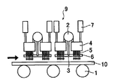
- FIG. 1 is a diagram showing a basic structure of a cooling device for an upper surface of a hot-rolled steel strip according to an embodiment of the present invention.
- This cooling device is on the upper surface of the table roller 1 that conveys the hot-rolled steel strip, and the quick cooling header 4 and the quick cooling nozzle 5 are arranged on both sides with the slow cooling header 2 and the slow cooling nozzle 3 as the center. These are collectively arranged as a single cooling unit 9 between the table rollers 1.
- a protector 6 is installed at the tip of the slow cooling nozzle 3 and the rapid cooling nozzle 5 to protect the nozzle.
- the protector 6 is provided with a plurality of guide holes for passing cooling water, and the slow cooling nozzle 3 and the rapid cooling nozzle 5 are arranged so as to inject cooling water onto the steel strip surface through the guide holes. Has been.
- the cooling unit 9 is provided with an elevating device (elevating unit) 7 and has a structure capable of moving from a position close to the table roller 1 to a distance of 1000 mm or more.
- protector 6 and the cooling unit 9 are connected (a specific structure is not shown), and is configured to move up and down integrally by the lifting unit 7.
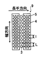
- FIG. 2 shows the arrangement of the nozzles when the cooling unit 9 is viewed from below.
- the slow cooling nozzle 3 and the rapid cooling nozzle 5 are nozzles that can eject rod-shaped cooling water (rod-shaped cooling water nozzles).
- the rod-shaped cooling water refers to cooling water ejected from a circular (including elliptical or polygonal) nozzle outlet.
- the rod-shaped cooling water in the present invention is not a spray-like jet, but a film-like laminar flow, and the cross section of the water flow from the nozzle outlet to the steel strip is maintained in a substantially circular shape. It refers to cooling water with a characteristic water flow.
- the slow cooling nozzle 3 has a relatively large diameter and is arranged side by side in the width direction of the steel strip
- the rapid cooling nozzle 5 has a relatively small diameter and is arranged in a plurality in the width direction and the conveying direction of the steel strip, Form.
- the width direction simply means the width direction of the steel strip
- the transport direction simply means the transport direction of the steel strip.
- the cooling rate of the steel strip is proportional to the amount of cooling water and inversely proportional to the plate thickness.
- the steel strip to be cooled varies, for example, from a material with a minimum thickness of 1.0 to 1.2 mm of a general hot-rolled steel strip to a material with a maximum thickness of 25 to 30 mm, but when cooled with the same amount of cooling water, the cooling rate is 20 It changes about 30 times. Therefore, the thicker the plate thickness, the slower the cooling rate, and it is difficult to utilize a quenched structure such as bainite and martensite. Therefore, there is a potential need to increase the cooling rate. Therefore, as shown in FIG. 3, the relatively thick plate is configured so that the cooling water is supplied to the rapid cooling header 4 in the state where the cooling unit 9 is brought close to the steel strip 10 by the elevating device 7. Inject from 5.
- thin plates can secure a certain cooling rate even with a small amount of cooling water, but there are many cases where the steel plate can pass through.
- the steel strip decelerates due to fluid resistance generated when flying with the lift generated in the steel strip or passing through the cooling water
- problems such as the occurrence of loops. Therefore, as a countermeasure against flying, it is preferable to cool the nozzle with a low pressure and a small amount of water in order to inject the nozzle from a distance from the table roller 1 and to avoid deceleration of the steel strip due to fluid resistance. Therefore, as shown in FIG.
- the slow cooling nozzle 3 and the rapid cooling nozzle 5 have a structure having a length of 5 times or more with respect to each nozzle diameter in order to reduce droplet formation of the jet cooling water.
- the tips of the slow cooling nozzle 3 and the rapid cooling nozzle 5 may be located in the guide hole of the protector 6 or may be located immediately above the guide hole.
- the slow cooling header 2 slow cooling nozzle 3
- the rapid cooling header 4 rapid cooling nozzle 5
- the cooling rate can be switched between cooling and slow cooling.
- the configuration of the rapid cooling nozzle 5 is such that the rapid cooling nozzle 5 injects a large amount of water, so that water tends to accumulate on the steel plate, and a vapor film is generated during the water cooling, which may reduce the cooling capacity. Therefore, it is necessary to dispose a large number of small nozzle diameters and break the vapor film by increasing the nozzle injection flow rate.
- the small diameter nozzle is selected with the aim of increasing the nozzle injection flow rate without increasing the input amount, and in order to ensure temperature uniformity, a plurality of nozzles are arranged in the width direction / conveyance direction to form a group jet.
- the nozzle diameter is preferably 10 mm or less, and in order to ensure temperature uniformity in the width direction, the nozzle diameter is preferably installed at a pitch of 3 to 20 times the nozzle diameter in the width direction.
- the conveyance direction since the steel strip 10 is cooled while being conveyed, the mounting pitch has little influence on the temperature uniformity and may be arranged freely.
- the vapor film can be stably broken in a region of 900 ° C. or lower, which is a general plate temperature of a hot-rolled steel strip or a thick steel plate.
- the smaller the nozzle diameter the more clogging with dust mixed with the cooling water. Becomes higher. Practically, the nozzle diameter is preferably 3.0 mm or more.
- the nozzle outlet flow rate is preferably 45 m / s or less.
- the cooling water sprayed from the nozzle 5 collides with the steel strip 10 and then leaks in the steel strip conveying direction and the width direction.
- the cooling water leaks in the steel strip conveying direction, the steel strip 10 is transported with the leaked water on the steel strip upper surface, so that local supercooling occurs at the portion of the riding water. Therefore, it is preferable to provide a draining means before and after the cooling device.
- draining means purge with high-pressure water or the like is a common method, and this method may be used, but it is preferable to arrange draining rolls 8 before and after the cooling unit 9 as shown in FIG.
- the draining roll 8 forms a solid wall and drains water, so the reliability is high.
- a plurality of cooling units 9 comprising the rapid cooling header 4 and the rapid cooling nozzle 5 / slow cooling header 2 and the slow cooling nozzle 3 are installed. This is because the water can be surely drained in the vicinity of the unit into which the cooling water has been poured.
- the rod-shaped cooling water from the rapid cooling nozzle 5 cannot be injected in the vicinity of the draining roll 8 or the slow cooling nozzle 3 installation portion, so that the cooling capacity tends to be lowered. Therefore, as shown in FIG. 6, when cooling water is injected by inclining the draining roll 8 or the rapid cooling nozzle 5 in the vicinity of the slow cooling nozzle 3, rod-shaped cooling water collides evenly between the draining rolls 8 to obtain a high cooling capacity. be able to.
- the cooling water amount is 3 to 5 with respect to the existing laminar cooling if the flow rate per unit area is designed to be 1000 L / min ⁇ m 2 or more with respect to the area cooled by one cooling unit 9. Double cooling rate can be obtained.
- the cooling water is sprayed from a distant place with a flow rate as small as possible due to the plate-passability of the steel strip 10.
- the nozzle outlet flow rate is set to 0.4 m / s or more from the viewpoint of preventing breakage of the cooling water due to surface tension and 3.0 m / s or less from the viewpoint of preventing jetting, the slow cooling nozzle is started from a distance of about 1000 mm.
- the rod-shaped cooling water injection by No. 3 is not jetted and is not broken, and the cooling water can collide with the steel strip 10 in a continuous flow state. Further, the larger the diameter of the slow cooling nozzle 3, the more difficult it is to break or jet the cooling water. However, in practice, the nozzle diameter is preferably in the range of 10 mm to 30 mm.
- the mounting pitch in the width direction of the slow cooling nozzle 3 is narrower than 1.5 times the diameter of the slow cooling nozzle 3, the cooling water sprayed from the adjacent nozzle due to the nozzle mounting error or the like before reaching the steel strip 10 If it is spaced 20 times or more the nozzle diameter, the temperature uniformity in the width direction cannot be ensured as described above for the rapid cooling nozzle 5.
- the slow cooling nozzle 3 does not form a nozzle group like the rapid cooling nozzle 5, the nozzle pitch should be narrower than that of the rapid cooling nozzle 5. Therefore, more preferably, the mounting pitch of the slow cooling nozzle 3 is 5 times or less with respect to the nozzle diameter.
- the amount of cooling water may be designed so that the flow rate per unit area is 700 to 2000 L / min ⁇ m 2 with respect to the area cooled by one unit, but the nozzle diameter, nozzle pitch, nozzle outlet flow velocity
- the slow cooling nozzles 3 may be arranged in a plurality of rows in the transport direction as shown in FIG.
- it if it is installed more than three rows, it becomes a group jet like the rapid cooling nozzle 5 and the cooling water flow increases. In this state, the fluid resistance increases when a thin object is passed, and the passage becomes unstable. Therefore, it is preferable to install one to three rows of slow cooling nozzles 3 in the transport direction for one cooling unit 9. By doing in this way, the cooling rate substantially equivalent to the existing laminar cooling can be obtained.
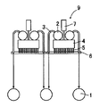
- the slow cooling nozzle 3 can be used to improve the sheet-passability of a thin steel strip by a fluid force, and a schematic diagram illustrating this is shown in FIG.
- the cooling water sprayed from the slow cooling nozzle 3 is dropped between the table rollers, the steel strip 10 is bent by the fluid force.
- the apparatus 11 is installed and the cooling water having the same momentum as the cooling water ejected from the slow cooling nozzle 3 is ejected from the lower surface cooling apparatus 11 so as to balance the fluid force, so that bending does not occur.
- the cooling unit 9 is divided into two in the transport direction, and the slow cooling header 2 and the slow cooling nozzle 3 are arranged in the central space. 10 (a) and 10 (b), the slow cooling header 2 is arranged above the rapid cooling header 4, and the slow cooling nozzle 3 is shaped like a hairpin.
- the rapid cooling nozzles 5 are arranged on the upstream side or the downstream side in the transport direction, or when the slow cooling nozzles 3 are arranged in two rows in the transport direction as described above with reference to FIG.
- the slow cooling nozzle 3 in the form of a hairpin is arranged on the upstream side and the downstream side of the rapid cooling header 4 so that the cooling water falls on the table roller 1.
- the rapid cooling header 4 is divided into two in the transport direction, the slow cooling header 2 and the slow cooling nozzle 3 are arranged in the central space, and cooling water is supplied between the table rollers 1.
- positioned on the lower surface side and having the same fluid force as the slow cooling nozzle 3 is mentioned.
- the lower surface cooling device 11 may be a spray cooling nozzle, a rod-shaped cooling water nozzle, or the like.
- the fluid force on the bottom surface of the steel strip 10 should be balanced with the top surface of the steel strip 10, but if the fluid force on the bottom surface is too high, there is a risk that the steel strip 10 will float, and the fluid force on the bottom surface When the amount is too small, the bending of the slow cooling nozzle 3 due to the cooling water increases, and bounce is likely to occur. In particular, when the steel strip 10 is lifted, the driving force from the table roller 1 is not transmitted, which causes a problem. Therefore, it is preferable to select a lower surface cooling device having a smaller fluid force than the sum of the weight of the steel strip 10 and the fluid force of the slow cooling nozzle 3.
- cooling device for the hot-rolled steel strip has been described in mind, but the cooling device for the thick steel plate may be similarly used.
- Example 1 of the present invention the cooling device of the present invention was applied to a hot-rolled steel strip production line.
- FIG. 13 is an explanatory diagram of a hot-rolled steel strip production line to which the cooling device of the present invention is applied.
- a slab having a thickness of 250 mm is heated to 1200 ° C. by a heating furnace 60 and then predetermined by a rough rolling mill group 61 and a finish rolling mill group 62. After being rolled to a plate thickness, the sheet is cooled by the cooling device 21 of the present invention and the existing cooling device 31 and wound by the coiler 63.
- 65 in FIG. 13 is a radiation thermometer.
- the cooling device 21 of the present invention divides the rapid cooling header 4 into two, and the slow cooling header 2 and the slow cooling nozzle 3 are arranged therebetween.
- the cooling unit 9 is provided, and a draining roll 8 that moves up and down in conjunction with the cooling unit 9 is installed on the upstream side / downstream side of the rapid cooling header 4 in the steel strip conveyance direction.
- the cooling unit 9 including the draining roll 8 on the upper surface is provided with one cooling unit 9 for the three table rollers 1. It is comprised so that.
- the draining roll 8 is arranged so as to be paired with the upstream and downstream table rollers 1 of the cooling device 21, and the slow cooling nozzle 3 is arranged so that the cooling water falls directly on the table roller 1. .
- the rapid cooling nozzle 5 has a diameter of 5 mm, and is attached so as to form a group jet at a pitch of 50 mm in the width direction and a pitch of 70 mm in the transport direction, and the rapid cooling nozzle 5 injects at a flow velocity of 12 m / s.
- the water density of the rapid cooling nozzle 5 in the cooling unit 9 is 4500 L / min ⁇ m 2 .
- the slow cooling nozzle 3 has a diameter of 20 mm, is attached at a pitch of 50 mm in the width direction, and is inserted in one row between the rapid cooling headers 4.
- the slow cooling nozzle 3 has a flow rate of 0.7 m / s. Spray.
- the water density of the slow cooling nozzle 3 in the cooling unit 9 is 730 L / min ⁇ m 2 .
- the cooling unit 9 is arranged so that the distance from the top of the table roller 1 to the tips of the slow cooling nozzle 3 and the rapid cooling nozzle 5 is 1300 mm, and is lowered by the lifting device 7 and can be freely positioned according to the plate thickness. It has a structure that can be stopped with.
- the equipment length of one cooling unit 9 is two pitches (740 mm) of the table roller 1, and 30 cooling units 9 are arranged (the total equipment length is 22). .2m).
- a spray nozzle 11 is attached to the lower surface of the cooling unit 9 so that the amount of water can be changed by changing the spray spray pressure.
- the existing cooling device 31 comprised from a pipe laminar nozzle / spray nozzle is installed in the downstream of the cooling device 21 of this invention.
- the cooling unit 9 of the cooling device 21 of the present invention and the pipe laminator nozzle / spray nozzle of the existing cooling device 31 can be individually turned on and off, and the computer can be appropriately adjusted. Calculate the number of cooling units and the plate passing speed to reach the correct temperature, and determine the cooling unit to turn on water injection.
- Example 1 Invention Example 1, in the hot rolled steel strip production line as described above, a case where a steel strip having a relatively thin plate thickness of 1.6 mm is cooled will be described as Example 1 of the present invention.
- the steel strip tip After rolling to a sheet thickness of 32 mm by the rough rolling mill group 61 and rolling to a sheet thickness of 1.6 mm by the finish rolling mill group 62, the steel strip tip is passed through the cooling device 21 of the present invention at a steel strip tip speed of 700 mpm. The steel strip is accelerated at 10 mpm / s while being wound around the coiler 63.
- the cooling device 21 of the present invention retracts from the table roller 1 to a position of 1300 mm, injects cooling water from the slow cooling nozzle 3, and cools to 640 ° C.
- the cooling device 11 on the lower surface had a water density of 500 L / min ⁇ m 2 and a spray injection flow rate of 3 m / s.
- Example 1 of the present invention the steel strip does not bounce into the plate, and the entire length is cooled in a range of ⁇ 20 ° C. with respect to the target winding temperature of 640 ° C. Was made. Moreover, the cooling rate when the steel strip center portion at this time passed from 750 ° C. to 650 ° C. was 140 ° C./s.
- Example 2 of the present invention a case where a steel strip having a thickness of 5.0 mm and a relatively large thickness is cooled will be described.
- the steel strip tip After rolling to a sheet thickness of 40 mm by the rough rolling mill group 61 and rolling to a sheet thickness of 5.0 mm by the finish rolling mill group 62, the steel strip tip is passed between the cooling devices 21 of the present invention at a steel strip tip speed of 500 mpm. The steel strip is accelerated at 2 mpm / s while being wound around the coiler 63.
- the cooling device 21 of the present invention adjusts the distance from the table roller 1 to the tip of the rapid cooling nozzle 5 to be 30 mm (that is, the distance from the tip of the nozzle to the steel strip is 25 mm). Cooling water is poured from the nozzle 5 to cool to 500 ° C.
- the cooling device 11 on the lower surface has a water density of 4500 L / min ⁇ m 2 and a spray injection flow rate of 12 m / s.
- Example 2 of the present invention it was possible to cool the entire length in a range of ⁇ 25 ° C. with respect to the target winding temperature of 500 ° C. Moreover, the cooling rate when the steel strip center part at this time passes 750 degreeC to 650 degreeC became 200 degreeC / s. When the steel strip at this time was investigated, the structure of the steel strip was entirely composed of bainite and had high strength and toughness.
- the steel strip used in Example 2 of the present invention is a component system that can be made into a full-bainite structure by setting the cooling rate to 70 ° C./s or more, and the rapid cooling nozzle 5 of the cooling device 21 of the present invention. Without using, the intended mechanical properties cannot be obtained.
- Example 3 As Example 3 of the present invention, a case where a steel strip having a plate thickness of 25.0 mm and a thick plate is cooled will be described.
- the steel strip After rolling to a sheet thickness of 80 mm by the rough rolling mill group 61 and rolling to a sheet thickness of 25.0 mm by the finish rolling mill group 62, the steel strip is passed through the cooling device 21 of the present invention at a speed of 150 mpm and kept at a constant speed. Wind up with a coiler 63.
- the cooling device 21 of the present invention adjusts the distance from the table roller 1 to the tip of the rapid cooling nozzle 5 to be 275 mm (that is, the distance from the nozzle tip to the steel strip is 250 mm), and performs rapid cooling. Cooling water is poured from the nozzle 5 to cool to 450 ° C.
- the cooling device 11 on the lower surface had a water density of 8000 L / min ⁇ m 2 and a spray injection flow rate of 17 m / s.
- Example 3 of the present invention it was possible to cool the entire length in a range of ⁇ 15 ° C. with respect to the target winding temperature of 450 ° C. Moreover, the cooling rate when the steel strip center part at this time passes 750 degreeC to 650 degreeC became 40 degreeC / s.
- the structure of the steel plate was entirely composed of bainite and had high strength and toughness.
- the steel strip used in Example 3 of the present invention is a component system that can be made into a full-bainite structure by setting the cooling rate to 25 ° C./s or more, and the rapid cooling nozzle 5 of the cooling device 21 of the present invention. Without using, the intended mechanical properties cannot be obtained.
- Example 2 of the present invention the cooling device of the present invention was applied to a thick steel plate production line.
- FIG. 16 is an explanatory diagram of a thick steel plate production line to which the cooling device of the present invention is applied.
- a slab having a thickness of 250 mm is heated to 1200 ° C. by a heating furnace 70, and then up to a predetermined plate thickness by a rough rolling mill 71 and a finish rolling mill 72. After being reverse-rolled, it is cooled by the cooling device 21 of the present invention, corrected by the roller leveler 73 and then shipped.
- 65 in FIG. 16 is a radiation thermometer.
- Thick steel plates are generally thicker than hot-rolled steel strips, so it is unlikely to cause plate-through problems.
- the plate thickness varies from 6 to 100 mm and the cooling rate has been high in the past. Since the alloy element is added so that the slower the plate thickness is, the easier it is to form bainite, the higher the plate thickness, the higher the alloy cost. Therefore, it is advantageous in terms of cost to manufacture the same component system so that the cooling rate for each plate thickness does not change as much as possible.
- it demonstrates using the steel type which stabilizes the structure
- the cooling device 21 of the present invention divides the rapid cooling header 4 into two and arranges the slow cooling header 2 and the slow cooling nozzle 3 therebetween.
- the cooling unit 9 is provided. Further, since the mounting pitch of the table roller 1 is 1000 mm and the diameter is 450 mm, the cooling unit 9 is mounted above the table rollers, and the slow cooling nozzle 3 is arranged so that the cooling water falls between the table rollers. It is as.
- the rapid cooling nozzle 5 has a diameter of 5 mm, and is attached so as to form a group jet at a pitch of 50 mm in the width direction and a pitch of 70 mm in the transport direction, and the rapid cooling nozzle 5 injects at a flow rate of 7 m / s.
- the water density of the rapid cooling nozzle 5 in the cooling unit 9 is 3300 L / min ⁇ m 2 .
- the slow cooling nozzle 3 has a diameter of 20 mm, is attached at a pitch of 70 mm in the width direction, and is inserted in one row between the rapid cooling headers 4. From the slow cooling nozzle 3, the flow rate is 3.0 m / s. Spray. In this case, the water density of the slow cooling nozzle 3 in the cooling unit 9 is 1600 L / min ⁇ m 2 .
- the cooling unit 9 is arranged such that the distance from the top of the table roller 1 to the tip of the slow cooling nozzle 3 and the rapid cooling nozzle 5 is 1000 mm.
- the cooling unit 9 is lowered by the elevating device 7 and can be freely positioned according to the plate thickness. It has a structure that can be stopped with.
- the equipment length of one cooling unit 9 is one table roller 1 (1000 mm), and 15 cooling units 9 are arranged (the total equipment length is 15 m). ).
- Three rows of spray nozzles 11 are attached to the lower surface of the cooling unit 9 in the direction of travel of the steel plate, and the amount of water can be changed by turning on / off individual water injection and changing the spray injection pressure.
- the slow cooling nozzle 3 and the spray nozzle in the second row in the steel plate traveling direction on the lower surface have a structure in which cooling water collides at the same position.
- purge units 74 and 75 capable of injecting high-pressure water are installed as draining devices on the upstream side and the downstream side of the cooling unit 21 of the present invention.
- the cooling unit 9 of the cooling device 21 of the present invention can be individually turned on and off, and the number of cooling units and the plate passing speed at which an appropriate temperature is obtained are calculated by a computer. Then, the cooling unit or the like to turn on water injection is determined.
- Example 4 Invention Example 4, in the thick steel plate production line as described above, a case where a thick steel plate having a thickness of 10 mm is cooled will be described as Example 4 of the present invention.
- the cooling device 21 of the present invention After rolling to a plate thickness of 30 mm by the rough rolling mill 71 and rolling to a plate thickness of 10 mm by the finish rolling mill 72, the cooling device 21 of the present invention cools the sheet while passing it at a steel plate speed of 150 mpm.
- the cooling device 21 of the present invention retreats to a position of 1300 mm from the table roller 1 and cools water to 500 ° C. by pouring cooling water from the slow cooling nozzle 3.
- the cooling device 11 on the lower surface has a water density of 2000 L / min ⁇ m 2 and a spray injection flow rate of 10 m / s in the spray nozzle group in the second row from the upstream side in the three rows in the transport direction.
- Example 4 of the present invention it was possible to cool the entire length in the range of ⁇ 25 ° C. with respect to 500 ° C. which is the target cooling end temperature. Moreover, the cooling rate when the steel plate center part at this time passes 750 degreeC to 650 degreeC became 45 degreeC / s.
- Example 5 As Example 5 of the present invention, a case where a thick steel plate having a thickness of 25 mm is cooled will be described. After rolling to a plate thickness of 50 mm by the rough rolling mill 71 and rolling to a plate thickness of 25 mm by the finish rolling mill 72, the cooling device 21 of the present invention cools the plate while passing it at a steel plate speed of 80 mpm.
- the cooling device 21 of the present invention adjusts the distance from the table roller 1 to the tip of the rapid cooling nozzle 5 to be 200 mm (that is, the distance from the tip of the nozzle to the steel plate is 175 mm). Cooling water is poured from 5 and cooled to 500 ° C. In addition, the cooling device 11 on the lower surface had a water density of 6000 L / min ⁇ m 2 and a spray injection flow rate of 12 m / s.
- Example 5 of the present invention the entire length could be cooled in a range of ⁇ 25 ° C. with respect to the target winding temperature of 500 ° C. Moreover, the cooling rate when the steel plate center part at this time passes 750 degreeC to 650 degreeC became 45 degreeC / s. When the steel plate at this time was investigated, the structure of the steel plate was entirely composed of bainite and had high strength and toughness.
- the slow cooling nozzle 3 is used for a relatively thin plate like the cooling device of the present invention, It can be seen that it is effective to use the rapid cooling nozzle 5 properly for a thick plate.
- Cooling unit of the present invention (combination of slow cooling nozzle and rapid cooling nozzle) DESCRIPTION OF SYMBOLS 31
- Existing cooling device 60 Heating furnace 61 Coarse rolling mill group 62 Finish rolling mill group 63 Coiler 65 Radiation thermometer 70 Heating furnace 71 Coarse rolling mill 72 Finishing rolling mill 73 Roller leveler 74 High pressure water purge on the upstream side of the cooling apparatus 75 Cooling apparatus Downstream high-pressure water purge
Landscapes
- Engineering & Computer Science (AREA)
- Mechanical Engineering (AREA)
- Heat Treatment Of Strip Materials And Filament Materials (AREA)
- Metal Rolling (AREA)
Abstract
Description

緩冷却用の棒状冷却水ノズルを備えるヘッダと、急冷却用の棒状冷却水ノズルを備えるヘッダを一つの冷却ユニットとして構成し、該冷却ユニットは一体となって上下に昇降することが可能な昇降ユニットを具備することを特徴とする熱延鋼板の冷却装置。
例えば、熱延鋼帯の仕上圧延後の冷却に適用した場合、板厚が2.0mmを下回り通板性に問題がある素材も、板厚が厚い素材も、冷却速度をあまり変えることなく安定して冷却ができるようになった。
すなわち、本発明の冷却装置は、冷却を安定しつつ、冷却水量が広い範囲で変更できるようになっているため、板厚が2.0mmを下回る薄い鋼帯で問題となる通板性も、緩冷却ノズルを適用することにより、安定通板が可能となり、さらに板厚が5mmを超える領域の鋼帯では、従来の設備の数倍の高い冷却速度を得ることができるので、少ない合金添加で高強度・高靭性を有する鋼板の製造が可能となった。
また、厚鋼板の冷却に適用した場合、板厚が異なっても冷却速度が変化しにくくできるため、同一成分系の鋼種で同一特性を出すことができ、従来強度や靭性などを特別な元素を付加することなく製造することが可能となった。
さらに、緩冷却用のヘッダと急冷却用のヘッダを一つの冷却ユニットとして一体化することにより、狭いスペースで冷却装置の設置が可能になった。この結果、特に現有の圧延設備における少ない空きスペースへの導入が可能となり、高機能商品の製造が可能となった。
前記のような熱延鋼帯製造ラインにおいて、本発明例1として、比較的板厚の薄い板厚1.6mmの鋼帯を冷却する場合について説明する。
本発明例2として、板厚5.0mmと比較的板厚の厚い鋼帯を冷却する場合について説明する。
本発明例3として、板厚25.0mmと板厚の厚い鋼帯を冷却する場合について説明する。
前記のような厚鋼板製造ラインにおいて、本発明例4として、板厚10mmの厚鋼板を冷却する場合について説明する。
本発明例5として、板厚25mmの厚鋼板を冷却する場合について説明する。
粗圧延機71により板厚50mmまで圧延し、仕上圧延機72により板厚25mmまで圧延した後、本発明の冷却装置21により、鋼板速度80mpmで通板させながら冷却する。
すなわち、この成分系では、本発明の冷却装置21の急冷却ノズル5を使用しなければ、目的とした機械特性を得ることが出来ない。
2 緩冷却ヘッダ
3 緩冷却ノズル(緩冷却用棒状冷却水ノズル)
4 急冷却ヘッダ
5 急冷却ノズル(急冷却用棒状冷却水ノズル)
6 プロテクター
7 昇降装置(昇降ユニット)
8 水切りロール
9 冷却ユニット
10 熱延鋼帯
11 下面冷却ノズル
12 厚鋼板
21 本発明の冷却ユニット(緩冷却ノズルと急冷却ノズルの組合せ)
31 既存の冷却装置
60 加熱炉
61 粗圧延機群
62 仕上圧延機群
63 コイラー
65 放射温度計
70 加熱炉
71 粗圧延機
72 仕上圧延機
73 ローラーレベラー
74 冷却装置上流側の高圧水パージ
75 冷却装置下流側の高圧水パージ
Claims (14)
- 熱延鋼板を冷却するための冷却装置において、
緩冷却用の棒状冷却水ノズルを備えるヘッダと、急冷却用の棒状冷却水ノズルを備えるヘッダを一つの冷却ユニットとして構成し、該冷却ユニットは一体となって上下に昇降することが可能な昇降ユニットを具備することを特徴とする熱延鋼板の冷却装置。 - 前記冷却ユニットは、前記緩冷却用の棒状冷却水ノズルに対して、熱延鋼板の搬送方向の上流側および/または下流側に急冷却用の棒状冷却水ノズルが配置されることを特徴とする請求項1に記載の熱延鋼板の冷却装置。
- 前記昇降ユニットの昇降機能により、前記緩冷却用の棒状冷却水ノズルを使用する場合は、熱延鋼板から当該ノズルの先端までの距離が1000mm以上になるように前記冷却ユニットを設定し、急冷却用の棒状冷却水ノズルを使用する場合は、熱延鋼板から当該ノズルの先端までの距離が当該ノズルの口径の5~50倍の範囲になるように前記冷却ユニットを設定することを特徴とする請求項1または2に記載の熱延鋼板の冷却装置。
- 前記冷却ユニットの熱延鋼板の搬送方向の前後には、水切り装置を有することを特徴とする請求項1~3のいずれかに記載の熱延鋼板の冷却装置。
- 前記水切り装置が水切りロールであることを特徴とする請求項4に記載の熱延鋼板の冷却装置。
- 前記緩冷却用の棒状冷却水ノズルは、熱延鋼板を搬送するテーブルローラーの上方に配置されていることを特徴とする請求項1~5のいずれかに記載の熱延鋼板の冷却装置。
- 前記緩冷却用の棒状冷却水ノズルは、熱延鋼板を搬送するテーブルローラー間に設置された下面冷却ノズルの噴射位置の上方に配置されていることを特徴とする請求項1~5のいずれかに記載の熱延鋼板の冷却装置。
- 前記冷却ユニットに、前記緩冷却用の棒状冷却水ノズルと急冷却用の棒状冷却水ノズルとを保護するための平面状のプロテクターを転結し、該プロテクターは冷却水通過用のガイド孔を有し、そのガイド孔を介して、前記緩冷却用の棒状冷却水ノズルおよび急冷却用の棒状冷却水ノズルから冷却水が噴射されることを特徴とする請求項1~7のいずれかに記載の熱延鋼板の冷却装置。
- 前記緩冷却用の棒状冷却水ノズルは、ノズル口径が10mm以上、ノズル出口流速が3m/s以下であることを特徴とする請求項1~8のいずれかに記載の熱延鋼板の冷却装置。
- 前記急冷却用の棒状冷却水ノズルは、ノズル口径が10mm以下、ノズル出口流速が7m/s以上であることを特徴とする請求項1~9のいずれかに記載の熱延鋼板の冷却装置。
- 前記緩冷却用の棒状冷却水ノズルは、冷却する熱延鋼板の幅方向にノズル口径の1.5倍から5倍の間隔で複数並べられ、これを1列の冷却ノズル列とした場合に、一個のヘッダ内で1~3列の冷却ノズル列が配置されていることを特徴とする請求項1~10のいずれかに記載の熱延鋼板の冷却装置。
- 前記急冷却用の棒状冷却水ノズルは、冷却する熱延鋼板の幅方向にノズル口径の3倍から20倍の間隔で複数並べて配置されていることを特徴とする請求項1~11のいずれかに記載の熱延鋼板の冷却装置。
- 前記熱延鋼板が1~30mmの板厚を有する熱延鋼帯である請求項1に記載の熱延鋼板の冷却装置。
- 前記熱延鋼板が6~100mmの板厚を有する厚鋼板である請求項1に記載の熱延鋼板の冷却装置。
Priority Applications (4)
| Application Number | Priority Date | Filing Date | Title |
|---|---|---|---|
| US13/260,870 US8931321B2 (en) | 2009-03-30 | 2010-03-25 | Hot rolled steel sheet cooling apparatus |
| EP10758854.3A EP2415536B1 (en) | 2009-03-30 | 2010-03-25 | Cooling device for hot rolled steel sheet |
| KR1020117025040A KR101162070B1 (ko) | 2009-03-30 | 2010-03-25 | 열연 강판의 냉각 장치 |
| CN2010800148507A CN102378655B (zh) | 2009-03-30 | 2010-03-25 | 热轧钢板的冷却装置 |
Applications Claiming Priority (4)
| Application Number | Priority Date | Filing Date | Title |
|---|---|---|---|
| JP2009-081608 | 2009-03-30 | ||
| JP2009081608 | 2009-03-30 | ||
| JP2010008683 | 2010-01-19 | ||
| JP2010-008683 | 2010-01-19 |
Publications (1)
| Publication Number | Publication Date |
|---|---|
| WO2010114083A1 true WO2010114083A1 (ja) | 2010-10-07 |
Family
ID=42828371
Family Applications (1)
| Application Number | Title | Priority Date | Filing Date |
|---|---|---|---|
| PCT/JP2010/055991 Ceased WO2010114083A1 (ja) | 2009-03-30 | 2010-03-25 | 熱延鋼板の冷却装置 |
Country Status (7)
| Country | Link |
|---|---|
| US (1) | US8931321B2 (ja) |
| EP (1) | EP2415536B1 (ja) |
| JP (1) | JP4678069B1 (ja) |
| KR (1) | KR101162070B1 (ja) |
| CN (1) | CN102378655B (ja) |
| TW (1) | TWI460031B (ja) |
| WO (1) | WO2010114083A1 (ja) |
Cited By (5)
| Publication number | Priority date | Publication date | Assignee | Title |
|---|---|---|---|---|
| CN105132855A (zh) * | 2015-09-29 | 2015-12-09 | 武汉赛恩冶金技术开发有限公司 | 一种热轧螺纹钢轧后穿水控冷工艺生产在线表面防锈的新工艺 |
| CN105200205A (zh) * | 2015-10-16 | 2015-12-30 | 内蒙古包钢钢联股份有限公司 | 一种双相钢快冷装置及双相钢快冷后温度控制方法 |
| KR20180031738A (ko) | 2015-08-31 | 2018-03-28 | 신닛테츠스미킨 카부시키카이샤 | 강판 |
| CN113172101A (zh) * | 2021-04-29 | 2021-07-27 | 泉州市润协产品设计有限公司 | 一种低温韧性结构钢板制造用的快速冷却装置 |
| WO2023042545A1 (ja) * | 2021-09-16 | 2023-03-23 | Jfeスチール株式会社 | 厚鋼板の製造方法および製造設備 |
Families Citing this family (29)
| Publication number | Priority date | Publication date | Assignee | Title |
|---|---|---|---|---|
| JP5940941B2 (ja) * | 2012-08-31 | 2016-06-29 | Primetals Technologies Japan株式会社 | 熱延鋼板の製造設備 |
| JP6006049B2 (ja) * | 2012-08-31 | 2016-10-12 | Primetals Technologies Japan株式会社 | 熱延鋼板の製造装置 |
| CN102912097B (zh) * | 2012-10-09 | 2013-12-11 | 范华平 | 一种轧钢淬火用环式穿水冷却设备 |
| DE102012223848A1 (de) * | 2012-12-19 | 2014-06-26 | Sms Siemag Ag | Vorrichtung und Verfahren zum Kühlen von Walzgut |
| EP2792428A1 (de) | 2013-04-15 | 2014-10-22 | Siemens VAI Metals Technologies GmbH | Kühleinrichtung mit breitenabhängiger Kühlwirkung |
| DE102013019698A1 (de) * | 2013-05-03 | 2014-11-06 | Sms Siemag Ag | Verfahren zur Herstellung eines metallischen Bandes |
| CN103357676B (zh) * | 2013-07-03 | 2015-09-30 | 首钢总公司 | 一种分段控制平整液喷射压力的系统及其方法 |
| KR101486976B1 (ko) * | 2013-10-24 | 2015-01-27 | 주식회사 포스코 | 압연소재의 디스케일 장치 |
| DE102014001146A1 (de) * | 2014-01-31 | 2015-08-06 | Loi Thermprocess Gmbh | Einrichtung zum Abkühlen von platten- oder bahnförmigem Blech aus Metall und Verfahren zur Wärmebehandlung |
| EP2982453A1 (de) * | 2014-08-06 | 2016-02-10 | Primetals Technologies Austria GmbH | Einstellen eines gezielten Temperaturprofiles an Bandkopf und Bandfuß vor dem Querteilen eines Metallbands |
| JP6245766B2 (ja) * | 2015-05-26 | 2017-12-13 | Primetals Technologies Japan株式会社 | 熱延鋼板の冷却装置及びそのマスク部材位置調整方法 |
| KR101616355B1 (ko) | 2015-06-17 | 2016-04-28 | 주식회사 포스코 | 소재 냉각 장치 및 방법 |
| CN105087878A (zh) * | 2015-09-18 | 2015-11-25 | 冯英育 | 真空热处理方法 |
| JP6233613B2 (ja) * | 2016-01-26 | 2017-11-22 | Jfeスチール株式会社 | 熱延鋼帯の製造設備列および熱延鋼帯の製造方法 |
| JP6233614B2 (ja) * | 2016-01-27 | 2017-11-22 | Jfeスチール株式会社 | 熱延鋼帯の製造設備列および熱延鋼帯の製造方法 |
| EP3251764B1 (de) | 2016-05-31 | 2019-07-03 | Primetals Technologies Austria GmbH | Verfahren und vorrichtung zur stabilisierung einer bewegung eines gewalzten metallischen bandes auf einem rollgang |
| JP6447836B2 (ja) * | 2016-06-30 | 2019-01-09 | Jfeスチール株式会社 | 熱延鋼帯の製造方法および熱延鋼帯の製造設備 |
| CN105921535B (zh) * | 2016-07-12 | 2017-09-15 | 北京科技大学 | 一种板带钢控制冷却超密集冷却器 |
| CA2947367A1 (en) * | 2016-11-03 | 2018-05-03 | Shawcor Ltd. | Apparatus and method for cooling coated pipe |
| RU2745923C1 (ru) * | 2017-10-31 | 2021-04-02 | ДжФЕ СТИЛ КОРПОРЕЙШН | Установка и способ для производства толстого стального листа |
| DE102017127470A1 (de) | 2017-11-21 | 2019-05-23 | Sms Group Gmbh | Kühlbalken und Kühlprozess mit variabler Abkühlrate für Stahlbleche |
| JP6569843B1 (ja) | 2017-12-20 | 2019-09-04 | Jfeスチール株式会社 | 厚鋼板の冷却装置および冷却方法ならびに厚鋼板の製造設備および製造方法 |
| KR102010088B1 (ko) * | 2017-12-26 | 2019-08-12 | 주식회사 포스코 | 충돌방지장치 |
| JP7017439B2 (ja) * | 2018-03-07 | 2022-02-08 | 株式会社神戸製鋼所 | 厚鋼板冷却方法 |
| DE102018109579A1 (de) * | 2018-04-20 | 2019-10-24 | Schwartz Gmbh | Temperiervorrichtung zur partiellen Kühlung eines Bauteils |
| WO2021033723A1 (ja) * | 2019-08-21 | 2021-02-25 | Jfeスチール株式会社 | 厚鋼板の製造設備及び製造方法 |
| CN110899347B (zh) * | 2019-11-22 | 2021-05-07 | 常州新武轨道交通新材料有限公司 | 一种热轧钢板的冷却装置 |
| CN111850258A (zh) * | 2020-06-20 | 2020-10-30 | 东风汽车底盘系统有限公司 | 一种导向臂淬火冷却系统 |
| CN117327877B (zh) * | 2023-09-27 | 2026-03-06 | 武汉钢铁有限公司 | 一种淬火生产线及钢板淬火板形控制方法 |
Citations (10)
| Publication number | Priority date | Publication date | Assignee | Title |
|---|---|---|---|---|
| JPS617015A (ja) * | 1984-06-22 | 1986-01-13 | Mitsubishi Heavy Ind Ltd | ストリツプ冷却装置 |
| JPS62260022A (ja) | 1986-05-01 | 1987-11-12 | Ishikawajima Harima Heavy Ind Co Ltd | 鋼板の冷却装置 |
| JPH0570709U (ja) * | 1992-02-28 | 1993-09-24 | 住友金属工業株式会社 | 熱間鋼板の冷却装置 |
| JPH10263669A (ja) | 1997-03-25 | 1998-10-06 | Sumitomo Metal Ind Ltd | 鋼材の冷却方法 |
| JP2002239623A (ja) | 2001-02-15 | 2002-08-27 | Nkk Corp | 熱延鋼帯の冷却装置 |
| JP2004066308A (ja) * | 2002-08-08 | 2004-03-04 | Jfe Steel Kk | 熱延鋼帯の冷却装置および熱延鋼帯の製造方法ならびに熱延鋼帯製造ライン |
| JP2008073766A (ja) * | 2006-08-21 | 2008-04-03 | Jfe Steel Kk | 熱延鋼帯の冷却装置および冷却方法 |
| JP2008073765A (ja) * | 2006-08-21 | 2008-04-03 | Jfe Steel Kk | 熱延鋼帯の冷却装置および冷却方法 |
| JP2008168316A (ja) * | 2007-01-11 | 2008-07-24 | Jfe Steel Kk | 鋼材の冷却装置および冷却方法 |
| JP2008212943A (ja) * | 2007-02-28 | 2008-09-18 | Jfe Steel Kk | 鋼材の冷却装置および冷却方法 |
Family Cites Families (13)
| Publication number | Priority date | Publication date | Assignee | Title |
|---|---|---|---|---|
| JPS57709U (ja) | 1980-05-30 | 1982-01-05 | ||
| JPS58197226A (ja) | 1982-05-13 | 1983-11-16 | Mitsubishi Heavy Ind Ltd | 鋼板冷却装置 |
| US5212975A (en) * | 1991-05-13 | 1993-05-25 | International Rolling Mill Consultants, Inc. | Method and apparatus for cooling rolling mill rolls and flat rolled products |
| JPH0570709A (ja) | 1991-09-11 | 1993-03-23 | Hitachi Chem Co Ltd | 塩素化インジウムフタロシアニン、その製造法およびそれを用いた電子写真感光体 |
| JPH08132122A (ja) | 1994-11-11 | 1996-05-28 | Kawasaki Steel Corp | 熱延ラインの水切り装置 |
| JPH11181529A (ja) | 1997-12-18 | 1999-07-06 | Nippon Steel Corp | 連続焼鈍炉の最終冷却帯における鋼板冷却方法及び装置 |
| JP3562423B2 (ja) | 2000-03-01 | 2004-09-08 | Jfeスチール株式会社 | 熱延鋼帯の冷却装置と、その冷却方法 |
| WO2001064362A1 (en) | 2000-03-01 | 2001-09-07 | Nkk Corporation | Device and method for cooling hot rolled steel band and method of manufacturing the hot rolled steel band |
| JP3642024B2 (ja) | 2000-12-15 | 2005-04-27 | Jfeスチール株式会社 | 熱延鋼帯の熱間圧延設備および圧延方法 |
| EP1889671B1 (en) | 2002-08-08 | 2010-03-10 | JFE Steel Corporation | Cooling apparatus for hot rolled steel strip, manufacturing method for hot rolled steel strip, and production line for hot rolled steel strip |
| KR100642656B1 (ko) * | 2002-08-08 | 2006-11-03 | 제이에프이 스틸 가부시키가이샤 | 열연강대의 냉각장치, 열연강대의 제조방법 및 열연강대의제조라인 |
| JP4355280B2 (ja) * | 2004-11-22 | 2009-10-28 | 新日本製鐵株式会社 | 冷間圧延における潤滑油供給方法 |
| BRPI0621377B1 (pt) * | 2006-03-03 | 2019-07-02 | Jfe Steel Corporation | Dispositivo de resfriamento de tira quente e método de resfriamento |
-
2010
- 2010-03-24 JP JP2010067147A patent/JP4678069B1/ja active Active
- 2010-03-25 CN CN2010800148507A patent/CN102378655B/zh active Active
- 2010-03-25 KR KR1020117025040A patent/KR101162070B1/ko active Active
- 2010-03-25 EP EP10758854.3A patent/EP2415536B1/en active Active
- 2010-03-25 US US13/260,870 patent/US8931321B2/en active Active
- 2010-03-25 WO PCT/JP2010/055991 patent/WO2010114083A1/ja not_active Ceased
- 2010-03-30 TW TW099109541A patent/TWI460031B/zh active
Patent Citations (10)
| Publication number | Priority date | Publication date | Assignee | Title |
|---|---|---|---|---|
| JPS617015A (ja) * | 1984-06-22 | 1986-01-13 | Mitsubishi Heavy Ind Ltd | ストリツプ冷却装置 |
| JPS62260022A (ja) | 1986-05-01 | 1987-11-12 | Ishikawajima Harima Heavy Ind Co Ltd | 鋼板の冷却装置 |
| JPH0570709U (ja) * | 1992-02-28 | 1993-09-24 | 住友金属工業株式会社 | 熱間鋼板の冷却装置 |
| JPH10263669A (ja) | 1997-03-25 | 1998-10-06 | Sumitomo Metal Ind Ltd | 鋼材の冷却方法 |
| JP2002239623A (ja) | 2001-02-15 | 2002-08-27 | Nkk Corp | 熱延鋼帯の冷却装置 |
| JP2004066308A (ja) * | 2002-08-08 | 2004-03-04 | Jfe Steel Kk | 熱延鋼帯の冷却装置および熱延鋼帯の製造方法ならびに熱延鋼帯製造ライン |
| JP2008073766A (ja) * | 2006-08-21 | 2008-04-03 | Jfe Steel Kk | 熱延鋼帯の冷却装置および冷却方法 |
| JP2008073765A (ja) * | 2006-08-21 | 2008-04-03 | Jfe Steel Kk | 熱延鋼帯の冷却装置および冷却方法 |
| JP2008168316A (ja) * | 2007-01-11 | 2008-07-24 | Jfe Steel Kk | 鋼材の冷却装置および冷却方法 |
| JP2008212943A (ja) * | 2007-02-28 | 2008-09-18 | Jfe Steel Kk | 鋼材の冷却装置および冷却方法 |
Non-Patent Citations (1)
| Title |
|---|
| See also references of EP2415536A4 * |
Cited By (9)
| Publication number | Priority date | Publication date | Assignee | Title |
|---|---|---|---|---|
| KR20180031738A (ko) | 2015-08-31 | 2018-03-28 | 신닛테츠스미킨 카부시키카이샤 | 강판 |
| US11519061B2 (en) | 2015-08-31 | 2022-12-06 | Nippon Steel Corporation | Steel sheet |
| CN105132855A (zh) * | 2015-09-29 | 2015-12-09 | 武汉赛恩冶金技术开发有限公司 | 一种热轧螺纹钢轧后穿水控冷工艺生产在线表面防锈的新工艺 |
| CN105200205A (zh) * | 2015-10-16 | 2015-12-30 | 内蒙古包钢钢联股份有限公司 | 一种双相钢快冷装置及双相钢快冷后温度控制方法 |
| CN105200205B (zh) * | 2015-10-16 | 2017-08-25 | 内蒙古包钢钢联股份有限公司 | 一种双相钢快冷装置及双相钢快冷后温度控制方法 |
| CN113172101A (zh) * | 2021-04-29 | 2021-07-27 | 泉州市润协产品设计有限公司 | 一种低温韧性结构钢板制造用的快速冷却装置 |
| WO2023042545A1 (ja) * | 2021-09-16 | 2023-03-23 | Jfeスチール株式会社 | 厚鋼板の製造方法および製造設備 |
| JPWO2023042545A1 (ja) * | 2021-09-16 | 2023-03-23 | ||
| JP7452696B2 (ja) | 2021-09-16 | 2024-03-19 | Jfeスチール株式会社 | 厚鋼板の製造方法および製造設備 |
Also Published As
| Publication number | Publication date |
|---|---|
| EP2415536B1 (en) | 2015-03-11 |
| US20120103052A1 (en) | 2012-05-03 |
| JP2011167759A (ja) | 2011-09-01 |
| KR101162070B1 (ko) | 2012-07-04 |
| KR20110132614A (ko) | 2011-12-08 |
| CN102378655B (zh) | 2013-06-05 |
| EP2415536A4 (en) | 2013-05-01 |
| EP2415536A1 (en) | 2012-02-08 |
| JP4678069B1 (ja) | 2011-04-27 |
| TW201039936A (en) | 2010-11-16 |
| US8931321B2 (en) | 2015-01-13 |
| TWI460031B (zh) | 2014-11-11 |
| CN102378655A (zh) | 2012-03-14 |
Similar Documents
| Publication | Publication Date | Title |
|---|---|---|
| JP4678069B1 (ja) | 熱延鋼板の冷却装置 | |
| JP4449991B2 (ja) | 熱延鋼帯の冷却装置及び方法 | |
| KR101026972B1 (ko) | 열연강대의 냉각 방법 | |
| JP5573837B2 (ja) | 熱延鋼板の冷却装置、冷却方法、製造装置、及び、製造方法 | |
| JP5825250B2 (ja) | 熱延鋼帯の冷却方法および冷却装置 | |
| KR100973691B1 (ko) | 강판의 냉각 설비 및 냉각 방법과, 이를 이용하는 강판의 열간 압연 설비 및 열간 압연 방법 | |
| KR100973692B1 (ko) | 강판의 열간압연 설비 및 열간압연 방법 | |
| JP4924538B2 (ja) | 熱延鋼板の製造装置及び製造方法 | |
| EP2979769A1 (en) | Thick steel plate manufacturing method and manufacturing device | |
| WO2007037095A1 (ja) | 鋼板の冷却設備および製造方法 | |
| JP4518117B2 (ja) | 熱延鋼帯の冷却装置および冷却方法 | |
| JP5613997B2 (ja) | 熱延鋼板の冷却装置、熱延鋼板の製造装置及び製造方法 | |
| JP5428452B2 (ja) | 熱延鋼帯の下面冷却方法および下面冷却装置 | |
| JP5663848B2 (ja) | 熱延鋼板の冷却装置及びその動作制御方法 | |
| JP5515440B2 (ja) | 厚鋼板の冷却設備およびその冷却方法 | |
| JP5556087B2 (ja) | 熱延鋼板の冷却設備および冷却方法 | |
| JP4518116B2 (ja) | 熱延鋼帯の冷却装置および冷却方法 | |
| JP4720198B2 (ja) | 厚鋼板の冷却装置および冷却方法 | |
| JP4962349B2 (ja) | 熱延鋼帯の下面冷却方法および下面冷却装置 |
Legal Events
| Date | Code | Title | Description |
|---|---|---|---|
| WWE | Wipo information: entry into national phase |
Ref document number: 201080014850.7 Country of ref document: CN |
|
| 121 | Ep: the epo has been informed by wipo that ep was designated in this application |
Ref document number: 10758854 Country of ref document: EP Kind code of ref document: A1 |
|
| WWE | Wipo information: entry into national phase |
Ref document number: 4059/KOLNP/2011 Country of ref document: IN |
|
| NENP | Non-entry into the national phase |
Ref country code: DE |
|
| ENP | Entry into the national phase |
Ref document number: 20117025040 Country of ref document: KR Kind code of ref document: A |
|
| WWE | Wipo information: entry into national phase |
Ref document number: 2010758854 Country of ref document: EP |
|
| WWE | Wipo information: entry into national phase |
Ref document number: 13260870 Country of ref document: US |