WO2010126024A1 - 熱硬化性樹脂発泡板の成形装置及び熱硬化性樹脂発泡板の製造方法 - Google Patents
熱硬化性樹脂発泡板の成形装置及び熱硬化性樹脂発泡板の製造方法 Download PDFInfo
- Publication number
- WO2010126024A1 WO2010126024A1 PCT/JP2010/057421 JP2010057421W WO2010126024A1 WO 2010126024 A1 WO2010126024 A1 WO 2010126024A1 JP 2010057421 W JP2010057421 W JP 2010057421W WO 2010126024 A1 WO2010126024 A1 WO 2010126024A1
- Authority
- WO
- WIPO (PCT)
- Prior art keywords
- thermosetting resin
- conveyor
- foam plate
- resin foam
- producing
- Prior art date
- Legal status (The legal status is an assumption and is not a legal conclusion. Google has not performed a legal analysis and makes no representation as to the accuracy of the status listed.)
- Ceased
Links
Images


Classifications
-
- B—PERFORMING OPERATIONS; TRANSPORTING
- B29—WORKING OF PLASTICS; WORKING OF SUBSTANCES IN A PLASTIC STATE IN GENERAL
- B29C—SHAPING OR JOINING OF PLASTICS; SHAPING OF MATERIAL IN A PLASTIC STATE, NOT OTHERWISE PROVIDED FOR; AFTER-TREATMENT OF THE SHAPED PRODUCTS, e.g. REPAIRING
- B29C39/00—Shaping by casting, i.e. introducing the moulding material into a mould or between confining surfaces without significant moulding pressure; Apparatus therefor
- B29C39/14—Shaping by casting, i.e. introducing the moulding material into a mould or between confining surfaces without significant moulding pressure; Apparatus therefor for making articles of indefinite length
- B29C39/148—Shaping by casting, i.e. introducing the moulding material into a mould or between confining surfaces without significant moulding pressure; Apparatus therefor for making articles of indefinite length characterised by the shape of the surface
-
- B—PERFORMING OPERATIONS; TRANSPORTING
- B29—WORKING OF PLASTICS; WORKING OF SUBSTANCES IN A PLASTIC STATE IN GENERAL
- B29C—SHAPING OR JOINING OF PLASTICS; SHAPING OF MATERIAL IN A PLASTIC STATE, NOT OTHERWISE PROVIDED FOR; AFTER-TREATMENT OF THE SHAPED PRODUCTS, e.g. REPAIRING
- B29C39/00—Shaping by casting, i.e. introducing the moulding material into a mould or between confining surfaces without significant moulding pressure; Apparatus therefor
- B29C39/22—Component parts, details or accessories; Auxiliary operations
-
- B—PERFORMING OPERATIONS; TRANSPORTING
- B29—WORKING OF PLASTICS; WORKING OF SUBSTANCES IN A PLASTIC STATE IN GENERAL
- B29C—SHAPING OR JOINING OF PLASTICS; SHAPING OF MATERIAL IN A PLASTIC STATE, NOT OTHERWISE PROVIDED FOR; AFTER-TREATMENT OF THE SHAPED PRODUCTS, e.g. REPAIRING
- B29C39/00—Shaping by casting, i.e. introducing the moulding material into a mould or between confining surfaces without significant moulding pressure; Apparatus therefor
- B29C39/14—Shaping by casting, i.e. introducing the moulding material into a mould or between confining surfaces without significant moulding pressure; Apparatus therefor for making articles of indefinite length
- B29C39/16—Shaping by casting, i.e. introducing the moulding material into a mould or between confining surfaces without significant moulding pressure; Apparatus therefor for making articles of indefinite length between endless belts
-
- B—PERFORMING OPERATIONS; TRANSPORTING
- B29—WORKING OF PLASTICS; WORKING OF SUBSTANCES IN A PLASTIC STATE IN GENERAL
- B29C—SHAPING OR JOINING OF PLASTICS; SHAPING OF MATERIAL IN A PLASTIC STATE, NOT OTHERWISE PROVIDED FOR; AFTER-TREATMENT OF THE SHAPED PRODUCTS, e.g. REPAIRING
- B29C39/00—Shaping by casting, i.e. introducing the moulding material into a mould or between confining surfaces without significant moulding pressure; Apparatus therefor
- B29C39/14—Shaping by casting, i.e. introducing the moulding material into a mould or between confining surfaces without significant moulding pressure; Apparatus therefor for making articles of indefinite length
- B29C39/18—Shaping by casting, i.e. introducing the moulding material into a mould or between confining surfaces without significant moulding pressure; Apparatus therefor for making articles of indefinite length incorporating preformed parts or layers, e.g. casting around inserts or for coating articles
-
- B—PERFORMING OPERATIONS; TRANSPORTING
- B29—WORKING OF PLASTICS; WORKING OF SUBSTANCES IN A PLASTIC STATE IN GENERAL
- B29C—SHAPING OR JOINING OF PLASTICS; SHAPING OF MATERIAL IN A PLASTIC STATE, NOT OTHERWISE PROVIDED FOR; AFTER-TREATMENT OF THE SHAPED PRODUCTS, e.g. REPAIRING
- B29C44/00—Shaping by internal pressure generated in the material, e.g. swelling or foaming ; Producing porous or cellular expanded plastics articles
- B29C44/20—Shaping by internal pressure generated in the material, e.g. swelling or foaming ; Producing porous or cellular expanded plastics articles for articles of indefinite length
- B29C44/30—Expanding the moulding material between endless belts or rollers
-
- B—PERFORMING OPERATIONS; TRANSPORTING
- B29—WORKING OF PLASTICS; WORKING OF SUBSTANCES IN A PLASTIC STATE IN GENERAL
- B29C—SHAPING OR JOINING OF PLASTICS; SHAPING OF MATERIAL IN A PLASTIC STATE, NOT OTHERWISE PROVIDED FOR; AFTER-TREATMENT OF THE SHAPED PRODUCTS, e.g. REPAIRING
- B29C44/00—Shaping by internal pressure generated in the material, e.g. swelling or foaming ; Producing porous or cellular expanded plastics articles
- B29C44/34—Auxiliary operations
- B29C44/56—After-treatment of articles, e.g. for altering the shape
- B29C44/5609—Purging of residual gas, e.g. noxious or explosive blowing agents
-
- B—PERFORMING OPERATIONS; TRANSPORTING
- B29—WORKING OF PLASTICS; WORKING OF SUBSTANCES IN A PLASTIC STATE IN GENERAL
- B29C—SHAPING OR JOINING OF PLASTICS; SHAPING OF MATERIAL IN A PLASTIC STATE, NOT OTHERWISE PROVIDED FOR; AFTER-TREATMENT OF THE SHAPED PRODUCTS, e.g. REPAIRING
- B29C44/00—Shaping by internal pressure generated in the material, e.g. swelling or foaming ; Producing porous or cellular expanded plastics articles
- B29C44/34—Auxiliary operations
- B29C44/58—Moulds
- B29C44/588—Moulds with means for venting, e.g. releasing foaming gas
-
- B—PERFORMING OPERATIONS; TRANSPORTING
- B32—LAYERED PRODUCTS
- B32B—LAYERED PRODUCTS, i.e. PRODUCTS BUILT-UP OF STRATA OF FLAT OR NON-FLAT, e.g. CELLULAR OR HONEYCOMB, FORM
- B32B5/00—Layered products characterised by the non- homogeneity or physical structure, i.e. comprising a fibrous, filamentary, particulate or foam layer; Layered products characterised by having a layer differing constitutionally or physically in different parts
- B32B5/22—Layered products characterised by the non- homogeneity or physical structure, i.e. comprising a fibrous, filamentary, particulate or foam layer; Layered products characterised by having a layer differing constitutionally or physically in different parts characterised by the presence of two or more layers which are next to each other and are fibrous, filamentary, formed of particles or foamed
- B32B5/24—Layered products characterised by the non- homogeneity or physical structure, i.e. comprising a fibrous, filamentary, particulate or foam layer; Layered products characterised by having a layer differing constitutionally or physically in different parts characterised by the presence of two or more layers which are next to each other and are fibrous, filamentary, formed of particles or foamed one layer being a fibrous or filamentary layer
-
- D—TEXTILES; PAPER
- D06—TREATMENT OF TEXTILES OR THE LIKE; LAUNDERING; FLEXIBLE MATERIALS NOT OTHERWISE PROVIDED FOR
- D06N—WALL, FLOOR, OR LIKE COVERING MATERIALS, e.g. LINOLEUM, OILCLOTH, ARTIFICIAL LEATHER, ROOFING FELT, CONSISTING OF A FIBROUS WEB COATED WITH A LAYER OF MACROMOLECULAR MATERIAL; FLEXIBLE SHEET MATERIAL NOT OTHERWISE PROVIDED FOR
- D06N3/00—Artificial leather, oilcloth or other material obtained by covering fibrous webs with macromolecular material, e.g. resins, rubber or derivatives thereof
- D06N3/0043—Artificial leather, oilcloth or other material obtained by covering fibrous webs with macromolecular material, e.g. resins, rubber or derivatives thereof characterised by their foraminous structure; Characteristics of the foamed layer or of cellular layers
- D06N3/005—Artificial leather, oilcloth or other material obtained by covering fibrous webs with macromolecular material, e.g. resins, rubber or derivatives thereof characterised by their foraminous structure; Characteristics of the foamed layer or of cellular layers obtained by blowing or swelling agent
-
- D—TEXTILES; PAPER
- D06—TREATMENT OF TEXTILES OR THE LIKE; LAUNDERING; FLEXIBLE MATERIALS NOT OTHERWISE PROVIDED FOR
- D06N—WALL, FLOOR, OR LIKE COVERING MATERIALS, e.g. LINOLEUM, OILCLOTH, ARTIFICIAL LEATHER, ROOFING FELT, CONSISTING OF A FIBROUS WEB COATED WITH A LAYER OF MACROMOLECULAR MATERIAL; FLEXIBLE SHEET MATERIAL NOT OTHERWISE PROVIDED FOR
- D06N3/00—Artificial leather, oilcloth or other material obtained by covering fibrous webs with macromolecular material, e.g. resins, rubber or derivatives thereof
- D06N3/007—Artificial leather, oilcloth or other material obtained by covering fibrous webs with macromolecular material, e.g. resins, rubber or derivatives thereof characterised by mechanical or physical treatments
- D06N3/0077—Embossing; Pressing of the surface; Tumbling and crumbling; Cracking; Cooling; Heating, e.g. mirror finish
-
- B—PERFORMING OPERATIONS; TRANSPORTING
- B29—WORKING OF PLASTICS; WORKING OF SUBSTANCES IN A PLASTIC STATE IN GENERAL
- B29K—INDEXING SCHEME ASSOCIATED WITH SUBCLASSES B29B, B29C OR B29D, RELATING TO MOULDING MATERIALS OR TO MATERIALS FOR MOULDS, REINFORCEMENTS, FILLERS OR PREFORMED PARTS, e.g. INSERTS
- B29K2105/00—Condition, form or state of moulded material or of the material to be shaped
- B29K2105/04—Condition, form or state of moulded material or of the material to be shaped cellular or porous
Definitions
- the present invention relates to a thermosetting resin foam plate molding apparatus and a method for producing a thermosetting resin foam plate.
- thermosetting resin foam plate As a method for producing a thermosetting resin foam plate, a kneaded resin composition composed of a thermosetting resin, a foaming agent, a catalyst, and the like is mixed in a mixer, and a thermosetting resin kneaded product on a surface material that runs at a constant speed
- a kneaded resin composition composed of a thermosetting resin, a foaming agent, a catalyst, and the like is mixed in a mixer, and a thermosetting resin kneaded product on a surface material that runs at a constant speed
- the foam interior due to the curing reaction of the resin composition at the time of foaming and curing is known. It is important to dry-mold the thermosetting resin foam plate by quickly and efficiently dissipating moisture generated in the water.
- thermosetting resin foam board for dry-molding a thermosetting foam board
- Patent Document 1 a plurality of double conveyors are arranged in tandem.
- a molding apparatus has been proposed in which each conveyor is installed at a predetermined interval to expose a foamed plate in a curing furnace to provide a drying section.
- Patent Document 2 a portion where the foamed plate is exposed without contacting the metal surface, such as a method of arranging a drying-only oven without a double conveyor behind the double conveyor type molding apparatus, is formed in the molding oven.
- a molding apparatus to be disposed later has been proposed.
- Patent Document 3 discloses a manufacturing method in which a breathable sheet having a moisture permeable function is further bonded between a thermosetting resin composition and a face material. A method has been proposed.
- the molding apparatus in which the foamed plate is not brought into contact with the double conveyor and the drying-only section is provided in the heating furnace, and the molding apparatus in which the drying-only oven is disposed behind the double conveyor are both lengthened as the entire molding apparatus.
- the layout was significantly changed and the capital investment amount increased.
- the exposure time of the foamed molded body in the heating furnace is shortened, resulting in a problem of insufficient curing and a decrease in compressive strength. For these reasons, it has been difficult to produce a molding device that can obtain a good thermosetting resin foam board without using an additional device at high speed and efficiency.
- thermosetting resin composition since the conventional conveyor has no moisture permeability on the surface of the double conveyor, the water vapor or foaming gas in the thermosetting resin composition is only diffused from the end of the thermosetting foam plate. There was a problem that the molding could not be performed.
- the present invention provides a thermosetting resin foamed plate that can be dried at high speed without forming unnecessary face materials in multiple layers, and that can produce a thermosetting resin foamed plate more efficiently and stably. It is an object of the present invention to provide a molding apparatus and an efficient method for producing a thermosetting resin foam board for the same.
- the present inventors provide a molding apparatus for producing a thermosetting resin foam plate more efficiently without forming unnecessary face materials in multiple layers, and a production method that is faster than the conventional method.
- a double conveyor type molding device in which openings are formed on the surface of the conveyor at a specific ratio. It came to complete.
- thermosetting resin foam board molding apparatus is a double conveyor type thermosetting resin foam board molding apparatus for molding a thermosetting resin foam board, and the traveling conveyor has an opening on the surface. And the opening ratio of the opening is 15% or more and 80% or less.
- thermosetting resin foam plate comprises a flexible composition having at least a resin composition comprising a thermosetting resin, a foaming agent, and a curing agent mixed in a mixer for running and air permeability.
- a thermosetting resin foam board is produced by allowing the resin composition to pass through and curing.
- thermosetting resin foamed plate molding apparatus and the thermosetting resin foamed plate manufacturing method according to the present invention by molding using a conveyor having an opening with an opening ratio of 15% to 80%, While being molded and cured by a conveyor, water vapor and foaming gas in the thermosetting resin composition can be effectively released from the opening. Therefore, it is possible to dry at high speed without making unnecessary face materials into multiple layers, and it is possible to produce a thermosetting resin foam plate more efficiently and stably.
- the opening is preferably formed by forming a through hole in the conveyor. Thereby, an opening can be easily formed in the conveyor.
- thermosetting resin foam plate In the method for producing a thermosetting resin foam plate according to the present invention, it is preferable that the thermosetting resin contains at least one of a phenol resin, a urethane resin, and an isocyanurate resin.
- the phenol resin is preferably a modified phenol resin containing at least one of urea, melamine, and dicyandiamide.
- the air-permeable flexible face material includes at least one of polyester, nylon, and polypropylene, a woven fabric, a glass fiber nonwoven fabric, and a metal vapor deposited nonwoven fabric.
- Calcium carbonate paper, aluminum hydroxide paper, magnesium silicate paper, perforated metal foil, and perforated metal foil multilayer sheet are preferable.
- the perforated metal foil includes at least one of copper foil and aluminum copper foil.
- the perforated metal foil multilayer sheet is a perforated metal foil, polyester fiber, vinylon fiber, polypropylene fiber, polyamide fiber, glass fiber, carbon fiber, carbonized carbon fiber sheet. It is preferably a woven fabric, a knitted fabric, a knitted fabric, a nonwoven fabric, or a composite with kraft paper containing any one of silicon fibers.
- the basis weight of the nonwoven fabric is preferably 15 g / m 2 or more and 80 g / m 2 or less.
- thermosetting resin foam plate it is possible to dry at high speed without forming unnecessary face materials into multiple layers, and it is possible to produce a thermosetting resin foam plate more efficiently and stably.
- FIG. 5 is a sectional view taken along line VV in FIG. 3. It is a perspective view which shows an example of a conveyor. It is the figure which looked at the conveyor from upper direction.
- thermosetting resin foam board molding apparatus and a thermosetting resin foam board manufacturing method using the molding apparatus according to a preferred embodiment of the present invention will be described in detail with reference to the drawings.
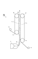
- FIG. 1 is a schematic configuration diagram showing a configuration of a manufacturing apparatus including a thermosetting resin foamed plate molding apparatus 100 according to an embodiment of the present invention.
- the manufacturing apparatus includes a mixer 1 that mixes a resin composition and a molding apparatus 100 that molds a thermosetting resin foamed plate.
- the molding apparatus 100 is a double conveyor type molding apparatus, and for example, a slat type double conveyor or an endless steel belt type double conveyor can be applied.
- a slat type conveyor is cited.
- the molding apparatus 100 is configured such that the thermosetting resin foam plate is formed on the upper side and the lower side of a conveyor 7 that is supported by the conveyor drive unit 4 and the conveyor driven unit 5. It arrange
- the conveyor 7 is a transport band wound around the conveyor driving unit 4 and the conveyor driven unit 5.
- the portion running between the upper end portion of the lower conveyor drive unit 4 and the upper end portion of the lower conveyor driven unit 5 constitutes a portion for conveying the object.
- the upper surface in the said part comprises a contact surface with a thermosetting resin foam board.
- the portion running between the lower end portion of the upper conveyor drive unit 4 and the lower end portion of the upper conveyor driven unit 5 constitutes a portion for conveying the object, and this portion
- the lower surface in the above constitutes a contact surface with the thermosetting resin foam plate.
- a face material 2 having air permeability is supplied between the upper conveyor 7 and the thermosetting resin foam plate 10, and air permeability is provided between the lower conveyor 7 and the thermosetting resin foam plate 10.
- the face material 3 having The molding apparatus 100 sandwiches the resin composition 6 supplied from the mixer 1 between the upper conveyor 7 and the lower conveyor 7 through the face materials 2 and 3, and the upper conveyor driving unit 4 and the lower conveyor 7.
- the thermosetting resin foamed plate 10 can be molded by driving the conveyor driving unit 4 in different directions and conveying the resin composition 6 while heating.
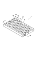
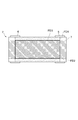
- the conveyor 7 is an integral type conveyor formed by connecting a plurality of slats ST to each other as shown in FIG.
- an opening 8 a is formed in the surface SF including the contact surface 9 that contacts the thermosetting resin foamed plate 10 by forming a through hole 8 that penetrates in the thickness direction in the conveyor 7. Is done.
- FIG. 3 is a view showing the characteristic configuration of the present invention in an easy-to-understand manner with respect to the overall shape of a part of the conveyor 7.
- the shape and thickness of the conveyor 7 and the arrangement, number and size of the through holes 8 are not limited to those shown in FIG.
- the shape and the like can be optimally set according to the molding apparatus to be applied.
- the conveyor 7 can be configured as shown in FIG.
- the conveyor 7 is configured by connecting a plurality of slats ST in which a plurality of through holes 8 are formed adjacent to each other.
- a plurality of slats ST may be connected to a chain that moves the slats ST, or the slats ST may be directly coupled to each other by coupling.
- the “surface” of the conveyor in the claims is defined as “an imaginary plane including a contact surface that comes into contact with the thermosetting resin foam plate during molding of the thermosetting resin foam plate on the conveyor” and “opening”
- the “part” is defined as “a region on the surface of the conveyor that is not in contact with the thermosetting resin foam plate during molding and is open to the outside of the conveyor in a region other than the surface of the conveyor”.
- the opening 8 a is formed by forming the through hole 8, as shown in FIG. 5A, a virtual plane including the contact surface 9 that contacts the thermosetting resin foamed plate 10.
- a certain surface SF corresponds to “surface” in the claims.
- the opening 8a that is formed by the upper end portion of the through hole 8 and is not in contact with the thermosetting resin foamed plate 10 on the surface SF of the conveyor 7 corresponds to the “opening” in the claims. .
- the opening 8a is opened to the outside of the conveyor 7 through the internal space of the through hole 8 on the surface 7a of the conveyor 7 other than the surface SF.
- a taper-shaped through-hole as shown in FIG.5 (b) may be sufficient. It may be a shape.
- the shape of the opening 8a can be a circular shape, an elliptical shape, an oval shape, etc., but a circular shape having a diameter of 1 mm or more and 10 mm or less is preferable, and a diameter of 5 mm or more and 8 mm is preferable for ease of processing of the opening metal.
- the following circular shape is more preferable.
- the opening of the conveyor may not be formed by a circular through hole.
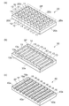
- the opening may be formed by forming a columnar protrusion 11 that protrudes upward from the upper surface 20 a of the conveyor 20.
- the surface SF that is a virtual plane including the contact surface 12 at the upper end of the protruding portion 11 that is a surface in contact with the thermosetting resin foam plate 10 is the “surface” in the claims. Applicable.
- region where the protrusion part 11 is not provided corresponds to the "opening part" in a claim.
- FIG. 6A is a schematic diagram showing the characteristic configuration of the present invention in an easy-to-understand manner with respect to the overall shape of a part of the conveyor 20.
- the shape and thickness of the conveyor 20 and the arrangement, number, and size of the protrusions 11 are not limited to those shown in FIG. The shape and the like can be optimally set according to the molding apparatus to be applied.
- the opening may be formed by forming a rectangular slit 13 penetrating in the thickness direction of the conveyor 30 as shown in FIG.
- the surface SF that is a virtual plane including the contact surface 14 that contacts the thermosetting resin foam plate 10 corresponds to the “surface” in the claims.
- the opening 13a which is formed by the upper end portion of the slit 13 and is not in contact with the thermosetting resin foamed plate 10 on the surface SF of the conveyor 30 corresponds to the “opening” in the claims.
- the opening 13a is opened to the outside of the conveyor 30 through the internal space of the slit 13 on the surface 30a of the conveyor 30 which is an area other than the surface SF.
- 6B is a schematic diagram showing the characteristic configuration of the present invention in an easy-to-understand manner with respect to the overall shape of a part of the conveyor 30, and the shape and thickness of the conveyor 30, the arrangement of the slits 13, and the like.
- the number and size are not limited to those shown in FIG.
- the shape and the like can be optimally set according to the molding apparatus to be applied.
- the opening may be formed by forming the slit 16 extending over the entire region in the width direction of the conveyor 40.
- the surface SF that is a virtual plane including the contact surface 17 that contacts the thermosetting resin foam plate 10 corresponds to the “surface” in the claims.
- region which is formed of the upper end part of the slit 13 and becomes non-contact with the thermosetting resin foam board 10 in the surface SF of the conveyor 40 corresponds to the "opening part" in a claim.
- FIG. 6C is a schematic diagram showing the characteristic configuration of the present invention in an easy-to-understand manner with respect to the overall shape of a part of the conveyor 40.
- the shape and thickness of the conveyor 40, the arrangement of the slits 16 and the like The number and size are not limited to those shown in FIG.
- the shape and the like can be optimally set according to the molding apparatus to be applied.
- the opening rate of the conveyor is set to 15% or more and 80% or less.
- the lower limit of the opening ratio is preferably 20% or more, more preferably 25%, from the viewpoint of securing the compressive strength of the thermosetting resin foam plate obtained using this apparatus, and more preferably 25%, depending on the residual moisture content. From the viewpoint of dimensional stability, it is particularly preferably 30% or more.
- the upper limit of the aperture ratio is preferably 75% or less, more preferably 70% or less, and particularly preferably 65% or less, from the viewpoint of ease and economy in manufacturing the present apparatus.
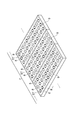
- the opening ratio of the opening portion is a ratio of the total area of the opening portion to the total area of the foamed plate molding portion on the conveyor surface, and is represented by the formula (1).
- the foam plate forming part on the conveyor surface is a region facing the thermosetting resin foam plate 10 on the conveyor surface. As shown in FIG. A region FD1 (region shown by satin in the drawing) where the parallelism is maintained and a region FD2 (region shown by diagonal lines in the drawing) through which the thermosetting resin foam plate 10 passes are overlapping FD3.
- the total area of the foam plate forming part on the conveyor surface is the total area of the contact surface with the thermosetting resin foam plate 10 in the foam plate forming part on the conveyor surface. And the sum.
- Opening ratio ⁇ (total area of the opening in the foam plate forming part on the conveyor surface) / (total area of the foam plate forming part on the conveyor surface) ⁇ ⁇ 100 [%]
- the molding temperature during foaming and curing is preferably 50 ° C. or higher and 120 ° C. or lower. If it is less than 50 ° C., the production rate is low, which is not preferable. If it exceeds 120 ° C., the amount of heat generated inside the foam increases and the temperature rises too much, so that the foam film of the thermosetting resin foam plate breaks. It becomes easy and is not preferable.
- the thermosetting resin foam plate 10 is a foam plate made of a thermosetting resin such as phenol resin foam, urethane foam, isocyanurate, etc., and is a resin obtained by adding appropriate amounts of a foaming agent and a curing agent to the thermosetting resin. It is obtained by foaming and curing the composition 6.
- a surfactant, a plasticizer, a bulking agent, and the like can be added to the resin composition 6 as necessary.
- the thermosetting resin suitable for the molding apparatus 100 having an opening on the conveyor surface as in the present invention is a thermosetting resin that dissipates volatiles such as a foaming agent during molding, such as polyurethane resin, isocyanurate resin, phenol. Resin.
- the phenol resin is preferably used in the double conveyor type molding apparatus because condensed water is generated in addition to the dissipation of the foaming agent during foam molding.
- the phenol resin is a modified phenol resin containing at least one of urea, melamine, and dicyandiamide.
- the foaming agent used in the production of the phenolic resin foam plate is preferably a hydrocarbon or a chlorinated hydrocarbon.
- a hydrocarbon or a chlorinated hydrocarbon normal butane, isobutane, cyclobutane, normal pentane, isopentane, cyclopentane, neopentane, normal hexane, isohexane, 2,2-dimethylbutane, 2,3-dimethylbutane, cyclohexane, monochloromethyl, monochloroethyl, 1 -Chloropropane, 2-chloropropane and the like.
- normal pentane, isopentane, cyclopentane, neopentane pentane and normal butane, isobutane, cyclobutane butane have good foaming characteristics in the production of the phenolic resin foam of the present invention, and have a comparative thermal conductivity. It is particularly preferable because of its small size. Furthermore, normal pentane, isopentane, cyclopentane, neopentane pentane and normal butane, isobutane, cyclobutane butane are particularly preferred because of their low global warming potential.
- the face materials 2 and 3 used in the present invention are preferably air-permeable flexible face materials.
- synthetic fiber nonwoven fabrics, glass fiber papers, and papers are preferable from the viewpoint of ease of handling as foamed plates and economy. Is preferred. More specifically, non-woven fabric, woven fabric, glass fiber non-woven fabric, metal-deposited non-woven fabric, calcium carbonate paper, aluminum hydroxide paper, magnesium silicate paper, perforated metal foil, perforated material containing at least one of polyester, nylon and polypropylene A metal foil multilayer sheet is preferred.
- the perforated metal foil multilayer sheet is a woven fabric, knitted fabric or knitted fabric comprising a perforated metal foil and any one of polyester fiber, vinylon fiber, polypropylene fiber, polyamide fiber, glass fiber, carbon fiber, and silicon carbide fiber.
- a composite with cloth, nonwoven fabric, or kraft paper is preferred.
- a resin composition is discharged onto a lower surface material that travels, and then a surface material is coated thereon, thereby providing a surface material on both surface layers.
- a curable resin foam board laminate is obtained.
- the perforated metal foil preferably contains at least one of copper foil and aluminum copper foil.
- the basis weight of the nonwoven fabric is preferably 15 g / m 2 or more and 80 g / m 2 or less. If the basis weight is less than 15 g / m 2, the thermosetting resin oozes out to the face material at the time of foaming, and not only the surface quality is greatly impaired, but also the mold releasability from the conveyor immediately after the double conveyor molding is lowered, and the thermosetting. There is a risk of damage to the foamed resin foam board. If the basis weight exceeds 80 g / m 2, the thermosetting resin does not sufficiently adhere to the face material, and the face material may be peeled off from the thermosetting resin foamed plate immediately after molding.
- thermosetting resin By preheating the surface material, the curing of the thermosetting resin is accelerated and the viscosity is increased, so that bleeding is reduced and a nonwoven fabric having a basis weight of 10 g / m 2 or more can be used.
- the basis weight is the weight per unit area.
- thermosetting resin foam board using the molding apparatus 100 described above.
- a resin composition composed of a thermosetting resin, a foaming agent, and a curing agent is mixed in the mixer 1, and the resin composition 6 is continuously supplied on the face material 3 that is fed onto the lower conveyor 7 and travels.
- the upper surface of the resin composition 6 is covered with the face material 2 which is supplied to the lower surface side of the upper conveyor 7 and travels, and is sandwiched between the upper and lower conveyors 7 of the molding apparatus 100 and passed while being heated.
- the thermosetting resin foam board 10 is manufactured by molding and curing the resin composition 6.
- the molding is performed by using the conveyor 7 having an opening with an opening ratio of 15% to 80%. While being molded and cured by the conveyor 7, water vapor and foaming gas in the thermosetting resin composition can be effectively released from the opening. Therefore, it is possible to dry at high speed without making unnecessary face materials into multiple layers, and it is possible to manufacture the thermosetting resin foam plate 10 more efficiently and stably.
- thermosetting resin a thermosetting resin
- the viscosity at 40 ° C. was 5,800 mPa ⁇ s. This is designated as phenol resin AU.
- Example 1 A block copolymer of ethylene oxide-propylene oxide (manufactured by BASF, Pluronic F-127) as a surfactant was mixed with 100 parts by weight of phenol resin AU at a ratio of 2.0 parts by weight. Based on 100 parts by weight of this phenolic resin, it comprises 7 parts by weight of a mixture of 50% by weight of isopentane and 50% by weight of isobutane as a blowing agent, and 11 parts by weight of a mixture of 80% by weight of xylene sulfonic acid and 20% by weight of diethylene glycol as an acid curing catalyst. The composition was supplied to a mixer whose temperature was adjusted to 25 ° C. so that the resin flow rate after mixing was 52 kg / hr, and then the resin composition was discharged from the mixer, onto the moving lower surface material. Supplied.
- phenol resin AU Based on 100 parts by weight of this phenolic resin, it comprises 7 parts by weight of a mixture of 50% by weight of isopentane and 50%
- a polyester non-woven fabric (“Spunbond E05030” manufactured by Asahi Kasei Fibers Co., Ltd., basis weight 30 g / m 2, thickness 0.15 mm) was used.
- the resin composition supplied on the lower surface material is coated with the upper surface material, and then sandwiched between the upper and lower surface materials, the ambient temperature is set to 80 ° C., and the upper and lower conveyors have openings with an opening ratio of 65%. After being sent to a conveyor and cured at each residence time of 30 minutes, it was post-cured and heated in an oven at 105 ° C. for 2 hours to obtain a foamed plate. In addition, evaluation of the foam board was performed about the foam board obtained immediately after the double conveyor shaping
- Example 2 A foamed plate was obtained in the same manner as in Example 1 except that the aperture ratio was 50%.
- Example 3 A foamed plate was obtained in the same manner as in Example 1 except that the aperture ratio was 30%.
- Example 4 A foamed plate was obtained in the same manner as in Example 1 except that the aperture ratio was 20%.
- Example 5 A foamed plate was obtained in the same manner as in Example 3 except that the basis weight of the face material was 70 g / m2.
- Example 6 A foamed plate was obtained in the same manner as in Example 4 except that the basis weight of the face material was 70 g / m2.
- Comparative Example 2 A foamed plate was obtained in the same manner as in Comparative Example 1 except that the molding time was 60 minutes.
- Comparative Example 3 A foamed plate was obtained in the same manner as in Comparative Example 1 except that the aperture ratio was 4% and the molding time was 90 minutes.
- Comparative Example 4 A foamed plate was obtained in the same manner as in Comparative Example 1 except that the aperture ratio was 0% and the molding time was 90 minutes.
- Example 6 A foamed plate was obtained in the same manner as in Example 1 except that the basis weight of the face material was 70 g / m 2 and the aperture ratio was 14%.
- [Moisture content of foam plate] A value obtained by measuring, as a moisture content, a value obtained by subtracting a sample weight after post-curing heating from a sample weight immediately after molding from a 20 cm square foamed plate, and dividing the value by the sample weight after post-curing heat. .
- [Density of foam plate] A value obtained by measuring a weight and an apparent volume after removing a surface material of a 20 cm square foam plate as a sample, and measured according to JIS-K-7222.
- [Closed cell ratio of foam plate] A cylindrical sample with a diameter of 35 mm to 36 mm is punched from a foam plate with a cork borer and cut to a height of 30 mm to 40 mm, and then the sample volume is measured by the standard usage method of an air-comparing hydrometer (Tokyo Science, Model 1000) Measure. The value obtained by subtracting the volume of the bubble wall calculated from the sample weight and resin density from the sample volume was divided by the apparent volume calculated from the outer dimensions of the sample, and was measured according to ASTM-D-2856. Here, in the case of a phenol resin, the density was 1.3 kg / L.
- Table 1 shows the aperture ratio, molding temperature, molding time, and evaluation results of the obtained foamed plate.
- each of the foamed plates according to Examples 1 to 6 has a lower moisture content and higher density, closed cell rate, and compressive strength than the foamed plates according to Comparative Examples 1 to 4.
- the overall evaluation is ⁇ .
- Comparative Examples 5 and 6 the moisture content exceeded 1.0%, and the overall evaluation was ⁇ .
- the present invention can be used for forming a thermosetting resin foam plate.
Landscapes
- Engineering & Computer Science (AREA)
- Textile Engineering (AREA)
- Health & Medical Sciences (AREA)
- Toxicology (AREA)
- Casting Or Compression Moulding Of Plastics Or The Like (AREA)
- Manufacture Of Porous Articles, And Recovery And Treatment Of Waste Products (AREA)
- Laminated Bodies (AREA)
- Molding Of Porous Articles (AREA)
Abstract
Description
反応器に52重量%ホルムアルデヒド3500kgと99重量%フェノール2510kgを仕込み、プロペラ回転式の攪拌機により攪拌し、温調機により反応器内部液温度を40℃に調整した。次いで50重量%水酸化ナトリウム水溶液を加えながら昇温して、反応を行わせた。オストワルド粘度が60センチストークス(=60×10-6m2/s、25℃における測定値)に到達した段階で、反応液を冷却し、尿素を570kg(ホルムアルデヒド仕込み量の15モル%に相当)添加した。その後、反応液を30℃まで冷却し、パラトルエンスルホン酸一水和物の50重量%水溶液でpHを6.4に中和した。
フェノール樹脂A-U:100重量部に対して、界面活性剤としてエチレンオキサイド-プロピレンオキサイドのブロック共重合体(BASF製、プルロニックF-127)を2.0重量部の割合で混合した。このフェノール樹脂100重量部に対して、発泡剤としてイソペンタン50重量%とイソブタン50重量%の混合物7重量部、酸硬化触媒としてキシレンスルホン酸80重量%とジエチレングリコール20重量%の混合物11重量部からなる組成物を25℃に温調した混合機に、混合後の樹脂流量が52kg/hrとなるように供給し、続いて混合機から該樹脂組成物を吐出させて、移動する下表面材上に供給した。
開口率を50%とする以外は、実施例1と同様にして発泡板を得た。
開口率を30%とする以外は、実施例1と同様にして発泡板を得た。
開口率を20%とする以外は、実施例1と同様にして発泡板を得た。
面材坪量を70g/m2とする以外は、実施例3と同様にして発泡板を得た。
面材坪量を70g/m2とする以外は、実施例4と同様にして発泡板を得た。
開口率を10%とする以外は、実施例1と同様にして発泡板を得た。
成形時間を60分とする以外は、比較例1と同様にして発泡板を得た。
開口率を4%とし、成形時間90分とする以外は、比較例1と同様にして発泡板を得た。
開口率を0%とし、成形時間90分とする以外は、比較例1と同様にして発泡板を得た。
開口率を14%とする以外は、実施例1と同様にして発泡板を得た。
面材坪量を70g/m2とし、開口率を14%とする以外は、実施例1と同様にして発泡板を得た。
20cm角の発泡板を試料とし、成形直後の試料重量から後硬化加熱後の試料重量を差し引いた値を後硬化熱後の試料重量で割った値を水分率として測定して求めた値である。
20cm角の発泡板を試料とし、この試料の表面材を取り除いて重量と見かけ容積を測定して求めた値であり、JIS-K-7222に従い測定した。
発泡板より直径35mm~36mmの円筒試料をコルクボーラーで刳り貫き、高さ30mm~40mmに切りそろえた後、空気比較式比重計(東京サイエンス社製、1,000型)の標準使用方法により試料容積を測定する。その試料容積から、試料重量と樹脂密度から計算した気泡壁の容積を差し引いた値を、試料の外寸から計算した見かけの容積で割った値であり、ASTM-D-2856に従い測定した。ここでフェノール樹脂の場合、その密度は1.3kg/Lとした。
発泡板を10cm角で切り出し、JIS-K7220に従い、規定ひずみを0.05として測定した。
発泡板の水分率が1.0%以下であり、圧縮強度が14.0N/cm2以上のものを○どちらか一つの条件を満足するものを△、どちらも満足しないものを×とした。

Claims (9)
- 熱硬化性樹脂発泡板を成形するダブルコンベア型の熱硬化性樹脂発泡板の成形装置において、
走行するコンベアは表面に開口部を有し、前記開口部の開口率が15%以上80%以下であることを特徴とする熱硬化性樹脂発泡板の成形装置。 - 前記開口部は、前記コンベアに貫通孔を形成することによって形成されていることを特徴とする請求項1記載の熱硬化性樹脂発泡板の成形装置。
- 少なくとも熱硬化性樹脂、発泡剤、及び硬化剤からなる樹脂組成物を混合機にて混合し、
通気性を有する可撓性面材上に前記樹脂組成物を連続的に吐出すると共に、通気性を有する可撓性面材で前記樹脂組成物の上面を被覆し、
請求項1記載の成形装置を通過させて前記樹脂組成物を成形硬化させることによって熱硬化性樹脂発泡板を製造することを特徴とする熱硬化性樹脂発泡板の製造方法。 - 前記熱硬化性樹脂が少なくともフェノール樹脂、ウレタン樹脂、イソシアヌレート樹脂のいずれか一以上を含むことを特徴とする請求項3記載の熱硬化性樹脂発泡板の製造方法。
- 前記フェノール樹脂が少なくとも尿素、メラミン、ジシアンジアミドのいずれか一以上を含む変性フェノール樹脂であることを特徴とする請求項4記載の熱硬化性樹脂発泡板の製造方法。
- 前記通気性を有する可撓性面材がポリエステル、ナイロン、ポリプロピレンの少なくとも一つを含む不織布、織布、ガラス繊維不織布、金属蒸着不織布、炭酸カルシウム紙、水酸化アルミニウム紙、珪酸マグネシウム紙、孔あき金属箔、孔あき金属箔複層シートであることを特徴とする請求項3記載の熱硬化性樹脂発泡板の製造方法。
- 前記孔あき金属箔が少なくとも銅箔、アルミ銅箔の一つ以上を含むことを特徴とする請求項6記載の熱硬化性樹脂発泡板の製造方法。
- 前記孔あき金属箔複層シートが前記孔あき金属箔と、ポリエステル繊維、ビニロン繊維、ポリプロピレン繊維、ポリアミド繊維、ガラス繊維、炭素繊維、炭化珪素繊維のいずれか一つを含む織布、編布、編織布、不織布、またはクラフト紙との複合体であることを特徴とする請求項6記載の熱硬化性樹脂発泡板の製造方法。
- 前記不織布の坪量が15g/m2以上80g/m2以下であることを特徴とする請求項6記載の熱硬化性樹脂発泡板の製造方法。
Priority Applications (8)
| Application Number | Priority Date | Filing Date | Title |
|---|---|---|---|
| US13/266,483 US8877106B2 (en) | 2009-04-28 | 2010-04-27 | Device for forming thermosetting resin foam plate and method of manufacturing thermosetting resin foam plate |
| KR1020117013111A KR101338763B1 (ko) | 2009-04-28 | 2010-04-27 | 열경화성 수지 발포판의 성형 장치 및 열경화성 수지 발포판의 제조 방법 |
| RU2011143519/05A RU2531182C2 (ru) | 2009-04-28 | 2010-04-27 | Устройство для формования пенопластовой плиты из термореактивного полимера и способ изготовления пенопластовой плиты из термореактивного полимера |
| EP10769722.9A EP2425954B1 (en) | 2009-04-28 | 2010-04-27 | Device for forming thermosetting resin foam plate and method of manufacturing thermosetting resin foam plate |
| JP2011511401A JP5551155B2 (ja) | 2009-04-28 | 2010-04-27 | 熱硬化性樹脂発泡板の成形装置及び熱硬化性樹脂発泡板の製造方法 |
| MX2011011204A MX2011011204A (es) | 2009-04-28 | 2010-04-27 | Dispositivo para formar una placa de espuma de resina termoendurecible y metodo para fabricar una placa de espuma de resina termoendurecible. |
| CA2759704A CA2759704C (en) | 2009-04-28 | 2010-04-27 | Device for forming thermosetting resin foam plate and method of manufacturing thermosetting resin foam plate |
| CN201080018578.XA CN102414002B (zh) | 2009-04-28 | 2010-04-27 | 热固性树脂泡沫板的成形装置及热固性树脂泡沫板的制造方法 |
Applications Claiming Priority (2)
| Application Number | Priority Date | Filing Date | Title |
|---|---|---|---|
| JP2009109424 | 2009-04-28 | ||
| JP2009-109424 | 2009-04-28 |
Publications (1)
| Publication Number | Publication Date |
|---|---|
| WO2010126024A1 true WO2010126024A1 (ja) | 2010-11-04 |
Family
ID=43032169
Family Applications (1)
| Application Number | Title | Priority Date | Filing Date |
|---|---|---|---|
| PCT/JP2010/057421 Ceased WO2010126024A1 (ja) | 2009-04-28 | 2010-04-27 | 熱硬化性樹脂発泡板の成形装置及び熱硬化性樹脂発泡板の製造方法 |
Country Status (10)
| Country | Link |
|---|---|
| US (1) | US8877106B2 (ja) |
| EP (1) | EP2425954B1 (ja) |
| JP (1) | JP5551155B2 (ja) |
| KR (1) | KR101338763B1 (ja) |
| CN (1) | CN102414002B (ja) |
| CA (1) | CA2759704C (ja) |
| MX (1) | MX2011011204A (ja) |
| RU (1) | RU2531182C2 (ja) |
| TW (1) | TW201100227A (ja) |
| WO (1) | WO2010126024A1 (ja) |
Cited By (4)
| Publication number | Priority date | Publication date | Assignee | Title |
|---|---|---|---|---|
| KR101197253B1 (ko) | 2011-01-20 | 2012-11-05 | (주)지이후렌드 | 페놀 폼 샌드위치 패널 및 그 제조방법 |
| JP2018123292A (ja) * | 2017-01-27 | 2018-08-09 | 旭化成建材株式会社 | フェノール樹脂発泡体積層板及びその製造方法 |
| JP2018165049A (ja) * | 2017-03-28 | 2018-10-25 | 旭化成建材株式会社 | フェノール樹脂発泡体積層板及びその製造方法 |
| JP2019072922A (ja) * | 2017-10-16 | 2019-05-16 | 旭化成建材株式会社 | フェノール樹脂発泡体積層板 |
Families Citing this family (4)
| Publication number | Priority date | Publication date | Assignee | Title |
|---|---|---|---|---|
| CA2933690A1 (en) * | 2013-12-19 | 2015-06-25 | Dow Global Technologies Llc | Rigid thermoplastic foam densification process and composite structures incorporating the densified rigid thermoplastic foam |
| CN105922491A (zh) * | 2016-05-18 | 2016-09-07 | 东莞铭丰生物质科技有限公司 | 一种包装盒的制造方法及制造装置 |
| CN106671484B (zh) * | 2017-02-28 | 2023-08-08 | 明达塑胶科技(苏州)有限公司 | 一种可一次性制作的不织布气泡袋制造装置 |
| CN110606762B (zh) * | 2019-09-27 | 2021-12-14 | 长沙晟天新材料有限公司 | 一种碳纤维复合材料颅骨修补片及其制备方法 |
Citations (12)
| Publication number | Priority date | Publication date | Assignee | Title |
|---|---|---|---|---|
| JPS49133484A (ja) * | 1972-08-28 | 1974-12-21 | ||
| JPS5761534A (en) * | 1980-09-30 | 1982-04-14 | Matsushita Electric Works Ltd | Foam molding machine for heat insulating building plate |
| JPS58112737A (ja) * | 1981-12-26 | 1983-07-05 | アキレス株式会社 | 積層体の製造方法 |
| JPH035973B2 (ja) | 1982-08-02 | 1991-01-28 | Mitsui Petrochemical Ind | |
| JPH05269722A (ja) * | 1992-03-26 | 1993-10-19 | Daiwa House Ind Co Ltd | 無機質パネルの製造方法 |
| JPH05309756A (ja) * | 1992-05-08 | 1993-11-22 | Asahi Chem Ind Co Ltd | 発泡板の連続成形装置 |
| JP2561576B2 (ja) | 1991-06-18 | 1996-12-11 | 株式会社クボタ | 熱硬化性樹脂発泡板の製造装置 |
| JP2561575B2 (ja) | 1991-06-18 | 1996-12-11 | 株式会社クボタ | 熱硬化性樹脂発泡板の製造装置 |
| JPH09277278A (ja) * | 1996-04-09 | 1997-10-28 | Idemitsu Petrochem Co Ltd | 多孔質成形体の製造方法 |
| JP2002240073A (ja) * | 2001-02-16 | 2002-08-28 | Jsp Corp | ポリオレフィン系樹脂発泡成形体の製造方法及び製造装置 |
| JP2002292651A (ja) * | 2001-03-29 | 2002-10-09 | Nitto Boseki Co Ltd | 樹脂発泡体の製造方法及び樹脂発泡体 |
| JP2005131820A (ja) * | 2003-10-28 | 2005-05-26 | Nitto Boseki Co Ltd | フェノール樹脂発泡体積層板及びフェノール樹脂発泡体積層板の製造方法 |
Family Cites Families (16)
| Publication number | Priority date | Publication date | Assignee | Title |
|---|---|---|---|---|
| US3999230A (en) * | 1971-12-02 | 1976-12-28 | Dynamit Nobel Aktiengesellschaft | Apparatus for the continuous manufacture of phenolic resin foam in endless sheets |
| US3986918A (en) * | 1972-08-28 | 1976-10-19 | Erling Berner | Apparatus for forming laminated molded bodies |
| DE2335892A1 (de) * | 1973-07-14 | 1975-01-30 | Basf Ag | Vorrichtung zur kontinuierlichen herstellung von endlosen schaumstoffstraengen |
| GB1521821A (en) | 1975-01-28 | 1978-08-16 | Upjohn Co | Continuous production of elongate foamed products |
| US5149394A (en) * | 1988-10-14 | 1992-09-22 | Kurt Held | Method and apparatus for continuously fabricating laminates |
| US5171756A (en) * | 1991-07-31 | 1992-12-15 | Crain Industries, Inc. | Three stage cooling of porous materials |
| KR940007523B1 (ko) | 1992-03-05 | 1994-08-19 | 서건희 | 건재의 연속 성형 장치 및 그 방법 |
| KR960009114B1 (ko) | 1992-03-05 | 1996-07-13 | 서건희 | 건재의 연속 성형 장치 및 그 방법 |
| JPH09133484A (ja) | 1995-11-09 | 1997-05-20 | Furukawa Electric Co Ltd:The | 空調用熱交換器の液面調節器 |
| DE19543276C1 (de) | 1995-11-20 | 1997-02-06 | Continental Ag | Reifenvulkanisationsform mit Entlüftung |
| JP3775612B2 (ja) | 1996-12-24 | 2006-05-17 | 株式会社ジェイエスピー | 発泡成形体の製造方法及び製造装置 |
| JP3837226B2 (ja) | 1998-02-05 | 2006-10-25 | 旭化成建材株式会社 | フェノール樹脂発泡体積層板およびその製造方法 |
| US6140383A (en) * | 1998-04-23 | 2000-10-31 | Johns Manville International, Inc. | Process for manufacturing rigid polyisocyanurate foam products |
| DE10343745A1 (de) * | 2003-09-22 | 2005-04-21 | Hennecke Gmbh | Verfahren zur Herstellung von Polyurethan-Sandwichelementen |
| US7524403B2 (en) * | 2006-04-28 | 2009-04-28 | Voith Paper Patent Gmbh | Forming fabric and/or tissue molding belt and/or molding belt for use on an ATMOS system |
| ITMI20071281A1 (it) * | 2007-06-26 | 2008-12-27 | Gilanberry Trading Ltd | Apparecchiatura e metodo per la formatura in continuo di un elemento continuo di materia plastica espansa, impianto comprendente detta apparecchiatura ed elemento costruttivo di materia plastica espansa |
-
2010
- 2010-04-27 WO PCT/JP2010/057421 patent/WO2010126024A1/ja not_active Ceased
- 2010-04-27 CN CN201080018578.XA patent/CN102414002B/zh active Active
- 2010-04-27 MX MX2011011204A patent/MX2011011204A/es not_active Application Discontinuation
- 2010-04-27 US US13/266,483 patent/US8877106B2/en active Active
- 2010-04-27 JP JP2011511401A patent/JP5551155B2/ja active Active
- 2010-04-27 CA CA2759704A patent/CA2759704C/en active Active
- 2010-04-27 EP EP10769722.9A patent/EP2425954B1/en active Active
- 2010-04-27 RU RU2011143519/05A patent/RU2531182C2/ru active
- 2010-04-27 KR KR1020117013111A patent/KR101338763B1/ko active Active
- 2010-04-28 TW TW099113554A patent/TW201100227A/zh unknown
Patent Citations (12)
| Publication number | Priority date | Publication date | Assignee | Title |
|---|---|---|---|---|
| JPS49133484A (ja) * | 1972-08-28 | 1974-12-21 | ||
| JPS5761534A (en) * | 1980-09-30 | 1982-04-14 | Matsushita Electric Works Ltd | Foam molding machine for heat insulating building plate |
| JPS58112737A (ja) * | 1981-12-26 | 1983-07-05 | アキレス株式会社 | 積層体の製造方法 |
| JPH035973B2 (ja) | 1982-08-02 | 1991-01-28 | Mitsui Petrochemical Ind | |
| JP2561576B2 (ja) | 1991-06-18 | 1996-12-11 | 株式会社クボタ | 熱硬化性樹脂発泡板の製造装置 |
| JP2561575B2 (ja) | 1991-06-18 | 1996-12-11 | 株式会社クボタ | 熱硬化性樹脂発泡板の製造装置 |
| JPH05269722A (ja) * | 1992-03-26 | 1993-10-19 | Daiwa House Ind Co Ltd | 無機質パネルの製造方法 |
| JPH05309756A (ja) * | 1992-05-08 | 1993-11-22 | Asahi Chem Ind Co Ltd | 発泡板の連続成形装置 |
| JPH09277278A (ja) * | 1996-04-09 | 1997-10-28 | Idemitsu Petrochem Co Ltd | 多孔質成形体の製造方法 |
| JP2002240073A (ja) * | 2001-02-16 | 2002-08-28 | Jsp Corp | ポリオレフィン系樹脂発泡成形体の製造方法及び製造装置 |
| JP2002292651A (ja) * | 2001-03-29 | 2002-10-09 | Nitto Boseki Co Ltd | 樹脂発泡体の製造方法及び樹脂発泡体 |
| JP2005131820A (ja) * | 2003-10-28 | 2005-05-26 | Nitto Boseki Co Ltd | フェノール樹脂発泡体積層板及びフェノール樹脂発泡体積層板の製造方法 |
Non-Patent Citations (1)
| Title |
|---|
| See also references of EP2425954A4 * |
Cited By (6)
| Publication number | Priority date | Publication date | Assignee | Title |
|---|---|---|---|---|
| KR101197253B1 (ko) | 2011-01-20 | 2012-11-05 | (주)지이후렌드 | 페놀 폼 샌드위치 패널 및 그 제조방법 |
| JP2018123292A (ja) * | 2017-01-27 | 2018-08-09 | 旭化成建材株式会社 | フェノール樹脂発泡体積層板及びその製造方法 |
| JP2018165049A (ja) * | 2017-03-28 | 2018-10-25 | 旭化成建材株式会社 | フェノール樹脂発泡体積層板及びその製造方法 |
| JP7027078B2 (ja) | 2017-03-28 | 2022-03-01 | 旭化成建材株式会社 | フェノール樹脂発泡体積層板及びその製造方法 |
| JP2019072922A (ja) * | 2017-10-16 | 2019-05-16 | 旭化成建材株式会社 | フェノール樹脂発泡体積層板 |
| JP6993165B2 (ja) | 2017-10-16 | 2022-01-13 | 旭化成建材株式会社 | フェノール樹脂発泡体積層板 |
Also Published As
| Publication number | Publication date |
|---|---|
| US20120043681A1 (en) | 2012-02-23 |
| CN102414002B (zh) | 2016-04-06 |
| EP2425954A1 (en) | 2012-03-07 |
| US8877106B2 (en) | 2014-11-04 |
| JPWO2010126024A1 (ja) | 2012-11-01 |
| EP2425954A4 (en) | 2013-07-24 |
| TW201100227A (en) | 2011-01-01 |
| MX2011011204A (es) | 2012-01-25 |
| EP2425954B1 (en) | 2016-03-30 |
| JP5551155B2 (ja) | 2014-07-16 |
| CN102414002A (zh) | 2012-04-11 |
| KR20110093877A (ko) | 2011-08-18 |
| CA2759704A1 (en) | 2010-11-04 |
| RU2011143519A (ru) | 2013-06-10 |
| KR101338763B1 (ko) | 2013-12-06 |
| CA2759704C (en) | 2015-06-02 |
| RU2531182C2 (ru) | 2014-10-20 |
Similar Documents
| Publication | Publication Date | Title |
|---|---|---|
| JP5551155B2 (ja) | 熱硬化性樹脂発泡板の成形装置及び熱硬化性樹脂発泡板の製造方法 | |
| JP3837226B2 (ja) | フェノール樹脂発泡体積層板およびその製造方法 | |
| JP5220622B2 (ja) | 空所部分を有する多層フォーム複合材料 | |
| US9957368B2 (en) | Phenolic resin foam board, and method for manufacturing same | |
| CN101374644A (zh) | 酚醛泡沫板 | |
| JP6081188B2 (ja) | フェノール樹脂発泡体積層板とその製造方法 | |
| JP5060688B2 (ja) | 樹脂発泡体 | |
| JP4925390B2 (ja) | フェノール樹脂発泡体の製造方法 | |
| KR20160025704A (ko) | 단열재 및 그 제조방법 | |
| JP5677893B2 (ja) | フェノール樹脂発泡体積層板及びその製造方法 | |
| CN103547617A (zh) | 包含中空微球的三聚氰胺-甲醛泡沫 | |
| JP2005231118A (ja) | フェノール樹脂発泡体積層板およびその製造方法 | |
| KR101684694B1 (ko) | 저비중 불연성 복합재료의 제조방법 | |
| JP2015151484A (ja) | フェノール樹脂発泡体の製造方法 | |
| JP7027078B2 (ja) | フェノール樹脂発泡体積層板及びその製造方法 | |
| TWI884778B (zh) | 酚樹脂發泡體及其製造方法 | |
| TWI801964B (zh) | 酚樹脂發泡體 | |
| JP2019072922A (ja) | フェノール樹脂発泡体積層板 | |
| JPS5924638A (ja) | フエノ−ル樹脂発泡体の連続成形方法 | |
| JPH04249117A (ja) | フェノール樹脂発泡複合体の製造方法 |
Legal Events
| Date | Code | Title | Description |
|---|---|---|---|
| WWE | Wipo information: entry into national phase |
Ref document number: 201080018578.X Country of ref document: CN |
|
| 121 | Ep: the epo has been informed by wipo that ep was designated in this application |
Ref document number: 10769722 Country of ref document: EP Kind code of ref document: A1 |
|
| ENP | Entry into the national phase |
Ref document number: 2011511401 Country of ref document: JP Kind code of ref document: A |
|
| ENP | Entry into the national phase |
Ref document number: 20117013111 Country of ref document: KR Kind code of ref document: A |
|
| WWE | Wipo information: entry into national phase |
Ref document number: 2759704 Country of ref document: CA |
|
| WWE | Wipo information: entry into national phase |
Ref document number: 4387/KOLNP/2011 Country of ref document: IN Ref document number: MX/A/2011/011204 Country of ref document: MX Ref document number: 2010769722 Country of ref document: EP |
|
| WWE | Wipo information: entry into national phase |
Ref document number: 13266483 Country of ref document: US |
|
| NENP | Non-entry into the national phase |
Ref country code: DE |
|
| ENP | Entry into the national phase |
Ref document number: 2011143519 Country of ref document: RU Kind code of ref document: A |