WO2010143468A1 - トルクリミッタ装置 - Google Patents
トルクリミッタ装置 Download PDFInfo
- Publication number
- WO2010143468A1 WO2010143468A1 PCT/JP2010/056774 JP2010056774W WO2010143468A1 WO 2010143468 A1 WO2010143468 A1 WO 2010143468A1 JP 2010056774 W JP2010056774 W JP 2010056774W WO 2010143468 A1 WO2010143468 A1 WO 2010143468A1
- Authority
- WO
- WIPO (PCT)
- Prior art keywords
- torque limiter
- drive member
- friction
- transmission
- torque
- Prior art date
- Legal status (The legal status is an assumption and is not a legal conclusion. Google has not performed a legal analysis and makes no representation as to the accuracy of the status listed.)
- Ceased
Links
Images






Classifications
-
- F—MECHANICAL ENGINEERING; LIGHTING; HEATING; WEAPONS; BLASTING
- F16—ENGINEERING ELEMENTS AND UNITS; GENERAL MEASURES FOR PRODUCING AND MAINTAINING EFFECTIVE FUNCTIONING OF MACHINES OR INSTALLATIONS; THERMAL INSULATION IN GENERAL
- F16D—COUPLINGS FOR TRANSMITTING ROTATION; CLUTCHES; BRAKES
- F16D7/00—Slip couplings, e.g. slipping on overload, for absorbing shock
- F16D7/02—Slip couplings, e.g. slipping on overload, for absorbing shock of the friction type
- F16D7/024—Slip couplings, e.g. slipping on overload, for absorbing shock of the friction type with axially applied torque limiting friction surfaces
- F16D7/025—Slip couplings, e.g. slipping on overload, for absorbing shock of the friction type with axially applied torque limiting friction surfaces with flat clutching surfaces, e.g. discs
-
- F—MECHANICAL ENGINEERING; LIGHTING; HEATING; WEAPONS; BLASTING
- F16—ENGINEERING ELEMENTS AND UNITS; GENERAL MEASURES FOR PRODUCING AND MAINTAINING EFFECTIVE FUNCTIONING OF MACHINES OR INSTALLATIONS; THERMAL INSULATION IN GENERAL
- F16D—COUPLINGS FOR TRANSMITTING ROTATION; CLUTCHES; BRAKES
- F16D3/00—Yielding couplings, i.e. with means permitting movement between the connected parts during the drive
- F16D3/02—Yielding couplings, i.e. with means permitting movement between the connected parts during the drive adapted to specific functions
- F16D3/14—Yielding couplings, i.e. with means permitting movement between the connected parts during the drive adapted to specific functions combined with a friction coupling for damping vibration or absorbing shock
-
- F—MECHANICAL ENGINEERING; LIGHTING; HEATING; WEAPONS; BLASTING
- F16—ENGINEERING ELEMENTS AND UNITS; GENERAL MEASURES FOR PRODUCING AND MAINTAINING EFFECTIVE FUNCTIONING OF MACHINES OR INSTALLATIONS; THERMAL INSULATION IN GENERAL
- F16F—SPRINGS; SHOCK-ABSORBERS; MEANS FOR DAMPING VIBRATION
- F16F15/00—Suppression of vibrations in systems; Means or arrangements for avoiding or reducing out-of-balance forces, e.g. due to motion
- F16F15/10—Suppression of vibrations in rotating systems by making use of members moving with the system
- F16F15/12—Suppression of vibrations in rotating systems by making use of members moving with the system using elastic members or friction-damping members, e.g. between a rotating shaft and a gyratory mass mounted thereon
- F16F15/131—Suppression of vibrations in rotating systems by making use of members moving with the system using elastic members or friction-damping members, e.g. between a rotating shaft and a gyratory mass mounted thereon the rotating system comprising two or more gyratory masses
- F16F15/139—Suppression of vibrations in rotating systems by making use of members moving with the system using elastic members or friction-damping members, e.g. between a rotating shaft and a gyratory mass mounted thereon the rotating system comprising two or more gyratory masses characterised by friction-damping means
- F16F15/1395—Suppression of vibrations in rotating systems by making use of members moving with the system using elastic members or friction-damping members, e.g. between a rotating shaft and a gyratory mass mounted thereon the rotating system comprising two or more gyratory masses characterised by friction-damping means characterised by main friction means acting radially outside the circumferential lines of action of the elastic members
-
- F—MECHANICAL ENGINEERING; LIGHTING; HEATING; WEAPONS; BLASTING
- F16—ENGINEERING ELEMENTS AND UNITS; GENERAL MEASURES FOR PRODUCING AND MAINTAINING EFFECTIVE FUNCTIONING OF MACHINES OR INSTALLATIONS; THERMAL INSULATION IN GENERAL
- F16F—SPRINGS; SHOCK-ABSORBERS; MEANS FOR DAMPING VIBRATION
- F16F15/00—Suppression of vibrations in systems; Means or arrangements for avoiding or reducing out-of-balance forces, e.g. due to motion
- F16F15/10—Suppression of vibrations in rotating systems by making use of members moving with the system
- F16F15/12—Suppression of vibrations in rotating systems by making use of members moving with the system using elastic members or friction-damping members, e.g. between a rotating shaft and a gyratory mass mounted thereon
- F16F15/131—Suppression of vibrations in rotating systems by making use of members moving with the system using elastic members or friction-damping members, e.g. between a rotating shaft and a gyratory mass mounted thereon the rotating system comprising two or more gyratory masses
- F16F15/139—Suppression of vibrations in rotating systems by making use of members moving with the system using elastic members or friction-damping members, e.g. between a rotating shaft and a gyratory mass mounted thereon the rotating system comprising two or more gyratory masses characterised by friction-damping means
- F16F15/1397—Overload protection, i.e. means for limiting torque
Definitions
- the present invention relates to a torque limiter device, and more particularly to a torque limiter device for limiting a torque transmitted from a crankshaft of an engine to a transmission side shaft.
- a torque limiter device may be provided between the engine and the transmission to limit the torque transmitted to prevent the transmission or the like from being damaged by excessive torque from the engine.
- this torque limiter device for example, one or more friction facings are sandwiched by a pair of plates from both sides with a predetermined clamping force, the input side is connected to a flywheel as an engine side member, and the output side is a transmission It is connected to the input shaft etc. on the side.
- This type of torque limiter device is connected to a drive plate having a friction connection at its outer periphery, a transmission torque limiting unit that sandwiches the friction connection of the drive plate with a pair of plates with a predetermined holding force, and an input shaft of the transmission And a damper mechanism provided between them (see, for example, Patent Document 1).
- a pair of plates (or damper covers provided on the outer peripheral portion of the friction coupling portion) sandwiching the friction coupling portion are coupled to the flywheel.
- the torque of the engine is transmitted from the flywheel to the drive plate via the friction coupling, and is further transmitted to the driven side member and the input shaft of the transmission via the damper mechanism. Then, when the torque from the engine exceeds a predetermined torque, slippage occurs between the friction joint and the plate. As a result, the torque more than the torque limited by the transmission torque limiter is not transmitted to the transmission side, and damage to the transmission due to excessive torque can be prevented.
- the friction material is fixed to a cushioning plate fixed to the clutch plate, like a general automotive clutch disc.
- a method of fixing the friction material to the cushioning plate (a) rivet caulking, (b) fixing with an adhesive, (c) integration by molding, etc. have been adopted.
- the conventional torque limiter device as described above is fixed to the flywheel by bolts.
- the flywheel is pre-assembled at the clan shaft end of the engine. That is, first, the flywheel is fixed to the end of the crankshaft, and then the torque limiter device is fixed to the flywheel.
- the power transmission device having the conventional torque limiter device requires an assembly process of the flywheel and an assembly process of the torque limiter apparatus.
- the torque limiter device is connected to the input shaft of the transmission through a spline joint formed on the driven side member. For this reason, it is necessary to set the coaxiality between the spline joint portion and the flywheel within a predetermined range while the torque limiter device is fastened to the flywheel. Therefore, in order to position both of the torque limiter device and the flywheel, it is necessary to provide a knock pin and a knock hole or an inlay portion.
- An object of the present invention is to provide a low-cost, simple-structured torque limiter device for fixing a friction material.
- Another object of the present invention is to provide a torque limiter device that is easy to assemble on the engine side and does not require centering operation for radial positioning after assembly.
- the conventional friction material fixing method as described above is used.
- the torque limiter device it is not necessary to turn on and off (press and release) the friction material, and it is not necessary to fix the friction material in the axial direction.
- the amount of wear of the friction material in the torque limiter device is smaller than in the case of being used in a clutch device for an automobile or the like.
- the apparatus includes a drive member, a friction coupling plate, an output side member, a damper mechanism, and a transmission torque limiter.
- the drive member is coupled to the engine side member and has a friction coupling surface.
- the friction coupling plate has a plate main body having at least one hole penetrating in the axial direction and a first thickness in the axial direction, and a friction having a second thickness which is attached to the hole of the friction coupling plate and is thicker than the first thickness And a material.
- the output side member is engageable with the transmission side shaft.
- the damper mechanism elastically connects the friction connection plate and the output side member in the circumferential direction.
- the transmission torque limiter holds the friction material between itself and the friction coupling surface of the drive member to limit the torque transmitted from the drive member to the transmission side shaft.
- the torque transmitted to the drive member is transmitted to the output side member via the friction member of the friction coupling plate and is transmitted to the transmission side shaft.
- the function of the transmission torque limiter limits the transmission torque at the friction material portion.
- the friction material is attached and fixed to the hole of the friction coupling plate. For this reason, the friction material can be fixed to the plate at low cost compared to the conventional fixing direction by rivets, adhesives or molding. Moreover, the configuration is simple, and in particular, the axial dimension can be shortened.
- a torque limiter device is the device according to the first aspect, wherein the damper mechanism includes an input side plate, an output side plate connected to the transmission side shaft, and a space between the input side plate and the output side plate. And a plurality of torsion springs disposed and elastically connecting the two plates.
- the friction coupling plate is an outer peripheral portion of the input side plate.
- the input side plate of the damper mechanism and the friction coupling plate are formed by one member. Therefore, the configuration is simplified, and in particular, axial shortening can be realized.
- a torque limiter device is the device according to the first aspect, wherein the holes and the friction members of the plurality of friction coupling plates are arranged at equal angular intervals in the circumferential direction.
- a torque limiter is the apparatus according to the third aspect, wherein the plurality of friction members are press-fit into the corresponding holes without clearance in the circumferential direction.
- a torque limiter is the device according to the first aspect, wherein the transmission torque limiting portion has a pressure ring for pressing the friction material against the friction coupling surface of the drive material, and the friction coupling surface of the drive material and the pressure ring At least one of the two has a protrusion which is disposed on the inner peripheral side of the friction material and which protrudes toward the side surface of the friction coupling plate.
- the projection which protrudes from at least one of the drive member and the pressure ring is provided on the inner peripheral side of the friction material, foreign matter such as mud, water and the like enters the friction material side by this projection. Can be reduced.
- a torque limiter is the apparatus according to the first aspect, further comprising an urging member provided between the drive member and the friction coupling plate for urging the friction coupling plate away from the drive member.
- a torque limiter is the apparatus according to the first invention, wherein the transmission torque limiter has a pressure ring, a cone spring, and a support member.
- the pressure ring sandwiches the friction material with the friction coupling surface of the drive material.
- the cone spring is formed in a ring shape, and the inner peripheral portion presses the pressure ring to the drive member side.
- the support member is attached to the drive member and supports the outer peripheral portion of the cone spring.
- a torque limiter device is a device for limiting torque transmitted from a crankshaft of an engine to a shaft on a transmission side, and includes a disk-like drive member, an input side member, and an output side member , A damper mechanism, and a transmission torque limiter.
- the disk-shaped drive member has a plurality of mounting holes which are arranged circumferentially in the inner peripheral portion and into which fixing fasteners are inserted, and can be connected to the end of the crankshaft and have a friction coupling surface.
- the input side member has a friction material at its outer periphery.
- the output side member has an engagement portion engageable with the transmission side shaft.
- the damper mechanism elastically connects the input side member and the output side member in the circumferential direction.
- the transmission torque limiting portion clamps the friction material of the input side member with the friction coupling surface of the drive member to limit the torque transmitted from the drive member to the transmission side shaft.
- the torque transmitted to the drive member is transmitted to the output side member via the friction member of the input side member and transmitted to the transmission side shaft.
- the function of the transmission torque limiter limits the transmission torque at the friction material portion.
- a drive member which is, for example, a flywheel, is incorporated in the present apparatus in advance. Therefore, after the coaxiality between the drive member and the engagement portion of the output side member is within a predetermined range, the entire apparatus including these can be assembled to the end of the crankshaft, and the assembling operation becomes easy. Moreover, the operation for centering the crankshaft and the output side member is unnecessary.
- a torque limiter is the apparatus according to the eighth aspect, wherein the drive member has a positioning portion for positioning in the radial direction with respect to the crankshaft.
- the drive member can be centered on the crankshaft by the positioning portion of the drive member, the configuration and operation for centering the engagement portion of the output side member and the crankshaft become unnecessary.
- the torque limiter device is the device according to the ninth aspect, wherein the engagement portion of the output side member has a coaxiality of 1.0 mm or less with respect to the positioning portion of the drive member.
- the torque limiter device is the device according to the eighth aspect, wherein the input side member and the damper mechanism are disposed radially outward of the circumferential pitch diameter of the mounting hole of the drive member, and the circumferential pitch Apart from the output side member, no component is disposed radially inward of the diameter.
- the constituent members are not disposed on the inner peripheral side, but are concentrated on the outer peripheral side. Therefore, weight reduction can be achieved, and a relatively large moment of inertia can be obtained despite the weight reduction.
- a torque limiter is the apparatus according to the eighth aspect, further comprising a plurality of fixed fasteners inserted into the plurality of mounting holes of the drive member.
- the torque limiter device is the device according to the twelfth aspect, wherein the output side member includes a boss portion having a spline joint portion formed at a central portion, and a flange portion extending radially outward from the boss portion. Have. And a flange part has a hole for tool insertion which can insert a tool for fastening a fixed fastener inserted in a mounting hole of a drive member to a crankshaft.
- a torque limiter device is a device for limiting torque transmitted from a crankshaft of an engine to a shaft on a transmission side, comprising: a disc-shaped drive member; and a disc-shaped input side member , An output side member, a damper mechanism, and a transmission torque limiter.
- the disk-shaped drive member has a friction coupling surface at its outer periphery and is connectable to the end of the crankshaft.
- the disk-shaped input side member has a friction material at its outer peripheral portion.
- the output side member has an engagement portion engageable with the transmission side shaft.
- the damper mechanism elastically connects the input side member and the output side member in the circumferential direction.
- the transmission torque limiting portion clamps the friction material of the input side member with the friction coupling surface of the drive member to limit the torque transmitted from the drive member to the transmission side shaft.
- the outer peripheral portion of the drive member has a contact portion for positioning in the radial direction which is formed to extend in the axial direction, and the outer peripheral end face of the input side member abuts on the contact portion of the drive member.
- the side member, the output side member, and the damper mechanism are radially positioned.
- the torque transmitted to the drive member is transmitted to the output side member via the friction member of the input side member and transmitted to the transmission side shaft.
- the function of the transmission torque limiter limits the transmission torque at the friction material portion.
- a drive member which is, for example, a flywheel, is incorporated in the present apparatus in advance. Therefore, after the coaxiality between the drive member and the engagement portion of the output side member is within a predetermined range, the entire apparatus including these can be assembled to the end of the crankshaft, and the assembling operation becomes easy. Moreover, the operation for centering the crankshaft and the output side member is unnecessary.
- the torque limiter device is the device of the fourteenth invention, wherein the drive member has a cylindrical inner peripheral surface formed to extend in the axial direction, and the contact portion for radial direction positioning is a cylindrical inner It is formed on the circumferential surface.
- the contact portion is formed on the cylindrical inner peripheral surface formed in the drive material, and the outer peripheral end face of the input side member is in contact with this contact portion. Therefore, radial positioning of the input side member can be performed with a simple configuration.
- a torque limiter is the device according to the fifteenth aspect, wherein a first engaging portion is formed on the axial direction transmission side of the abutting portion on the cylindrical inner peripheral surface.
- the transmission torque limiter has a pressure ring, a cone spring, and a support member.
- the pressure ring sandwiches the friction material with the friction coupling surface of the drive material.
- the cone spring is formed in a ring shape, and the inner peripheral portion presses the pressure ring to the drive member side.
- the support member is attached to the drive member and supports the outer peripheral portion of the cone spring.
- the pressure ring has a second engaging portion on the outer peripheral portion for engaging with the first engaging portion and disabling relative rotation with the drive member.
- the friction material in the torque limiter device, can be fixed with low cost and a simple configuration.
- the work of assembling the device to the crankshaft becomes easy, and the diameter of the torque limiter device Accurate positioning can be performed.
- FIG. 3 is an enlarged partial view of FIG. 2; The cross section enlarged partial view which shows other embodiment of this invention.
- the figure for demonstrating the removal procedure of a torque limiter apparatus The figure for demonstrating the removal procedure of a torque limiter apparatus.
- the figure for demonstrating the removal procedure of a torque limiter apparatus The figure for demonstrating the removal procedure of a torque limiter apparatus.
- the figure for demonstrating the removal procedure of a torque limiter apparatus The figure for demonstrating the removal procedure of a torque limiter apparatus.
- the figure for demonstrating the removal procedure of a torque limiter apparatus The figure for demonstrating the removal procedure of a torque limiter apparatus.
- the figure for demonstrating the removal procedure of a torque limiter apparatus The figure for demonstrating the removal procedure of a torque limiter apparatus.
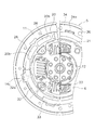
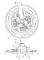
- FIG. 1 is a cross-sectional view of a flywheel torque limiter according to an embodiment of the present invention. Further, FIG. 2 shows a part of a front view of the flywheel torque limiter. Although not shown in FIG. 1, the engine is disposed on the left side, and the transmission is disposed on the right side.
- the torque limiter device 1 is provided between a crankshaft 2 of the engine and a transmission input shaft 3 and is for limiting the torque transmitted from the engine to the transmission.
- the torque limiter device 1 includes a flywheel 5 as a drive member, a clutch disk assembly 6, and a transmission torque limiter 7 including a part of the clutch disk assembly 6.
- the flywheel 5 is a disk-shaped member, and has a hole 5a at its central portion, and has a disk portion 10 from the inner peripheral portion to the radial intermediate portion. In addition, a mass portion 11 is provided on the outer peripheral side of the disc portion 10.
- the hole 5a at the center is fitted to the inlay portion 2a formed on the end face of the crankshaft 2, whereby the radial positioning of the flywheel 5 and the clan shaft 2 is performed.
- a plurality of through holes 5 b aligned in the circumferential direction is formed in the inner peripheral portion of the disc portion 10.
- a plurality of bolts 12 are inserted into the through holes 5 b, and the flywheel 5 can be fixed to the end face of the crankshaft 2 by screwing the plurality of bolts 12 into the screw holes of the crankshaft 2.
- the disc portion 10 has substantially the same axial thickness in all of the radial directions.
- the bolt 12 is a bolt with a hexagonal hole in which a hexagonal hole in which a tightening tool is inserted is formed at the head.
- the mass portion 11 is formed thicker in the axial direction than the disc portion 10.
- a housing portion 14 recessed toward the engine side is formed on the transmission side of the mass portion 11, as shown in an enlarged manner in FIG. 3, a housing portion 14 recessed toward the engine side is formed.
- the housing portion 14 has a radially positioning surface 14a as a cylindrical inner peripheral surface extending in the axial direction on the outer peripheral portion, and a friction connection surface 14b is provided at a portion corresponding to the bottom surface (side wall surface on the engine side) of the housing portion 14 Is formed.
- a plurality of recessed portions 15 that are recessed toward the transmission side are formed at the boundary between the disc portion 10 and the mass portion 11.
- the plurality of recesses 15 are arranged in the circumferential direction, and each of the plurality of recesses 15 is formed in an arc shape.
- a through hole 16 penetrating the recess 15 is formed in the surface on the opposite side corresponding to the recess 15.
- the through hole 16 is formed such that the engine side can not be seen from the transmission side in the axial direction. More specifically, the inner diameter of the friction coupling surface 14 b is smaller than the outermost diameter of the disc portion 10 in the portion where the through hole 16 is formed.
- the clutch disk assembly 6 mainly includes a plurality of torsion springs (dampers) that elastically connect the clutch plate 20 and the retaining plate 21, the spline hub 22, the clutch plate 20 and the retaining plate 21, and the spline hub 22. And the mechanism 23).
- the clutch plate 20 and the retaining plate 21 are both annular members made of sheet metal, for example, and are disposed at predetermined intervals in the axial direction.
- the clutch plate 20 is disposed on the engine side, and the retaining plate 21 is disposed on the transmission side.
- a part of the outer peripheral portion of the retaining plate 21 is bent toward the clutch plate 20 and is further bent toward the inner peripheral side.
- a portion bent to the inner peripheral side of the retaining plate 21 is fixed to the outer peripheral portion of the clutch plate 20 by rivets 24. Thereby, the clutch plate 20 and the retaining plate 21 rotate integrally.
- window holes are formed at equal intervals in the rotational direction on the outer peripheral portion of the clutch plate 20 and the retaining plate 21, and the torsion spring 23 is supported by the window holes.
- holes 20a and 21a are formed in the center of the clutch plate 20 and the retaining plate 21, respectively.
- the diameters of the holes 20a and 21a at the central portions of the two plates 20 and 21 are larger than the mounting pitch circle P (see FIG. 1) of the bolt 12 for fixing the flywheel 5 to the crankshaft 2. Therefore, components other than the spline hub 22 are not disposed on the inner peripheral portion of the clutch disk assembly 6.
- the outer peripheral portion of the clutch plate 20 is formed to extend to the friction coupling surface 14 b of the flywheel 5.
- the outer peripheral surface of the clutch plate 20 is close to the radial positioning surface 14a of the housing portion 14 of the flywheel 5, and the radial positioning surface of the clutch plate 20 is determined by the radial positioning surface 14a.
- a plurality of friction members 26 are disposed on the outer peripheral portion of the clutch plate 20. That is, the outer peripheral portion of the clutch plate 20 functions as a friction coupling plate. More specifically, as shown in FIG. 2, a plurality of arc-shaped holes 20 b are formed in the circumferential direction at the outer peripheral portion of the clutch plate 20. And the friction material 26 formed in circular arc shape is mounted
- the spline hub 22 includes an axially extending cylindrical boss 28 and a disk-shaped hub flange 29 radially extending from the boss 28.
- the boss 28 and the hub flange 29 are integrally formed.
- a spline hole 28 a with which the transmission input shaft 3 engages is formed in the inner peripheral portion of the boss 28.
- the hub flange 29 is formed with a plurality of notches aligned in the rotational direction.
- the torsion spring 23 is accommodated in each of the plurality of notches.
- holes 29 a into which tools for tightening the bolts 12 can be inserted are formed at positions corresponding to the plurality of bolts 12.
- the coaxiality of the spline hole 28a with respect to the inlay portion 2a of the crankshaft 2 is suppressed to 1.0 mm or less, and is configured in the range of 0.2 to 0.3 mm.
- a bush 30 is disposed between the hub flange 29 of the spline hub 22 and the clutch plate 20 and the retaining plate 21 respectively.
- Each bushing 30 is fixed to the clutch plate 20 and the retaining plate 21 so that a hysteresis torque is generated when each bushing 30 rotates relative to the side surface of the hub flange 29.
- the transmission torque limiter 7 has a pressure ring 32 for holding the above-mentioned friction material 26 and the friction material 26 between the friction connection surface 14 b of the flywheel 5 and a cone spring. 33 and a cover member 34 as a support member.
- the pressure ring 32 and the cone spring 33 are housed in the housing portion 14 of the flywheel 5 together with the friction material 26.
- the pressure ring 32 is a ring-shaped plate member, and a plurality of engaging protrusions 32 a protruding radially outward are formed on the outer peripheral portion.
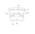
- a plurality of engagement concave portions 14 c are formed on the outer peripheral surface of the housing portion 14 of the flywheel 5, as shown in an enlarged manner in FIG. 4, a plurality of engagement concave portions 14 c are formed.
- the plurality of engagement recesses 14c are formed at equal intervals in the circumferential direction.
- the cone spring 33 is disposed inside the housing portion 14 of the flywheel 5, and the inner peripheral portion presses the pressure ring 32 to the flywheel 5 side.
- the cover member 34 is a ring-shaped plate member, and is fixed to the end face of the mass portion 11 of the flywheel 5 on the transmission side by a plurality of rivets 36. And the outer peripheral part of the cone spring 33 is supported. That is, the inner diameter of the cover member 34 is smaller than the outer diameter of the cone spring 33.
- the cover member 34 and the pressure ring 32 are formed of one ring-shaped plate member.
- a plurality of recessed portions 34a directed radially outward are formed.
- the remaining portion covers member 34
- the recessed portion 34 a functions as a flow path 40 (see FIG. 4) that communicates the outer peripheral portion of the friction material 26 of the clutch plate 20 with the outside of the torque limiter device 1. Therefore, the muddy water or the like that has entered the outer peripheral portion of the clutch plate 20 can be discharged to the outside through the flow path 40.
- the transmittable torque is determined by the biasing force of the cone spring 33, the friction coefficient of the friction material 26, and the effective radius of the friction coupling portion, and a torque exceeding this transmittable torque is input from the engine side As a result, slippage occurs in the frictional connection, and the transmission torque is limited to a predetermined torque.
- the clutch disk assembly 6 and the flywheel 5, which are the main body of the torque limiter device, are positioned in the radial direction by the outer peripheral end face of the clutch plate 20 and the radial positioning surface 14a of the flywheel 5. That is, the flywheel 5 and the spline engagement holes 28 a of the clutch disk assembly 6 are centered in the stage before fixing them to the crankshaft 2.
- the flywheel equipped torque limiter device obtained as described above is mounted on the crankshaft 2. Specifically, the inlay portion 2 a of the crankshaft 2 is fitted into the center hole 5 a of the flywheel 5, and the entire torque limiter device is set to the crankshaft 2. Then, a plurality of bolts 12 are screwed into screw holes formed on the end face of the crankshaft. At this time, the tool is inserted through a hole 29 a formed in the hub flange 29 of the spline hub 22 into a hexagonal hole for a tightening tool formed in the head of the bolt 12, and the bolt 12 is tightened and fixed.
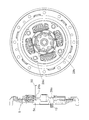
- FIG. 7A the state immediately after assembly is shown in FIG. 7A.
- this state there is a phase between the tool hole 29a of the spline hub 22 and the bolt 12. That is, it is possible to rotate the bolt 12 by the tool through the tool hole 20a.
- the jig 51 has a flange portion 52, a spline shaft 53 formed on one side surface of the flange portion 52, and a nut portion 54 formed on the other side surface of the flange portion 52.
- the flange portion 52 is formed with four holes through which the pin 50 can pass.
- a pin 55 for alignment is fixed on the flange portion 52.
- the alignment pin 55 is insertable into the tool hole 29a and has an outer diameter substantially the same as the inner diameter of the hole 29a.
- the jig 51 as described above is set as shown in FIG. 7C, and the nut portion 54 is rotated using the tool 56. Thereby, the damper disk assembly 6 also rotates. Then, the rotation of the damper disk assembly 6 is stopped in a state where the pin 50 matches the pin hole 5 c of the flywheel 5, and the pin 50 is inserted all the way to the pin hole 5 c of the flywheel 5.
- the flywheel 5 is provided with alignment marks 5d for alignment, and by aligning the phases of the alignment marks 5d and the pin holes 29b, the pins 50 are aligned with the pin holes 5c of the flywheel. You can also judge that.
- the jig 51 is removed in a state where the phases of the pin 50 and the pin hole 5c of the flywheel 5 coincide with each other. This state is shown in FIG. 7E. Since the phase of the clutch disk assembly 6 is fixed by the pin 50, even if the jig 51 is removed, there is no phase shift between the flywheel 5 and the clutch disk assembly 6. In this state, using the tool hole 29a, the bolt 12 is loosened by the tool, and the flywheel torque limiter device is removed from the clamp shaft 2.
- the friction material 26 is attached and fixed to the hole 20 b formed in the clutch plate 20. For this reason, the friction material can be fixed to the plate at low cost compared to the conventional fixing direction by rivets, adhesives or molding. Also, the axial dimension can be shortened.
- the outer peripheral portion of the clutch plate 20 functions as a friction coupling plate. Therefore, the configuration is simplified, and in particular, axial shortening can be realized.
- the flywheel 5 can be centered on the crankshaft 2 by the hole 5 a at the center of the flywheel 5 and the flywheel 5 and the spline holes 28 a of the spline hub 22 are centered, the crankshaft 2 This eliminates the need for the configuration and operation for centering the spline hub 28 and the spline hole 28a of the spline hub 22.
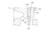
- annular projection 42 is formed on the inner peripheral end of the friction connecting surface 14b of the flywheel 5, and a similar annular projection 43 is formed on the inner peripheral of the pressure ring 32. It is good.
- the two projections 42 and 43 are disposed close to the inner peripheral end of the friction member 26, and are formed to be close to each other on the surface of the clutch plate 20 and to have a predetermined gap.
- the projections may be provided on only one of the members.
- FIG. 6 shows still another embodiment.
- an annular notch 44 is formed at the inner peripheral end of the friction coupling member 14 b of the flywheel 5.
- the wave washer 45 is disposed in the notch 44. That is, a wave washer 45 is provided between the flywheel 5 and the clutch plate 20 on the inner peripheral side of the friction material 26.
- the wave plate 45 biases the clutch plate 20 away from the flywheel 5 (pressure ring 32).
- the member for urging the clutch plate 20 is not limited to the wave washer, and may be an elastic member formed of resin or the like.
- each of the plurality of friction materials may be circular.
- the friction material in the torque limiter device, can be fixed with low cost and a simple configuration.
- Torque limiter device 2 Crankshaft 3 Transmission input shaft 5 Flywheel (drive member) 6 clutch disc assembly 7 transmission torque limiting portion 14b friction coupling surface 20 clutch plate (input side plate) 20b hole 21 retaining plate (input side plate) 22 Spline hub (output side member) 23 torsion spring 26 friction material 32 pressure ring 33 cone spring 34 cover member (supporting member) 42, 43 projection 45 wave spring (biasing member)
Landscapes
- Engineering & Computer Science (AREA)
- General Engineering & Computer Science (AREA)
- Mechanical Engineering (AREA)
- Physics & Mathematics (AREA)
- Acoustics & Sound (AREA)
- Aviation & Aerospace Engineering (AREA)
- Mechanical Operated Clutches (AREA)
- One-Way And Automatic Clutches, And Combinations Of Different Clutches (AREA)
Abstract
Description
図1に本発明の一実施形態としてのフライホイール付きトルクリミッタ装置の断面図を示す。また、図2に、フライホイール付きトルクリミッタ装置の正面図の一部を示す。図1においては、図示していないが、左側にエンジンが配置され、右側にトランスミッションが配置されている。
フライホイール5は、円板状の部材であり、中心部に孔5aを有するとともに、内周部から径方向中間部にかけて円板部10を有している。また、円板部10の外周側には質量部11が設けられている。中心部の孔5aはクランク軸2の端面に形成されたインロウ部2aに嵌合され、これにより、フライホイール5とクラン軸2との径方向の位置決めがなされている。
クラッチディスク組立体6は、主に、クラッチプレート20及びリティーニングプレート21と、スプラインハブ22と、クラッチプレート20及びリティーニングプレート21とスプラインハブ22とを弾性的に連結する複数のトーションスプリング(ダンパー機構)23と、を有している。
伝達トルク制限部7は、図1~図3に示されるように、前述の摩擦材26と、摩擦材26をフライホイール5の摩擦連結面14bとの間で挟持するプレッシャリング32と、コーンスプリング33と、支持部材としてのカバー部材34と、を有している。プレッシャリング32、コーンスプリング33は、摩擦材26とともにフライホイール5の収容部14に収容されている。
以上のようなトルクリミッタ装置を組み立てる場合は、まず、クラッチディスク組立体6を組み立てておく。次に、フライホイール5のボルト装着孔にボルト12を挿入する。そして、フライホイール5の収容部14に、クラッチディスク組立体6、プレッシャリング32、コーンスプリング33の順に配置し、最終的にカバー部材34をリベット36によってフライホイール5に固定する。
以上のようにして組み付けられたトルクリミッタ装置は、以下のような手順で取り外すことができる。なお、装置を取り外すために、図7A以降の図面に示すように、スプラインハブ22のハブフランジ29にはピン用の4つの孔29bが90度間隔で形成されている。また、フライホイール5にも、同様の位置に4つの孔5cが形成されている。図7Aにおいて「ツール用孔」と示しているのは、前述のスプラインハブ22のハブフランジ29に形成された工具挿入用の孔29aである。この図7Aから明らかなように、ピン用孔29bがフライホイール5のピン用孔5cと位相が一致しているときは(円周方向位置が同じときは)、ツール用孔29aとボルト12の位相も一致している。
(1)摩擦材26は、クラッチプレート20に形成された孔20bに装着されて固定されている。このため、リベットや接着剤、あるいはモールド成型による従来の固定方向に比較して、摩擦材を低コストでプレートに固定することができる。また、軸方向の寸法を短縮することができる。
本発明は以上のような実施形態に限定されるものではなく、本発明の範囲を逸脱することなく種々の変形又は修正が可能である。
2 クランク軸
3 トランスミッション入力軸
5 フライホイール(ドライブ部材)
6 クラッチディスク組立体
7 伝達トルク制限部
14b 摩擦連結面
20 クラッチプレート(入力側プレート)
20b 孔
21 リティーニングプレート(入力側プレート)
22 スプラインハブ(出力側部材)
23 トーションスプリング
26 摩擦材
32 プレッシャリング
33 コーンスプリング
34 カバー部材(支持部材)
42,43 突起
45 ウェーブスプリング(付勢部材)
Claims (16)
- エンジン側部材からトランスミッション側の軸に伝達されるトルクを制限するためのトルクリミッタ装置であって、
前記エンジン側部材に連結され摩擦連結面を有するドライブ部材と、
軸方向に貫通する少なくとも1つの孔を有し軸方向に第1厚みを有するプレート本体と、前記摩擦連結用プレートの孔に装着され前記第1厚みより厚い第2厚みを有する摩擦材と、を有する摩擦連結用プレートと、
前記トランスミッション側の軸に係合可能な出力側部材と、
前記摩擦用連結プレートと前記出力側部材とを円周方向に弾性的に連結するダンパー機構と、
前記摩擦材を前記ドライブ部材の摩擦連結面との間で狭持して、前記ドライブ部材から前記トランスミッション側の軸に伝達されるトルクを制限する伝達トルク制限部と、
を備えたトルクリミッタ装置。 - 前記ダンパー機構は、入力側プレートと、前記トランスミッション側の軸に連結される出力側プレートと、前記入力側プレートと前記出力側プレートとの間に配置され前記両プレートを弾性的に連結する複数のトーションスプリングと、を備え、
前記摩擦連結用プレートは前記入力側プレートの外周部である、
請求項1に記載のトルクリミッタ装置。 - 複数の前記摩擦連結用プレートの孔及び摩擦材は円周方向に等角度間隔で配置されている、請求項1に記載のトルクリミッタ装置。
- 複数の前記摩擦材は、対応する前記孔に対して円周方向に隙間のない状態で圧入されている、請求項3に記載のトルクリミッタ装置。
- 前記伝達トルク制限部は、前記摩擦材を前記ドライブ材の摩擦連結面に押圧するプレッシャリングを有し、前記ドライブ材の摩擦連結面及び前記プレッシャリングの少なくともいずれか一方には、前記摩擦材の内周側に配置され、前記摩擦連結用プレートの側面に近づくように突出する突起を有している、請求項1に記載のトルクリミッタ装置。
- 前記ドライブ部材と前記摩擦連結用プレートとの間に設けられ、前記摩擦連結用プレートを前記ドライブ部材から離れる側に付勢する付勢部材をさらに備えた、請求項1に記載のトルクリミッタ装置。
- 前記伝達トルク制限部は、
前記摩擦材を前記ドライブ材の摩擦連結面との間で挟持するプレッシャリングと、
リング状に形成され、内周部が前記プレッシャリングを前記ドライブ部材側に押圧するコーンスプリングと、
前記ドライブ部材に装着され、前記コーンスプリングの外周部を支持する支持部材と、を有している、請求項1に記載のトルクリミッタ装置。 - エンジンのクランク軸からトランスミッション側の軸に伝達されるトルクを制限するためのトルクリミッタ装置であって、
内周部に円周方向に並べて配置され固定用の締結具が挿入される複数の装着孔を有するとともに前記クランク軸端に連結可能であり、摩擦連結面を有する円板状のドライブ部材と、
外周部に摩擦材を有する入力側部材と、
前記トランスミッション側の軸に係合可能な係合部を有する出力側部材と、
前記入力側部材と前記出力側部材とを円周方向に弾性的に連結するダンパー機構と、
前記入力側部材の摩擦材を前記ドライブ部材の摩擦連結面との間で狭持して、前記ドライブ部材から前記トランスミッション側の軸に伝達されるトルクを制限する伝達トルク制限部と、
を備えたトルクリミッタ装置。 - 前記ドライブ部材は前記クランク軸に対する径方向の位置決めを行う位置決め部を有している、請求項8に記載のトルクリミッタ装置。
- 前記出力側部材の係合部は、前記ドライブ部材の位置決め部に対する同軸度が1.0mm以下である、請求項9に記載のトルクリミッタ装置。
- 前記入力側部材及び前記ダンパー機構は、前記ドライブ部材の装着孔の円周ピッチ径よりも径方向外方に配置されており、
前記円周ピッチ径の径方向内方には、前記出力側部材を除いて構成部材は配置されていない、
請求項8に記載のトルクリミッタ装置。 - 前記ドライブ部材の複数の装着孔のそれぞれに挿入された複数の固定締結具をさらに備えた、請求項8に記載のトルクリミッタ装置。
- 前記出力側部材は、中心部に前記スプライン結合部が形成されたボス部と、前記ボス部から径方向外方に延びるフランジ部と、を備え、
前記フランジ部は、前記ドライブ部材の装着孔に挿入された固定締結具を前記クランク軸に締結するための工具が挿入可能な工具挿入用の孔を有している、
請求項12に記載のトルクリミッタ装置。 - エンジンのクランク軸からトランスミッション側の軸に伝達されるトルクを制限するためのトルクリミッタ装置であって、
外周部に摩擦連結面を有し、前記クランク軸端に連結可能な円板状のドライブ部材と、
外周部に摩擦材を有する円板状の入力側部材と、
前記トランスミッション側の軸に係合可能な係合部を有する出力側部材と、
前記入力側部材と前記出力側部材とを円周方向に弾性的に連結するダンパー機構と、
前記入力側部材の摩擦材を前記ドライブ部材の摩擦連結面との間で狭持して、前記ドライブ部材から前記トランスミッション側の軸に伝達されるトルクを制限する伝達トルク制限部と、
を備え、
前記ドライブ部材の外周部には、軸方向に延びて形成された径方向位置決め用の当接部を有し、
前記入力側部材の外周端面が前記ドライブ部材の当接部に当接することにより、前記入力側部材、前記出力側部材、及び前記ダンパー機構が径方向に位置決めされる、
トルクリミッタ装置。 - 前記ドライブ部材は、軸方向に延びて形成された筒状内周面を有し、
前記径方向位置決め用の当接部は前記筒状内周面に形成されている、
請求項14に記載のトルクリミッタ装置。 - 前記筒状内周面には、前記当接部の軸方向トランスミッション側に第1係合部が形成されており、
前記伝達トルク制限部は、
前記摩擦材を前記ドライブ材の摩擦連結面との間で挟持するプレッシャリングと、
リング状に形成され、内周部が前記プレッシャリングを前記ドライブ部材側に押圧するコーンスプリングと、
前記ドライブ部材に装着され、前記コーンスプリングの外周部を支持する支持部材と、を有し、
前記プレッシャリングは、外周部に、前記第1係合部に係合して前記ドライブ部材との相対回転を不能にするための第2係合部を有している、
請求項15に記載のトルクリミッタ装置。
Priority Applications (2)
| Application Number | Priority Date | Filing Date | Title |
|---|---|---|---|
| DE112010002439T DE112010002439T5 (de) | 2009-06-11 | 2010-04-15 | Drehmomentbegrenzer |
| US13/318,454 US8647211B2 (en) | 2009-06-11 | 2010-04-15 | Torque limiter |
Applications Claiming Priority (6)
| Application Number | Priority Date | Filing Date | Title |
|---|---|---|---|
| JP2009140031 | 2009-06-11 | ||
| JP2009-140027 | 2009-06-11 | ||
| JP2009-140028 | 2009-06-11 | ||
| JP2009140027A JP2011027122A (ja) | 2009-06-11 | 2009-06-11 | トルクリミッタ装置 |
| JP2009140028 | 2009-06-11 | ||
| JP2009-140031 | 2009-06-11 |
Publications (1)
| Publication Number | Publication Date |
|---|---|
| WO2010143468A1 true WO2010143468A1 (ja) | 2010-12-16 |
Family
ID=43308728
Family Applications (1)
| Application Number | Title | Priority Date | Filing Date |
|---|---|---|---|
| PCT/JP2010/056774 Ceased WO2010143468A1 (ja) | 2009-06-11 | 2010-04-15 | トルクリミッタ装置 |
Country Status (3)
| Country | Link |
|---|---|
| US (1) | US8647211B2 (ja) |
| DE (1) | DE112010002439T5 (ja) |
| WO (1) | WO2010143468A1 (ja) |
Cited By (2)
| Publication number | Priority date | Publication date | Assignee | Title |
|---|---|---|---|---|
| CN111442062A (zh) * | 2019-01-16 | 2020-07-24 | 株式会社艾科赛迪 | 减振盘组件 |
| JP2021188735A (ja) * | 2020-06-05 | 2021-12-13 | 株式会社エクセディ | 動力伝達装置 |
Families Citing this family (10)
| Publication number | Priority date | Publication date | Assignee | Title |
|---|---|---|---|---|
| JP5724629B2 (ja) * | 2011-05-25 | 2015-05-27 | アイシン精機株式会社 | トルク変動吸収装置 |
| FR3023599B1 (fr) * | 2014-07-11 | 2016-07-01 | Valeo Embrayages | Amortisseur pour dispositif de transmission de couple de vehicule automobile |
| FR3023885B1 (fr) * | 2014-07-18 | 2018-03-02 | Valeo Embrayages | Module de transmission, notamment pour vehicule automobile |
| FR3023886A1 (fr) * | 2014-07-18 | 2016-01-22 | Valeo Embrayages | Module de transmission, notamment pour vehicule automobile |
| US10563723B2 (en) * | 2016-03-16 | 2020-02-18 | Schaeffler Technologies AG & Co. KG | Integrated slip clutch with drive plate for dry damper applications |
| JP7155960B2 (ja) * | 2018-11-30 | 2022-10-19 | 株式会社アイシン | ダンパ |
| JP7267045B2 (ja) * | 2019-03-15 | 2023-05-01 | 株式会社エクセディ | ダンパ装置 |
| JP7289249B2 (ja) * | 2019-10-02 | 2023-06-09 | 株式会社エクセディ | 動力伝達装置 |
| JP7417397B2 (ja) * | 2019-10-02 | 2024-01-18 | 株式会社エクセディ | トルクリミッタ及び動力伝達装置 |
| WO2025040202A1 (de) * | 2023-08-21 | 2025-02-27 | Schaeffler Technologies AG & Co. KG | Bausatz aus schwungrad und dämpfer zur weitergabe von drehmoment von einer verbrennungskraftmaschine zu einem nachgeschalteten getriebe |
Citations (6)
| Publication number | Priority date | Publication date | Assignee | Title |
|---|---|---|---|---|
| JPS63280937A (ja) * | 1987-05-12 | 1988-11-17 | Aisin Chem Co Ltd | 摩擦部材 |
| JPH11325113A (ja) * | 1998-05-15 | 1999-11-26 | Exedy Corp | クラッチカバー組立体 |
| JP2002195290A (ja) * | 2000-10-18 | 2002-07-10 | Os Giken:Kk | 多板クラッチ装置 |
| JP2003194095A (ja) * | 2001-10-17 | 2003-07-09 | Aisin Seiki Co Ltd | トルク変動吸収装置 |
| JP2008280033A (ja) * | 2008-06-16 | 2008-11-20 | Aisin Seiki Co Ltd | ハイブリッド駆動装置用ダンパ |
| JP2008303995A (ja) * | 2007-06-08 | 2008-12-18 | Aisin Seiki Co Ltd | トルク変動吸収装置 |
Family Cites Families (7)
| Publication number | Priority date | Publication date | Assignee | Title |
|---|---|---|---|---|
| US2247690A (en) * | 1939-04-21 | 1941-07-01 | Borg Warner | Friction clutch plate |
| US3610383A (en) * | 1969-11-28 | 1971-10-05 | Frank N Rosteo | Rotary friction construction |
| JPS601497B2 (ja) * | 1978-08-03 | 1985-01-16 | アイシン精機株式会社 | 回転トルク伝達装置 |
| US4401426A (en) * | 1981-03-06 | 1983-08-30 | Power Transmssion Technology, Inc. | Torque limiting clutch |
| US5362276A (en) * | 1992-09-02 | 1994-11-08 | General Motors Corporation | Selective torque clipping mechanism |
| JP3791674B2 (ja) * | 2001-06-26 | 2006-06-28 | アイシン・エィ・ダブリュ株式会社 | トルクリミッタ付ダンパ装置 |
| JP4326414B2 (ja) | 2004-07-01 | 2009-09-09 | 株式会社エクセディ | トルクリミッタ装置の製造方法、及びトルクリミッタ装置の組み付け方法 |
-
2010
- 2010-04-15 DE DE112010002439T patent/DE112010002439T5/de not_active Withdrawn
- 2010-04-15 WO PCT/JP2010/056774 patent/WO2010143468A1/ja not_active Ceased
- 2010-04-15 US US13/318,454 patent/US8647211B2/en active Active
Patent Citations (6)
| Publication number | Priority date | Publication date | Assignee | Title |
|---|---|---|---|---|
| JPS63280937A (ja) * | 1987-05-12 | 1988-11-17 | Aisin Chem Co Ltd | 摩擦部材 |
| JPH11325113A (ja) * | 1998-05-15 | 1999-11-26 | Exedy Corp | クラッチカバー組立体 |
| JP2002195290A (ja) * | 2000-10-18 | 2002-07-10 | Os Giken:Kk | 多板クラッチ装置 |
| JP2003194095A (ja) * | 2001-10-17 | 2003-07-09 | Aisin Seiki Co Ltd | トルク変動吸収装置 |
| JP2008303995A (ja) * | 2007-06-08 | 2008-12-18 | Aisin Seiki Co Ltd | トルク変動吸収装置 |
| JP2008280033A (ja) * | 2008-06-16 | 2008-11-20 | Aisin Seiki Co Ltd | ハイブリッド駆動装置用ダンパ |
Cited By (3)
| Publication number | Priority date | Publication date | Assignee | Title |
|---|---|---|---|---|
| CN111442062A (zh) * | 2019-01-16 | 2020-07-24 | 株式会社艾科赛迪 | 减振盘组件 |
| JP2021188735A (ja) * | 2020-06-05 | 2021-12-13 | 株式会社エクセディ | 動力伝達装置 |
| JP7403391B2 (ja) | 2020-06-05 | 2023-12-22 | 株式会社エクセディ | 動力伝達装置 |
Also Published As
| Publication number | Publication date |
|---|---|
| US20120046114A1 (en) | 2012-02-23 |
| DE112010002439T5 (de) | 2012-10-25 |
| US8647211B2 (en) | 2014-02-11 |
Similar Documents
| Publication | Publication Date | Title |
|---|---|---|
| WO2010143468A1 (ja) | トルクリミッタ装置 | |
| EP1176339A2 (en) | Torque fluctuation absorbing apparatus having structure for reducing misalignment of torque limiter during assembling thereof, and method for assembling the same | |
| JPH11101307A (ja) | ねじれ振動を減衰するための装置 | |
| JP2003194095A (ja) | トルク変動吸収装置 | |
| CN102187117B (zh) | 减振机构 | |
| JP2003013992A (ja) | トルクリミッタ付ダンパ装置 | |
| JP2011027122A (ja) | トルクリミッタ装置 | |
| KR101368033B1 (ko) | 마찰 클러치, 자동차 마찰 클러치 댐퍼용 안내 와셔 및 마찰 클러치 조립 방법 | |
| CN111795113B (zh) | 带扭矩限制器的减振装置 | |
| CN113803404B (zh) | 阻尼装置 | |
| JP5860501B2 (ja) | 動力伝達装置 | |
| US20040211643A1 (en) | Flywheel assembly | |
| JP2004100726A (ja) | ダンパー機構付きトルクリミッタ装置の組み付け方法 | |
| JP5525435B2 (ja) | トルクリミッタ付き軸継手 | |
| JP4326414B2 (ja) | トルクリミッタ装置の製造方法、及びトルクリミッタ装置の組み付け方法 | |
| JP2023179885A (ja) | ダンパ装置 | |
| JP2012167727A (ja) | 動力伝達装置 | |
| KR100272292B1 (ko) | 코일 스프링 어셈블리 및 댐퍼 기계 장치 | |
| KR101542944B1 (ko) | 이중 질량체 플라이휠 | |
| JP2003222191A (ja) | トルク変動吸収装置 | |
| JP5175669B2 (ja) | 捩り振動低減装置 | |
| CN223768030U (zh) | 动力传递装置 | |
| JPH02278053A (ja) | 特に自動車用の緩衝式二重フライホイール | |
| JP2004517285A (ja) | 自動車用の可撓性クラッチフライホイール | |
| CN222863989U (zh) | 限扭减振器 |
Legal Events
| Date | Code | Title | Description |
|---|---|---|---|
| 121 | Ep: the epo has been informed by wipo that ep was designated in this application |
Ref document number: 10785999 Country of ref document: EP Kind code of ref document: A1 |
|
| WWE | Wipo information: entry into national phase |
Ref document number: 13318454 Country of ref document: US |
|
| WWE | Wipo information: entry into national phase |
Ref document number: 112010002439 Country of ref document: DE Ref document number: 1120100024391 Country of ref document: DE |
|
| 122 | Ep: pct application non-entry in european phase |
Ref document number: 10785999 Country of ref document: EP Kind code of ref document: A1 |