WO2010143521A1 - Compresseur de réfrigérant et dispositif pour pompe à chaleur - Google Patents
Compresseur de réfrigérant et dispositif pour pompe à chaleur Download PDFInfo
- Publication number
- WO2010143521A1 WO2010143521A1 PCT/JP2010/058719 JP2010058719W WO2010143521A1 WO 2010143521 A1 WO2010143521 A1 WO 2010143521A1 JP 2010058719 W JP2010058719 W JP 2010058719W WO 2010143521 A1 WO2010143521 A1 WO 2010143521A1
- Authority
- WO
- WIPO (PCT)
- Prior art keywords
- refrigerant
- discharge
- discharge port
- stage
- discharge muffler
- Prior art date
- Legal status (The legal status is an assumption and is not a legal conclusion. Google has not performed a legal analysis and makes no representation as to the accuracy of the status listed.)
- Ceased
Links
Images













Classifications
-
- F—MECHANICAL ENGINEERING; LIGHTING; HEATING; WEAPONS; BLASTING
- F04—POSITIVE - DISPLACEMENT MACHINES FOR LIQUIDS; PUMPS FOR LIQUIDS OR ELASTIC FLUIDS
- F04C—ROTARY-PISTON, OR OSCILLATING-PISTON, POSITIVE-DISPLACEMENT MACHINES FOR LIQUIDS; ROTARY-PISTON, OR OSCILLATING-PISTON, POSITIVE-DISPLACEMENT PUMPS
- F04C23/00—Combinations of two or more pumps, each being of rotary-piston or oscillating-piston type, specially adapted for elastic fluids; Pumping installations specially adapted for elastic fluids; Multi-stage pumps specially adapted for elastic fluids
- F04C23/008—Hermetic pumps
-
- F—MECHANICAL ENGINEERING; LIGHTING; HEATING; WEAPONS; BLASTING
- F04—POSITIVE - DISPLACEMENT MACHINES FOR LIQUIDS; PUMPS FOR LIQUIDS OR ELASTIC FLUIDS
- F04C—ROTARY-PISTON, OR OSCILLATING-PISTON, POSITIVE-DISPLACEMENT MACHINES FOR LIQUIDS; ROTARY-PISTON, OR OSCILLATING-PISTON, POSITIVE-DISPLACEMENT PUMPS
- F04C18/00—Rotary-piston pumps specially adapted for elastic fluids
- F04C18/30—Rotary-piston pumps specially adapted for elastic fluids having the characteristics covered by two or more of groups F04C18/02, F04C18/08, F04C18/22, F04C18/24, F04C18/48, or having the characteristics covered by one of these groups together with some other type of movement between co-operating members
- F04C18/34—Rotary-piston pumps specially adapted for elastic fluids having the characteristics covered by two or more of groups F04C18/02, F04C18/08, F04C18/22, F04C18/24, F04C18/48, or having the characteristics covered by one of these groups together with some other type of movement between co-operating members having the movement defined in group F04C18/08 or F04C18/22 and relative reciprocation between the co-operating members
- F04C18/356—Rotary-piston pumps specially adapted for elastic fluids having the characteristics covered by two or more of groups F04C18/02, F04C18/08, F04C18/22, F04C18/24, F04C18/48, or having the characteristics covered by one of these groups together with some other type of movement between co-operating members having the movement defined in group F04C18/08 or F04C18/22 and relative reciprocation between the co-operating members with vanes reciprocating with respect to the outer member
- F04C18/3562—Rotary-piston pumps specially adapted for elastic fluids having the characteristics covered by two or more of groups F04C18/02, F04C18/08, F04C18/22, F04C18/24, F04C18/48, or having the characteristics covered by one of these groups together with some other type of movement between co-operating members having the movement defined in group F04C18/08 or F04C18/22 and relative reciprocation between the co-operating members with vanes reciprocating with respect to the outer member the inner and outer member being in contact along one line or continuous surfaces substantially parallel to the axis of rotation
- F04C18/3564—Rotary-piston pumps specially adapted for elastic fluids having the characteristics covered by two or more of groups F04C18/02, F04C18/08, F04C18/22, F04C18/24, F04C18/48, or having the characteristics covered by one of these groups together with some other type of movement between co-operating members having the movement defined in group F04C18/08 or F04C18/22 and relative reciprocation between the co-operating members with vanes reciprocating with respect to the outer member the inner and outer member being in contact along one line or continuous surfaces substantially parallel to the axis of rotation the surfaces of the inner and outer member, forming the working space, being surfaces of revolution
-
- F—MECHANICAL ENGINEERING; LIGHTING; HEATING; WEAPONS; BLASTING
- F04—POSITIVE - DISPLACEMENT MACHINES FOR LIQUIDS; PUMPS FOR LIQUIDS OR ELASTIC FLUIDS
- F04C—ROTARY-PISTON, OR OSCILLATING-PISTON, POSITIVE-DISPLACEMENT MACHINES FOR LIQUIDS; ROTARY-PISTON, OR OSCILLATING-PISTON, POSITIVE-DISPLACEMENT PUMPS
- F04C29/00—Component parts, details or accessories of pumps or pumping installations, not provided for in groups F04C18/00 - F04C28/00
- F04C29/0021—Systems for the equilibration of forces acting on the pump
- F04C29/0035—Equalization of pressure pulses
-
- F—MECHANICAL ENGINEERING; LIGHTING; HEATING; WEAPONS; BLASTING
- F04—POSITIVE - DISPLACEMENT MACHINES FOR LIQUIDS; PUMPS FOR LIQUIDS OR ELASTIC FLUIDS
- F04C—ROTARY-PISTON, OR OSCILLATING-PISTON, POSITIVE-DISPLACEMENT MACHINES FOR LIQUIDS; ROTARY-PISTON, OR OSCILLATING-PISTON, POSITIVE-DISPLACEMENT PUMPS
- F04C29/00—Component parts, details or accessories of pumps or pumping installations, not provided for in groups F04C18/00 - F04C28/00
- F04C29/06—Silencing
- F04C29/065—Noise dampening volumes, e.g. muffler chambers
-
- F—MECHANICAL ENGINEERING; LIGHTING; HEATING; WEAPONS; BLASTING
- F04—POSITIVE - DISPLACEMENT MACHINES FOR LIQUIDS; PUMPS FOR LIQUIDS OR ELASTIC FLUIDS
- F04C—ROTARY-PISTON, OR OSCILLATING-PISTON, POSITIVE-DISPLACEMENT MACHINES FOR LIQUIDS; ROTARY-PISTON, OR OSCILLATING-PISTON, POSITIVE-DISPLACEMENT PUMPS
- F04C29/00—Component parts, details or accessories of pumps or pumping installations, not provided for in groups F04C18/00 - F04C28/00
- F04C29/06—Silencing
- F04C29/068—Silencing the silencing means being arranged inside the pump housing
-
- F—MECHANICAL ENGINEERING; LIGHTING; HEATING; WEAPONS; BLASTING
- F04—POSITIVE - DISPLACEMENT MACHINES FOR LIQUIDS; PUMPS FOR LIQUIDS OR ELASTIC FLUIDS
- F04C—ROTARY-PISTON, OR OSCILLATING-PISTON, POSITIVE-DISPLACEMENT MACHINES FOR LIQUIDS; ROTARY-PISTON, OR OSCILLATING-PISTON, POSITIVE-DISPLACEMENT PUMPS
- F04C29/00—Component parts, details or accessories of pumps or pumping installations, not provided for in groups F04C18/00 - F04C28/00
- F04C29/12—Arrangements for admission or discharge of the working fluid, e.g. constructional features of the inlet or outlet
-
- F—MECHANICAL ENGINEERING; LIGHTING; HEATING; WEAPONS; BLASTING
- F04—POSITIVE - DISPLACEMENT MACHINES FOR LIQUIDS; PUMPS FOR LIQUIDS OR ELASTIC FLUIDS
- F04C—ROTARY-PISTON, OR OSCILLATING-PISTON, POSITIVE-DISPLACEMENT MACHINES FOR LIQUIDS; ROTARY-PISTON, OR OSCILLATING-PISTON, POSITIVE-DISPLACEMENT PUMPS
- F04C2240/00—Components
- F04C2240/30—Casings or housings
-
- F—MECHANICAL ENGINEERING; LIGHTING; HEATING; WEAPONS; BLASTING
- F04—POSITIVE - DISPLACEMENT MACHINES FOR LIQUIDS; PUMPS FOR LIQUIDS OR ELASTIC FLUIDS
- F04C—ROTARY-PISTON, OR OSCILLATING-PISTON, POSITIVE-DISPLACEMENT MACHINES FOR LIQUIDS; ROTARY-PISTON, OR OSCILLATING-PISTON, POSITIVE-DISPLACEMENT PUMPS
- F04C2270/00—Control; Monitoring or safety arrangements
- F04C2270/12—Vibration
-
- F—MECHANICAL ENGINEERING; LIGHTING; HEATING; WEAPONS; BLASTING
- F04—POSITIVE - DISPLACEMENT MACHINES FOR LIQUIDS; PUMPS FOR LIQUIDS OR ELASTIC FLUIDS
- F04C—ROTARY-PISTON, OR OSCILLATING-PISTON, POSITIVE-DISPLACEMENT MACHINES FOR LIQUIDS; ROTARY-PISTON, OR OSCILLATING-PISTON, POSITIVE-DISPLACEMENT PUMPS
- F04C2270/00—Control; Monitoring or safety arrangements
- F04C2270/13—Noise
-
- F—MECHANICAL ENGINEERING; LIGHTING; HEATING; WEAPONS; BLASTING
- F04—POSITIVE - DISPLACEMENT MACHINES FOR LIQUIDS; PUMPS FOR LIQUIDS OR ELASTIC FLUIDS
- F04C—ROTARY-PISTON, OR OSCILLATING-PISTON, POSITIVE-DISPLACEMENT MACHINES FOR LIQUIDS; ROTARY-PISTON, OR OSCILLATING-PISTON, POSITIVE-DISPLACEMENT PUMPS
- F04C2270/00—Control; Monitoring or safety arrangements
- F04C2270/14—Pulsations
-
- F—MECHANICAL ENGINEERING; LIGHTING; HEATING; WEAPONS; BLASTING
- F04—POSITIVE - DISPLACEMENT MACHINES FOR LIQUIDS; PUMPS FOR LIQUIDS OR ELASTIC FLUIDS
- F04C—ROTARY-PISTON, OR OSCILLATING-PISTON, POSITIVE-DISPLACEMENT MACHINES FOR LIQUIDS; ROTARY-PISTON, OR OSCILLATING-PISTON, POSITIVE-DISPLACEMENT PUMPS
- F04C2270/00—Control; Monitoring or safety arrangements
- F04C2270/20—Flow
-
- F—MECHANICAL ENGINEERING; LIGHTING; HEATING; WEAPONS; BLASTING
- F04—POSITIVE - DISPLACEMENT MACHINES FOR LIQUIDS; PUMPS FOR LIQUIDS OR ELASTIC FLUIDS
- F04C—ROTARY-PISTON, OR OSCILLATING-PISTON, POSITIVE-DISPLACEMENT MACHINES FOR LIQUIDS; ROTARY-PISTON, OR OSCILLATING-PISTON, POSITIVE-DISPLACEMENT PUMPS
- F04C23/00—Combinations of two or more pumps, each being of rotary-piston or oscillating-piston type, specially adapted for elastic fluids; Pumping installations specially adapted for elastic fluids; Multi-stage pumps specially adapted for elastic fluids
- F04C23/001—Combinations of two or more pumps, each being of rotary-piston or oscillating-piston type, specially adapted for elastic fluids; Pumping installations specially adapted for elastic fluids; Multi-stage pumps specially adapted for elastic fluids of similar working principle
Definitions
- the present invention relates to a refrigerant compressor and a heat pump device using the refrigerant compressor, for example.
- a vapor compression refrigeration cycle using a rotary compressor is used in a refrigeration air conditioner such as a refrigerator, an air conditioner, or a heat pump type hot water heater. From the viewpoint of preventing global warming, it is necessary to save energy and improve efficiency of the vapor compression refrigeration cycle.
- a refrigeration air conditioner such as a refrigerator, an air conditioner, or a heat pump type hot water heater.
- There is an injection cycle using a two-stage compressor as a vapor compression refrigeration cycle that achieves energy saving and efficiency. In order to make the injection cycle using a two-stage compressor more widespread, cost reduction and further efficiency are required.
- the refrigerant compressed by the compression unit is discharged from the cylinder chamber of the compression unit through the discharge port to the discharge muffler space.
- the refrigerant discharged to the discharge muffler space reduces pressure pulsation in the discharge muffler space, and then flows from the communication port through the communication channel to the internal space of the sealed shell.
- excessive pressure in the cylinder chamber is caused by the pressure loss that occurs between the discharge from the cylinder chamber and the flow into the internal space of the sealed shell, and the pressure pulsation due to the phase change between the volume change in the cylinder chamber and the valve opening and closing. Compression (overshoot) loss occurs.
- the refrigerant compressed in the low-stage compression section is discharged into the low-stage discharge muffler space, and the refrigerant discharged into the low-stage discharge muffler space reduces pressure pulsation in the low-stage discharge muffler space. After that, it flows into the high-stage compression section through the intermediate connection flow path. That is, in the two-stage compressor, generally, the low-stage compression section and the high-stage compression section are connected in series by an intermediate connection section such as a low-stage discharge muffler space or an intermediate connection flow path. At this time, in the conventional two-stage compressor, a specific loss cause such as the following (1), (2), and (3) is added, and a large intermediate pressure pulsation loss occurs.
- the intermediate pressure pulsation loss corresponds to the sum of the overcompression (overshoot) loss that occurs in the cylinder chamber of the low-stage compression portion and the underexpansion (undershoot) loss that occurs in the cylinder suction portion of the high-stage compression portion.
- a pressure pulsation is generated in the intermediate connecting portion due to a difference between the timing at which the low-stage compression unit discharges the refrigerant and the timing at which the high-stage compression unit sucks the refrigerant, and this influence causes pressure pulsation in the cylinder chamber. Loss increases.
- connection channel is thin and long, or because a flow in which the refrigerant shrinks or expands by a connection port (entrance / exit) between the intermediate connection channel and a wide space, or the intermediate connection channel Since the flow direction changes three-dimensionally when passing through, pressure loss increases.
- Patent Document 1 describes a two-stage compressor in which the volume of the intermediate connecting portion is set larger than the excluded volume of the compression chamber of the high-stage compression portion. In this two-stage compressor, the pressure pulsation is reduced by the buffering action of the intermediate coupling portion having a large volume.
- Patent Document 2 describes a two-stage compressor provided with an intermediate container in which an internal space is divided into two spaces by a partition member.
- One of the two spaces is a main stream side space communicating from the refrigerant discharge port of the low-stage compression unit to the refrigerant suction port of the high-stage compression unit.
- the other space is an anti-mainstream space that is not directly connected to the refrigerant discharge port of the low-stage compression unit and the refrigerant suction port of the high-stage compression unit.
- the partition member that partitions the main flow side space and the anti-main flow side space is provided with a refrigerant flow path, and the refrigerant enters and exits the main flow side space and the anti-main flow side space via the refrigerant flow path.
- the anti-mainstream side space functions as a buffer container and reduces the pressure pulsation of the intermediate container.
- FIG. 1-5 of Patent Document 3 shows a cross-sectional view of a conventional general low-stage discharge muffler space.
- the low-stage discharge muffler space is formed in a donut shape in which the inner diameter side is surrounded by a bearing portion, the outer diameter side is surrounded by a cylindrical outer peripheral side wall, and the lower part is surrounded by a container bottom lid. Further, in this low-stage discharge muffler space, bolts for fixing the bearing portion support member and the lid of the cylindrical container and bolt fixing portions are arranged at equal intervals.
- Patent Document 4 describes a compressor that discharges refrigerant compressed by a compression unit from a discharge port provided with a discharge valve and a stopper to a discharge muffler space.
- a restraining member is provided between the stopper provided at the discharge port and the top plate of the discharge muffler space to prevent the refrigerant from entering the back side of the stopper.
- Patent Document 5 describes a compressor in which a discharge valve that opens and closes a discharge port is attached to a bearing portion of a compression mechanism portion, and a valve cover (discharge muffler container) is attached around the bearing portion. is there.
- the silencing space component surrounding the discharge valve is formed integrally with the stopper of the discharge valve to form the silencing space.
- An object having a blunt side surface and a sharp side surface with respect to a flow has a characteristic that a resistance coefficient greatly varies depending on a posture with respect to the flow.
- a resistance coefficient (C D ) obtained by making a resistance (D) acting on a three-dimensional object non-dimensional by a dynamic pressure of the flow and a projection area S onto a plane perpendicular to the flow of the object. It is shown as follows.
- Resistance coefficient (C D) resistance (D) ⁇ the dynamic pressure ( ⁇ u 2/2) ⁇ projected area (S)
- the resistance coefficient when the convex surface side of the hemisphere faces the upstream flow direction is 0.42, whereas the convex surface side faces the downstream flow direction.
- the resistance coefficient in this case is 1.17, which is about 3 times.
- the resistance coefficient when the convex surface side of the hemispherical shell faces the upstream flow direction is 0.38, whereas the resistance coefficient when the convex surface side faces the downstream flow direction is 1.42, which is about four times as large. Has been.
- the resistance coefficient when the convex surface side of the semi-cylindrical shell having a two-dimensional object shape faces the upstream direction is about 1.2
- the resistance coefficient when the convex surface side faces the downstream direction of the flow is 2.3. It is described that it is about 2 times.
- the hemispherical shell has a shape in which the plane side of the hemisphere is recessed inward
- the semicylindrical shell has a shape in which the plane side of the half cylinder is recessed inward.
- resistance (D) acts in the flow path of width h
- pressure loss ( ⁇ P) generated in the flow path it can be expressed as follows.
- Resistance (D) ⁇ h ⁇ ⁇ P From the above, it can be considered that the pressure loss ( ⁇ P) generated in the flow path is substantially proportional to the resistance (D) of the object placed in the flow path.
- the amplitude of the pressure pulsation at the intermediate connecting portion is reduced by providing a large buffer container at the intermediate connecting portion.
- the refrigerant flows while expanding and contracting in the intermediate connecting portion, so that the pressure loss increases.
- the followability of the refrigerant flowing through the intermediate connecting portion is deteriorated, and a phase delay occurs. For this reason, even if the amplitude of the pressure pulsation at the intermediate connection portion decreases, the pressure loss at the intermediate connection portion increases on the contrary. Even when the volume of the low-stage discharge muffler space is adjusted instead of the buffer container, the same state is obtained.
- the restraining member does not necessarily serve to regulate the flow from the discharge port to the communication port, which is important for the flow in the discharge muffler space, and the flow in the entire discharge muffler space. Therefore, the effect of reducing the pressure loss and improving the compressor efficiency is small.
- An object of the present invention is to reduce the pressure pulsation amplitude in the discharge muffler space where the refrigerant compressed by the compression unit is discharged and to reduce the pressure loss, and to improve the compressor efficiency. To do.
- the refrigerant compressor according to the present invention is, for example, A compressor that is driven by rotation of a drive shaft provided through the central portion and sucks and compresses the refrigerant into the cylinder chamber; A refrigerant that is compressed in the cylinder chamber is discharged from a discharge port provided in the compression unit, and a discharge muffler space that flows out from a communication port provided in a predetermined position to another space makes a circle around the drive shaft.
- a discharge muffler formed as a space of In the circular circulation flow path in the reverse direction of the two-way circulation flow paths in the forward direction and the reverse direction in which the flow direction around the axis is different from the discharge port toward the communication port in the annular discharge muffler space formed by the discharge muffler.
- a discharge port rear surface guide provided at a position closer to the discharge port than the communication port and preventing the refrigerant discharged from the discharge port from flowing in the reverse direction; The discharge port rear surface guide prevents the refrigerant from flowing in the reverse direction, whereby the refrigerant circulates in the annular discharge muffler space in the forward direction.
- the refrigerant discharged from the discharge port is prevented from flowing in the reverse direction by the discharge port rear surface guide. Therefore, the refrigerant discharged from the discharge port easily circulates in the positive direction through the annular discharge muffler space. Generation of pressure pulsation can be suppressed by circulating the refrigerant in a certain direction in the annular discharge muffler space. Further, since the refrigerant circulates in a certain direction in the annular discharge muffler space, the refrigerant flow is less likely to be disturbed, and the pressure loss is reduced. Therefore, in the multistage compressor according to the present invention, the compressor efficiency is improved.
- FIG. 2 is a cross-sectional view showing the overall configuration of the two-stage compressor according to the first embodiment.
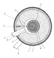
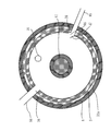
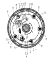
- FIG. 2 is a B-B ′ cross-sectional view of the two-stage compressor of FIG. 1 according to the first embodiment.
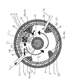
- FIG. 2 is a cross-sectional view taken along the line A-A ′ of the two-stage compressor in FIG. 1 according to the first embodiment.
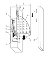
- FIG. 3 is a perspective view of a discharge port rear surface guide 41 and a discharge port guide guide 42 according to the first embodiment. Explanatory drawing of arrangement
- FIG. 3 is a diagram illustrating an example of a minimum configuration of the two-stage compressor according to the first embodiment.
- FIG. 3 is a diagram illustrating an example of a minimum configuration of the two-stage compressor according to the first embodiment.
- FIG. 17 is a C-C ′ sectional view of the two-stage compressor in FIG.
- FIG. 16 shows a lower discharge muffler space 131 according to the tenth embodiment.
- Schematic shows the structure of the heat pump type heating hot-water supply system 100 which concerns on Embodiment 11.
- Embodiment 1 a two-stage compressor (two-stage rotary compressor) having two compression sections (compression mechanisms) including a low-stage compression section and a high-stage compression section will be described as an example of a multistage compressor.
- the multistage compressor may be a compressor having three or more compression units (compression mechanisms).
- arrows indicate the flow of the refrigerant.
- FIG. 1 is a cross-sectional view showing the overall configuration of the two-stage compressor according to the first embodiment.
- the two-stage compressor according to the first embodiment includes a low-stage compression section 10, a high-stage compression section 20, a low-stage discharge muffler 30, a high-stage discharge muffler 50, a lower support member 60, and an upper support inside the hermetic shell 8.
- a member 70, a lubricating oil storage unit 3, an intermediate partition plate 5, a drive shaft 6, and a motor unit 9 are provided.
- the low stage discharge muffler 30, the lower support member 60, the low stage compression part 10, the intermediate partition plate 5, the high stage compression part 20, the upper support member 70, the high stage discharge muffler 50, and the motor part 9 are stacked in order from the lower side in the axial direction of the drive shaft 6.
- the lubricating oil storage unit 3 is provided on the lowest side in the axial direction of the drive shaft 6.
- the low stage compression unit 10 and the high stage compression unit 20 include cylinders 11 and 21, respectively.
- the low-stage compression unit 10 and the high-stage compression unit 20 include cylinder chambers 11 a and 21 a inside the cylinders 11 and 21, rotary pistons 12 and 22, and vanes 14 and 24, respectively.
- the cylinders 11 and 21 are provided with cylinder suction ports 15 and 25.
- the low-stage compression unit 10 is stacked such that the cylinder 11 is sandwiched between the lower support member 60 and the intermediate partition plate 5.
- the high-stage compression unit 20 is stacked such that the cylinder 21 is sandwiched between the upper support member 70 and the intermediate partition plate 5.
- the low-stage discharge muffler 30 includes a container 32 having a container outer peripheral side wall 32a and a container bottom lid 32b, and a low-stage discharge muffler seal portion 33.
- the low-stage discharge muffler 30 forms a low-stage discharge muffler space 31 surrounded by the container 32 and the lower support member 60.
- the container 32 and the lower support member 60 are sealed with a low-stage discharge muffler seal portion 33 so that the intermediate pressure refrigerant that has entered the low-stage discharge muffler space 31 does not leak.
- the container outer peripheral side wall 32 a is provided with a communication port 34 that communicates with the high-stage compression unit 20 via the intermediate connection pipe 84.
- the injection piping 85 is attached to the container outer peripheral side wall 32a. The injection refrigerant flowing through the injection pipe 85 is injected from the injection inlet 86 into the low-stage discharge muffler space 31.
- the high-stage discharge muffler 50 includes a container 52.
- the high-stage discharge muffler 50 forms a high-stage discharge muffler space 51 surrounded by the container 52 and the upper support member 70.
- the container 52 is provided with a communication port 54 that communicates with the space inside the sealed shell 8.
- the lower support member 60 includes a lower bearing portion 61 and a discharge port side surface 62.
- the lower bearing portion 61 is formed in a cylindrical shape and supports the drive shaft 6.
- the discharge port side surface 62 forms the low-stage discharge muffler space 31 and supports the low-stage compression unit 10. Further, the discharge port side surface 62 communicates with a cylinder chamber (compression space) 11 a formed by the cylinder 11 of the low-stage compression unit 10 and a low-stage discharge muffler space 31 formed by the low-stage discharge muffler 30.
- a discharge valve concave installation portion 18 provided with the discharge port 16 is formed.
- a discharge valve 17 (open / close valve) that opens and closes the discharge port 16 is attached to the discharge valve recessed portion 18.
- the upper support member 70 includes an upper bearing portion 71 and a discharge port side surface 72.
- the upper bearing portion 71 is formed in a cylindrical shape and supports the drive shaft 6.
- the discharge port side surface 72 forms the high-stage discharge muffler space 51 and supports the high-stage compression unit 20.
- the discharge port side surface 72 communicates with a cylinder chamber (compression space) 11 a formed by the cylinder 21 of the high-stage compression unit 20 and a high-stage discharge muffler space 51 formed by the high-stage discharge muffler 50.
- a discharge valve concave installation portion 28 provided with the discharge port 26 is formed.
- a discharge valve 27 (open / close valve) that opens and closes the discharge port 26 is attached to the discharge valve recessed portion 28.
- the two-stage compressor according to the first embodiment includes the compressor suction pipe 1, the suction muffler connection pipe 4, the suction muffler 7, and the intermediate connection pipe 84 outside the sealed shell 8.
- the suction muffler 7 sucks refrigerant from an external refrigerant circuit via the compressor suction pipe 1.
- the suction muffler 7 separates the sucked refrigerant into a gas refrigerant and a liquid refrigerant.
- the separated gas refrigerant is sucked from the suction muffler connecting pipe 4 to the low-stage compression unit 10.
- the intermediate connection pipe 84 forms an intermediate connection flow path that connects the communication port 34 of the low stage discharge muffler 30 and the cylinder chamber 21a of the high stage compression unit 20.
- the low-pressure refrigerant flows into the suction muffler 7 ((2) in FIG. 1) via the compressor suction pipe 1 ((1) in FIG. 1).
- the refrigerant flowing into the suction muffler 7 is separated into a gas refrigerant and a liquid refrigerant in the suction muffler 7.
- the gas refrigerant passes through the suction muffler connecting pipe 4 ((3) in FIG. 1) and is sucked into the cylinder chamber 11a of the low-stage compression unit 10 (((1) in FIG. 1)). 4)).
- the refrigerant sucked into the cylinder chamber 11a is compressed to an intermediate pressure by the low stage compression unit 10.
- the refrigerant compressed to the intermediate pressure is discharged from the discharge port 16 to the low-stage discharge muffler space 31 ((5) in FIG. 1).
- the refrigerant discharged into the low-stage discharge muffler space 31 passes through the intermediate connection flow path from the communication port 34 ((6) in FIG. 1) and is sucked into the cylinder 21 of the high-stage compression unit 20 (((1) in FIG. 1). 7)).
- the refrigerant sucked into the cylinder 21 is compressed to a high pressure by the high stage compression unit 20.
- the refrigerant compressed to a high pressure is discharged from the discharge port 26 to the high-stage discharge muffler space 51 ((8) in FIG. 1). Then, the refrigerant discharged to the high-stage discharge muffler space 51 is discharged from the communication port 54 to the internal space of the sealed shell 8 ((9) in FIG. 1). The refrigerant discharged into the internal space of the sealed shell 8 passes through the gap of the motor unit 9 above the compression unit, and then is discharged to the external refrigerant circuit through the compressor discharge pipe 2 fixed to the sealed shell 8. ((10) in FIG. 1). Further, when the injection operation is performed, the injection refrigerant flowing through the injection pipe 85 ((11) in FIG.
- the injection refrigerant ((12) in FIG. 1) and the refrigerant discharged from the discharge port 16 to the low-stage discharge muffler space 31 ((5) in FIG. 1) are mixed. .
- the mixed refrigerant is sucked into the cylinder 21 of the high-stage compression unit 20 ((6) and (7) in FIG. 1), compressed to a high pressure, and discharged to the outside ((8 in FIG. 1). (9) (10)).
- the refrigerant and the lubricating oil are separated while the high-pressure refrigerant passes through the internal space of the sealed shell 8.
- the separated lubricating oil is stored in the lubricating oil storage section 3 at the bottom of the hermetic shell 8, pumped up by a rotary pump attached to the lower portion of the drive shaft 6, and supplied to the sliding section and the sealing section of each compression section.
- the refrigerant compressed to a high pressure by the high stage compression unit 20 and discharged to the high stage discharge muffler space 51 is discharged to the internal space of the sealed shell 8. Therefore, the pressure in the sealed shell 8 is equal to the discharge pressure of the high-stage compression unit 20. Therefore, the compressor shown in FIG. 1 is a high-pressure shell type.
- FIG. 2 is a cross-sectional view of the two-stage compressor of FIG. 1 according to Embodiment 1 taken along the line BB ′.
- the motor unit 9 rotates the drive shaft 6 around the axis 6d to drive the compression units 10 and 20. Due to the rotation of the drive shaft 6, the rotary pistons 12 and 22 in the cylinder chambers 11a and 21a are eccentrically rotated counterclockwise by the low-stage compression unit 10 and the high-stage compression unit 20, respectively. As shown in FIG.
- the position in the eccentric direction where the gap between the rotary piston 12 and the inner wall of the cylinder 11 is minimized is from the rotation reference phase ⁇ 0 to the cylinder suction port phase ⁇ S1 .
- the rotary piston 12 rotates and compresses the refrigerant so as to move in the order of the phase ⁇ d1 of the discharge port.
- the rotation reference phase is the position of the vane 14 that partitions the cylinder chamber 11a into the compression side and the suction side. That is, the rotary piston 12 rotates in the counterclockwise direction from the rotation reference phase ⁇ 0 through the phase ⁇ S1 of the cylinder suction port 15 to the phase ⁇ d1 of the discharge port 16 to compress the refrigerant.
- the eccentric direction position moves counterclockwise from the rotation reference phase ⁇ 0 through the phase ⁇ S2 of the cylinder suction port 25 to the phase ⁇ d2 of the discharge port 26.
- the rotary piston 22 rotates and compresses the refrigerant.
- the low-stage discharge muffler space 31 will be described.
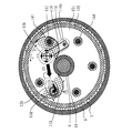
- 3 is a cross-sectional view taken along the line AA ′ of the two-stage compressor of FIG. 1 according to the first embodiment.
- the low-stage discharge muffler space 31 is surrounded by the container 32 having the container outer peripheral side wall 32a and the container bottom lid 32b, and the lower support member 60 having the lower bearing portion 61 and the discharge port side surface 62. It is formed. Further, the container 32 and the lower support member 60 are sealed by the seal portion 33 and separated from the high-pressure lubricating oil storage portion 3 in the sealed shell 8. As shown in FIG.
- the low-stage discharge muffler space 31 has an inner peripheral wall formed by a lower bearing portion 61 and an outer peripheral wall formed by a container outer peripheral side wall 32a in a cross section perpendicular to the axial direction of the drive shaft 6. Thus, it is formed in a ring shape (doughnut shape) that goes around the drive shaft 6. That is, the low-stage discharge muffler space 31 is formed in an annular shape (loop shape) that goes around the drive shaft 6.
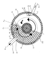
- the refrigerant compressed by the low-stage compressor 10 is discharged from the discharge port 16 ((1) in FIG. 3) and the injection refrigerant is injected from the injection inlet 86 into the low-stage discharge muffler space 31 (FIG. 3 (5)).
- These refrigerants circulate (i) in the annular low-stage discharge muffler space 31 in the forward direction (direction A in FIG. 3) ((3) in FIG. 3), and (ii) from the communication port 34 to the intermediate connecting pipe It flows into the high stage compression part 20 via 84 ((7) (8) of FIG. 3).
- the low-stage discharge muffler space 31 includes a discharge port rear surface guide 41, a discharge port guide guide 42, A rectifying guide 43, guide guides 44a, 44b, 44c and 44d, a rectifying guide 45, an inlet guide 47, and a diversion guide 48 are provided.
- FIG. 4 is an explanatory diagram of the discharge port rear surface guide 41 and the discharge port guide 42 according to the first embodiment.
- the discharge port rear surface guide 41 is opposite to the forward direction (direction A in FIGS. 3 and 4) around the discharge port 16, which is different in the direction around the axis from the discharge port 16 to the communication port 34 in the annular discharge muffler space. It is provided on the flow path side (back side) in the opposite direction of the flow paths in the two directions (B direction in FIGS. 3 and 4).
- the flow path length from the discharge port 16 to the communication port 34 is longer in the reverse flow path than in the forward flow path.
- the discharge port guide 42 is provided so as to cover the discharge port 16 with a space between the discharge port 16 and the discharge port 16.
- the discharge port guide 42 has openings on the side where the discharge port rear surface guide 41 is provided and on the opposite side (communication port side).
- the refrigerant is discharged radially from the discharge port 16 ((1) in FIGS. 3 and 4). However, the flow of the refrigerant in the direction in which the discharge port rear surface guide 41 is provided (direction B in FIGS. 3 and 4) is hindered by the discharge port rear surface guide 41. Therefore, the refrigerant discharged from the discharge port 16 flows in a direction different from the direction in which the discharge port rear surface guide 41 is provided.
- the refrigerant since the flow of the refrigerant is hindered by the discharge port guide 42, the refrigerant is rectified and flows in a direction opposite to the direction in which the discharge port rear surface guide 41 is provided (forward direction, direction A in FIGS. 3 and 4) ( (2) in FIGS. As described above, the refrigerant discharged from the discharge port 16 by the discharge port rear surface guide 41 and the discharge port guide 42 flows in the positive direction. Since the low-stage discharge muffler space 31 is formed in an annular shape, the refrigerant circulates in the positive direction ((3) in FIG. 3).
- the discharge port rear surface guide 41 prevents the refrigerant discharged from the discharge port 16 from flowing in the reverse direction and does not block the flow of the refrigerant circulating in the forward direction.
- the discharge port 16 side (forward direction side) of the discharge port rear surface guide 41 is formed in a concave shape, and the reverse side (reverse direction side) of the discharge port 16 is formed in a convex shape. That is, the discharge port 16 side (forward direction side) of the discharge port rear surface guide 41 is made dull and the reverse side (reverse direction side) of the discharge port 16 is made sharp.
- the shape of the cross section perpendicular to the axial direction of the discharge port rear surface guide 41 is U-shaped or V-shaped so that the discharge port 16 side is concave and the opposite side is convex.
- the resistance coefficient in the reverse direction is approximately twice as large as that in the positive direction in the flow path in the two directions. It works to circulate the refrigerant in the positive direction.
- a metal plate provided with a large number of holes such as punching metal and a metal net is used, so that the refrigerant discharged from the discharge port 16 can be used.
- the discharge valve concave installation portion 18 provided with the discharge port 16 is formed on the discharge port side surface 62 of the lower support member 60.
- a discharge valve 17 formed of a thin plate-like elastic body such as a leaf spring is attached to the discharge valve concave installation portion 18.
- a stopper 19 for adjusting (limiting) the lift amount (deflection size) of the discharge valve is attached so as to cover the discharge valve 17.
- One end side of the discharge valve 17 and the stopper 19 is fixed to the discharge valve concave installation portion 18 with a bolt 19b.
- the discharge valve 17 bends to open and close the discharge port 16, and refrigerant is discharged from the discharge port 16 to the low-stage discharge muffler. Discharge into the space 31. That is, the discharge valve mechanism that opens the discharge port 16 is a reed valve system.
- the stopper 19 is fixed at one end side to the back side of the discharge port 16 and is inclined so as to gradually move away from the discharge port 16 toward the communication port 34 side of the discharge port 16. Provided.
- the stopper 19 has a narrow radial width d and is inclined at a gentle angle close to parallel with the discharge port side surface 62 provided with the discharge port 16. Therefore, the stopper 19 hardly prevents the refrigerant discharged from the discharge port 16 from flowing in the reverse direction (B direction in FIGS. 3 and 4).
- the discharge port rear surface guide 41 is provided at an angle close to perpendicular to the discharge port side surface 62.
- the radial width D1 of the discharge port rear guide 41 and the radial width D2 of the discharge port guide 42 are the diameter of the discharge port 16, the radial width of the discharge valve 17, and the radial width d of the stopper 19. Greater than.
- the flow path projection area S1 of the discharge port rear surface guide 41 is that the discharge port rear surface guide 41 passes through a predetermined plane passing through the axis 6d by rotating the discharge port rear surface guide 41 about the axis 6d as a rotation axis. It is the area of the figure obtained by plotting the locus.
- the projected flow area s of the stopper is a figure obtained by plotting the locus of the stopper 19 passing through a predetermined plane passing through the axis 6d by rotating the stopper 19 about the axis 6d as a rotation axis. It is an area.
- the flow path projection area of a certain object is a figure obtained by plotting a trajectory through which the object passes through a predetermined plane passing through the axis 6d by rotating the object about the axis 6d as a rotation axis. It is an area.
- the discharge port rear guide 41 and the discharge port guide 42 prevent the refrigerant discharged from the discharge port 16 from flowing in the reverse direction and promote the flow in the forward direction in a range wider than the stopper 19. Therefore, by providing the discharge port back guide 41 and the discharge port guide 42, the refrigerant discharged from the discharge port 16 can be circulated in the forward direction.
- the inlet guide 47 will be described with reference to FIG.
- the inlet guide 47 has a forward direction (A direction in FIG. 3) and a reverse direction (B direction in FIG. 3) in which the direction around the axis from the injection inlet 86 to the communication port 34 is different around the injection inlet 86.
- the inlet guide 47 is provided so as to protrude from the flow path side in the opposite direction so as to cover the injection inlet 86 and protrude into the low-stage discharge muffler space 31.
- the refrigerant circulates in the positive direction ((3) in FIG. 3).
- the wall 36 on the positive direction side of the injection inlet 86 is tapered so as to be substantially parallel to the inlet guide 47 so that the refrigerant is easily deflected to flow in the positive direction. Is attached.
- the rectifying guide 43 and the rectifying guide 45 will be described with reference to FIG.
- the rectifying guide 43 and the rectifying guide 45 are provided on the container outer peripheral side wall 32a that forms the outer periphery of the low-stage discharge muffler space 31 so as to be inclined and protrude toward the positive direction where the refrigerant circulates by the discharge port rear surface guide 41 and the like.
- the straightening guide 43 has a forward direction (A direction in FIG. 3) and a reverse direction (B direction in FIG. 3) in which the direction around the axis from the discharge port 16 to the communication port 34 is different around the communication port 34. It is provided on the opposite flow path side of the two flow paths.
- the rectifying guide 45 is provided at a substantially intermediate position between the rectifying guide 43 and the inlet guide 47 in the positive direction in which the refrigerant circulates.
- the rectifying guide 43 and the rectifying guide 45 prevent the refrigerant from flowing in the direction opposite to the circulation direction.
- a refrigerant flow in a direction opposite to the circulation direction is likely to occur at a timing when the amount of refrigerant sucked by the high-stage compressor 20 exceeds the amount of refrigerant discharged by the low-stage compressor 10.
- the flow in the reverse direction can be prevented by the flow straightening guide 43 and the flow straightening guide 45 and the inlet guide 47 described above.
- the guides 44a, 44b, 44c, and 44d are refrigerants between the container outer peripheral side wall 32a that forms the outer periphery of the low-stage discharge muffler space 31 and the lower bearing portion 61 that forms the inner periphery of the low-stage discharge muffler space 31. It is provided in a shape along the circulation direction.
- the guiding guides 44a, 44b, 44c, and 44d are provided so that a plate bent into an airfoil shape follows the refrigerant circulation direction.
- the guide 44 a is provided on the flow path side in the positive direction of the discharge port 16 and outside the discharge port 16 in the radial direction of the low-stage discharge muffler space 31. Further, the guide 44 b is provided on the flow path side in the positive direction of the discharge port 16 and inside the discharge port 16 in the radial direction of the low-stage discharge muffler space 31. In particular, the guides 44a and 44b guide the refrigerant discharged from the discharge port 16 and flowing in the forward direction in the circulation direction.
- the guide 44c is provided at a substantially intermediate position between the rectifying guide 43 and the rectifying guide 45 in the refrigerant circulation direction.
- the guide 44c guides in the circulation direction so that the flow of the refrigerant circulating in the low-stage discharge muffler space 31 is not disturbed.
- the guide 44d is provided at a substantially intermediate position between the inlet guide 47 and the guide 44a in the refrigerant circulation direction. In particular, the guide 44d guides the forward flow of the refrigerant formed by the inlet guide 47 in the circulation direction ((6) in FIG. 3).
- the diversion guide 48 will be described with reference to FIG.
- the diversion guide 48 is provided between the position of the communication port 34 and the center position of the low-stage discharge muffler space 31 (axial center 6d of the drive shaft 6) in a cross section perpendicular to the axial direction of the drive shaft 6.
- the diversion guide 48 is formed in a rod shape (columnar shape) extending in the axial direction of the drive shaft 6 (see FIG. 1).
- the diversion guide 48 promotes the diversion of the refrigerant in the circulation direction in which the refrigerant circulates ((3) in FIG. 3) and the outflow direction in which the refrigerant flows out from the communication port 34 ((7) in FIG. 3).
- the wall surface 37 on the opposite side of the communication port 34 is tapered so that the refrigerant branched in the outflow direction can easily flow into the intermediate connection pipe 84 from the communication port 34.
- the refrigerant discharged radially from the discharge port 16 to the low-stage discharge muffler space 31 is guided by the discharge port rear surface guide 41 and the discharge port guide 42 and flows in the positive direction ( (2) in FIGS.
- the refrigerant discharged from the discharge port 16 is urged by the rectifying guide 43, the guiding guides 44a, 44b, 44c, 44d, and the rectifying guide 45, and circulates in the low-stage discharge muffler space 31 ((3) in FIG. 3).
- the refrigerant ((4) in FIG. 3) injected from the injection inlet 86 is guided by the inlet guide 47 and flows in the forward direction ((5) in FIG. 3).
- the refrigerant injected from the injection inlet 86 is urged by the rectifying guide 43, the guiding guides 44a, 44b, 44c, 44d, and the rectifying guide 45, and circulates in the low-stage discharge muffler space 31 ((3 in FIG. 3). )).
- the refrigerant discharged from the discharge port 16, the refrigerant injected from the injection inlet 86, and the refrigerant circulating in the low-stage discharge muffler space 31 are near the outlet of the injection inlet 86, near the guide guide 44d, and discharged. In the vicinity of the outlet rear surface guide 41 or the like, they are mixed and mixed ((6) in FIG. 3).
- the refrigerant flowing in the low-stage discharge muffler space 31 is divided into the circulation direction and the outflow direction by the diversion guide 48.
- the refrigerant flowing in the circulation direction circulates in the low-stage discharge muffler space 31 ((3) in FIG. 3). It flows into the section 20 ((7) (8) in FIG. 3).
- FIG. 5 is an explanatory diagram of the arrangement of the discharge port 16 and the communication port 34 according to the first embodiment and the inclination of the injection port guide 47 according to the first embodiment.
- the AA ′ cross-sectional view of the two-stage compressor of FIG. 1 according to Embodiment 1 is simply shown with a part of the configuration omitted.
- a circle 38 indicated by a broken line is centered on the center position (axial center 6 d of the drive shaft 6) of the low-stage discharge muffler space 31 in the cross section perpendicular to the axial direction of the drive shaft 6, and the center of the discharge port 16.
- the tangent line 93 is a tangent line of the circle 38 at the center position 91 of the discharge port 16, and is a tangent line drawn to the flow path side in the positive direction from the discharge port 16 to the communication port 34.
- a line 94 is a line connecting the center position 91 of the discharge port 16 and the center position 92 of the communication port 34 in a cross section perpendicular to the axial direction of the drive shaft 6.
- the discharge port 16 and the communication port 34 are arranged at a position where an angle 95 formed by the tangent line 93 and the line 94 is 90 degrees or less. That is, when the position of the discharge port 16 is the position shown in FIG. 5, the position of the communication port 34 is arranged in the shaded portion 35 in FIG.
- the center position of the discharge port and the center position of the communication port correspond to the center of gravity positions of the openings provided in the containers 32 and 42, the lower support member 60, and the upper support member 70 constituting the discharge muffler. If the opening is a two-dimensional shape, it is a two-dimensional centroid position, and if the opening is a three-dimensional shape, it is a three-dimensional centroid position.
- Disposing the discharge port 16 and the communication port 34 in this way uses the force for sucking the refrigerant by the high-stage compression unit 20, that is, the force for sucking the refrigerant into the communication port 34 as the force for flowing the refrigerant in the positive direction. It is to do.
- the ideal flow direction of the circulating refrigerant at the center position 91 of the discharge port 16 is the direction indicated by the tangent line 93. If the angle 95 formed by this ideal flow direction and the line 94 is 90 degrees or less, the force for sucking the refrigerant into the communication port 34 can be used as the force for flowing the refrigerant in the ideal flow direction. . On the other hand, if the angle 95 is greater than 90 degrees, the force for sucking the refrigerant into the communication port 34 acts as a force that prevents the refrigerant from flowing in an ideal flow direction.
- the discharge port 16 and the communication port 34 may be disposed at a position where the angle 95 formed by the tangent line 93 and the line 94 is 30 degrees or less, or the angle 95 formed by the tangent line 93 and the line 94 is 0 degree.
- the discharge port 16 and the communication port 34 may be arranged at a position where Further, the communication port 34 may be arranged in the range of ⁇ 0 to ( ⁇ d1 ⁇ 180 degrees). That is, the communication port 34 may be arranged in a region excluding the region between ⁇ d1 and ⁇ 0 in the hatched portion 35 in FIG.
- a circle 39 indicated by a broken line is centered on the center position (axial center 6 d of the drive shaft 6) of the low-stage discharge muffler space 31 in the cross section perpendicular to the axial direction of the drive shaft 6.
- the tangent line 98 is a tangent line of the circle 39 at the center position 96 of the injection inlet 86, and is a tangent line drawn toward the flow path in the positive direction from the injection inlet 86 to the communication port 34.
- a line 97 is a line substantially parallel to the inclination of the injection port guide 47 passing through the center position 91 of the discharge port 16 in a cross section perpendicular to the axial direction of the drive shaft 6.
- the inlet guide 47 is tilted so that the angle 99 formed by the tangent line 98 and the line 97 is 90 degrees or less. That is, the inlet guide 47 is provided to be inclined so as to gradually move away from the injection inlet 86 from the reverse direction side to the forward direction side of the injection inlet 86.
- the reason why the inlet guide 47 is arranged in this way is to use the force at which the refrigerant is injected from the injection inlet 86 as the force for flowing the refrigerant in the positive direction.
- the ideal flow direction of the circulating refrigerant at the center position 96 of the injection inlet 86 is the direction indicated by the tangent line 98. If the angle 99 formed by this ideal flow direction and the line 97 is 90 degrees or less, use the force at which the refrigerant is injected from the injection inlet 86 as the force for flowing the refrigerant in the ideal flow direction. Can do. On the other hand, if the angle 99 is greater than 90 degrees, the force that the refrigerant is injected from the injection inlet 86 acts as a force that prevents the refrigerant from flowing in the ideal flow direction.
- the injection pipe 85 is generally connected so as to be 90 degrees with respect to the closed shell 8 and the container outer peripheral side wall 32a. That is, the injection pipe 85 is generally connected to the tangent line 98 at 90 degrees. Even in this case, the force at which the refrigerant is injected from the injection inlet 86 can be used as the force for flowing the refrigerant in the ideal flow direction. However, by providing the inlet guide 47 and making the angle 99 smaller than 90 degrees, the force through which the refrigerant is injected from the injection inlet 86 is used more effectively as the force for flowing the refrigerant in the ideal flow direction. It becomes possible to do.
- the low-stage discharge muffler space 31 is formed in an annular shape, and the refrigerant is circulated in a certain direction.
- the pressure pulsation is not a pressure loss but a rotational kinetic energy. This has the effect of being replaced and adjusted, and the occurrence of pressure pulsation can be suppressed.
- the multistage compressor according to the present invention by encouraging the refrigerant circulation direction in the annular discharge muffler space to be a constant direction, it is difficult to disturb the refrigerant flow and increase in pressure loss can be prevented. Therefore, in the two-stage compressor according to Embodiment 1, the compressor efficiency is improved.
- the discharge port rear surface guide 41, the discharge port guide guide 42, the flow guide 43, the guide guides 44a, 44b, 44c, 44d, the flow guide 45, the injection port It is desirable to provide the guide 47, the taper of the wall surface 37 on the opposite direction side of the communication port 34, the taper of the wall surface 36 of the injection injection port 86 on the forward direction side, and all the guides for the diversion guide 48.
- the guide 47 it is possible to suppress the occurrence of pressure pulsation to some extent and to prevent an increase in pressure loss.
- the inlet guide 47 by providing at least the inlet guide 47, the occurrence of pressure pulsation can be suppressed to some extent, and an increase in pressure loss can be prevented.
- Embodiment 2 FIG. In the second embodiment, experimental results for the two-stage compressor described in the first embodiment will be described.
- Experiment 1 is an experiment on the relationship between the specific compressor efficiency and the operating frequency when the refrigerant is not injected.
- FIG. 8 is a diagram showing the relationship (result of Experiment 1) between the specific compressor efficiency and the operating frequency of the two-stage compressor according to Embodiment 1 when the refrigerant is not injected.
- the specific compressor efficiency is based on the compressor efficiency when the operation frequency of the conventional general method 1 (target 1) is 60 Hz.
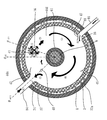
- the target 3 is a two-stage compressor that includes only the discharge port rear surface guide 41 and the discharge port guide 42 and does not include other guides. That is, the target 3 is a two-stage compressor in which the inside of the low-stage discharge muffler space 31 is configured as shown in FIG. 6 and the discharge port guide 42 is further provided.
- the target 4 is a two-stage compressor provided with all the guides described in the first embodiment. That is, the object 4 is a two-stage compressor having the configuration shown in FIG. 3 in the low-stage discharge muffler space 31.
- Experiment 2 is an experiment on the relationship between the specific compressor efficiency and the specific injection refrigerant amount when the refrigerant is injected.
- FIG. 9 is a diagram showing a relationship (result of Experiment 2) between the specific compressor efficiency of the two-stage compressor according to Embodiment 1 and the specific injection refrigerant amount when the refrigerant is injected.
- the specific compressor efficiency is based on the compressor efficiency when the specific injection refrigerant amount of the conventional general method 2 (target 5) is 0%.
- the specific injection refrigerant amount was based on the refrigerant amount sucked into the low-stage compression unit 10. That is, the specific injection refrigerant amount indicates how much refrigerant is injected with respect to the refrigerant amount sucked into the low-stage compression unit 10.
- the compressor efficiency was compared for the following four types of low-stage discharge muffler configurations. Note that the volume of any low-stage discharge muffler space 31 was 85 cc.
- the target 5 is a two-stage compressor that does not provide a guide in the low-stage discharge muffler space 31 and is provided with an injection inlet 86 that injects an injection refrigerant in the middle of the intermediate connecting pipe.
- Subject 6 Conventional invention method 2
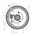
- the target 6 is a two-stage compressor in which the low-stage discharge muffler space 31 has the shape shown in FIG.
- An injection inlet 86 for injecting an injection refrigerant into the low-stage discharge muffler space 31 is provided.
- a two-stage compressor provided.
- the object 7 is a two-stage compressor provided with only the inlet guide 47 and not provided with other guides. That is, the object 7 is a two-stage compressor having the configuration shown in FIG. 7 in the low-stage discharge muffler space 31.
- the target 8 is a two-stage compressor provided with all the guides described in the first embodiment. That is, the target 8 is a two-stage compressor having the configuration shown in FIG. 3 in the low-stage discharge muffler space 31.
- the two-stage compressor according to Embodiment 1 can reduce pressure fluctuations and pressure losses that occur in the low-stage discharge muffler over a wide operating speed range.
- the two-stage compressor according to Embodiment 1 can similarly reduce pressure fluctuations and pressure losses that occur in the low-stage discharge muffler even when the refrigerant is injected. Therefore, the compressor efficiency is improved.
- Embodiment 3 In the third embodiment, an integrated discharge port back guide 41 in which the discharge port back guide 41 and the discharge port guide 42 are integrally formed will be described.
- FIG. 10 is an explanatory diagram of the integrated discharge port rear surface guide 41 according to the third embodiment.
- the integrated discharge port rear surface guide 41 shown in FIG. 10 is provided so as to cover the discharge port 16 from the back surface side.
- the integrated discharge port rear surface guide 41 shown in FIG. 10 is provided with an opening on the flow path side in the positive direction from the discharge port 16 to the communication port 34. That is, the integrated discharge port rear surface guide 41 shown in FIG. 10 is provided so as to cover the rear surface side and both side surfaces of the discharge port 16.
- the concave surface side is directed in the forward direction and the upstream direction
- the convex surface side is directed in the forward direction and directed in the downstream direction.
- the resistance coefficient generated in the discharge port rear surface guide 41 is larger in the reverse direction than in the positive direction.
- the resistance coefficient generated in the discharge port rear surface guide 41 is about five times larger in the reverse direction than in the forward direction.
- FIG. 11 is an explanatory diagram of another example of the integrated discharge port rear surface guide 41 according to the third embodiment.
- the integrated discharge port rear surface guide 41 shown in FIG. 11 is formed in a plate shape, and is inclined from the back surface side to the container bottom lid 32b so as to cover the discharge port 16.
- the two-stage compressor according to the first embodiment is provided even with the two-stage compressor provided with the integrated discharge port rear surface guide 41 shown in FIGS. The same effect as the machine can be obtained.
- Embodiment 4 FIG.
- the low-stage discharge muffler space 31 in which a part of the guide is formed by the bolt fixing portion provided in the low-stage discharge muffler 30 will be described.
- FIG. 12 is a diagram illustrating a low-stage discharge muffler space 31 according to the fourth embodiment.
- FIG. 13 is an explanatory diagram of the discharge port rear surface guide 41 according to the fourth embodiment. Only the portions of the low-stage discharge muffler space 31 shown in FIG. 12 that are different from the low-stage discharge muffler space 31 shown in FIG. 3 will be described.
- bolt fixing portions 65a, 65b, 65c, 65d are formed on the container outer peripheral side wall 32a.
- the bolt fixing portions 65a, 65b, 65c, and 65d are formed such that the container outer peripheral side wall 32a protrudes toward the low-stage discharge muffler space 31 side.
- Four fastening bolts 64 are inserted into the bolt fixing portions 65a, 65b, 65c, 65d, and the low-stage discharge muffler 30 and the lower support member 60 are fastened.
- the protruding bolt fixing portions 65a, 65b, 65c, and 65d have a predetermined shape and are arranged at predetermined positions, whereby the guide described in the first embodiment is provided. Part is formed.
- the discharge port rear surface guide 41 is formed by a bolt fixing portion 65 a that is disposed on the opposite side of the discharge valve concave installation portion 18.
- the bolt fixing portion 65a is formed so as to surround the back side of the discharge port 16 (discharge valve concave installation portion 18).
- the bolt fixing portion 65a closes about half of the channel width (the radial width in FIG.
- the rectifying guide 43 is formed by a bolt fixing portion 65 b disposed on the positive direction side of the communication port 34.
- the bolt fixing part 65b closes the flow path having a narrower width than the bolt fixing part 65a, and the flow path width of the part where the bolt fixing part 65b is formed is w2 wider than w1. Therefore, the flow passage area of the portion where the bolt fixing portion 65a is formed is smaller than the flow passage area of the portion where the bolt fixing portion 65b is formed.
- the rectifying guide 45 is formed by a bolt fixing portion 65c. Further, the inlet guide 47 is formed by the bolt fixing portion 65d.
- the bolt fixing portions 65b, 65c, and 65d are formed such that a portion where the container outer peripheral side wall 32a protrudes into the low-stage discharge muffler space 31 is inclined toward the positive direction side. That is, the bolt fixing portions 65b, 65c, and 65d are arranged so as to guide the annular flow from the discharge port 16 to the positive direction side.
- the discharge port guide 42 provided so as to cover the discharge port 16 is fixed to the bolt fixing portion 65a by a fastening bolt 64.
- the bolt fixing portion 65a is formed only in the range of the height H1 on the discharge port side surface 62 side. Therefore, a flow path having a height H2 is secured between the bolt fixing portion 65a and the container bottom lid 32b. For this reason, even in the portion where the bolt fixing portion 65a is provided, the coolant can circulate and flow in an annular shape by the flow path having the height H2.
- the use of a metal plate having a large number of holes as a material for forming the discharge port guide 42 has an effect of attenuating the pressure pulsation of the refrigerant discharged from the discharge port 16.
- the two-stage compressor has a part of the guide formed by the bolt fixing portion, the same effect as that of the two-stage compressor according to the first embodiment can be obtained.
- Embodiment 5 In the two-stage compressor described in the first embodiment, a part of the intermediate connection flow path that connects the low-stage compression unit 10 and the high-stage compression unit 20 is formed by the intermediate connection pipe 84 that passes outside the sealed shell 8. .
- the intermediate connection pipe 84 that passes outside the sealed shell 8.
- a two-stage compressor in which an intermediate connection channel passes through the inside of the hermetic shell 8 will be described.
- FIG. 14 is a diagram illustrating a low-stage discharge muffler space 31 according to the fifth embodiment.
- the low-stage discharge muffler space 31 shown in FIG. 14 will be described only in parts different from the low-stage discharge muffler space 31 shown in FIG.
- the communication port 34 is provided on the discharge port side surface 62 of the lower support member 60.
- an intermediate connection channel that connects the communication port 34 of the low-stage compression unit 10 and the cylinder suction port 25 of the high-stage compression unit 20 passes through the low-stage cylinder 11 and the intermediate partition plate 5 and is formed inside the sealed shell 8. Is done.
- a rectifying guide 43 with a container outer peripheral side wall 32 a protruding is provided so as to surround the positive direction side of the communication port 34.
- the intermediate connection flow path is a two-stage compressor passing through the inside of the hermetic shell 8
- the same effect as the two-stage compressor according to the first embodiment can be obtained.
- the injection inlet 86 is provided nearer to the back side of the discharge port 16 than in the low stage discharge muffler space 31 shown in FIG. 3. Therefore, the injection port guide 47 also serves as the discharge port rear surface guide 41. That is, in the low-stage discharge muffler space 31 shown in FIG. 14, the inlet guide 47 urges the refrigerant injected from the injection inlet 86 to flow in the forward direction, and the refrigerant discharged from the discharge port 16 is in the reverse direction. Block the flow to.
- the two-stage compressor according to the first embodiment is used. The same effect as a compressor can be obtained.
- Embodiment 6 In the first embodiment, in order to make the low-stage discharge muffler space 31 into a refrigerant circulation flow path that communicates in a loop shape, the discharge port rear surface guide 41 partially partitions the flow path on the opposite direction side to prevent the flow of the refrigerant. Shaped. In Embodiment 6, it is set as the shape which partitions off the whole flow path of the reverse direction side by the discharge outlet back surface guide 41, and blocks a flow. That is, in the sixth embodiment, the low-stage discharge muffler space 31 apparently forms a refrigerant circulation channel that communicates with the C type.
- FIG. 15 is a diagram illustrating a low-stage discharge muffler space 31 according to the sixth embodiment.
- the discharge port rear surface guide 41 protrudes from the rear surface side of the discharge port 16 and surrounds the upper surface side of the discharge port 16 and the side surface side of the discharge port 16, and is an integrated type that also functions as the discharge port guide 42. This is a discharge port rear surface guide 41.
- the discharge port rear surface guide 41 partitions the entire annular flow path on the rear surface side of the discharge port 16.
- the discharge port rear surface guide 41 is formed of, for example, a metal plate provided with a large number of holes, such as a punching metal or a metal mesh, the refrigerant can flow through the holes.
- the discharge port rear surface guide 41 is formed of a metal plate provided with a large number of holes, the effect of attenuating the pressure pulsation of the refrigerant discharged from the discharge port 16, the refrigerant discharged from the discharge port 16, and The effect of mixing and rectifying the refrigerant circulating in the low-stage discharge muffler space 31 and the refrigerant injected from the injection inlet 86 is obtained.
- the pressure loss that occurs due to passing through the discharge port rear surface guide 41 when the refrigerant is circulated annularly through the low-stage discharge muffler space 31 in a certain direction Since it becomes larger than that of the first embodiment, a compressor loss correspondingly occurs.
- the pressure loss is reduced as compared with the conventional example.
- the effect of attenuating the pressure pulsation of the refrigerant is obtained by allowing the refrigerant to flow through the low-stage discharge muffler space 31 for one round and using a metal plate provided with a large number of holes. For this reason, the two-stage compressor according to the sixth embodiment can improve the compressor efficiency in accordance with the two-stage compressor according to the first embodiment.
- FIG. FIG. 16 is a diagram illustrating a low-stage discharge muffler space 31 according to the seventh embodiment.
- the discharge port rear surface guide 41 is provided on the reverse flow channel side having a long flow channel length among the two flow channels from the discharge port 16 to the communication port 34. Therefore, the angle at which the refrigerant traveling from the discharge port 16 to the communication port 34 circulates from ⁇ d1 to ⁇ out1 is within 180 degrees.
- the seventh embodiment is different from the first embodiment in that the discharge port rear surface guide 41 is provided on the positive flow channel side with a short distance among the two flow channels from the discharge port 16 to the communication port 34.
- the angle at which the refrigerant from the discharge port 16 toward the communication port 34 circulates from ⁇ d1 to ⁇ out1 is 180 degrees or more.
- the refrigerant discharged radially from the discharge port 16 ((1) in FIG. 16) is prevented from flowing in the forward direction by the curved discharge port rear surface guide 41 that covers the rear side of the discharge port, and the reverse direction ( (Clockwise direction) ((2), (3) in FIG. 16). Further, when the refrigerant ((4) in FIG.
- the angle at which the refrigerant traveling from the discharge port 16 to the communication port 34 circulates from ⁇ d1 to ⁇ out1 is 180 degrees or more. Since the pressure loss caused by the flow toward the port 34 is larger than that in the first embodiment, the compressor loss increases accordingly.
- the low-stage discharge muffler space 31 is formed in an annular shape, and the refrigerant is circulated in a certain direction.
- the pressure pulsation is not caused by pressure loss by circulating the refrigerant in the annular discharge muffler space between the timing at which the low-stage compression unit discharges the refrigerant and the timing at which the high-stage compression unit sucks the refrigerant. It has the effect of adjusting by replacing with rotational kinetic energy. Therefore, the occurrence of pressure pulsation can be suppressed. Furthermore, in the two-stage compressor according to the seventh embodiment, by encouraging the refrigerant circulation direction in the annular low-stage discharge muffler space 31 to be a constant direction, the refrigerant flow is less likely to be disturbed, and the pressure loss is increased. Can be prevented. Therefore, the two-stage compressor according to the seventh embodiment can improve the compressor efficiency in accordance with the two-stage compressor according to the first embodiment.
- the rotary piston type two-stage compressor has been described.
- any compression format may be used as long as it is a two-stage compressor having a muffler space in which a high-stage compression section and a low-stage compression section are intermediately connected.
- the same effect can be obtained even with various two-stage compressors such as a swing piston type and a sliding vane type.
- the high-pressure shell type two-stage compressor in which the pressure in the hermetic shell 8 is equal to the pressure in the high-stage compression unit 20 has been described.
- the same effect can be obtained regardless of whether the intermediate pressure shell type or the low pressure shell type two-stage compressor.
- the two-stage compressor in which the low-stage compressor 10 is disposed below the high-stage compressor 20 and the refrigerant is discharged downward into the low-stage discharge muffler space 31 has been described.
- similar effects can be obtained even with a two-stage compressor in which the arrangement of the low-stage compressor 10, the high-stage compressor 20, and the low-stage discharge muffler 30 and the rotation direction of the drive shaft 6 are different.
- the same effect can be obtained even in a two-stage compressor in which the low-stage compression unit 10 is disposed above the high-stage compression unit 20 and discharges the refrigerant upward into the low-stage discharge muffler space 31.
- the same effect can be obtained even when the vertical two-stage compressor is placed horizontally.
- the discharge valve mechanism that opens the discharge port 16 is a reed valve system that opens and closes by the elasticity of a thin plate-like valve and the pressure difference between the low-stage compression unit 10 and the low-stage discharge muffler space 31. It was assumed and explained. However, other types of discharge valve mechanisms may be used. For example, a check valve that opens and closes the discharge port 16 using a pressure difference between the low-stage compression unit 10 and the low-stage discharge muffler space 31 such as a poppet valve type used in an intake / exhaust valve of a four-stroke engine may be used. .
- the configuration in which the injection inlet 86 is provided in the low stage discharge muffler 30 and the refrigerant is injected into the low stage discharge muffler space 31 is used.
- the compressor efficiency improvement effect similar to the experimental result of FIG. 9 can also be obtained in the case where the injection pipe 85 is connected to the intermediate connecting pipe provided outside the hermetic shell 8 and the refrigerant is injected.
- the two-stage compressor according to the above embodiment includes a low-stage compression section, a high-stage compression section, a drive shaft and a motor for driving the two compression mechanisms, and a low-stage discharge muffler in a sealed shell.
- the stored low-pressure refrigerant is sucked into the low-stage cylinder chamber 11a of the low-stage compression section and compressed to an intermediate pressure, and then the low-stage discharge valve is opened and the inside of the low-stage discharge muffler is opened from the low-stage discharge port.
- the intermediate pressure refrigerant After being discharged into the space, it is led from the communication port to the intermediate connection flow path, the intermediate pressure refrigerant is sucked from the intermediate communication flow path into the high-stage cylinder chamber 21a of the high-stage compression section, compressed to a high pressure, and then sealed.
- the internal space of the low-stage discharge muffler forms a refrigerant circulation channel that communicates in a loop, and the low-stage discharge port and the communication port are disposed as a junction and a diversion port of the refrigerant circulation channel, The low-stage discharge port so that the phase difference between the ideal flow tangent direction of the refrigerant circulation flow path and the shortest path direction from the low-stage discharge port to the communication port coincides within 90 degrees at the stage discharge point.
- a flow guide for preventing a backflow is provided on the back side, the top side, or the bottom side.
- the two-stage compressor includes a low-stage compression section, a high-stage compression section, a drive shaft and motor for driving the two compression mechanisms, and a low-stage discharge muffler in a sealed shell. And a closed shell other than these is filled with refrigerant and lubricating oil, and low-pressure refrigerant is sucked into the low-stage cylinder chamber 11a of the low-stage compression section and compressed to an intermediate pressure,
- the low-stage discharge valve opens and discharges from the low-stage discharge port to the internal space of the low-stage discharge muffler.
- the low-stage discharge muffler internal space forms a loop-shaped refrigerant circulation passage, and the low-stage discharge outlet refrigerant, injection serves as a confluence and a diversion outlet of the refrigerant circulation passage.
- the injection port and the communication port are arranged, and the injection port is arranged such that an ideal flow tangent direction of the refrigerant circulation channel and a phase difference between the injection refrigerant injection directions coincide within 90 degrees at the injection inlet point.
- a flow guide is formed in the vicinity, and the refrigerant discharged from the low-stage discharge port is mixed with the refrigerant in the low-stage discharge muffler space.
- the two-stage compressor according to the above-described embodiment is characterized in that a flow guide for arranging the merged flow and the divided flow in the vicinity of the merged port and the divided port of the refrigerant circulation channel is arranged.
- the flow guide is characterized by using a metal plate material, punching metal, or wire mesh in which a large number of openings are distributed.
- the flow guide for adjusting the merged flow and the divided flow in the vicinity of the merged port and the divided port of the refrigerant circulation channel is characterized by a round bar shape.
- Embodiment 8 FIG.
- the structure of the low-stage discharge muffler space 31 of the two-stage compressor in which two compression units are connected in series has been described.
- a structure of a lower discharge muffler of a single-stage twin compressor in which two compression units are connected in parallel will be described.
- a large pressure pulsation is generated in the intermediate connecting portion due to a difference between the timing at which the low-stage compression portion discharges the refrigerant and the timing at which the high-stage compression portion sucks the refrigerant. Therefore, reducing the intermediate pressure pulsation loss is very important in improving the compressor efficiency.
- the large pressure pulsation unlike the intermediate connection part of the two stage compressor does not occur.
- FIG. 17 is a cross-sectional view showing an overall configuration of a single-stage twin compressor according to Embodiment 8. Only parts different from the two-stage compressor shown in FIG. 1 will be described.
- the single-stage twin compressor according to the eighth embodiment includes the lower compression unit 110, the upper compression unit 120, the lower discharge muffler 130, and the upper discharge muffler 150 inside the hermetic shell 8 according to the second embodiment.
- the low-stage compressor 10, the high-stage compressor 20, the low-stage discharge muffler 30, and the high-stage discharge muffler 50 provided in the stage compressor are provided.
- the structures of the lower compression unit 110, the upper compression unit 120, the lower discharge muffler 130, and the upper discharge muffler 150 are the low-stage compression unit 10, the high-stage compression unit 20, the low-stage discharge muffler 30, and the high-stage discharge muffler 50. Since the structure is substantially the same as that of FIG. Since the lower discharge muffler space 131 is almost the same pressure as the internal pressure of the sealed shell 8, unlike the low-stage discharge muffler 30 of the first embodiment, a seal portion for sealing the lower discharge muffler is unnecessary.
- the discharge port side surface 62 is formed with a communication port 134 through which the refrigerant flowing into the lower discharge muffler space 131 flows out.
- a lower discharge flow path 138 connected to the communication port 134 is formed through the discharge port side surface 62, the lower compression portion 110, the intermediate partition plate 5, the upper compression portion 120, and the discharge port side surface 72.
- the lower discharge flow path 138 is a flow path that guides the refrigerant flowing out from the communication port 134 of the lower discharge muffler 130 to the space in the sealed shell 8 between the upper compression section 120 and the motor section 9.
- the low-pressure refrigerant flows into the suction muffler 7 ((2) in FIG. 17) via the compressor suction pipe 1 ((1) in FIG. 17).
- the refrigerant flowing into the suction muffler 7 is separated into a gas refrigerant and a liquid refrigerant in the suction muffler 7.
- the gas refrigerant branches into the suction muffler connection pipe 4a side and the suction muffler connection pipe 4b side in the suction muffler connection pipe 4, and is sucked into the cylinder 111 of the lower compression part 110 and the cylinder chamber 121a of the upper compression part 120 ( (3) and (6) of FIG.
- the refrigerant sucked into the cylinder chamber 111a of the lower compression unit 110 and compressed to the discharge pressure by the lower compression unit 110 is discharged from the discharge port 116 to the lower discharge muffler space 131 ((4) in FIG. 17). .
- the refrigerant discharged into the lower discharge muffler space 131 is guided from the communication port 134 through the lower discharge flow path 138 to the space between the upper compression unit 120 and the motor unit 9 ((5) in FIG. 17). ).
- the refrigerant sucked into the cylinder chamber 121a of the upper compression unit 120 and compressed to the discharge pressure by the upper compression unit 120 is discharged from the discharge port 126 to the upper discharge muffler space 151 ((7) in FIG. 17).
- the refrigerant discharged to the upper discharge muffler space 151 is guided from the communication port 154 to a space between the motor portion 9 in the sealed shell 8 ((8) in FIG. 17).
- the refrigerant ((8) in FIG. 17) guided to the space between the two merges.
- the merged refrigerant passes through the gap of the motor unit 9 above the compression unit, and is then discharged to the external refrigerant circuit through the compressor discharge pipe 2 fixed to the hermetic shell 8 ((9 in FIG. 17). )).
- the lower discharge muffler 130 will be described.
- 18 is a cross-sectional view taken along the line CC ′ of the single-stage twin compressor of FIG. 17 according to the eighth embodiment.
- the lower discharge muffler space 131 is surrounded by a discharge muffler container 132 and a lower support member 60 having a lower bearing portion 61 and a discharge port side surface 62, and is connected to the drive shaft 6 in an annular shape. 131 is formed.
- the lower discharge muffler space 131 has an inner peripheral wall formed by the lower bearing portion 61 and an outer peripheral wall formed by the container outer peripheral side wall 132a in a cross section perpendicular to the axial direction of the drive shaft 6.
- the lower discharge muffler space 131 is formed in an annular shape (loop shape) that goes around the drive shaft 6.
- the discharge muffler container 132 is fixed to the lower support member 60 with five fastening bolts 164 arranged evenly.
- the bolt fixing portion 166 in which the bolt is disposed is deformed so that the discharge muffler container 132 protrudes into the annular flow path.
- the refrigerant compressed by the lower compression unit 110 is discharged from the discharge port 116 into the lower discharge muffler space 131 ((1) in FIG. 18).
- the discharged refrigerant circulates (i) in the annular lower discharge muffler space 131 in the forward direction (direction A in FIG. 18) ((2) and (4) in FIG. 18), and (ii) the communication port 134. Flows into the internal space of the sealed shell 8 through the lower discharge flow path 138 ((3) in FIG. 18).
- the lower discharge muffler space 131 has an integrated discharge port rear surface guide 141, a rectifying guide, and the like. 143.
- a guide groove 139 formed around the communication port 134 is provided so that the refrigerant discharged from the discharge port 116 can easily flow into the communication port 134.
- the integrated discharge port rear surface guide 141 is the same as the integrated discharge port rear surface guide 41 shown in FIG. 10 described in the third embodiment.
- FIG. 19 is an explanatory diagram of the rectifying guide 143 according to the eighth embodiment.
- the straightening guide 143 which has an arc shape from directly below, is attached so as to cover a predetermined range of the opening edge portion of the communication port 34 opened in the discharge port side surface 62 of the lower support member 60 with an arc, and from the discharge port side surface 62. It is formed with a curved surface that is inclined toward the low-stage discharge muffler space 31 side and gradually bends in parallel with the discharge port side surface 62.
- the rectifying guide 143 flows in the direction of the lower discharge flow path 138 that guides the forward circulation flow in the discharge muffler space 131 from the communication port 134 to the space in the sealed shell 8 between the upper compression unit 120 and the motor unit 9. Convert to Further, as a material for forming the rectifying guide 143, it is desirable to use a metal plate provided with a large number of holes, such as a punching metal or a wire mesh. By using a metal plate provided with a large number of holes as a material for forming the rectifying guide 143, there is an effect of attenuating the pressure pulsation of the refrigerant discharged from the discharge port 116 and passing through the rectifying guide 143.
- the refrigerant discharged radially from the discharge port 116 flows in the forward direction in the annular lower discharge muffler space 131 by the integrated discharge port rear surface guide 141.
- a part of the refrigerant that flows substantially horizontally in the forward direction (lateral direction in FIG. 17) is converted into a flow in the axially upward direction (upward in FIG. 17), and is communicated from the communication port 134 to the lower discharge flow path 138. Inflow.
- the flow in the substantially horizontal direction (lateral direction in FIG. 17) is smoothly converted into a flow in the axially upward direction (upward in FIG. 17) by the rectifying guide 143.
- the guide groove 139 is formed around the communication port 134, the refrigerant easily flows into the communication port 134.
- the integrated discharge port rear surface guide 141 has a larger width and a higher height than the straightening guide 143. Therefore, the integrated discharge port rear surface guide 141 is larger in the degree of closing the annular flow path than the straightening guide 143. Therefore, the refrigerant discharged from the discharge port 16 is strongly prevented from flowing in the reverse direction by the integrated discharge port rear surface guide 141 and flows in the forward direction side.
- the compressor according to the eighth embodiment can reduce the pressure pulsation amplitude generated in the refrigerant discharged from the compression unit, and reduce the pressure loss. can do. Therefore, the compressor efficiency can be improved.
- FIG. FIG. 20 is a diagram illustrating a lower discharge muffler space 131 according to the ninth embodiment.
- the discharge muffler container 132 shown in FIG. 18 has a substantially target shape with respect to the drive shaft 6 except for the bolt fixing portion. However, in the discharge muffler container 132 shown in FIG. It forms a flow path but is asymmetric.
- the flow path width (radial width in FIG. 20) w3 on the back surface side of the discharge port 116 is a positive direction (in FIG. 20) different in the direction around the axis from the discharge port 116 to the communication port 134. It is smaller than the minimum width w4 of the forward flow path among the two flow paths in the opposite direction (the B direction in FIG. 20). That is, the channel area on the back side of the discharge port 116 is smaller than the minimum channel area of the channel in the positive direction from the discharge port 116 to the communication port 134.
- the refrigerant flowing out from the discharge port 116 flows more easily to the forward direction side (A direction side in FIG. 20) than to the reverse direction side (FIG. 20B direction side).
- the discharge muffler container 132 is formed so as to cover the back side of the discharge port 116 and functions in accordance with the discharge port rear surface guide 41 described in the first embodiment. It tends to flow to the positive direction side (A direction side).
- the single-stage twin compressor according to the ninth embodiment has an effect similar to that of the rear discharge guide of the compressor according to the above-described embodiment, and the amplitude of pressure pulsation generated in the refrigerant discharged from the compression unit.
- the pressure loss can be reduced. Therefore, the effect according to the above embodiment for improving the compressor efficiency can be obtained.
- FIG. FIG. 21 is a diagram illustrating a lower discharge muffler space 131 according to the tenth embodiment.
- the discharge port rear surface guide 141 is opposite to the forward direction (direction A in FIG. 21), which is different in the direction around the axis from the discharge port 116 to the communication port 134 around the discharge port 116.
- 21 is a metal body having a plurality of holes provided by partitioning the annular lower discharge muffler space 131 on the opposite channel side of the two-direction channels.
- the rectifying guide 143 is a metal body that is provided around the communication port 134 by partitioning the annular lower discharge muffler space 131 on the reverse flow path side from the discharge port 116 to the communication port 134 and having a plurality of holes. . Further, the rectifying guide 143 is provided so as to cover a predetermined range of the opening of the communication port 134 from the back side of the communication port 134, similarly to the rectification guide 143 described in the eighth embodiment.
- the rectification guide 143 is about three times higher than the discharge port rear surface guide 141. That is, the flow passage area of the portion where the flow guide 143 is provided is approximately three times larger than the flow passage area of the portion where the discharge port rear surface guide 141 is provided. Therefore, the refrigerant discharged from the discharge port 116 is more strongly prevented from flowing in the reverse direction than flowing in the forward direction. Therefore, the forward annular flow from the discharge port 116 to the communication port 134 is promoted.
- the single-stage twin compressor according to the tenth embodiment can reduce the pressure pulsation amplitude generated in the refrigerant discharged from the compression section, as in the compressor according to the above-described embodiment, and the pressure loss. Can be reduced. Therefore, the compressor efficiency can be improved.
- the structure of the discharge muffler space below the single-stage twin compressor has been described.
- the same structure as the discharge muffler space described in the eighth to eleventh embodiments has the same structure as the discharge muffler space above the single-stage twin compressor, the discharge muffler space of the single-stage single compressor, and the high stage of the two-stage compressor.
- the same compressor efficiency improvement effect can be obtained when applied to the discharge muffler space on the side.
- the same structure as the discharge muffler space described in the eighth to eleventh embodiments is applied to the discharge muffler space on the lower stage side of the two-stage compressor, the greatest compressor efficiency improvement effect can be obtained.
- the same configuration as the discharge muffler space described in the first to seventh embodiments has the same structure as the discharge muffler space below the single-stage twin compressor, the discharge muffler space above the single-stage twin compressor, and the single-stage single You may apply to the discharge muffler space of a compressor, and the discharge muffler space of the high stage side of a two-stage compressor.
- Embodiment 11 FIG. In the eleventh embodiment, a heat pump heating / hot water supply system 200 that is an example of use of the compressor described in the above embodiment will be described. Here, the case where the two-stage compressor described in the first to seventh embodiments is used will be described.
- FIG. 22 is a schematic diagram showing the configuration of the heat pump heating and hot water supply system 200 according to the eleventh embodiment.
- a heat pump type hot water supply system 200 includes a compressor 201, a first heat exchanger 202, a first expansion valve 203, a second heat exchanger 204, a second expansion valve 205, a third heat exchanger 206, a main refrigerant circuit 207, A water circuit 208, an injection circuit 209, and a heating / hot water supply device 210 are provided.
- the compressor 201 is the multistage compressor (here, a two-stage compressor) described in the above embodiment.
- the heat pump unit 211 (heat pump device) includes a main refrigerant circuit 207 in which a compressor 201, a first heat exchanger 202, a first expansion valve 203, and a second heat exchanger 204 are sequentially connected, a first heat exchanger 202, From the injection circuit 209, a part of the refrigerant branches at the branch point 212 between the first expansion valve 203, flows through the second expansion valve 205 and the third heat exchanger 206, and returns the refrigerant to the intermediate connection portion 80 of the compressor 201. Constructed and operates as an efficient economizer cycle.
- the first heat exchanger 202 heat is exchanged between the refrigerant compressed by the compressor 201 and the liquid (here, water) flowing through the water circuit 208.
- the refrigerant is cooled and the water is warmed by heat exchange in the first heat exchanger 202.
- the first expansion valve 203 expands the refrigerant heat-exchanged by the first heat exchanger 202.
- the second heat exchanger 204 exchanges heat between the expanded refrigerant and air in accordance with the control of the first expansion valve 203.
- the heat is exchanged in the second heat exchanger 204, whereby the refrigerant is warmed and the air is cooled. Then, the warmed refrigerant is sucked into the compressor 201.
- the heat pump unit 211 includes an economizer that increases the cooling capacity and the heating capacity by the pressure reducing effect of the refrigerant flowing through the injection circuit 209.
- the water circuit 208 as described above, the water is warmed by heat exchange in the first heat exchanger 202, and the warmed water flows to the heating / hot water supply device 220 and is used for hot water supply and heating. Is done.
- the hot water supply water does not have to be heat exchanged by the first heat exchanger 202. That is, the water flowing through the water circuit 208 and the water for hot water supply may be further heat-exchanged by a water heater or the like.
- the refrigerant compressor according to the present invention is excellent in the efficiency of a single compressor. Furthermore, when this is mounted on the heat pump heating / hot water supply system 200 described in the present embodiment and an economizer cycle is configured, a configuration superior in efficiency can be realized.
- the case where the two-stage compressor described in the first to seventh embodiments is used has been described.
- a vapor compression refrigeration cycle such as a heat pump heating / hot water supply system using the single-stage twin compressor described in the eighth to tenth embodiments.
- the heat pump heating and hot water supply system (ATW (Air To Water) system) that heats water with the refrigerant compressed by the refrigerant compressor described in the above embodiment has been described.
- ATW Air To Water
- the present invention is not limited to this, and a vapor compression refrigeration cycle in which a gas such as air is heated or cooled with the refrigerant compressed by the refrigerant compressor described in the above embodiment can also be formed. That is, a refrigeration air conditioner can also be constructed by the refrigerant compressor described in the above embodiment.
- the refrigerating and air-conditioning apparatus using the refrigerant compressor of the present invention is excellent in increasing efficiency.
Landscapes
- Engineering & Computer Science (AREA)
- Mechanical Engineering (AREA)
- General Engineering & Computer Science (AREA)
- Applications Or Details Of Rotary Compressors (AREA)
- Compressor (AREA)
Abstract
Priority Applications (4)
| Application Number | Priority Date | Filing Date | Title |
|---|---|---|---|
| CN201080025519.5A CN102803733B (zh) | 2009-06-11 | 2010-05-24 | 制冷剂压缩机以及热泵装置 |
| JP2011518394A JP5542813B2 (ja) | 2009-06-11 | 2010-05-24 | 冷媒圧縮機及びヒートポンプ装置 |
| EP10786052.0A EP2441960B1 (fr) | 2009-06-11 | 2010-05-24 | Compresseur de réfrigérant et dispositif pour pompe à chaleur |
| US13/377,665 US8790097B2 (en) | 2009-06-11 | 2010-05-24 | Refrigerant compressor and heat pump apparatus |
Applications Claiming Priority (2)
| Application Number | Priority Date | Filing Date | Title |
|---|---|---|---|
| JP2009139786 | 2009-06-11 | ||
| JP2009-139786 | 2009-06-11 |
Publications (1)
| Publication Number | Publication Date |
|---|---|
| WO2010143521A1 true WO2010143521A1 (fr) | 2010-12-16 |
Family
ID=43308778
Family Applications (3)
| Application Number | Title | Priority Date | Filing Date |
|---|---|---|---|
| PCT/JP2010/058719 Ceased WO2010143521A1 (fr) | 2009-06-11 | 2010-05-24 | Compresseur de réfrigérant et dispositif pour pompe à chaleur |
| PCT/JP2010/058720 Ceased WO2010143522A1 (fr) | 2009-06-11 | 2010-05-24 | Compresseur frigorifique et dispositif de pompe à chaleur |
| PCT/JP2010/058721 Ceased WO2010143523A1 (fr) | 2009-06-11 | 2010-05-24 | Compresseur de réfrigérant et dispositif pour pompe à chaleur |
Family Applications After (2)
| Application Number | Title | Priority Date | Filing Date |
|---|---|---|---|
| PCT/JP2010/058720 Ceased WO2010143522A1 (fr) | 2009-06-11 | 2010-05-24 | Compresseur frigorifique et dispositif de pompe à chaleur |
| PCT/JP2010/058721 Ceased WO2010143523A1 (fr) | 2009-06-11 | 2010-05-24 | Compresseur de réfrigérant et dispositif pour pompe à chaleur |
Country Status (5)
| Country | Link |
|---|---|
| US (2) | US8790097B2 (fr) |
| EP (2) | EP2441961B1 (fr) |
| JP (3) | JP5611202B2 (fr) |
| CN (3) | CN102459911B (fr) |
| WO (3) | WO2010143521A1 (fr) |
Cited By (4)
| Publication number | Priority date | Publication date | Assignee | Title |
|---|---|---|---|---|
| WO2012101672A1 (fr) * | 2011-01-26 | 2012-08-02 | 三菱電機株式会社 | Dispositif de conditionnement d'air |
| CN103375405A (zh) * | 2012-04-26 | 2013-10-30 | 珠海格力电器股份有限公司 | 压缩机及具有其的空调系统和热泵热水器 |
| JP2014145317A (ja) * | 2013-01-29 | 2014-08-14 | Fujitsu General Ltd | ロータリ圧縮機 |
| EP3633199A4 (fr) * | 2017-11-30 | 2020-11-25 | Gree Green Refrigeration Technology Center Co., Ltd. of Zhuhai | Compresseur et climatiseur comprenant celui-ci |
Families Citing this family (16)
| Publication number | Priority date | Publication date | Assignee | Title |
|---|---|---|---|---|
| JP5586537B2 (ja) * | 2011-07-28 | 2014-09-10 | 三菱電機株式会社 | ロータリ二段圧縮機 |
| JP5429353B1 (ja) * | 2012-07-25 | 2014-02-26 | ダイキン工業株式会社 | 圧縮機 |
| KR101981096B1 (ko) * | 2012-10-12 | 2019-05-22 | 엘지전자 주식회사 | 밀폐형 압축기 |
| CN104075493B (zh) * | 2013-03-27 | 2016-08-03 | 特灵空调系统(中国)有限公司 | 排气温度可控制的压缩系统及其排气温度控制方法 |
| CN105402135A (zh) * | 2014-08-18 | 2016-03-16 | 珠海格力节能环保制冷技术研究中心有限公司 | 旋转式压缩机 |
| CN105485020B (zh) * | 2016-01-20 | 2019-01-15 | 珠海格力电器股份有限公司 | 一种压缩机及其吸气端盖 |
| JP6734918B2 (ja) * | 2016-04-28 | 2020-08-05 | ギガフォトン株式会社 | タンク、ターゲット生成装置、及び、極端紫外光生成装置 |
| KR102182348B1 (ko) * | 2016-06-07 | 2020-11-24 | 도시바 캐리어 가부시키가이샤 | 밀폐형 압축기 및 냉동 사이클 장치 |
| CN109026708B (zh) * | 2018-09-18 | 2023-09-08 | 珠海格力节能环保制冷技术研究中心有限公司 | 一种泵体组件及压缩机 |
| JP2022529231A (ja) | 2019-03-29 | 2022-06-20 | パナソニック・アプライアンシーズ・リフリジャレーション・デバイシーズ・シンガポール | レシプロ・コンプレッサ用サクション・マフラー |
| CN111810409B (zh) * | 2020-07-15 | 2022-04-08 | 珠海格力节能环保制冷技术研究中心有限公司 | 泵体及压缩机 |
| JP7260804B2 (ja) * | 2021-03-26 | 2023-04-19 | ダイキン工業株式会社 | 冷媒導入管を有する圧縮機 |
| CN113638883A (zh) * | 2021-09-23 | 2021-11-12 | 珠海格力节能环保制冷技术研究中心有限公司 | 泵体组件、压缩机和空调器 |
| WO2023139829A1 (fr) * | 2022-01-24 | 2023-07-27 | パナソニックIpマネジメント株式会社 | Compresseur rotatif |
| KR102630536B1 (ko) * | 2022-05-16 | 2024-01-30 | 엘지전자 주식회사 | 로터리 압축기 |
| DE102023209585A1 (de) * | 2023-09-29 | 2025-04-03 | Brose Fahrzeugteile SE & Co. Kommanditgesellschaft, Würzburg | Verdichterkopf für einen Rollkolbenverdichter |
Citations (9)
| Publication number | Priority date | Publication date | Assignee | Title |
|---|---|---|---|---|
| JPS5853892U (ja) * | 1981-10-09 | 1983-04-12 | 松下冷機株式会社 | 回転式圧縮機 |
| JPH0269091U (fr) * | 1988-11-15 | 1990-05-25 | ||
| JPH02294591A (ja) * | 1989-05-10 | 1990-12-05 | Mitsubishi Electric Corp | 横置形回転式圧縮機 |
| JPH04134196A (ja) * | 1990-09-27 | 1992-05-08 | Daikin Ind Ltd | 密閉形圧縮機 |
| JPH04203488A (ja) * | 1990-11-30 | 1992-07-24 | Hitachi Ltd | 密閉形スクロール圧縮機 |
| JPH05312166A (ja) * | 1992-05-11 | 1993-11-22 | Mitsubishi Heavy Ind Ltd | ロータリ圧縮機 |
| JPH07208363A (ja) * | 1994-01-11 | 1995-08-08 | Nippondenso Co Ltd | 圧縮機 |
| JP2000073974A (ja) * | 1998-08-26 | 2000-03-07 | Daikin Ind Ltd | 2段圧縮機及び空気調和装置 |
| JP2009085570A (ja) * | 2007-10-03 | 2009-04-23 | Denso Corp | 冷凍サイクル用消音器 |
Family Cites Families (42)
| Publication number | Priority date | Publication date | Assignee | Title |
|---|---|---|---|---|
| JPS5853892A (ja) | 1981-09-25 | 1983-03-30 | 日本電気株式会社 | 混成多層配線基板 |
| JPS5966662A (ja) | 1982-10-06 | 1984-04-16 | ダイキン工業株式会社 | ヒ−トポンプ式暖房装置 |
| JPS60171988A (ja) | 1984-02-14 | 1985-09-05 | 東芝昇降機サ−ビス株式会社 | エスカレ−タの欄干組立法 |
| JPS60171988U (ja) * | 1984-04-25 | 1985-11-14 | 株式会社東芝 | ロ−タリコンプレツサ− |
| JPS637292A (ja) | 1986-06-27 | 1988-01-13 | 株式会社東芝 | 把持装置 |
| JPS63138189A (ja) | 1986-11-29 | 1988-06-10 | Toshiba Corp | 回転式圧縮機 |
| JPH0269091A (ja) | 1988-09-05 | 1990-03-08 | Ascii Corp | カラーディスプレイ装置 |
| JPH02196188A (ja) | 1989-01-23 | 1990-08-02 | Hitachi Ltd | ロータリ圧縮機 |
| JPH04159490A (ja) | 1990-10-22 | 1992-06-02 | Daikin Ind Ltd | ロータリ圧縮機 |
| JP2768004B2 (ja) * | 1990-11-21 | 1998-06-25 | 松下電器産業株式会社 | ロータリ式多段気体圧縮機 |
| JP3073044B2 (ja) * | 1991-05-20 | 2000-08-07 | 東芝キヤリア株式会社 | 2シリンダ型回転圧縮機 |
| JP2699723B2 (ja) | 1991-11-12 | 1998-01-19 | 松下電器産業株式会社 | 逆止弁装置を備えた2段圧縮冷凍装置 |
| JPH05195976A (ja) * | 1992-01-22 | 1993-08-06 | Daikin Ind Ltd | ロータリー圧縮機 |
| JPH07247972A (ja) | 1994-03-14 | 1995-09-26 | Toshiba Corp | ロータリコンプレッサ |
| JPH11166489A (ja) | 1997-12-04 | 1999-06-22 | Mitsubishi Electric Corp | スクロール圧縮機 |
| JP2000009072A (ja) | 1998-06-22 | 2000-01-11 | Samsung Electron Co Ltd | 複数の圧縮室を備えて多段圧縮を行うことができる回転圧縮機 |
| BR9904147A (pt) | 1998-08-06 | 2000-09-05 | Mitsubishi Electric Corp | Compressor giratório, ciclo de refrigeração que utiliza o compressor, e refrigerador que utiliza o compressor |
| JP3555549B2 (ja) * | 2000-03-31 | 2004-08-18 | ダイキン工業株式会社 | 高圧ドーム型圧縮機 |
| KR100397560B1 (ko) | 2001-06-28 | 2003-09-13 | 주식회사 엘지이아이 | 밀폐형 회전식 압축기의 머플러 |
| US7128540B2 (en) | 2001-09-27 | 2006-10-31 | Sanyo Electric Co., Ltd. | Refrigeration system having a rotary compressor |
| JP4008883B2 (ja) | 2001-11-16 | 2007-11-14 | エルジー エレクトロニクス インコーポレイティド | 密閉型回転式圧縮機のマフラー |
| TW568996B (en) * | 2001-11-19 | 2004-01-01 | Sanyo Electric Co | Defroster of refrigerant circuit and rotary compressor for refrigerant circuit |
| US6807821B2 (en) * | 2003-01-22 | 2004-10-26 | Bristol Compressors, Inc. | Compressor with internal accumulator for use in split compressor |
| JP3963940B2 (ja) * | 2004-04-27 | 2007-08-22 | 松下電器産業株式会社 | ヒートポンプ装置 |
| KR20060024739A (ko) | 2004-09-14 | 2006-03-17 | 삼성전자주식회사 | 다기통 압축기 |
| JP4796073B2 (ja) * | 2005-02-23 | 2011-10-19 | エルジー エレクトロニクス インコーポレイティド | 容量可変型ロータリ圧縮機 |
| JP2007113542A (ja) * | 2005-10-24 | 2007-05-10 | Hitachi Appliances Inc | 密閉形2段ロータリ圧縮機 |
| JP4778772B2 (ja) * | 2005-10-26 | 2011-09-21 | 日立アプライアンス株式会社 | ロータリ圧縮機 |
| JP2007178042A (ja) | 2005-12-27 | 2007-07-12 | Mitsubishi Electric Corp | 超臨界蒸気圧縮式冷凍サイクルおよびこれを用いる冷暖房空調設備とヒートポンプ給湯機 |
| JP4725387B2 (ja) | 2006-03-28 | 2011-07-13 | 三菱電機株式会社 | 空気調和装置 |
| JP4864589B2 (ja) | 2006-08-03 | 2012-02-01 | 三菱電機株式会社 | 多段回転式圧縮機 |
| CN101153600A (zh) | 2006-09-29 | 2008-04-02 | 富士通将军股份有限公司 | 旋转压缩机和热泵系统 |
| JP2008096072A (ja) | 2006-10-16 | 2008-04-24 | Hitachi Appliances Inc | 冷凍サイクル装置 |
| JP4875484B2 (ja) | 2006-12-28 | 2012-02-15 | 三菱重工業株式会社 | 多段圧縮機 |
| JP2008175111A (ja) | 2007-01-17 | 2008-07-31 | Daikin Ind Ltd | 圧縮機 |
| JP2008248865A (ja) | 2007-03-30 | 2008-10-16 | Fujitsu General Ltd | インジェクション対応2段圧縮ロータリ圧縮機およびヒートポンプシステム |
| JP2008274877A (ja) | 2007-05-01 | 2008-11-13 | Sanden Corp | 密閉型圧縮機 |
| JP2009002297A (ja) | 2007-06-25 | 2009-01-08 | Daikin Ind Ltd | ロータリ圧縮機 |
| KR20090047874A (ko) * | 2007-11-08 | 2009-05-13 | 엘지전자 주식회사 | 로터리식 2단 압축기 |
| KR101299370B1 (ko) * | 2007-11-09 | 2013-08-22 | 엘지전자 주식회사 | 로터리식 2단 압축기 |
| JP2009167828A (ja) | 2008-01-11 | 2009-07-30 | Fujitsu General Ltd | ロータリ圧縮機 |
| JP2010048089A (ja) * | 2008-08-19 | 2010-03-04 | Panasonic Corp | 密閉型圧縮機 |
-
2010
- 2010-05-24 CN CN201080025518.0A patent/CN102459911B/zh not_active Expired - Fee Related
- 2010-05-24 WO PCT/JP2010/058719 patent/WO2010143521A1/fr not_active Ceased
- 2010-05-24 WO PCT/JP2010/058720 patent/WO2010143522A1/fr not_active Ceased
- 2010-05-24 US US13/377,665 patent/US8790097B2/en not_active Expired - Fee Related
- 2010-05-24 CN CN201080025519.5A patent/CN102803733B/zh not_active Expired - Fee Related
- 2010-05-24 CN CN201080025863.4A patent/CN102803734B/zh not_active Expired - Fee Related
- 2010-05-24 JP JP2011518395A patent/JP5611202B2/ja active Active
- 2010-05-24 EP EP10786054.6A patent/EP2441961B1/fr not_active Not-in-force
- 2010-05-24 JP JP2011518396A patent/JP5484463B2/ja not_active Expired - Fee Related
- 2010-05-24 WO PCT/JP2010/058721 patent/WO2010143523A1/fr not_active Ceased
- 2010-05-24 JP JP2011518394A patent/JP5542813B2/ja not_active Expired - Fee Related
- 2010-05-24 EP EP10786052.0A patent/EP2441960B1/fr not_active Not-in-force
- 2010-05-24 US US13/377,678 patent/US9011121B2/en not_active Expired - Fee Related
Patent Citations (9)
| Publication number | Priority date | Publication date | Assignee | Title |
|---|---|---|---|---|
| JPS5853892U (ja) * | 1981-10-09 | 1983-04-12 | 松下冷機株式会社 | 回転式圧縮機 |
| JPH0269091U (fr) * | 1988-11-15 | 1990-05-25 | ||
| JPH02294591A (ja) * | 1989-05-10 | 1990-12-05 | Mitsubishi Electric Corp | 横置形回転式圧縮機 |
| JPH04134196A (ja) * | 1990-09-27 | 1992-05-08 | Daikin Ind Ltd | 密閉形圧縮機 |
| JPH04203488A (ja) * | 1990-11-30 | 1992-07-24 | Hitachi Ltd | 密閉形スクロール圧縮機 |
| JPH05312166A (ja) * | 1992-05-11 | 1993-11-22 | Mitsubishi Heavy Ind Ltd | ロータリ圧縮機 |
| JPH07208363A (ja) * | 1994-01-11 | 1995-08-08 | Nippondenso Co Ltd | 圧縮機 |
| JP2000073974A (ja) * | 1998-08-26 | 2000-03-07 | Daikin Ind Ltd | 2段圧縮機及び空気調和装置 |
| JP2009085570A (ja) * | 2007-10-03 | 2009-04-23 | Denso Corp | 冷凍サイクル用消音器 |
Cited By (8)
| Publication number | Priority date | Publication date | Assignee | Title |
|---|---|---|---|---|
| WO2012101672A1 (fr) * | 2011-01-26 | 2012-08-02 | 三菱電機株式会社 | Dispositif de conditionnement d'air |
| JPWO2012101672A1 (ja) * | 2011-01-26 | 2014-06-30 | 三菱電機株式会社 | 空気調和装置 |
| AU2011357097B2 (en) * | 2011-01-26 | 2015-01-22 | Mitsubishi Electric Corporation | Air-conditioning apparatus |
| EP2669598A4 (fr) * | 2011-01-26 | 2016-12-07 | Mitsubishi Electric Corp | Dispositif de conditionnement d'air |
| CN103375405A (zh) * | 2012-04-26 | 2013-10-30 | 珠海格力电器股份有限公司 | 压缩机及具有其的空调系统和热泵热水器 |
| JP2014145317A (ja) * | 2013-01-29 | 2014-08-14 | Fujitsu General Ltd | ロータリ圧縮機 |
| EP3633199A4 (fr) * | 2017-11-30 | 2020-11-25 | Gree Green Refrigeration Technology Center Co., Ltd. of Zhuhai | Compresseur et climatiseur comprenant celui-ci |
| US11326603B2 (en) | 2017-11-30 | 2022-05-10 | Green Refrigeration Equipment Engineering Research Center Of Zhuhai Gree Co., Ltd. | Two-stage compressor with a gas storage chamber between stages and air conditioner having same |
Also Published As
| Publication number | Publication date |
|---|---|
| EP2441960A4 (fr) | 2013-06-12 |
| US20120085118A1 (en) | 2012-04-12 |
| CN102803734B (zh) | 2015-06-10 |
| JP5542813B2 (ja) | 2014-07-09 |
| EP2441960B1 (fr) | 2017-06-21 |
| JPWO2010143523A1 (ja) | 2012-11-22 |
| US20120085119A1 (en) | 2012-04-12 |
| US9011121B2 (en) | 2015-04-21 |
| CN102459911A (zh) | 2012-05-16 |
| CN102803734A (zh) | 2012-11-28 |
| JPWO2010143521A1 (ja) | 2012-11-22 |
| EP2441961B1 (fr) | 2017-10-04 |
| JP5484463B2 (ja) | 2014-05-07 |
| CN102459911B (zh) | 2015-06-10 |
| CN102803733A (zh) | 2012-11-28 |
| US8790097B2 (en) | 2014-07-29 |
| CN102803733B (zh) | 2016-04-20 |
| JPWO2010143522A1 (ja) | 2012-11-22 |
| WO2010143522A1 (fr) | 2010-12-16 |
| JP5611202B2 (ja) | 2014-10-22 |
| WO2010143523A1 (fr) | 2010-12-16 |
| EP2441961A4 (fr) | 2013-06-12 |
| EP2441961A1 (fr) | 2012-04-18 |
| EP2441960A1 (fr) | 2012-04-18 |
Similar Documents
| Publication | Publication Date | Title |
|---|---|---|
| JP5542813B2 (ja) | 冷媒圧縮機及びヒートポンプ装置 | |
| US8985985B2 (en) | Rotary compressor and refrigeration cycle apparatus | |
| JP5866004B2 (ja) | 密閉形圧縮機及びヒートポンプ装置 | |
| KR102449302B1 (ko) | 로터리 압축기 및 냉동 사이클 장치 | |
| US7802447B2 (en) | Positive displacement expander | |
| KR20120007337A (ko) | 압축기 | |
| JP2013227873A (ja) | スクロール圧縮機 | |
| KR102750451B1 (ko) | 로터리 압축기 및 이를 포함하는 가전기기 | |
| KR20070116883A (ko) | 냉동장치 | |
| CN216554394U (zh) | 一种转子压缩机组件和空调器 | |
| KR102336280B1 (ko) | 트윈 로터리 압축기 및 냉동 사이클 장치 | |
| JP5595324B2 (ja) | 圧縮機 | |
| JP2010209865A (ja) | 多段圧縮機および冷凍空調装置 | |
| KR20140123334A (ko) | 스크롤 압축기 | |
| JP2015021451A (ja) | ロータリ圧縮機 |
Legal Events
| Date | Code | Title | Description |
|---|---|---|---|
| WWE | Wipo information: entry into national phase |
Ref document number: 201080025519.5 Country of ref document: CN |
|
| 121 | Ep: the epo has been informed by wipo that ep was designated in this application |
Ref document number: 10786052 Country of ref document: EP Kind code of ref document: A1 |
|
| WWE | Wipo information: entry into national phase |
Ref document number: 2011518394 Country of ref document: JP |
|
| REEP | Request for entry into the european phase |
Ref document number: 2010786052 Country of ref document: EP |
|
| WWE | Wipo information: entry into national phase |
Ref document number: 2010786052 Country of ref document: EP |
|
| NENP | Non-entry into the national phase |
Ref country code: DE |
|
| WWE | Wipo information: entry into national phase |
Ref document number: 13377665 Country of ref document: US |