WO2010143536A1 - ランスパイプ - Google Patents
ランスパイプ Download PDFInfo
- Publication number
- WO2010143536A1 WO2010143536A1 PCT/JP2010/058906 JP2010058906W WO2010143536A1 WO 2010143536 A1 WO2010143536 A1 WO 2010143536A1 JP 2010058906 W JP2010058906 W JP 2010058906W WO 2010143536 A1 WO2010143536 A1 WO 2010143536A1
- Authority
- WO
- WIPO (PCT)
- Prior art keywords
- gas introduction
- tip
- pipe
- porous portion
- gas
- Prior art date
- Legal status (The legal status is an assumption and is not a legal conclusion. Google has not performed a legal analysis and makes no representation as to the accuracy of the status listed.)
- Ceased
Links
Images

Classifications
-
- C—CHEMISTRY; METALLURGY
- C22—METALLURGY; FERROUS OR NON-FERROUS ALLOYS; TREATMENT OF ALLOYS OR NON-FERROUS METALS
- C22B—PRODUCTION AND REFINING OF METALS; PRETREATMENT OF RAW MATERIALS
- C22B21/00—Obtaining aluminium
- C22B21/06—Obtaining aluminium refining
- C22B21/064—Obtaining aluminium refining using inert or reactive gases
-
- B—PERFORMING OPERATIONS; TRANSPORTING
- B22—CASTING; POWDER METALLURGY
- B22D—CASTING OF METALS; CASTING OF OTHER SUBSTANCES BY THE SAME PROCESSES OR DEVICES
- B22D1/00—Treatment of fused masses in the ladle or the supply runners before casting
- B22D1/002—Treatment with gases
- B22D1/005—Injection assemblies therefor
-
- C—CHEMISTRY; METALLURGY
- C22—METALLURGY; FERROUS OR NON-FERROUS ALLOYS; TREATMENT OF ALLOYS OR NON-FERROUS METALS
- C22B—PRODUCTION AND REFINING OF METALS; PRETREATMENT OF RAW MATERIALS
- C22B9/00—General processes of refining or remelting of metals; Apparatus for electroslag or arc remelting of metals
- C22B9/05—Refining by treating with gases, e.g. gas flushing also refining by means of a material generating gas in situ
-
- F—MECHANICAL ENGINEERING; LIGHTING; HEATING; WEAPONS; BLASTING
- F27—FURNACES; KILNS; OVENS; RETORTS
- F27D—DETAILS OR ACCESSORIES OF FURNACES, KILNS, OVENS OR RETORTS, IN SO FAR AS THEY ARE OF KINDS OCCURRING IN MORE THAN ONE KIND OF FURNACE
- F27D3/00—Charging; Discharging; Manipulation of charge
- F27D3/16—Introducing a fluid jet or current into the charge
- F27D2003/161—Introducing a fluid jet or current into the charge through a porous element
Definitions
- the present invention relates to a lance pipe that introduces blown gas into molten aluminum.
- a degassing process is performed in which a blowing gas such as nitrogen gas is introduced into the molten metal, and the hydrogen gas and impurities are blown into the gas bubbles. Has been done.
- an L-shaped cylindrical lance pipe or the like is used.
- a lance pipe for example, a metal tube body covered with a porous refractory material, or a tip surface portion immersed in a molten metal is made of an amorphous refractory containing alumina, magnesia and zirconia.
- the material for the lance pipe is 2-10% by weight of clay, 1-8% by weight of alumina cement with an alumina content of 70% by weight or more, and the balance is made of a material containing a refractory aggregate.
- a typical refractory composition in which 0.3 to 1.5% by weight of metallic aluminum having a particle size of 100 ⁇ m or less and a purity of 99% by weight or more is blended (see Patent Document 3 below).
- the lance pipe Since the lance pipe is immersed in a high-temperature molten aluminum, it is required to have excellent heat resistance, corrosion resistance, thermal shock resistance (spalling resistance), and the like.
- Conventional lance pipes are mainly made of ceramics or carbon, but ceramic materials are excellent in heat resistance and corrosion resistance. However, if they are immersed in molten metal without preheating, they are prone to cracking due to thermal shock.
- the carbon material has a problem that it is weak in strength and easily damaged. In particular, the tip of the lance pipe was easily damaged. For this reason, the product life of the lance pipe is short, the frequency of replacement is high, and the cost is high.
- an object of the present invention is to provide a lance pipe that can be used economically.
- the lance pipe of the present invention is a lance pipe that introduces a gas blown into molten aluminum, and is provided with a detachable tip porous portion provided on the tip side of the gas introduction tube, and a material for the gas introduction tube with respect to the tip porous portion
- the strength ratio is 20 to 500.
- the gas introduction tube and the tip porous portion can be joined by an inorganic adhesive and / or screw processing.
- silicon nitride ceramics As the material of the gas introduction pipe, silicon nitride ceramics, sialon ceramics, silicon carbide ceramics, silicon nitride bonded silicon carbide refractories can be used.
- porous carbon having an average pore diameter of 20 ⁇ m to 200 ⁇ m and a porosity of 30 to 50% can be used.
- the gas introduction tube and the tip porous portion can be attached and detached, and the strength of the material of the tip porous portion is increased. It is possible to economically replace only the porous part.
- the molten aluminum referred to in the present invention includes an aluminum alloy molten metal.
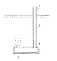
- the lance pipe 1 has a shape in which a bottomed cylinder is L-shaped, and includes a gas introduction pipe 2 and a tip porous portion 3 joined thereto. ing.
- the gas introduction pipe 2 is formed in a cylindrical shape and has a configuration in which a blown gas flows inside, and can blow the blown gas into the tip porous portion 3.
- the tip porous portion 3 is formed in a cylindrical shape with both end faces closed, and each face is made porous, and the blown gas flowing in from the gas introduction pipe 2 permeates each face from the inside and passes through the molten metal. It is configured to be blown inside.
- the gas introduction tube 2 has a material strength ratio (gas introduction tube strength / tip porous portion strength) to the tip porous portion 3 of 20 to 500, preferably 50 to 200. By making the material strength ratio within this range, the gas introduction tube 2 is not damaged when the tip porous portion 3 is removed. These strengths can be adjusted by selecting the material. The material strength can be measured according to a three-point bending strength test, JIS R2213.
- the gas introduction tube 2 is preferably formed of ceramics or the like, and the tip porous portion 3 is preferably formed of porous carbon.
- ceramics include silicon nitride ceramics, sialon ceramics, silicon carbide ceramics, and silicon nitride bonded silicon carbide refractories.
- the tip porous portion 3 preferably has an average pore diameter of 20 ⁇ m to 200 ⁇ m and a porosity of 30 to 50%. By setting it within this range, the bubble discharge stability is improved.
- the average pore diameter can be measured by a mercury porosimeter, and the porosity can be measured by the Archimedes method.
- a screw thread of the screw portion 4 is formed on the outer peripheral surface, and a circular hole having a screw groove of the screw portion 4 is formed on the peripheral surface of the distal end porous portion 3.
- the thickness of the gas introduction tube 2 is preferably 5 mm to 20 mm, and the thickness of the porous tip 3 is preferably 10 mm to 50 mm.
- the gas introduction pipe 2 can be formed by cold isostatic pressing, compaction molding, extrusion molding, cast molding, or the like.
- the tip porous portion 3 can be formed by cold isostatic pressing, press molding, extrusion molding, or the like. Can be formed.
- the gas introduction pipe 2 is formed of a material stronger than the tip porous portion 3, and thus the gas introduction pipe 2 can be used repeatedly over a long period of time, and these are detachable.
- the tip porous portion 3 that is easily damaged can be easily replaced.
- the lance pipe shown in FIG. 1 or FIG. 2 is formed in an L shape, a T type in which a gas introduction pipe is connected in the vicinity of the middle of the tip porous portion or a gas in the tip porous portion in a straight line. It can also be formed in a straight type connected to the introduction pipe, or a square shape in which the porous end portion is connected to the gas introduction pipe at a predetermined angle.
- the gas introduction pipes of Examples 1 to 3 and 7 and Comparative Examples 1 to 5 were prepared to have an inner diameter of 20 mm and a thickness of 10 mm. It was made of porous carbon with an inner diameter of 30 mm and a thickness of 15 mm.
- the gas introduction pipes of Examples 4 to 6 and 8 to 11 were produced with an inner diameter of 20 mm and a thickness of 5 mm, and the tip porous part was made of porous carbon with an inner diameter of 25 mm and a thickness of 15 mm.
- Screw processing was performed by lathe processing. When screw processing was not performed, it joined by inorganic adhesive or fitting.
- the average pore diameter was measured with a mercury porosimeter.
- test Using the lance pipes of Examples 1 to 11 and Comparative Examples 1 to 5, tests were conducted for breakage during tip replacement, aluminum corrosion resistance, gas leakage from the joint, and bubble release stability.
- the lance pipe is immersed in molten aluminum at 750 ° C. for 1 week while flowing the blown gas, and after cooling to room temperature, the gas introduction part and the tip porous part are removed, and the gas introduction part is not damaged at that time. It was confirmed visually. The case where damage was not confirmed was evaluated as “ ⁇ ”, and the case where damage was confirmed was evaluated as “x”.
Landscapes
- Engineering & Computer Science (AREA)
- Chemical & Material Sciences (AREA)
- Mechanical Engineering (AREA)
- Manufacturing & Machinery (AREA)
- Materials Engineering (AREA)
- Metallurgy (AREA)
- Organic Chemistry (AREA)
- Treatment Of Steel In Its Molten State (AREA)
- Manufacture And Refinement Of Metals (AREA)
- Porous Artificial Stone Or Porous Ceramic Products (AREA)
- Furnace Charging Or Discharging (AREA)
Abstract
経済的な使用が可能なランスパイプを提供する。 本発明のランスパイプ1は、アルミニウム溶湯に吹き込みガスを導入するものであり、ガス導入管2の先端側に先端多孔質部3を着脱可能に設けてあり、先端多孔質部3に対するガス導入管2の素材強度比を20~500にしたことを特徴とする。ガス導入管2と先端多孔質部3とにネジ部4を設けて、これらを接合することが好ましい。
Description
本発明は、アルミニウム溶湯中に吹き込みガスを導入するランスパイプに関する。
保持炉などでは、アルミニウム溶湯中の水素ガスや不純物などを除去するために、溶湯中に窒素ガスなどの吹き込みガスを導入し、水素ガスや不純物などを吹き込みガス気泡中に取り込み除去する脱ガス処理が行われている。
アルミニウム溶湯中に吹き込みガスを導入するためには、例えば、L字型円筒状のランスパイプなどが用いられる。
このようなランスパイプとしては、例えば、金属製の管本体を多孔質性耐火材で被覆したものや、金属溶湯に浸漬させる先端表面部を、アルミナ、マグネシア及びジルコニアを含む不定形耐火物で構成したものがある(下記特許文献1,2参照)。
このようなランスパイプとしては、例えば、金属製の管本体を多孔質性耐火材で被覆したものや、金属溶湯に浸漬させる先端表面部を、アルミナ、マグネシア及びジルコニアを含む不定形耐火物で構成したものがある(下記特許文献1,2参照)。
また、ランスパイプ用の材料としては、粘土を2~10重量%と、アルミナ含有量が70重量%以上のアルミナセメントを1~8重量%と、残部が耐火性骨材を含む材料からなる不定形耐火組成物に、外掛けで、粒径が100μm以下で純度が99重量%以上の金属アルミニウムを0.3~1.5重量%配合してなるものがある(下記特許文献3参照)。
ランスパイプは、高温のアルミニウム溶湯中に浸漬させるものであるため、耐熱性や耐食性、耐熱衝撃(耐スポーリング)性などに優れていることが要求される。
従来のランスパイプは、主にセラミックスやカーボンなどで形成されているが、セラミックス素材は、耐熱性や耐食性に優れているが、予熱なしで溶湯中に浸漬させると熱衝撃により割れやすいという問題があり、カーボン素材は、強度的に弱く破損しやすいという問題があった。特に、ランスパイプの先端部は破損しやすいものであった。
このため、ランスパイプの製品寿命は短く、交換の頻度が多いものであり、コストのかかるものであった。
従来のランスパイプは、主にセラミックスやカーボンなどで形成されているが、セラミックス素材は、耐熱性や耐食性に優れているが、予熱なしで溶湯中に浸漬させると熱衝撃により割れやすいという問題があり、カーボン素材は、強度的に弱く破損しやすいという問題があった。特に、ランスパイプの先端部は破損しやすいものであった。
このため、ランスパイプの製品寿命は短く、交換の頻度が多いものであり、コストのかかるものであった。
そこで、本発明の目的は、経済的な使用が可能なランスパイプを提供することにある。
本発明のランスパイプは、アルミニウム溶湯に吹き込みガスを導入するランスパイプにおいて、ガス導入管の先端側に設けた先端多孔質部を着脱可能に設けてあり、先端多孔質部に対するガス導入管の素材強度比を20~500にしたことを特徴とする。
このガス導入管と先端多孔質部を無機接着剤及び/又はネジ加工で接合することができるようにするのが好ましい。
ガス導入管の素材は、窒化珪素系セラミックス、サイアロン系セラミックス、炭化珪素系セラミックス、窒化珪素結合炭化珪素耐火物を用いることができる。
先端多孔質部は、平均気孔径が20μm~200μm、かつ気孔率が30~50%である多孔質カーボンを用いることができる。
本発明のランスパイプは、ガス導入管と先端多孔質部とを着脱可能とし、先端多孔質部の素材強度を強くしたため、破損しにくいガス導入管は長期間に亘り使用でき、破損しやすい先端多孔質部のみを交換して経済的にしようすることができる。
なお、本発明でいう、アルミニウム溶湯は、アルミニウム合金溶湯を含むものである。
以下、本発明のランスパイプの一実施形態を説明する。但し、本発明の範囲は、これに限定されるものではない。
本発明の一実施形態のランスパイプ1は、図1又は2に示すように、有底円筒をL型にした形状としてあり、ガス導入管2と、それに接合した先端多孔質部3とを備えている。
ガス導入管2は、円筒状に形成してあり、内部を吹き込みガスが流れる構成としてあり、先端多孔質部3に吹き込みガスを送り出すことができる。
先端多孔質部3は、両端面を閉塞した円筒状に形成してあり、その各面を多孔質とし、ガス導入管2から流れ込んできた吹き込みガスが、内部から各面を透過して金属溶湯中に吹き込まれる構成としてある。
先端多孔質部3は、両端面を閉塞した円筒状に形成してあり、その各面を多孔質とし、ガス導入管2から流れ込んできた吹き込みガスが、内部から各面を透過して金属溶湯中に吹き込まれる構成としてある。
ガス導入管2は、先端多孔質部3に対する素材強度比(ガス導入管強度/先端多孔質部強度)を20~500、好ましくは50~200にする。素材強度比をこの範囲にすることにより、先端多孔質部3を取り外す際、ガス導入管2が破損することがない。これら強度は、材質を選定によって調整することができる。
素材強度は、3点曲げ強さ試験、JISR2213に準じて測定することができる。
素材強度は、3点曲げ強さ試験、JISR2213に準じて測定することができる。
ガス導入管2は、セラミックスなどで形成し、先端多孔質部3は、多孔質カーボンで形成することが好ましい。セラミックスとしては、窒化珪素系セラミックス、サイアロン系セラミックス、炭化珪素系セラミックス、窒化珪素結合炭化珪素耐火物などを挙げることができる。
先端多孔質部3は、平均気孔径を20μm~200μm、気孔率を30~50%にするのが好ましい。この範囲にすることにより、気泡の放出安定性が向上する。
平均気孔径は、水銀ポロシメーターにて測定することができ、気孔率は、アルキメデス法にて測定することができる。
平均気孔径は、水銀ポロシメーターにて測定することができ、気孔率は、アルキメデス法にて測定することができる。
ガス導入管2の先端側には、外周面にネジ部4のネジ山が形成してあり、先端多孔質部3の周面には、ネジ部4のネジ溝を有する円孔が形成してあり、これらを締結してガス導入管2と先端多孔質部3とを着脱可能に接合できるようにしてある。このようにネジ部を設けて接合できるようにすることにより、接合部からのガス漏れがなくなる。
本実施形態では、ネジ部4でガス導入管2と先端多孔質部3と接合してあるが、アルミナ-シリカ系等からなる無機接着剤を用いた接合や嵌め合わせによる接合などでもよく、ネジ部による接合、無機接着剤による接合、嵌め合わせによる接合を適宜組み合わせて接合してもよい。
本実施形態では、ネジ部4でガス導入管2と先端多孔質部3と接合してあるが、アルミナ-シリカ系等からなる無機接着剤を用いた接合や嵌め合わせによる接合などでもよく、ネジ部による接合、無機接着剤による接合、嵌め合わせによる接合を適宜組み合わせて接合してもよい。
ガス導入管2の厚みは、5mm~20mmが好ましく、先端多孔質部3の厚みは、10mm~50mmが好ましい。
ガス導入管2は、冷間静水圧成形、付き固め成形、押し出し成形、鋳込成形などで形成することができ、先端多孔質部3は、冷間静水圧成形、プレス成形、押し出し成形などで形成することができる。
ランスパイプ1は、ガス導入管2を先端多孔質部3よりも強度のある素材で形成したため、ガス導入管2は、長期に亘り繰り返し使用することができ、また、これらを着脱可能に形成したため、破損しやすい先端多孔質部3を容易に交換することができる。
なお、図1又は図2に示したランスパイプは、L型に形成してあるが、先端多孔質部の中間付近にガス導入管を連結したT型や、先端多孔質部を直線状にガス導入管に連結したストレート型や、先端多孔質部を所定の角度をもってガス導入管に連結したくの字型などに形成することもできる。
以下、本発明を実施例に基づいて、より具体的に説明する。ただし、本発明の範囲は、この実施例に限定されるものではない。
下記表1及び表2に記載されている素材を用いて、実施例1~3、7及び比較例1~5のガス導入管は、内径20mm、厚み10mmに作製し、先端多孔質部は、多孔質カーボンで内径30mm、厚み15mmに作製した。また、実施例4~6、8~11のガス導入管は、内径20mm、厚み5mmに作製し、先端多孔質部は、多孔質カーボンで内径25mm、厚み15mmに作製した。


(強度)
強度は、3点曲げ強さ試験、JISR2213に準じて測定した。
強度は、3点曲げ強さ試験、JISR2213に準じて測定した。
(接合)
ネジ加工は、旋盤加工で行った。ネジ加工を施さない場合は、無機接着剤又は嵌め合わせで接合した。
ネジ加工は、旋盤加工で行った。ネジ加工を施さない場合は、無機接着剤又は嵌め合わせで接合した。
(平均気孔径)
平均気孔径は、水銀ポロシメーターで測定した。
平均気孔径は、水銀ポロシメーターで測定した。
(気孔率)
気孔率は、アルキメデス法で測定した。
気孔率は、アルキメデス法で測定した。
(試験)
実施例1~11及び比較例1~5のランスパイプを用いて、先端交換時の破損、アルミ耐食性、接合部からのガス漏れ、気泡放出安定性について試験を行った。
実施例1~11及び比較例1~5のランスパイプを用いて、先端交換時の破損、アルミ耐食性、接合部からのガス漏れ、気泡放出安定性について試験を行った。
(先端交換時の破損)
吹き込みガスを流しながら、ランスパイプを750℃のアルミニウム溶湯に1週間浸漬させて取り出し、常温に冷却した後、ガス導入部と先端多孔質部とを外し、その際にガス導入部に破損がないかを目視にて確認した。破損が確認されない場合を「○」、破損が確認された場合を「×」として評価した。
吹き込みガスを流しながら、ランスパイプを750℃のアルミニウム溶湯に1週間浸漬させて取り出し、常温に冷却した後、ガス導入部と先端多孔質部とを外し、その際にガス導入部に破損がないかを目視にて確認した。破損が確認されない場合を「○」、破損が確認された場合を「×」として評価した。
(アルミ耐食性)
吹き込みガスを流しながら、ランスパイプを750℃のアルミニウム溶湯に1週間浸漬させて取り出し、常温に冷却することを3回繰り返し、折損がない場合を「○」、折損が発生した場合を「×」として評価した。
吹き込みガスを流しながら、ランスパイプを750℃のアルミニウム溶湯に1週間浸漬させて取り出し、常温に冷却することを3回繰り返し、折損がない場合を「○」、折損が発生した場合を「×」として評価した。
(接合部からのガス漏れ)
ランスパイプを水槽内に浸漬させ、空気を20L/minで送り込み、接合部からガスが漏れていないかを目視にて確認した。ガス漏れが確認されない場合を「○」、ガス漏れが確認された場合を「×」として評価した。
ランスパイプを水槽内に浸漬させ、空気を20L/minで送り込み、接合部からガスが漏れていないかを目視にて確認した。ガス漏れが確認されない場合を「○」、ガス漏れが確認された場合を「×」として評価した。
(気泡放出安定性)
ランスパイプを水槽内に浸漬させ、空気を20L/minで送り込み、気泡の放出具合を目視にて確認した。多孔質部全域から均一に気泡が放出された場合を「○」、気泡の放出にムラがある場合を「×」として評価した。
ランスパイプを水槽内に浸漬させ、空気を20L/minで送り込み、気泡の放出具合を目視にて確認した。多孔質部全域から均一に気泡が放出された場合を「○」、気泡の放出にムラがある場合を「×」として評価した。
(総合評価)
先端交換時の破損がなく、さらに、他の3評価項目中、2つ以上が○の場合を「◎」、先端交換時の破損がなく、さらに、他の3評価項目中、1つが○の場合を「○」、先端交換時の破損があり、さらに、他の3評価項目中、1つ以上が○の場合を「△」、先端交換時の破損があり、さらに、他の3評価項目の全てが×の場合を「×」として評価した。
先端交換時の破損がなく、さらに、他の3評価項目中、2つ以上が○の場合を「◎」、先端交換時の破損がなく、さらに、他の3評価項目中、1つが○の場合を「○」、先端交換時の破損があり、さらに、他の3評価項目中、1つ以上が○の場合を「△」、先端交換時の破損があり、さらに、他の3評価項目の全てが×の場合を「×」として評価した。
(結果)
実施例1~11は、総合評価「◎」又は「○」であり、良好な結果であった。
一方、比較例1~5は、総合評価「△」又は「×」であり、好ましくない結果であった。
実施例1~11の結果から、先端多孔質部に対するガス導入管の素材強度比が25(実施例1~3)~475(実施例4)の範囲であれば、先端交換時にガス導入管の破損が見られないことが確認された。
比較例1~5の結果から、該素材強度比が6又は5であるとガス導入管の破損が生ずることが確認された。
これら結果から、先端多孔質部に対するガス導入管の素材強度比は、20~500の範囲であれば、先端交換時のガス導入管の破損が生じないものと思われる。
実施例1~11は、総合評価「◎」又は「○」であり、良好な結果であった。
一方、比較例1~5は、総合評価「△」又は「×」であり、好ましくない結果であった。
実施例1~11の結果から、先端多孔質部に対するガス導入管の素材強度比が25(実施例1~3)~475(実施例4)の範囲であれば、先端交換時にガス導入管の破損が見られないことが確認された。
比較例1~5の結果から、該素材強度比が6又は5であるとガス導入管の破損が生ずることが確認された。
これら結果から、先端多孔質部に対するガス導入管の素材強度比は、20~500の範囲であれば、先端交換時のガス導入管の破損が生じないものと思われる。
Claims (4)
- アルミニウム溶湯に吹き込みガスを導入するランスパイプにおいて、ガス導入管の先端側に先端多孔質部を着脱可能に設けてあり、先端多孔質部に対するガス導入管の素材強度比を20~500にしたランスパイプ。
- ガス導入管と先端多孔質部を無機接着剤及び/又はネジ加工により接合した請求項1に記載のランスパイプ。
- ガス導入管の素材に窒化珪素系セラミックス、サイアロン系セラミックス、炭化珪素系セラミックス、窒化珪素結合炭化珪素耐火物を用いた請求項1又は2に記載のランスパイプ。
- 先端多孔質部に平均気孔径が20μm~200μm、かつ気孔率が30~50%である多孔質カーボンを用いた請求項1~3のいずれかに記載のランスパイプ。
Priority Applications (1)
| Application Number | Priority Date | Filing Date | Title |
|---|---|---|---|
| CN2010800252553A CN102459664A (zh) | 2009-06-08 | 2010-05-26 | 吹管 |
Applications Claiming Priority (2)
| Application Number | Priority Date | Filing Date | Title |
|---|---|---|---|
| JP2009-137015 | 2009-06-08 | ||
| JP2009137015A JP5414375B2 (ja) | 2009-06-08 | 2009-06-08 | ランスパイプ |
Publications (1)
| Publication Number | Publication Date |
|---|---|
| WO2010143536A1 true WO2010143536A1 (ja) | 2010-12-16 |
Family
ID=43308791
Family Applications (1)
| Application Number | Title | Priority Date | Filing Date |
|---|---|---|---|
| PCT/JP2010/058906 Ceased WO2010143536A1 (ja) | 2009-06-08 | 2010-05-26 | ランスパイプ |
Country Status (3)
| Country | Link |
|---|---|
| JP (1) | JP5414375B2 (ja) |
| CN (1) | CN102459664A (ja) |
| WO (1) | WO2010143536A1 (ja) |
Families Citing this family (3)
| Publication number | Priority date | Publication date | Assignee | Title |
|---|---|---|---|---|
| US20140210144A1 (en) * | 2013-01-31 | 2014-07-31 | Pyrotek | Composite degassing tube |
| JP6300414B2 (ja) * | 2014-11-20 | 2018-03-28 | 明智セラミックス株式会社 | ランスパイプ |
| CN110358928A (zh) * | 2018-04-10 | 2019-10-22 | 无锡刚正精密吸铸有限公司 | 金属液除气器 |
Citations (4)
| Publication number | Priority date | Publication date | Assignee | Title |
|---|---|---|---|---|
| JPS6197161A (ja) * | 1984-10-17 | 1986-05-15 | ハリマセラミック株式会社 | ガス吹込用ポーラス耐火物の製造法 |
| JPS6386825A (ja) * | 1986-09-30 | 1988-04-18 | Hitachi Metals Ltd | アルミニウム溶湯用ガス吹込管 |
| JPH05302131A (ja) * | 1992-04-27 | 1993-11-16 | Nippon Carbon Co Ltd | 溶融金属浴へのガス吹込管 |
| JP2000345249A (ja) * | 1999-06-02 | 2000-12-12 | Sumitomo Chem Co Ltd | 酸化性ガス吹込み管 |
Family Cites Families (5)
| Publication number | Priority date | Publication date | Assignee | Title |
|---|---|---|---|---|
| JPH11256221A (ja) * | 1998-03-12 | 1999-09-21 | Tokyo Yogyo Co Ltd | バブリングランスパイプ |
| JP3823132B2 (ja) * | 2001-03-13 | 2006-09-20 | 品川白煉瓦株式会社 | ランスパイプ用不定形耐火組成物 |
| DE102004015357B4 (de) * | 2004-03-30 | 2011-08-18 | Schott Ag, 55122 | Verfahren zur Behandlung von Feuerfestmaterial und Verwendung sowie Verfahren zur Herstellung und/oder Verarbeitung von Glasschmelzen und Vorrichtung |
| JP5247015B2 (ja) * | 2006-05-29 | 2013-07-24 | 日本坩堝株式会社 | ランスパイプ、脱ガス処理器、脱ガス処理器付き容器及び脱ガス処理器付き樋 |
| CN201031250Y (zh) * | 2007-05-17 | 2008-03-05 | 天津市天炉科技发展有限公司 | 侧吹喷流加热式铝卷材退火炉 |
-
2009
- 2009-06-08 JP JP2009137015A patent/JP5414375B2/ja active Active
-
2010
- 2010-05-26 WO PCT/JP2010/058906 patent/WO2010143536A1/ja not_active Ceased
- 2010-05-26 CN CN2010800252553A patent/CN102459664A/zh active Pending
Patent Citations (4)
| Publication number | Priority date | Publication date | Assignee | Title |
|---|---|---|---|---|
| JPS6197161A (ja) * | 1984-10-17 | 1986-05-15 | ハリマセラミック株式会社 | ガス吹込用ポーラス耐火物の製造法 |
| JPS6386825A (ja) * | 1986-09-30 | 1988-04-18 | Hitachi Metals Ltd | アルミニウム溶湯用ガス吹込管 |
| JPH05302131A (ja) * | 1992-04-27 | 1993-11-16 | Nippon Carbon Co Ltd | 溶融金属浴へのガス吹込管 |
| JP2000345249A (ja) * | 1999-06-02 | 2000-12-12 | Sumitomo Chem Co Ltd | 酸化性ガス吹込み管 |
Also Published As
| Publication number | Publication date |
|---|---|
| CN102459664A (zh) | 2012-05-16 |
| JP2010279988A (ja) | 2010-12-16 |
| JP5414375B2 (ja) | 2014-02-12 |
Similar Documents
| Publication | Publication Date | Title |
|---|---|---|
| TWI542557B (zh) | A method for manufacturing a molten glass conveying apparatus, and a method for manufacturing a molten glass conveying apparatus, and a glass manufacturing apparatus | |
| JP5016609B2 (ja) | 高耐用性スリーブれんが | |
| TWI564260B (zh) | A method of manufacturing a molten glass conveying apparatus, a glass manufacturing apparatus including a glass member for a molten glass conveyance apparatus, and a method for manufacturing a glass article | |
| CN110563451A (zh) | 一种陶瓷质钢包浇注料及其制备方法 | |
| CN102452836A (zh) | 用于快速烘烤钢包的无水泥铝镁质浇注料 | |
| JP5414375B2 (ja) | ランスパイプ | |
| CN103880442B (zh) | 刚玉-尖晶石质浇注料及其制备rh插入管预制件内芯的方法 | |
| CN102164695B (zh) | 用于连续铸造的浇注嘴用耐火物及连续铸造用浇注嘴 | |
| CN101121602A (zh) | 中间包用弥散式镁质透气砖 | |
| JP2015218078A (ja) | 軽量断熱アルミナ・マグネシア質耐火物 | |
| CN111957951B (zh) | 一种耐火浇注料用改性铝粉的制备方法和用途 | |
| CN104944990A (zh) | 一种浇注料 | |
| US8986598B2 (en) | Alumina-coated spinel-silicon carbide refractory composition with high corrosion resistance to coal slag and method for manufacturing the same | |
| CN102432307A (zh) | 耐火浇注料用粉末组合物和使用其的耐火浇注料 | |
| JP2011057536A (ja) | スピネル質耐火物 | |
| JPH05285612A (ja) | 連続鋳造用ノズル内孔体 | |
| CN100408515C (zh) | 一种用于辊底炉炉辊的耐火浇注料 | |
| CN105294131B (zh) | 一种高分散性MgO‑MgAl2O4‑ZrO2材料的制备方法 | |
| TW201141811A (en) | Flame retardant substance, nozzle made of flame retardant substance and used in continuous casting, production method of nozzle used in continuous casting, and continuous casting method of using nozzle thereof | |
| CN104311065A (zh) | 耐火自流浇注料 | |
| JP2009242122A (ja) | 高炉炉床用れんが及びこれをライニングした高炉炉床 | |
| TW202124329A (zh) | CaO-ZrO組成物、CaO-ZrO組成物之製造方法、含CaO-ZrO之耐火物及鑄造用噴嘴 | |
| JPH11256221A (ja) | バブリングランスパイプ | |
| CN102221408A (zh) | 钢水连续测温用红外测温管及其组分、制备方法 | |
| JPH06239667A (ja) | 多孔質サイアロン焼結体 |
Legal Events
| Date | Code | Title | Description |
|---|---|---|---|
| WWE | Wipo information: entry into national phase |
Ref document number: 201080025255.3 Country of ref document: CN |
|
| 121 | Ep: the epo has been informed by wipo that ep was designated in this application |
Ref document number: 10786067 Country of ref document: EP Kind code of ref document: A1 |
|
| NENP | Non-entry into the national phase |
Ref country code: DE |
|
| 122 | Ep: pct application non-entry in european phase |
Ref document number: 10786067 Country of ref document: EP Kind code of ref document: A1 |