WO2010146694A1 - Dispositif d'émission et dispositif de réception - Google Patents
Dispositif d'émission et dispositif de réception Download PDFInfo
- Publication number
- WO2010146694A1 WO2010146694A1 PCT/JP2009/061126 JP2009061126W WO2010146694A1 WO 2010146694 A1 WO2010146694 A1 WO 2010146694A1 JP 2009061126 W JP2009061126 W JP 2009061126W WO 2010146694 A1 WO2010146694 A1 WO 2010146694A1
- Authority
- WO
- WIPO (PCT)
- Prior art keywords
- information
- bit
- unit
- information bits
- bits
- Prior art date
- Legal status (The legal status is an assumption and is not a legal conclusion. Google has not performed a legal analysis and makes no representation as to the accuracy of the status listed.)
- Ceased
Links
Images








Classifications
-
- H—ELECTRICITY
- H04—ELECTRIC COMMUNICATION TECHNIQUE
- H04L—TRANSMISSION OF DIGITAL INFORMATION, e.g. TELEGRAPHIC COMMUNICATION
- H04L1/00—Arrangements for detecting or preventing errors in the information received
- H04L1/004—Arrangements for detecting or preventing errors in the information received by using forward error control
- H04L1/0056—Systems characterized by the type of code used
- H04L1/0067—Rate matching
-
- H—ELECTRICITY
- H04—ELECTRIC COMMUNICATION TECHNIQUE
- H04L—TRANSMISSION OF DIGITAL INFORMATION, e.g. TELEGRAPHIC COMMUNICATION
- H04L1/00—Arrangements for detecting or preventing errors in the information received
- H04L1/004—Arrangements for detecting or preventing errors in the information received by using forward error control
- H04L1/0056—Systems characterized by the type of code used
- H04L1/0064—Concatenated codes
- H04L1/0065—Serial concatenated codes
-
- H—ELECTRICITY
- H04—ELECTRIC COMMUNICATION TECHNIQUE
- H04L—TRANSMISSION OF DIGITAL INFORMATION, e.g. TELEGRAPHIC COMMUNICATION
- H04L1/00—Arrangements for detecting or preventing errors in the information received
- H04L1/004—Arrangements for detecting or preventing errors in the information received by using forward error control
- H04L1/0056—Systems characterized by the type of code used
- H04L1/0071—Use of interleaving
Definitions
- the present invention relates to a transmission apparatus and the like for encoding and modulating information bits.
- turbo code As an encoding method for encoding information bits, there are multilevel modulation and hierarchical modulation. Hereinafter, turbo code, multilevel modulation, and hierarchical modulation will be described.
- Turbo code is an encoding method that combines a plurality of element codes and an interleaver.
- a turbo code standardized by 3GPP (3rd Generation Partnership Project) will be described as an example.
- FIG. 12 is a diagram for explaining an example of a conventional turbo encoder.
- the turbo encoder 10 includes element encoders 20 and 30 and an interleaver 40.
- the element encoder 20 includes delay units 21 to 23, and the element encoder 30 includes delay units 31 to 33.
- feedback type convolutional coding is performed, and a parity bit sequence 1 is generated.
- the order of bit strings of the information bits input to the element encoder 30 is replaced by the interleaver 40.
- feedback type convolutional coding is performed, and a parity bit sequence 2 is generated.
- the turbo encoder 10 outputs a bit string obtained by serially combining the systematic bit sequence corresponding to the information bits, the parity bit sequence 1 and the parity bit sequence 2.
- FIG. 13 is a diagram for explaining an example of a conventional turbo decoder.
- the turbo decoder 50 includes element decoders 60 and 70, an interleaver 80, and a deinterleaver 90.
- the turbo decoder 50 decodes the encoded information bits based on the likelihood data y s , y p1 , y p2 .
- the likelihood data y s is an encoded sequence in which noise is added to the systematic bit sequence on the transmission path
- the likelihood data y p1 is an encoded sequence in which noise is added to the parity bit sequence 1 on the transmission path. It is.
- the likelihood data yp2 is an encoded sequence in which noise is added to the parity bit sequence 1.
- the interleaver 80 is an interleaver that performs replacement in the same order as the interleaver 40 shown in FIG.
- the deinterleaver 90 is an interleaver that returns the information bits replaced by the interleaver 80 to the original order.
- the element decoders 60 and 70 are decoders that determine posterior probabilities using, for example, MAP decoding (Maximum A Posteriori Probability decoding) or SOVA (Soft Output Viterbi Algorithm). It is.
- the element decoder 60 repeatedly performs error correction decoding of the likelihood data y s using the redundant bits of the likelihood data y p1 and the posterior probability obtained by the element decoder 70 to obtain the posterior probability.
- the element decoder 60 outputs the obtained posterior probability to the element decoder 70 via the interleaver 80.
- the element decoder 70 repeatedly performs error correction decoding of the likelihood data y s using the redundant bits of the likelihood data y p2 and the posterior probability obtained by the element decoder 60 to obtain the posterior probability.
- the element decoder 70 outputs the obtained posterior probability to the element decoder 60 via the deinterleaver 90. Further, the posterior probability obtained by the element decoder 70 becomes the decoded information bit.
- the element decoders 60 and 70 repeatedly perform error correction decoding, thereby improving error correction capability.
- the QPSK (four-phase transition modulation) method is a modulation method in which the amplitude is fixed and 2-bit information is assigned to four phases.
- FIG. 14 is a diagram for explaining the QPSK method.
- the vertical axis is an imaginary axis
- the horizontal axis is a real number axis.
- Each bit pattern (00, 10, 11, 01) is represented by a symbol represented by a specific phase.
- the reliability of 2 bits (the first bit and the second bit) is the same.
- multi-level modulation is a modulation scheme that transmits an amount of information higher than the QPSK scheme by assigning each binary bit a combination of different amplitudes and different phases.
- FIG. 15 is a diagram for explaining 16QAM, which is an example of a multi-level modulation method.
- the vertical axis is an imaginary axis
- the horizontal axis is a real axis.
- 16QAM 4-bit information is assigned to each combination of four amplitudes and four phases.
- 16QAM has 16 symbols.
- the reliability of 4 bits (the 1st bit, the 2nd bit, the 3rd bit, and the 4th bit) is not all the same, and bias occurs. Specifically, the reliability of the first bit and the third bit is different, and the reliability of the second bit and the fourth bit are different.
- the gradation modulation method is a method of assigning information bits assigned to one symbol to different users in multilevel modulation. For example, among the 4 bits assigned to one symbol, the first bit is assigned to user A, the second bit is assigned to user B, the third bit is assigned to user C, and the fourth bit is assigned to user D.
- FIG. 16 is a diagram for explaining the gradation modulation method.
- the bandwidth B is divided into a plurality of resource blocks (RB), and symbols are allocated to a part of the resource blocks. Then, one bit among the information bits corresponding to the symbol is assigned to the user. For example, in FIG. 16, when RB0 and RB1 are assigned to user A, the first bit of the bit strings of the symbols of RB0 and RB1 is the bit assigned to user A.
- FIG. 17 is a diagram illustrating fading of radio waves transmitted to user A and fading of radio waves transmitted to user B.
- BICM Bit Interleaved coded modulation
- MLC Multi Level Coding
- FIG. 18 is a diagram showing a configuration of a BICM transmitter.
- the transmitter 100 includes an encoding unit 101 that encodes information bits, similarly to the turbo encoder.
- it includes a channel interleaver 102 that rearranges the order of encoded information bits, and a modulation unit 103 that performs multilevel modulation or hierarchical modulation.
- FIG. 19 is a diagram illustrating a configuration of an MLC transmitter.
- the transmitter 110 includes a dividing unit 111, encoding units 112a and 112b, channel interleavers 113a and 113b, and a multilevel modulation unit 114.
- the dividing unit 111 is a processing unit that divides an information bit into two, outputs one divided information bit to the encoding unit 112a, and outputs the other information bit to the encoding unit 112b.
- Encoder 112a encodes information bits and outputs the encoded information bits to channel interleaver 113a.
- Encoding section 112b encodes information bits and outputs the encoded information bits to channel interleaver 113b.
- the channel interleaver 113a replaces the order of the encoded information bits, and outputs the replaced information bits to the multi-level modulation unit 114.
- Channel interleaver 113b replaces the order of the encoded information bits, and outputs the replaced information bits to multilevel modulation section 114.
- the multi-level modulation unit 114 assigns the information bits acquired from the interleave 113a to the first bit and the second bit (L0) and acquires them from the interleave 113b.
- the assigned information bits are assigned to the third bit and the fourth bit (L1). Then, the information bits are transmitted by modulating the signal to have an amplitude and phase corresponding to the assigned symbols.
- the coding rate of the information bits assigned to the levels L0 and L1 is determined by the encoding units 112a and 112b in consideration of the difference in transmission quality of the information bits assigned to the levels L0 and L1. By adjusting, the overall error rate specification is improved.
- MSD Multi Stage Decoding
- MSD is known as a means for decoding information bits encoded by the MLC method.
- the MLC method although the reliability can be made constant, even if the code length is small, the code needs to be divided into two or more.
- the turbo code has a characteristic that the characteristic is deteriorated when the code length is small. Therefore, the MLC method has a problem that the characteristic is deteriorated according to the code length. In addition, the MLC method is easily affected by deterioration in reliability of partial likelihood data in fading.
- the present invention has been made in order to solve the above-described problems of the prior art, and provides a transmission apparatus and the like that stabilize the reliability of each bit included in an information bit while suppressing characteristic deterioration. With the goal.
- the transmitting apparatus includes a first element encoder that encodes information bits to generate a first parity bit sequence, and an information bit in which a bit string is replaced
- a second element encoder that generates a second parity bit sequence by encoding the information, generates information obtained by combining a part of the information bits and the first parity bit sequence, and a bit size of the generated information
- a first rate matching unit that adjusts, a second rate matching unit that generates information by combining a part of the information bits and the second parity bit sequence, and adjusts the bit size of the generated information
- a bit string combining information output from the first rate matching unit and information output from the second rate matching unit is generated, and a multi-value variable is generated based on the bit string. Having a multi-level modulator for the execution and requirements.
- this transmission apparatus it is possible to equalize the reliability of each bit included in the information bits while suppressing characteristic deterioration.
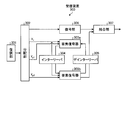
- FIG. 1 is a diagram illustrating the configuration of the transmission apparatus according to the first embodiment.
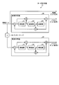
- FIG. 2 is a diagram illustrating a structure of information output from the P / S conversion unit 124a.
- FIG. 3 is a diagram illustrating a structure of information output from the P / S conversion unit 124b.
- FIG. 4 is a diagram illustrating a structure of information with repetition added.
- FIG. 5 is a diagram illustrating a structure of information when puncturing is performed.
- FIG. 6 is a diagram of the configuration of the receiving apparatus according to the first embodiment.
- FIG. 7 is a diagram illustrating a processing procedure of the transmission apparatus according to the first embodiment.
- FIG. 8 is a diagram illustrating the configuration of the transmission apparatus according to the second embodiment.
- FIG. 1 is a diagram illustrating the configuration of the transmission apparatus according to the first embodiment.
- FIG. 2 is a diagram illustrating a structure of information output from the P / S conversion unit 124a.
- FIG. 3 is a diagram illustrating
- FIG. 9 is a diagram illustrating a structure of information output from the encoding unit.
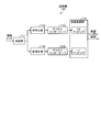
- FIG. 10 is a diagram illustrating the configuration of the receiving apparatus according to the second embodiment.
- FIG. 11 is a diagram for explaining other processes of the multi-level modulation unit.
- FIG. 12 is a diagram for explaining an example of a conventional turbo encoder.
- FIG. 13 is a diagram for explaining an example of a conventional turbo decoder.
- FIG. 14 is a diagram for explaining the QPSK method.
- FIG. 15 is a diagram for explaining 16QAM, which is an example of a multi-level modulation method.
- FIG. 16 is a diagram for explaining the gradation modulation method.
- FIG. 17 is a diagram illustrating fading of radio waves transmitted to user A and fading of radio waves transmitted to user B.
- FIG. 18 is a diagram illustrating a configuration of a BICM transmitter.
- FIG. 19 is a diagram illustrating a configuration of an MLC transmitter.
- FIG. 1 is a diagram illustrating the configuration of the transmission apparatus according to the first embodiment.
- the transmission device 120 includes a control unit 120a, an interleaver 121, element encoders 122a and 122b, a distribution switch 123, P / S conversion units 124a and 124b, channel interleavers 125a and 125b, and rate matching. Sections 126a and 126b, and a multi-level modulation section 127.
- the control unit 120a Based on the size K of information bits, the number N of code bits corresponding to the number of encoded information bits, and the coding rate R0 of the rate matching 126a, the control unit 120a distributes the information bit size K0 distributed by the distribution switch. , K1, and rate matching 126b coding rate R1 is calculated. It is assumed that the information bit size K, the number of code bits N, and the coding rate R0 are stored in advance in the control unit 120a.
- the control unit 120a outputs the information bit sizes K0 and K1 to the distribution switch 123. Also, the control unit 120a outputs the coding rate R0 to the rate matching unit 126a, and outputs the coding rate R1 to the rate matching unit 126b.
- the interleaver 121 is a processing unit that replaces the order of information bits when information bits are acquired. Interleaver 121 outputs the replaced information bits to element encoder 122b.
- the element encoder 122a is an encoder that performs feedback type convolutional coding and outputs a parity bit sequence 1 in the same manner as the element encoder 20 shown in FIG. 12 when information bits are acquired.
- the element encoder 122a When the element encoder 122a acquires the information bits whose order has been replaced by the interleaver 121, the element encoder 122a performs feedback type convolutional coding in the same manner as the element encoder 30 shown in FIG. Is an encoder that outputs.
- the distribution switch 123 acquires the information bit sizes K0 and K1 from the control unit 120a, outputs the information bits of the size K0 out of all the information bit sizes acquired from the outside to the P / S conversion unit 124a, and outputs the size K1. Is a switch that outputs the information bits to the P / S converter 124b.
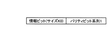
- the P / S converter 124a combines the parity bit sequence 1 acquired from the element encoder 122a and the information bit of size K0 acquired from the distribution switch 123, and outputs the combined information to the channel interleaver 125a. It is.
- FIG. 2 is a diagram illustrating a structure of information output from the P / S conversion unit 124a.
- the P / S converter 124b combines the parity bit sequence 2 acquired from the element encoder 122b and the information bit of size K1 acquired from the distribution switch 123, and outputs the combined information to the channel interleaver 125b. It is.
- FIG. 3 is a diagram illustrating a structure of information output from the P / S conversion unit 124b.
- the channel interleaver 125a is a processing unit that, when acquiring information obtained by combining information bits and the parity bit sequence 1, divides the acquired information into a plurality of data units and rearranges these data units according to a predetermined rule.
- the channel interleaver 125a outputs the rearranged information to the rate matching unit 126a.
- the channel interleaver 125b is a processing unit that divides the acquired information into a plurality of data units and rearranges these data units according to a predetermined rule when information obtained by combining information bits and the parity bit sequence 2 is acquired. .
- Channel interleaver 125b outputs the rearranged information to rate matching unit 126a.
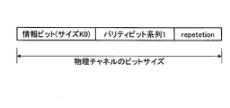
- the rate matching unit 126a is a processing unit that calculates the bit size of the physical channel based on the coding rate R0 and adjusts the size of the information acquired from the channel interleaver 125a so as to correspond to the calculated bit size. .
- the bit size of the physical channel is K0 + K. K0 is calculated by the above-described equation (1).
- FIG. 4 is a diagram showing the structure of information when repetition is added.
- FIG. 5 is a diagram illustrating a structure of information when puncturing is performed.
- the rate matching unit 126a outputs the information whose size has been adjusted to the multi-level modulation unit 127.
- the rate matching unit 126b is a processing unit that calculates the bit size of the physical channel based on the coding rate R1, and adjusts the size of the information acquired from the channel interleaver 125b so as to correspond to the calculated bit size. .
- the bit size of the physical channel is K1 + K.
- the multi-level modulation unit 127 is a processing unit that sequentially extracts a total of 4 bits by 2 bits from information acquired from the rate matching units 126a and 126b, maps symbols corresponding to the extracted 4 bits, and transmits information bits. .
- the multi-level modulation unit 127 associates the 2-bit information extracted from the information of the rate matching unit 126a with the first bit and the second bit (L0) of the four bits constituting the symbol. In addition, the multi-level modulation unit 127 associates the 2-bit information extracted from the information of the rate matching unit 126b with the 3rd bit and the 4th bit (L1) of the 4 bits constituting the symbol.
- the multi-level modulation unit 127 has the case where the 2-bit information extracted from the information of the rate matching unit 126a is “01” and the 2-bit information extracted from the information of the rate matching unit 126b is “10”. The symbol corresponding to the upper right of the fourth quadrant in FIG. 15 is mapped.
- the transmission apparatus 120 divides the information bits, calculates the parity bit sequences 1 and 2 from the divided information bits, and prevents the calculated parity bit sequence 1 and the parity bit sequence 2 from being added to the same information bit. Are combined with information bits (encoded information bits). Then, the transmission apparatus 120 replaces the order of the combined information and distributes the replaced information to the levels L0 and L1 to perform multilevel modulation, so that the influence of noise during transmission is determined for each bit of the information bits. The reliability of each bit included in the information bits is made constant.
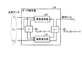
- FIG. 6 is a diagram illustrating a configuration of the receiving device 130 according to the first embodiment.
- the reception device 130 includes a demodulation unit 131, a distribution unit 132, element decoders 133a and 133b, an interleaver 134, and a deinterleaver 135.
- the demodulation unit 131 is a processing unit that acquires the modulated information from the transmission device 120 and demodulates the acquired information. Demodulation section 131 outputs the demodulated information to distribution section 132.
- the distribution unit 132 When the distribution unit 132 acquires information from the demodulation unit 131, the distribution unit 132 extracts likelihood data y s , y p1 , and y p2 from the acquired information. Distribution section 132 then outputs likelihood data y s to element decoder 133a and interleaver 134, and outputs likelihood data y p1 to element decoder 133a. Distribution section 132 outputs likelihood data yp2 to element decoder 133b.
- the element decoders 133a and 133b are decoders that obtain the posterior probabilities by, for example, MAP decoding or SOVA soft output decoding algorithm in the same manner as the element decoders 60 and 70 shown in FIG.
- the element decoder 133a repeatedly performs error correction decoding on the likelihood data y s by using the redundant bits of the likelihood data y p1 and the posterior probability obtained by the element decoder 70 to obtain the posterior probability.
- the element decoder 60 outputs the obtained posterior probability to the element decoder 133b via the interleaver 134.
- the element decoder 133b repeatedly performs error correction decoding of the likelihood data y s by using the redundant bits of the likelihood data y p2 and the posterior probability obtained by the element decoder 60, and obtains the posterior probability.
- the element decoder 133b outputs the obtained posterior probability to the element decoder 133a via the deinterleaver 135. Further, the posterior probability obtained by the element decoder 133b becomes the decoded information bit.
- element decoders 133a and 133b repeatedly perform error correction decoding, thereby improving error correction capability.
- the interleaver 134 is an interleaver that replaces the order of the likelihood data y s .
- the deinterleaver 135 is an interleaver that replaces the order of the bit sequence of the posterior probabilities so that the reverse order of the interleaver 134 is obtained.
- Receiving device 130 performs decoding processing first from the one with the lowest coding rate. For example, in FIG. 1, when the coding rate R0 of the rate matching unit 126a is lower than the coding rate R1 of the rate matching unit 126b, the likelihood data y p1 is more encoded than the likelihood data y p2. The conversion rate becomes low. In this case, the element decoder 133a executes the decoding process first, and then the element decoder 133b executes the decoding process. The information of the coding rates R0 and R1 may be held in advance by the element decoders 133a and 133b.
- FIG. 7 is a diagram illustrating a processing procedure of the transmission apparatus according to the first embodiment.
- the control unit 120a obtains the information bit size K, the number N of coded bits, and the coding rate R0 (step S101), and the divided information bit sizes K0 and K1, and the coding.
- the rate R1 is calculated (step S102).
- Element encoders 122a and 122b generate parity bit sequences 1 and 2 (step S103), and P / S converters 124a and 124b combine information bits (systematic bit sequences) and parity bit sequences (step S104). .
- the channel interleavers 125a and 125b replace the arrangement order of the bit strings (step S105), and the rate matching unit 126a adjusts the bit size based on the coding rate (step S106). Then, the multi-level modulation unit 127 performs modulation based on the information acquired from the rate matching units 126a and 126b (step S107).
- the transmission apparatus 120 divides information bits, calculates parity bit sequences 1 and 2 from the divided information bits, and the calculated parity bit sequence 1 and parity bit sequence 2 are It is combined with information bits (encoded information bits) so as not to be added to the same information bits. Then, the transmission apparatus 120 replaces the order of the combined information and distributes the replaced information to the levels L0 and L1 to perform multilevel modulation, so that the influence of noise during transmission is determined for each bit of the information bits. And the reliability of each bit included in the information bits is made equal.
- the modulation scheme is described as a multi-level modulation scheme as an example.
- the modulation scheme is not limited to the multi-level modulation, and the hierarchical modulation scheme described in FIG. 16 is used. May be used.
- FIG. 8 is a diagram illustrating the configuration of the transmission apparatus according to the second embodiment.
- the transmission apparatus 200 includes a control unit 200a, an interleaver 201, element encoders 202a and 202b, a distribution switch 203, P / S conversion units 204a and 204b, channel interleavers 205a, 205b, and 209, Rate matching units 206 a, 206 b, 210, a dividing unit 207, a coding unit 208, and a multilevel modulation unit 211 are included.
- interleaver 201 the element encoders 202a and 202b, the distribution switch 203, the P / S converters 204a and 204b, the channel interleavers 205a and 205b, and the rate matching units 206a and 206b is described in the control shown in FIG. Unit 120a, interleaver 121, element encoders 122a and 122b, distribution switch 123, P / S converters 124a and 124b, channel interleavers 125a and 125b, and rate matching unit 126a.
- the dividing unit 207 is a processing unit that divides information bits based on a preset ratio.
- the dividing unit 207 outputs one divided information bit to the encoding unit 208, and outputs the other information bit to the interleaver 201, the element encoder 202a, and the distribution switch 203.
- the encoding unit 208 is a processing unit that generates a parity bit by encoding the acquired information bit when the information bit is acquired.
- the encoding unit 208 outputs information obtained by combining the information bits and the parity bits to the channel interleaver 209.
- FIG. 9 is a diagram illustrating a structure of information output from the encoding unit 208.
- the channel interleaver 209 is a processing unit that, when acquiring information in which information bits and parity bits are combined, divides the acquired information into a plurality of data units and rearranges these data units according to a predetermined rule.
- Channel interleaver 210 outputs the rearranged information to rate matching section 210.
- the rate matching unit 210 is a processing unit that adjusts the size of information acquired from the channel interleaver 125a so as to correspond to a preset bit size.
- the rate matching unit 210 outputs the size-adjusted information to the multi-level modulation unit 211.
- the multi-level modulation unit 211 is a processing unit that transmits information bits based on information acquired from the rate matching units 126a, 126b, and 210.
- the multi-level modulation unit 211 combines the information acquired from the rate matching unit 206a and the information acquired from the rate matching unit 210, and sequentially extracts 2-bit information from the combined information.
- the multi-level modulation unit 211 sequentially extracts 2 bits at a time from the information acquired from the rate matching unit 126b.
- the multilevel modulation unit 211 maps symbols corresponding to the extracted 4 bits and transmits information bits.
- the multi-level modulation unit 211 converts the 2-bit information extracted from the information obtained by combining the information of the rate matching unit 126a and the information of the rate matching 210 into the first bit and the second bit (L0) of the four bits constituting the symbol. ).
- the multi-level modulation unit 127 associates the 2-bit information extracted from the information of the rate matching unit 126b with the 3rd bit and the 4th bit (L1) of the 4 bits constituting the symbol.
- FIG. 10 is a diagram illustrating the configuration of the receiving device 300 according to the second embodiment.
- the reception apparatus 300 includes a demodulation unit 301, a distribution unit 302, element decoders 303a and 303b, an interleaver 304, a deinterleaver 305, a decoding unit 306, and a combining unit 307.
- the demodulator 301, the element decoders 303a and 303b, the interleaver 304, and the deinterleaver 305 are respectively the demodulator 131, the element decoders 133a and 133b, the interleaver 134, and the deinterleaver 135 shown in FIG. The same.
- Distribution section 302 When the distribution unit 302 acquires information from the demodulation unit 131, the distribution unit 302 uses the acquired information (including noise during transmission) and likelihood data y s , y p1 , y p2 from the acquired information. Extract. Distribution section 302 outputs the information generated by encoding section 203 to decoding section 306. Further, distribution section 302 outputs likelihood data y s to element decoder 303a and interleaver 304, and outputs likelihood data y p1 to element decoder 303a. Distribution section 302 also outputs likelihood data yp2 to element decoder 303b.
- the decoding unit 306 When the decoding unit 306 acquires information from the distribution unit 302, the decoding unit 306 performs error correction decoding of the information bits based on the parity bits of the acquired information, and outputs the decoded information bits to the combining unit 307.
- the combining unit 307 is a processing unit that combines the information bits acquired from the deinterleaver 305 and the information bits acquired from the decoding unit 306. The information bits combined by the combining unit 307 become information bits after decoding.
- the transmitting apparatus 200 divides the information bits, performs encoding different from that of the first embodiment on one of the divided information bits, and performs the other information bit.
- the reliability of each bit included in the information bits after transmission is made constant.
- the multilevel modulation unit 11 distributes the information acquired from the rate matching units 206a, 206b, and 210 to the two levels L0 and L1, and executes symbol mapping. It is not limited. For example, the information acquired from each rate matching unit 206a, 206b, 210 may be distributed to three levels L0, L1, and L2.
- the multi-level modulation unit 211 sequentially extracts 1-bit information from the information of the rate matching unit 210, and the extracted 1-bit information corresponds to the first bit (L0) of the 4 bits constituting the symbol.
- 1-bit information is sequentially extracted from the information of the rate matching unit 126a, and the extracted 1-bit information is made to correspond to the second bit (L1) of the 4 bits constituting the symbol.
- 2-bit information is sequentially extracted from the information of the rate matching unit 126b, and the extracted 2-bit information is made to correspond to the third and fourth bits (L2) of the four bits constituting the symbol.
- the multilevel modulation unit 211 may divide the information acquired from the rate matching unit 206b, divide the information acquired from the rate matching unit 206b, and perform modulation after combining the divided pieces of information.
- FIG. 11 is a diagram for explaining other processing of the multi-level modulation unit 211.
- information A is information acquired from the rate matching unit 206a
- information B is information acquired from the rate matching unit 206b.
- Multilevel modulation section 211 divides information A into information A1 and A2, and divides information B into information B1 and information B2.
- the multi-level modulation unit 211 generates information C that combines information A1 and information B1, and generates information D that combines information B2 and information A2.
- Multilevel modulation section 211 sequentially extracts a total of 4 bits from information C and D, 2 bits at a time, maps symbols corresponding to the extracted 4 bits, and transmits information bits.
- the multi-level modulation unit 211 associates the 2-bit information extracted from the information C with the first and second bits (L0) of the four bits constituting the symbol. Further, the multi-level modulation unit 211 associates the 2-bit information extracted from the information D with the third bit and the fourth bit (L1) of the four bits constituting the symbol.
- each component of each illustrated apparatus is functionally conceptual and does not necessarily need to be physically configured as illustrated.
- the specific form of distribution / integration of each device is not limited to that shown in the figure, and all or a part thereof may be functionally or physically distributed or arbitrarily distributed in arbitrary units according to various loads or usage conditions. Can be integrated and configured.
Landscapes
- Engineering & Computer Science (AREA)
- Computer Networks & Wireless Communication (AREA)
- Signal Processing (AREA)
- Error Detection And Correction (AREA)
- Detection And Prevention Of Errors In Transmission (AREA)
Abstract
Un dispositif d'émission (120) divise des bits d'information et calcule des séquences de bits de parité 1, 2 à partir des bits d'information divisés. Le dispositif d'émission (120) effectue le couplage des bits d'information (bits d'information codés) de sorte que la séquence de bits de parité calculée 1 et la séquence de bits de parité calculée 2 ne soient pas ajoutées au même bit d'information. Le dispositif d'émission (120) remplace l'ordre des informations couplées, distribue les informations remplacées aux niveaux respectifs L0, L1 afin d'exécuter une modulation à plusieurs valeurs, permettant ainsi d'obtenir une fiabilité constante de chaque bit.
Priority Applications (3)
| Application Number | Priority Date | Filing Date | Title |
|---|---|---|---|
| JP2011519372A JP5472298B2 (ja) | 2009-06-18 | 2009-06-18 | 送信装置および受信装置 |
| PCT/JP2009/061126 WO2010146694A1 (fr) | 2009-06-18 | 2009-06-18 | Dispositif d'émission et dispositif de réception |
| US13/323,383 US20120084620A1 (en) | 2009-06-18 | 2011-12-12 | Transmission device and receiving device |
Applications Claiming Priority (1)
| Application Number | Priority Date | Filing Date | Title |
|---|---|---|---|
| PCT/JP2009/061126 WO2010146694A1 (fr) | 2009-06-18 | 2009-06-18 | Dispositif d'émission et dispositif de réception |
Related Child Applications (1)
| Application Number | Title | Priority Date | Filing Date |
|---|---|---|---|
| US13/323,383 Continuation US20120084620A1 (en) | 2009-06-18 | 2011-12-12 | Transmission device and receiving device |
Publications (1)
| Publication Number | Publication Date |
|---|---|
| WO2010146694A1 true WO2010146694A1 (fr) | 2010-12-23 |
Family
ID=43356032
Family Applications (1)
| Application Number | Title | Priority Date | Filing Date |
|---|---|---|---|
| PCT/JP2009/061126 Ceased WO2010146694A1 (fr) | 2009-06-18 | 2009-06-18 | Dispositif d'émission et dispositif de réception |
Country Status (3)
| Country | Link |
|---|---|
| US (1) | US20120084620A1 (fr) |
| JP (1) | JP5472298B2 (fr) |
| WO (1) | WO2010146694A1 (fr) |
Families Citing this family (3)
| Publication number | Priority date | Publication date | Assignee | Title |
|---|---|---|---|---|
| US9236977B2 (en) * | 2010-10-04 | 2016-01-12 | Qualcomm Incorporated | Method and apparatus for PUCCH and PUSCH encoding |
| KR102714110B1 (ko) * | 2016-09-07 | 2024-10-08 | 에스케이하이닉스 주식회사 | 메모리 컨트롤러, 반도체 메모리 시스템 및 그것의 동작 방법 |
| US20250112729A1 (en) * | 2023-10-02 | 2025-04-03 | Qualcomm Incorporated | Multi-level coding and bit-interleaved coded modulation |
Citations (3)
| Publication number | Priority date | Publication date | Assignee | Title |
|---|---|---|---|---|
| JP2002164948A (ja) * | 2000-09-14 | 2002-06-07 | Texas Instruments Inc | 高次変調シンボルマッピングにおける情報保護の優先度を決定するための方法および装置 |
| JP2005229319A (ja) * | 2004-02-12 | 2005-08-25 | Fujitsu Ltd | 送信装置、ビット配置方法 |
| WO2007029734A1 (fr) * | 2005-09-06 | 2007-03-15 | Kddi Corporation | Système et procédé de transmission de données |
Family Cites Families (3)
| Publication number | Priority date | Publication date | Assignee | Title |
|---|---|---|---|---|
| AU5333498A (en) * | 1997-12-24 | 1999-07-19 | Inmarsat Ltd | Coding method and apparatus |
| JP3810360B2 (ja) * | 2002-10-31 | 2006-08-16 | 三菱電機株式会社 | 変調装置及び変復調システム及び変調方法及び変調プログラム及び変調プログラムを記録したコンピュータ読み取り可能な記録媒体 |
| US8340006B2 (en) * | 2006-04-12 | 2012-12-25 | Panasonic Corporation | Transmission of multicast/broadcast services in a wireless communication network |
-
2009
- 2009-06-18 JP JP2011519372A patent/JP5472298B2/ja not_active Expired - Fee Related
- 2009-06-18 WO PCT/JP2009/061126 patent/WO2010146694A1/fr not_active Ceased
-
2011
- 2011-12-12 US US13/323,383 patent/US20120084620A1/en not_active Abandoned
Patent Citations (3)
| Publication number | Priority date | Publication date | Assignee | Title |
|---|---|---|---|---|
| JP2002164948A (ja) * | 2000-09-14 | 2002-06-07 | Texas Instruments Inc | 高次変調シンボルマッピングにおける情報保護の優先度を決定するための方法および装置 |
| JP2005229319A (ja) * | 2004-02-12 | 2005-08-25 | Fujitsu Ltd | 送信装置、ビット配置方法 |
| WO2007029734A1 (fr) * | 2005-09-06 | 2007-03-15 | Kddi Corporation | Système et procédé de transmission de données |
Also Published As
| Publication number | Publication date |
|---|---|
| US20120084620A1 (en) | 2012-04-05 |
| JPWO2010146694A1 (ja) | 2012-11-29 |
| JP5472298B2 (ja) | 2014-04-16 |
Similar Documents
| Publication | Publication Date | Title |
|---|---|---|
| AU751391B2 (en) | Coding and modulation method and apparatus for its implementation | |
| JP4522255B2 (ja) | 相補パターンマップ式畳込みコードを用いるデジタル音声放送方式及び装置 | |
| CA2556419C (fr) | Procede et appareil de communication faisant appel a des codes de type turbo | |
| RU2340092C2 (ru) | Устройство и способ передачи и приема закодированных данных посредством кодера, имеющего неравную вероятность ошибок, в системе мобильной связи | |
| JP2003244257A (ja) | 多値変調に適した符号語マッピング方法 | |
| KR101608573B1 (ko) | 무선 송수신기 디바이스, 통신 시스템, 및 그 디바이스 및 시스템에서 이용되는 채널 코딩 프로세싱 방법 | |
| JP4563456B2 (ja) | 送信装置、符号化装置及び復号装置 | |
| US9985746B2 (en) | Transmitter and receiver devices and methods thereof | |
| WO2003019792A1 (fr) | Systeme et procede de modulation d'amplitude en quadrature par combinaison d'ensembles communs et d'identifiants d'ensembles communs fortement codes | |
| KR20080100413A (ko) | 무선 채널을 통해 전송하는 비압축 비디오에 uep를적용하는 방법 및 시스템 | |
| CN101753268A (zh) | 无线通信装置的编码及调制方法、以及解码方法 | |
| JP4717072B2 (ja) | 送信装置 | |
| US9059829B2 (en) | Receiver and received signal decoding method | |
| KR20080111342A (ko) | 직교주파수분할다중접속방식의 이동 통신시스템에서 심볼전송 방법 및 장치 | |
| CN110199490A (zh) | 一种概率成形操作的方法和装置 | |
| JP2012515485A (ja) | 変調されたデータ・ストリームの送信方法および受信方法 | |
| JP5195989B2 (ja) | 送信方法 | |
| JP5472298B2 (ja) | 送信装置および受信装置 | |
| JP5153588B2 (ja) | 無線通信装置 | |
| CN102301604B (zh) | 无线通信装置 | |
| JP4841684B2 (ja) | 送信装置及び送信方法 | |
| Bota et al. | On the BER and spectral efficiency performances of coded QAM configurations that map non-coded bits | |
| Bo | Interleaver Design and Throughput Enhancement Technique | |
| Khalili | Design and Simulation of Coded-Modulation Using Turbo Trellis Coding and Multi-Layer Modulations |
Legal Events
| Date | Code | Title | Description |
|---|---|---|---|
| 121 | Ep: the epo has been informed by wipo that ep was designated in this application |
Ref document number: 09846187 Country of ref document: EP Kind code of ref document: A1 |
|
| WWE | Wipo information: entry into national phase |
Ref document number: 2011519372 Country of ref document: JP |
|
| NENP | Non-entry into the national phase |
Ref country code: DE |
|
| 122 | Ep: pct application non-entry in european phase |
Ref document number: 09846187 Country of ref document: EP Kind code of ref document: A1 |