WO2010146694A1 - 送信装置および受信装置 - Google Patents
送信装置および受信装置 Download PDFInfo
- Publication number
- WO2010146694A1 WO2010146694A1 PCT/JP2009/061126 JP2009061126W WO2010146694A1 WO 2010146694 A1 WO2010146694 A1 WO 2010146694A1 JP 2009061126 W JP2009061126 W JP 2009061126W WO 2010146694 A1 WO2010146694 A1 WO 2010146694A1
- Authority
- WO
- WIPO (PCT)
- Prior art keywords
- information
- bit
- unit
- information bits
- bits
- Prior art date
- Legal status (The legal status is an assumption and is not a legal conclusion. Google has not performed a legal analysis and makes no representation as to the accuracy of the status listed.)
- Ceased
Links
Images








Classifications
-
- H—ELECTRICITY
- H04—ELECTRIC COMMUNICATION TECHNIQUE
- H04L—TRANSMISSION OF DIGITAL INFORMATION, e.g. TELEGRAPHIC COMMUNICATION
- H04L1/00—Arrangements for detecting or preventing errors in the information received
- H04L1/004—Arrangements for detecting or preventing errors in the information received by using forward error control
- H04L1/0056—Systems characterized by the type of code used
- H04L1/0067—Rate matching
-
- H—ELECTRICITY
- H04—ELECTRIC COMMUNICATION TECHNIQUE
- H04L—TRANSMISSION OF DIGITAL INFORMATION, e.g. TELEGRAPHIC COMMUNICATION
- H04L1/00—Arrangements for detecting or preventing errors in the information received
- H04L1/004—Arrangements for detecting or preventing errors in the information received by using forward error control
- H04L1/0056—Systems characterized by the type of code used
- H04L1/0064—Concatenated codes
- H04L1/0065—Serial concatenated codes
-
- H—ELECTRICITY
- H04—ELECTRIC COMMUNICATION TECHNIQUE
- H04L—TRANSMISSION OF DIGITAL INFORMATION, e.g. TELEGRAPHIC COMMUNICATION
- H04L1/00—Arrangements for detecting or preventing errors in the information received
- H04L1/004—Arrangements for detecting or preventing errors in the information received by using forward error control
- H04L1/0056—Systems characterized by the type of code used
- H04L1/0071—Use of interleaving
Definitions
- the present invention relates to a transmission apparatus and the like for encoding and modulating information bits.
- turbo code As an encoding method for encoding information bits, there are multilevel modulation and hierarchical modulation. Hereinafter, turbo code, multilevel modulation, and hierarchical modulation will be described.
- Turbo code is an encoding method that combines a plurality of element codes and an interleaver.
- a turbo code standardized by 3GPP (3rd Generation Partnership Project) will be described as an example.
- FIG. 12 is a diagram for explaining an example of a conventional turbo encoder.
- the turbo encoder 10 includes element encoders 20 and 30 and an interleaver 40.
- the element encoder 20 includes delay units 21 to 23, and the element encoder 30 includes delay units 31 to 33.
- feedback type convolutional coding is performed, and a parity bit sequence 1 is generated.
- the order of bit strings of the information bits input to the element encoder 30 is replaced by the interleaver 40.
- feedback type convolutional coding is performed, and a parity bit sequence 2 is generated.
- the turbo encoder 10 outputs a bit string obtained by serially combining the systematic bit sequence corresponding to the information bits, the parity bit sequence 1 and the parity bit sequence 2.
- FIG. 13 is a diagram for explaining an example of a conventional turbo decoder.
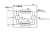
- the turbo decoder 50 includes element decoders 60 and 70, an interleaver 80, and a deinterleaver 90.
- the turbo decoder 50 decodes the encoded information bits based on the likelihood data y s , y p1 , y p2 .
- the likelihood data y s is an encoded sequence in which noise is added to the systematic bit sequence on the transmission path
- the likelihood data y p1 is an encoded sequence in which noise is added to the parity bit sequence 1 on the transmission path. It is.
- the likelihood data yp2 is an encoded sequence in which noise is added to the parity bit sequence 1.
- the interleaver 80 is an interleaver that performs replacement in the same order as the interleaver 40 shown in FIG.
- the deinterleaver 90 is an interleaver that returns the information bits replaced by the interleaver 80 to the original order.
- the element decoders 60 and 70 are decoders that determine posterior probabilities using, for example, MAP decoding (Maximum A Posteriori Probability decoding) or SOVA (Soft Output Viterbi Algorithm). It is.
- the element decoder 60 repeatedly performs error correction decoding of the likelihood data y s using the redundant bits of the likelihood data y p1 and the posterior probability obtained by the element decoder 70 to obtain the posterior probability.
- the element decoder 60 outputs the obtained posterior probability to the element decoder 70 via the interleaver 80.
- the element decoder 70 repeatedly performs error correction decoding of the likelihood data y s using the redundant bits of the likelihood data y p2 and the posterior probability obtained by the element decoder 60 to obtain the posterior probability.
- the element decoder 70 outputs the obtained posterior probability to the element decoder 60 via the deinterleaver 90. Further, the posterior probability obtained by the element decoder 70 becomes the decoded information bit.
- the element decoders 60 and 70 repeatedly perform error correction decoding, thereby improving error correction capability.
- the QPSK (four-phase transition modulation) method is a modulation method in which the amplitude is fixed and 2-bit information is assigned to four phases.
- FIG. 14 is a diagram for explaining the QPSK method.
- the vertical axis is an imaginary axis
- the horizontal axis is a real number axis.
- Each bit pattern (00, 10, 11, 01) is represented by a symbol represented by a specific phase.
- the reliability of 2 bits (the first bit and the second bit) is the same.
- multi-level modulation is a modulation scheme that transmits an amount of information higher than the QPSK scheme by assigning each binary bit a combination of different amplitudes and different phases.
- FIG. 15 is a diagram for explaining 16QAM, which is an example of a multi-level modulation method.
- the vertical axis is an imaginary axis
- the horizontal axis is a real axis.
- 16QAM 4-bit information is assigned to each combination of four amplitudes and four phases.
- 16QAM has 16 symbols.
- the reliability of 4 bits (the 1st bit, the 2nd bit, the 3rd bit, and the 4th bit) is not all the same, and bias occurs. Specifically, the reliability of the first bit and the third bit is different, and the reliability of the second bit and the fourth bit are different.
- the gradation modulation method is a method of assigning information bits assigned to one symbol to different users in multilevel modulation. For example, among the 4 bits assigned to one symbol, the first bit is assigned to user A, the second bit is assigned to user B, the third bit is assigned to user C, and the fourth bit is assigned to user D.
- FIG. 16 is a diagram for explaining the gradation modulation method.
- the bandwidth B is divided into a plurality of resource blocks (RB), and symbols are allocated to a part of the resource blocks. Then, one bit among the information bits corresponding to the symbol is assigned to the user. For example, in FIG. 16, when RB0 and RB1 are assigned to user A, the first bit of the bit strings of the symbols of RB0 and RB1 is the bit assigned to user A.
- FIG. 17 is a diagram illustrating fading of radio waves transmitted to user A and fading of radio waves transmitted to user B.
- BICM Bit Interleaved coded modulation
- MLC Multi Level Coding
- FIG. 18 is a diagram showing a configuration of a BICM transmitter.
- the transmitter 100 includes an encoding unit 101 that encodes information bits, similarly to the turbo encoder.
- it includes a channel interleaver 102 that rearranges the order of encoded information bits, and a modulation unit 103 that performs multilevel modulation or hierarchical modulation.
- FIG. 19 is a diagram illustrating a configuration of an MLC transmitter.
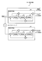
- the transmitter 110 includes a dividing unit 111, encoding units 112a and 112b, channel interleavers 113a and 113b, and a multilevel modulation unit 114.
- the dividing unit 111 is a processing unit that divides an information bit into two, outputs one divided information bit to the encoding unit 112a, and outputs the other information bit to the encoding unit 112b.
- Encoder 112a encodes information bits and outputs the encoded information bits to channel interleaver 113a.
- Encoding section 112b encodes information bits and outputs the encoded information bits to channel interleaver 113b.
- the channel interleaver 113a replaces the order of the encoded information bits, and outputs the replaced information bits to the multi-level modulation unit 114.
- Channel interleaver 113b replaces the order of the encoded information bits, and outputs the replaced information bits to multilevel modulation section 114.
- the multi-level modulation unit 114 assigns the information bits acquired from the interleave 113a to the first bit and the second bit (L0) and acquires them from the interleave 113b.
- the assigned information bits are assigned to the third bit and the fourth bit (L1). Then, the information bits are transmitted by modulating the signal to have an amplitude and phase corresponding to the assigned symbols.
- the coding rate of the information bits assigned to the levels L0 and L1 is determined by the encoding units 112a and 112b in consideration of the difference in transmission quality of the information bits assigned to the levels L0 and L1. By adjusting, the overall error rate specification is improved.
- MSD Multi Stage Decoding
- MSD is known as a means for decoding information bits encoded by the MLC method.
- the MLC method although the reliability can be made constant, even if the code length is small, the code needs to be divided into two or more.
- the turbo code has a characteristic that the characteristic is deteriorated when the code length is small. Therefore, the MLC method has a problem that the characteristic is deteriorated according to the code length. In addition, the MLC method is easily affected by deterioration in reliability of partial likelihood data in fading.
- the present invention has been made in order to solve the above-described problems of the prior art, and provides a transmission apparatus and the like that stabilize the reliability of each bit included in an information bit while suppressing characteristic deterioration. With the goal.
- the transmitting apparatus includes a first element encoder that encodes information bits to generate a first parity bit sequence, and an information bit in which a bit string is replaced
- a second element encoder that generates a second parity bit sequence by encoding the information, generates information obtained by combining a part of the information bits and the first parity bit sequence, and a bit size of the generated information
- a first rate matching unit that adjusts, a second rate matching unit that generates information by combining a part of the information bits and the second parity bit sequence, and adjusts the bit size of the generated information
- a bit string combining information output from the first rate matching unit and information output from the second rate matching unit is generated, and a multi-value variable is generated based on the bit string. Having a multi-level modulator for the execution and requirements.
- this transmission apparatus it is possible to equalize the reliability of each bit included in the information bits while suppressing characteristic deterioration.
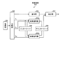
- FIG. 1 is a diagram illustrating the configuration of the transmission apparatus according to the first embodiment.
- FIG. 2 is a diagram illustrating a structure of information output from the P / S conversion unit 124a.
- FIG. 3 is a diagram illustrating a structure of information output from the P / S conversion unit 124b.
- FIG. 4 is a diagram illustrating a structure of information with repetition added.
- FIG. 5 is a diagram illustrating a structure of information when puncturing is performed.
- FIG. 6 is a diagram of the configuration of the receiving apparatus according to the first embodiment.
- FIG. 7 is a diagram illustrating a processing procedure of the transmission apparatus according to the first embodiment.
- FIG. 8 is a diagram illustrating the configuration of the transmission apparatus according to the second embodiment.
- FIG. 1 is a diagram illustrating the configuration of the transmission apparatus according to the first embodiment.
- FIG. 2 is a diagram illustrating a structure of information output from the P / S conversion unit 124a.
- FIG. 3 is a diagram illustrating
- FIG. 9 is a diagram illustrating a structure of information output from the encoding unit.
- FIG. 10 is a diagram illustrating the configuration of the receiving apparatus according to the second embodiment.
- FIG. 11 is a diagram for explaining other processes of the multi-level modulation unit.
- FIG. 12 is a diagram for explaining an example of a conventional turbo encoder.
- FIG. 13 is a diagram for explaining an example of a conventional turbo decoder.
- FIG. 14 is a diagram for explaining the QPSK method.
- FIG. 15 is a diagram for explaining 16QAM, which is an example of a multi-level modulation method.
- FIG. 16 is a diagram for explaining the gradation modulation method.
- FIG. 17 is a diagram illustrating fading of radio waves transmitted to user A and fading of radio waves transmitted to user B.
- FIG. 18 is a diagram illustrating a configuration of a BICM transmitter.
- FIG. 19 is a diagram illustrating a configuration of an MLC transmitter.
- FIG. 1 is a diagram illustrating the configuration of the transmission apparatus according to the first embodiment.
- the transmission device 120 includes a control unit 120a, an interleaver 121, element encoders 122a and 122b, a distribution switch 123, P / S conversion units 124a and 124b, channel interleavers 125a and 125b, and rate matching. Sections 126a and 126b, and a multi-level modulation section 127.
- the control unit 120a Based on the size K of information bits, the number N of code bits corresponding to the number of encoded information bits, and the coding rate R0 of the rate matching 126a, the control unit 120a distributes the information bit size K0 distributed by the distribution switch. , K1, and rate matching 126b coding rate R1 is calculated. It is assumed that the information bit size K, the number of code bits N, and the coding rate R0 are stored in advance in the control unit 120a.
- the control unit 120a outputs the information bit sizes K0 and K1 to the distribution switch 123. Also, the control unit 120a outputs the coding rate R0 to the rate matching unit 126a, and outputs the coding rate R1 to the rate matching unit 126b.
- the interleaver 121 is a processing unit that replaces the order of information bits when information bits are acquired. Interleaver 121 outputs the replaced information bits to element encoder 122b.
- the element encoder 122a is an encoder that performs feedback type convolutional coding and outputs a parity bit sequence 1 in the same manner as the element encoder 20 shown in FIG. 12 when information bits are acquired.
- the element encoder 122a When the element encoder 122a acquires the information bits whose order has been replaced by the interleaver 121, the element encoder 122a performs feedback type convolutional coding in the same manner as the element encoder 30 shown in FIG. Is an encoder that outputs.
- the distribution switch 123 acquires the information bit sizes K0 and K1 from the control unit 120a, outputs the information bits of the size K0 out of all the information bit sizes acquired from the outside to the P / S conversion unit 124a, and outputs the size K1. Is a switch that outputs the information bits to the P / S converter 124b.
- the P / S converter 124a combines the parity bit sequence 1 acquired from the element encoder 122a and the information bit of size K0 acquired from the distribution switch 123, and outputs the combined information to the channel interleaver 125a. It is.
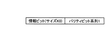
- FIG. 2 is a diagram illustrating a structure of information output from the P / S conversion unit 124a.
- the P / S converter 124b combines the parity bit sequence 2 acquired from the element encoder 122b and the information bit of size K1 acquired from the distribution switch 123, and outputs the combined information to the channel interleaver 125b. It is.
- FIG. 3 is a diagram illustrating a structure of information output from the P / S conversion unit 124b.
- the channel interleaver 125a is a processing unit that, when acquiring information obtained by combining information bits and the parity bit sequence 1, divides the acquired information into a plurality of data units and rearranges these data units according to a predetermined rule.
- the channel interleaver 125a outputs the rearranged information to the rate matching unit 126a.
- the channel interleaver 125b is a processing unit that divides the acquired information into a plurality of data units and rearranges these data units according to a predetermined rule when information obtained by combining information bits and the parity bit sequence 2 is acquired. .
- Channel interleaver 125b outputs the rearranged information to rate matching unit 126a.
- the rate matching unit 126a is a processing unit that calculates the bit size of the physical channel based on the coding rate R0 and adjusts the size of the information acquired from the channel interleaver 125a so as to correspond to the calculated bit size. .
- the bit size of the physical channel is K0 + K. K0 is calculated by the above-described equation (1).
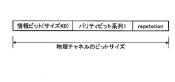
- FIG. 4 is a diagram showing the structure of information when repetition is added.
- FIG. 5 is a diagram illustrating a structure of information when puncturing is performed.
- the rate matching unit 126a outputs the information whose size has been adjusted to the multi-level modulation unit 127.
- the rate matching unit 126b is a processing unit that calculates the bit size of the physical channel based on the coding rate R1, and adjusts the size of the information acquired from the channel interleaver 125b so as to correspond to the calculated bit size. .
- the bit size of the physical channel is K1 + K.
- the multi-level modulation unit 127 is a processing unit that sequentially extracts a total of 4 bits by 2 bits from information acquired from the rate matching units 126a and 126b, maps symbols corresponding to the extracted 4 bits, and transmits information bits. .
- the multi-level modulation unit 127 associates the 2-bit information extracted from the information of the rate matching unit 126a with the first bit and the second bit (L0) of the four bits constituting the symbol. In addition, the multi-level modulation unit 127 associates the 2-bit information extracted from the information of the rate matching unit 126b with the 3rd bit and the 4th bit (L1) of the 4 bits constituting the symbol.
- the multi-level modulation unit 127 has the case where the 2-bit information extracted from the information of the rate matching unit 126a is “01” and the 2-bit information extracted from the information of the rate matching unit 126b is “10”. The symbol corresponding to the upper right of the fourth quadrant in FIG. 15 is mapped.
- the transmission apparatus 120 divides the information bits, calculates the parity bit sequences 1 and 2 from the divided information bits, and prevents the calculated parity bit sequence 1 and the parity bit sequence 2 from being added to the same information bit. Are combined with information bits (encoded information bits). Then, the transmission apparatus 120 replaces the order of the combined information and distributes the replaced information to the levels L0 and L1 to perform multilevel modulation, so that the influence of noise during transmission is determined for each bit of the information bits. The reliability of each bit included in the information bits is made constant.
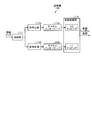
- FIG. 6 is a diagram illustrating a configuration of the receiving device 130 according to the first embodiment.
- the reception device 130 includes a demodulation unit 131, a distribution unit 132, element decoders 133a and 133b, an interleaver 134, and a deinterleaver 135.
- the demodulation unit 131 is a processing unit that acquires the modulated information from the transmission device 120 and demodulates the acquired information. Demodulation section 131 outputs the demodulated information to distribution section 132.
- the distribution unit 132 When the distribution unit 132 acquires information from the demodulation unit 131, the distribution unit 132 extracts likelihood data y s , y p1 , and y p2 from the acquired information. Distribution section 132 then outputs likelihood data y s to element decoder 133a and interleaver 134, and outputs likelihood data y p1 to element decoder 133a. Distribution section 132 outputs likelihood data yp2 to element decoder 133b.
- the element decoders 133a and 133b are decoders that obtain the posterior probabilities by, for example, MAP decoding or SOVA soft output decoding algorithm in the same manner as the element decoders 60 and 70 shown in FIG.
- the element decoder 133a repeatedly performs error correction decoding on the likelihood data y s by using the redundant bits of the likelihood data y p1 and the posterior probability obtained by the element decoder 70 to obtain the posterior probability.
- the element decoder 60 outputs the obtained posterior probability to the element decoder 133b via the interleaver 134.
- the element decoder 133b repeatedly performs error correction decoding of the likelihood data y s by using the redundant bits of the likelihood data y p2 and the posterior probability obtained by the element decoder 60, and obtains the posterior probability.
- the element decoder 133b outputs the obtained posterior probability to the element decoder 133a via the deinterleaver 135. Further, the posterior probability obtained by the element decoder 133b becomes the decoded information bit.
- element decoders 133a and 133b repeatedly perform error correction decoding, thereby improving error correction capability.
- the interleaver 134 is an interleaver that replaces the order of the likelihood data y s .
- the deinterleaver 135 is an interleaver that replaces the order of the bit sequence of the posterior probabilities so that the reverse order of the interleaver 134 is obtained.
- Receiving device 130 performs decoding processing first from the one with the lowest coding rate. For example, in FIG. 1, when the coding rate R0 of the rate matching unit 126a is lower than the coding rate R1 of the rate matching unit 126b, the likelihood data y p1 is more encoded than the likelihood data y p2. The conversion rate becomes low. In this case, the element decoder 133a executes the decoding process first, and then the element decoder 133b executes the decoding process. The information of the coding rates R0 and R1 may be held in advance by the element decoders 133a and 133b.
- FIG. 7 is a diagram illustrating a processing procedure of the transmission apparatus according to the first embodiment.
- the control unit 120a obtains the information bit size K, the number N of coded bits, and the coding rate R0 (step S101), and the divided information bit sizes K0 and K1, and the coding.
- the rate R1 is calculated (step S102).
- Element encoders 122a and 122b generate parity bit sequences 1 and 2 (step S103), and P / S converters 124a and 124b combine information bits (systematic bit sequences) and parity bit sequences (step S104). .
- the channel interleavers 125a and 125b replace the arrangement order of the bit strings (step S105), and the rate matching unit 126a adjusts the bit size based on the coding rate (step S106). Then, the multi-level modulation unit 127 performs modulation based on the information acquired from the rate matching units 126a and 126b (step S107).
- the transmission apparatus 120 divides information bits, calculates parity bit sequences 1 and 2 from the divided information bits, and the calculated parity bit sequence 1 and parity bit sequence 2 are It is combined with information bits (encoded information bits) so as not to be added to the same information bits. Then, the transmission apparatus 120 replaces the order of the combined information and distributes the replaced information to the levels L0 and L1 to perform multilevel modulation, so that the influence of noise during transmission is determined for each bit of the information bits. And the reliability of each bit included in the information bits is made equal.
- the modulation scheme is described as a multi-level modulation scheme as an example.
- the modulation scheme is not limited to the multi-level modulation, and the hierarchical modulation scheme described in FIG. 16 is used. May be used.
- FIG. 8 is a diagram illustrating the configuration of the transmission apparatus according to the second embodiment.
- the transmission apparatus 200 includes a control unit 200a, an interleaver 201, element encoders 202a and 202b, a distribution switch 203, P / S conversion units 204a and 204b, channel interleavers 205a, 205b, and 209, Rate matching units 206 a, 206 b, 210, a dividing unit 207, a coding unit 208, and a multilevel modulation unit 211 are included.
- interleaver 201 the element encoders 202a and 202b, the distribution switch 203, the P / S converters 204a and 204b, the channel interleavers 205a and 205b, and the rate matching units 206a and 206b is described in the control shown in FIG. Unit 120a, interleaver 121, element encoders 122a and 122b, distribution switch 123, P / S converters 124a and 124b, channel interleavers 125a and 125b, and rate matching unit 126a.
- the dividing unit 207 is a processing unit that divides information bits based on a preset ratio.
- the dividing unit 207 outputs one divided information bit to the encoding unit 208, and outputs the other information bit to the interleaver 201, the element encoder 202a, and the distribution switch 203.
- the encoding unit 208 is a processing unit that generates a parity bit by encoding the acquired information bit when the information bit is acquired.
- the encoding unit 208 outputs information obtained by combining the information bits and the parity bits to the channel interleaver 209.
- FIG. 9 is a diagram illustrating a structure of information output from the encoding unit 208.
- the channel interleaver 209 is a processing unit that, when acquiring information in which information bits and parity bits are combined, divides the acquired information into a plurality of data units and rearranges these data units according to a predetermined rule.
- Channel interleaver 210 outputs the rearranged information to rate matching section 210.
- the rate matching unit 210 is a processing unit that adjusts the size of information acquired from the channel interleaver 125a so as to correspond to a preset bit size.
- the rate matching unit 210 outputs the size-adjusted information to the multi-level modulation unit 211.
- the multi-level modulation unit 211 is a processing unit that transmits information bits based on information acquired from the rate matching units 126a, 126b, and 210.
- the multi-level modulation unit 211 combines the information acquired from the rate matching unit 206a and the information acquired from the rate matching unit 210, and sequentially extracts 2-bit information from the combined information.
- the multi-level modulation unit 211 sequentially extracts 2 bits at a time from the information acquired from the rate matching unit 126b.
- the multilevel modulation unit 211 maps symbols corresponding to the extracted 4 bits and transmits information bits.
- the multi-level modulation unit 211 converts the 2-bit information extracted from the information obtained by combining the information of the rate matching unit 126a and the information of the rate matching 210 into the first bit and the second bit (L0) of the four bits constituting the symbol. ).
- the multi-level modulation unit 127 associates the 2-bit information extracted from the information of the rate matching unit 126b with the 3rd bit and the 4th bit (L1) of the 4 bits constituting the symbol.
- FIG. 10 is a diagram illustrating the configuration of the receiving device 300 according to the second embodiment.
- the reception apparatus 300 includes a demodulation unit 301, a distribution unit 302, element decoders 303a and 303b, an interleaver 304, a deinterleaver 305, a decoding unit 306, and a combining unit 307.
- the demodulator 301, the element decoders 303a and 303b, the interleaver 304, and the deinterleaver 305 are respectively the demodulator 131, the element decoders 133a and 133b, the interleaver 134, and the deinterleaver 135 shown in FIG. The same.
- Distribution section 302 When the distribution unit 302 acquires information from the demodulation unit 131, the distribution unit 302 uses the acquired information (including noise during transmission) and likelihood data y s , y p1 , y p2 from the acquired information. Extract. Distribution section 302 outputs the information generated by encoding section 203 to decoding section 306. Further, distribution section 302 outputs likelihood data y s to element decoder 303a and interleaver 304, and outputs likelihood data y p1 to element decoder 303a. Distribution section 302 also outputs likelihood data yp2 to element decoder 303b.
- the decoding unit 306 When the decoding unit 306 acquires information from the distribution unit 302, the decoding unit 306 performs error correction decoding of the information bits based on the parity bits of the acquired information, and outputs the decoded information bits to the combining unit 307.
- the combining unit 307 is a processing unit that combines the information bits acquired from the deinterleaver 305 and the information bits acquired from the decoding unit 306. The information bits combined by the combining unit 307 become information bits after decoding.
- the transmitting apparatus 200 divides the information bits, performs encoding different from that of the first embodiment on one of the divided information bits, and performs the other information bit.
- the reliability of each bit included in the information bits after transmission is made constant.
- the multilevel modulation unit 11 distributes the information acquired from the rate matching units 206a, 206b, and 210 to the two levels L0 and L1, and executes symbol mapping. It is not limited. For example, the information acquired from each rate matching unit 206a, 206b, 210 may be distributed to three levels L0, L1, and L2.
- the multi-level modulation unit 211 sequentially extracts 1-bit information from the information of the rate matching unit 210, and the extracted 1-bit information corresponds to the first bit (L0) of the 4 bits constituting the symbol.
- 1-bit information is sequentially extracted from the information of the rate matching unit 126a, and the extracted 1-bit information is made to correspond to the second bit (L1) of the 4 bits constituting the symbol.
- 2-bit information is sequentially extracted from the information of the rate matching unit 126b, and the extracted 2-bit information is made to correspond to the third and fourth bits (L2) of the four bits constituting the symbol.
- the multilevel modulation unit 211 may divide the information acquired from the rate matching unit 206b, divide the information acquired from the rate matching unit 206b, and perform modulation after combining the divided pieces of information.
- FIG. 11 is a diagram for explaining other processing of the multi-level modulation unit 211.
- information A is information acquired from the rate matching unit 206a
- information B is information acquired from the rate matching unit 206b.
- Multilevel modulation section 211 divides information A into information A1 and A2, and divides information B into information B1 and information B2.
- the multi-level modulation unit 211 generates information C that combines information A1 and information B1, and generates information D that combines information B2 and information A2.
- Multilevel modulation section 211 sequentially extracts a total of 4 bits from information C and D, 2 bits at a time, maps symbols corresponding to the extracted 4 bits, and transmits information bits.
- the multi-level modulation unit 211 associates the 2-bit information extracted from the information C with the first and second bits (L0) of the four bits constituting the symbol. Further, the multi-level modulation unit 211 associates the 2-bit information extracted from the information D with the third bit and the fourth bit (L1) of the four bits constituting the symbol.
- each component of each illustrated apparatus is functionally conceptual and does not necessarily need to be physically configured as illustrated.
- the specific form of distribution / integration of each device is not limited to that shown in the figure, and all or a part thereof may be functionally or physically distributed or arbitrarily distributed in arbitrary units according to various loads or usage conditions. Can be integrated and configured.
Landscapes
- Engineering & Computer Science (AREA)
- Computer Networks & Wireless Communication (AREA)
- Signal Processing (AREA)
- Error Detection And Correction (AREA)
- Detection And Prevention Of Errors In Transmission (AREA)
Abstract
本発明にかかる送信装置(120)は、情報ビットを分割し、分割した情報ビットからパリティビット系列1、2を算出し、算出したパリティビット系列1とパリティビット系列2が同一の情報ビットに付加されないように情報ビット(符号化された情報ビット)と結合する。そして、本発明にかかる送信装置(120)は、結合した情報の順序を置換すると共に、置換した情報を各レベルL0,L1に分配して多値変調を実行することで、各ビットの信頼度を一定化する。
Description
本発明は、情報ビットの符号化および変調を行う送信装置等に関する。
近年、送信機が受信機に情報ビットを伝送する場合には、情報ビットに対して符号化および変調を行った後に、無線チャンネルを通して伝送する。情報ビットを符号化する符号化方法として、ターボ符号がある。また、情報ビットを変調する変調方法として、多値変調、階層変調などがある。以下において、ターボ符号、多値変調、階層変調について説明する。
ターボ符号は、複数の要素符号とインターリーバを組合せた符号化方法である。ここでは、3GPP(3rd Generation Partnership Project)で標準化されているターボ符号を例に説明する。図12は、従来のターボ符号器の一例を説明するための図である。
図12に示すように、ターボ符号器10は、要素符号器20、30とインターリーバ40を有する。要素符号器20は、遅延器21~23を有し、要素符号器30は、遅延器31~33を有する。要素符号器20に、情報ビットをそのまま入力することで、帰還型の畳み込み符号化が行われ、パリティビット系列1が生成される。
一方、要素符号器30に入力する情報ビットは、インターリーバ40により、ビット列の順序が置換される。要素符号器20に、ビット列の順序が置換された情報ビットを入力することで、帰還型の畳み込み符号化が行われ、パリティビット系列2が生成される。
そして、ターボ符号器10は、情報ビットに対応する組織ビット系列と、パリティビット系列1と、パリティビット系列2をシリアルに結合したビット列を出力する。
続いて、ターボ符号器10により符号化された情報ビットを復号化する処理について説明する。図13は、従来のターボ復号器の一例を説明するための図である。図13に示すように、ターボ復号器50は、要素復号器60,70、インターリーバ80、デインターリーバ90を有する。
ターボ復号器50は、尤度データys,yp1,yp2を基にして、符号化された情報ビットを復号化する。尤度データysは、伝送路上で、組織ビット系列に雑音が付加された符号化系列であり、尤度データyp1は、伝送路上で、パリティビット系列1に雑音が付加された符号化系列である。また、尤度データyp2は、パリティビット系列1に雑音が付加された符号化系列である。
インターリーバ80は、図12に示したインターリーバ40と同じ順序の置換を行うインターリーバである。デインターリーバ90は、インターリーバ80で置換された情報ビットを元の順序に戻すインターリーバである。
要素復号器60,70は、例えば、MAP復号(Maximum A Posteriori Probability decoding;最大事後確率復号)や、SOVA(Soft Output Viterbi Algorithm;軟出力ビタビアリゴリズム)の軟出力復号アルゴリズムにより事後確率を求める復号器である。
要素復号器60は、尤度データyp1の冗長ビットと、要素復号器70により求められた事後確率を利用して、尤度データysの誤り訂正復号を繰り返し実行し、事後確率を求める。要素復号器60は求めた事後確率を、インターリーバ80を介して要素復号器70に出力する。
要素復号器70は、尤度データyp2の冗長ビットと、要素復号器60により求められた事後確率を利用して、尤度データysの誤り訂正復号を繰り返し実行し、事後確率を求める。要素復号器70は求めた事後確率を、デインターリーバ90を介して要素復号器60に出力する。また、要素復号器70の求めた事後確率が、復号後の情報ビットとなる。ターボ復号では、要素復号器60,70が繰り返し、誤り訂正復号を実行することで、誤り訂正能力を高める。
ところで、信号の変調は、基準信号(ベースバンド)の位相や振幅を変調することで、情報ビットを伝送する。例えば、QPSK(四位相遷移変調)方式は、振幅を固定し、2ビットの情報を4つの位相に割当てる変調方式である。図14は、QPSK方式を説明するための図である。図14において縦軸が虚数の軸であり、横軸が実数の軸である。各ビットパターン(00、10、11、01)は、特定の位相によって表現される、シンボルで表す。QPSK方式は、4個のシンボルが存在する。振幅を固定するQPSK方式では、2ビット(1ビット目と2ビット目)の信頼度は同じとなる。
一方、多値変調は、異なる振幅と異なる位相の組合せを各バイナリビットに割当てることで、QPSK方式以上の情報量を伝送する変調方式である。図15は、多値変調方式の一例である16QAMを説明するための図である。図15において縦軸が虚数の軸であり、横軸が実数の軸である。図15に示すように、16QAMでは、4ビットの情報を、4つの振幅と4つの位相の各組合せに割当てる。16QAMは、16個のシンボルが存在する。16QAMは、4ビット(1ビット目、2ビット目、3ビット目、4ビット目)の信頼度は全てが同じとはならず偏りが生じる。具体的には、1ビット目と3ビット目の信頼度が異なり、2ビット目と4ビット目の信頼度が異なる。
続いて、階調化変調方式は、多値変調において、1つのシンボルに割当てられた情報ビットを異なるユーザに割当てる方式である。例えば、1つのシンボルに割当てられた4ビットのうち、1ビット目をユーザAに割り当て、2ビット目をユーザBに割り当て、3ビット目をユーザCに割り当て、4ビット目をユーザDに割当てる。
図16は、階調化変調方式を説明するための図である。図16に示すように、階調化変調方式では、帯域幅Bを複数のリソースブロック(RB)に分割し、リソースブロックの一部にシンボルを割当てる。そして、シンボルに対応する情報ビット中の1ビットを該当ユーザに割当てるビットとする。例えば、図16において、RB0、RB1をユーザAに割当てた場合、RB0、RB1の各シンボルのビット列のうち、1ビット目がユーザAに割当てられたビットとなる。図17は、ユーザAに送信される電波のフェージングとユーザBに送信される電波のフェージングを示す図である。
このように、1つのシンボルに割当てられた情報ビットを、単一のユーザに割当てるよりも、1つのシンボルを複数のユーザに割当てることで、よりフレキシブルなスケジューリングを行う。また、シンボルに含まれる情報ビットを各ユーザに割り振ることで、図17に示すように、変動する信頼度の影響を各ユーザで平均化し、全体としてのスループットを向上させる。
上述した符号方式と変調方式を組合せる伝送方式として、例えば、BICM(Bit Interleaved coded modulation)、MLC(Multi Level Coding)が存在する。
図18は、BICM方式の送信機の構成を示す図である。図18に示すように、この送信機100は、ターボ符号器と同様に、情報ビットの符号化を行う符号化部101を有する。また、符号化された情報ビットの順序を並べ替えるチャネルインターリーバ102、多値変調または階層化変調を行う変調部103を有する。
一方、MLC方式の送信機は、情報ビットを分割し、分割した各情報ビットを符号化し、多値変調を行う。図19は、MLC方式の送信機の構成を示す図である。図19に示すように、この送信機110は、分割部111、符号化部112a,112b、チャネルインターリーバ113a,113b、多値変調部114を有する。
分割部111は、情報ビットを2分割し、分割した一方の情報ビットを符号化部112aに出力し、もう一方の情報ビットを符号化部112bに出力する処理部である。
符号化部112aは、情報ビットを符号化し、符号化した情報ビットをチャネルインターリーバ113aに出力する。符号化部112bは、情報ビットを符号化し、符号化した情報ビットをチャネルインターリーバ113bに出力する。
チャネルインターリーバ113aは、符号化された情報ビットの順序を置換し、置換した情報ビットを多値変調部114に出力する。チャネルインターリーバ113bは、符号化された情報ビットの順序を置換し、置換した情報ビットを多値変調部114に出力する。
多値変調部114は、図15に示したように4ビット毎にシンボルを割当てる場合に、インターリーブ113aから取得した情報ビットを、1ビット目、2ビット目(L0)に割り当て、インターリーブ113bから取得した情報ビットを3ビット目、4ビット目(L1)に割当てる。そして、割当てたシンボルに応じた振幅、位相に信号を変調することで、情報ビットを伝送する。
MLC方式の送信機では、各レベルL0、L1に割当てられた情報ビットの伝送品質の違いを考慮して、各レベルL0、L1に割当てる情報ビットの符号化率を、符号化部112a、112bで調整することで、全体の誤り率特定を改善する。なお、MLC方式により符号化された情報ビットを復号化するものとして、MSD(Multi Stage Decoding )が知られている。
3GPP TS 36.212 v8.5.0(2008-12)
U.Wachsmann,J.Huber,"Power and bandwidth Efficient digital communication using turbo codes in multilevel codes",European Transactions on Telecommunications Vol.6,No.5,pp557-567
しかしながら、ターボ符号と多値変調を組合せて用いる伝送方式では、シンボルに割当てた各ビットの信頼度に偏りが生じるため、情報ビットに含まれる各ビットの信頼度が一定とはならず、信頼度が混合した情報ビットを復号器に入力されてしまうという問題があった。信頼度の偏った情報ビットを復号化する場合と、信頼度が一定となる情報ビットを復号化する場合を比較すると、信頼度の偏った情報ビットを復号化するほうが、復号化の効率が悪くなる。
なお、MLC方式では、信頼度を一定にすることができるものの、符号長が小さい場合であっても、符号を二つ以上に分割する必要がある。ターボ符号では、符号長が小さいと特性が劣化する特徴があるので、MLC方式では、符号長に応じて特性が劣化してしまうという問題がある。また、MLC方式では、フェージングにおける、一部尤度データの信頼度の劣化の影響を受けやすい。
そこで、この発明は、上述した従来技術の課題を解決するためになされたものであり、特性劣化を抑えつつ、情報ビットに含まれる各ビットの信頼度を一定化する送信装置等を提供することを目的とする。
上述した課題を解決し、目的を達成するために、この送信装置は、情報ビットの符号化を行い第1のパリティビット系列を生成する第1の要素符号器と、ビット列が置換された情報ビットの符号化を行い第2のパリティビット系列を生成する第2の要素符号器と、前記情報ビットの一部と前記第1のパリティビット系列を結合した情報を生成し、生成した情報のビットサイズを調整する第1のレートマッチング部と、前記情報ビットの一部と前記第2のパリティビット系列を結合した情報を生成し、生成した情報のビットサイズを調整する第2のレートマッチング部と、前記第1のレートマッチング部から出力される情報と、前記第2のレートマッチング部から出力される情報を組合せたビット列を生成し、当該ビット列に基づいて多値変調を実行する多値変調部を有することを要件とする。
この送信装置によれば、特性劣化を抑えつつ、情報ビットに含まれる各ビットの信頼度を均等化することが出来る。
以下に添付図面を参照して、この発明に係る送信装置、受信装置の実施例を詳細に説明する。
本実施例1にかかる送信装置の構成について説明する。図1は、本実施例1にかかる送信装置の構成を示す図である。図1に示すように、この送信装置120は、制御部120a、インターリーバ121、要素符号器122a,122b、分配スイッチ123、P/S変換部124a,124b、チャネルインターリーバ125a,125b、レートマッチング部126a,126b、多値変調部127を有する。
制御部120aは、情報ビットのサイズK、符号化された情報ビットの数に対応する符号ビット数N、レートマッチング126aの符号化率R0を基にして、分配スイッチが分配する情報ビットのサイズK0,K1、レートマッチング126bの符号化率R1を算出する。情報ビットのサイズK、符号ビット数N、符号化率R0は、制御部120aに予め格納されているものとする。
制御部120aが、情報ビットのサイズK0を算出する場合には、
K0=N×R0/2・・・(1)
により算出する。
K0=N×R0/2・・・(1)
により算出する。
制御部120aが、情報ビットのサイズK1を算出する場合には、
K1=K-K0・・・(2)
により算出する。
K1=K-K0・・・(2)
により算出する。
制御部120aが、レートマッチング126bの符号化率R1を算出する場合には、
R1=2×(K-K0)/N=2×R-R0・・・(3)
により算出する。
R1=2×(K-K0)/N=2×R-R0・・・(3)
により算出する。
制御部120aは、情報ビットのサイズK0,K1を分配スイッチ123に出力する。また、制御部120aは、符号化率R0をレートマッチング部126aに出力し、符号化率R1をレートマッチング部126bに出力する。
インターリーバ121は、情報ビットを取得した場合に、情報ビットの順序を置換する処理部である。インターリーバ121は、置換した情報ビットを要素符号器122bに出力する。
要素符号器122aは、情報ビットを取得した場合に、図12に示した要素符号器20と同様にして、帰還型の畳み込み符号化を行い、パリティビット系列1を出力する符号器である。
要素符号器122aは、インターリーバ121により順序を置換された情報ビットを取得した場合に、図12に示した要素符号器30と同様にして、帰還型の畳み込み符号化を行い、パリティビット系列2を出力する符号器である。
分配スイッチ123は、情報ビットのサイズK0,K1を制御部120aから取得し、外部から取得する情報ビットの全サイズのうち、サイズK0の情報ビットをP/S変換部124aに出力し、サイズK1の情報ビットをP/S変換部124bに出力するスイッチである。
P/S変換部124aは、要素符号器122aから取得するパリティビット系列1と、分配スイッチ123から取得するサイズK0の情報ビットとを結合し、結合した情報をチャンネルインターリーバ125aに出力する処理部である。図2は、P/S変換部124aが出力する情報の構造を示す図である。
P/S変換部124bは、要素符号器122bから取得するパリティビット系列2と、分配スイッチ123から取得するサイズK1の情報ビットとを結合し、結合した情報をチャンネルインターリーバ125bに出力する処理部である。図3は、P/S変換部124bが出力する情報の構造を示す図である。
チャネルインターリーバ125aは、情報ビットとパリティビット系列1が結合した情報を取得した場合に、取得した情報を複数のデータ単位に分割し、これらデータ単位を所定の規則に従って並び替える処理部である。チャネルインターリーバ125aは、並び替えた情報をレートマッチング部126aに出力する。
チャネルインターリーバ125bは、情報ビットとパリティビット系列2が結合した情報を取得した場合に、取得した情報を複数のデータ単位に分割し、これらデータ単位を所定の規則にしたがって並びかえる処理部である。チャネルインターリーバ125bは、並び替えた情報をレートマッチング部126aに出力する。
レートマッチング部126aは、符号化率R0に基づいて、物理チャネルのビットサイズを算出し、算出したビットサイズに対応するように、チャネルインターリーバ125aから取得した情報のサイズを調整する処理部である。物理チャネルのビットサイズは、K0+Kとなる。なお、K0は、上述した式(1)で算出する。
レートマッチング部126aは、チャネルインターリーバ125aから取得した情報のビットサイズが物理チャネルのビットサイズよりも小さい場合には、レペテション(repetetion)を情報に付加してビットサイズを合わせる。図4は、レペテションを付加した場合の情報の構造を示す図である。
一方、レートマッチング部126aは、チャネルインターリーバ125aから取得した情報のビットサイズが物理チャネルのビットサイズよりも大きい場合には、ビットサイズが合うように、情報の一部を削除するパンクチャリング(pancturing)を実行する。図5は、パンクチャリングを実行した場合の情報の構造を示す図である。レートマッチング部126aは、サイズを調整した情報を、多値変調部127に出力する。
レートマッチング部126bは、符号化率R1に基づいて、物理チャネルのビットサイズを算出し、算出したビットサイズに対応するように、チャネルインターリーバ125bから取得した情報のサイズを調整する処理部である。物理チャネルのビットサイズは、K1+Kとなる。なお、K0は、例えば、
K0=N×R1/2・・・(4)
により算出する。レートマッチング部126bは、サイズを調整した情報を、多値変調部127に出力する。
K0=N×R1/2・・・(4)
により算出する。レートマッチング部126bは、サイズを調整した情報を、多値変調部127に出力する。
多値変調部127は、レートマッチング部126a,126bから取得した情報から2ビットずつ計4ビットを順次抽出し、抽出した4ビットに対応するシンボルをマッピングし、情報ビットを伝送する処理部である。
多値変調部127は、レートマッチング部126aの情報から抽出した2ビットの情報を、シンボルを構成する4ビットの内、1ビット目と2ビット目(L0)に対応させる。また、多値変調部127は、レートマッチング部126bの情報から抽出した2ビットの情報を、シンボルを構成する4ビットの内、3ビット目と4ビット目(L1)に対応させる。
例えば、多値変調部127は、レートマッチング部126aの情報から抽出した2ビットの情報が「01」であり、レートマッチング部126bの情報から抽出した2ビットの情報が「10」の場合には、図15の第4象限の右上に該当するシンボルをマッピングする。
このように、送信装置120は、情報ビットを分割し、分割した情報ビットからパリティビット系列1、2を算出し、算出したパリティビット系列1とパリティビット系列2が同一の情報ビットに付加されないように情報ビット(符号化されて情報ビット)と結合する。そして、送信装置120は、結合した情報の順序を置換すると共に、置換した情報を各レベルL0,L1に分配して多値変調を実行するので、伝送時の雑音の影響を情報ビットの各ビットに同等に与え、情報ビットに含まれる各ビットの信頼度を一定にする。
次に、本実施例1にかかる受信装置の構成について説明する。図6は、本実施例1にかかる受信装置130の構成を示す図である。図6に示すように、この受信装置130は、復調部131、分配部132、要素復号器133a,133b、インターリーバ134、デインターリーバ135を有する。
復調部131は、送信装置120から変調された情報を取得し、取得した情報を復調する処理部である。復調部131は、復調した情報を、分配部132に出力する。
分配部132は、復調部131から情報を取得した場合に、取得した情報から尤度データys,yp1,yp2を抽出する。そして、分配部132は、尤度データysを要素復号器133a、インターリーバ134に出力し、尤度データyp1を要素復号器133aに出力する。また、分配部132は、尤度データyp2を要素復号器133bに出力する。
要素復号器133a,133bは、図13に示した要素復号器60,70と同様にして、例えば、MAP復号や、SOVAの軟出力復号アルゴリズムにより事後確率を求める復号器である。
要素復号器133aは、尤度データyp1の冗長ビットと、要素復号器70により求められた事後確率を利用して、尤度データysの誤り訂正復号を繰り返し実行し、事後確率を求める。要素復号器60は求めた事後確率を、インターリーバ134を介して要素復号器133bに出力する。
要素復号器133bは、尤度データyp2の冗長ビットと、要素復号器60により求められた事後確率を利用して、尤度データysの誤り訂正復号を繰り返し実行し、事後確率を求める。要素復号器133bは求めた事後確率を、デインターリーバ135を介して要素復号器133aに出力する。また、要素復号器133bの求めた事後確率が、復号後の情報ビットとなる。ターボ復号では、要素復号器133a,133bが繰り返し、誤り訂正復号を実行することで、誤り訂正能力を高める。
インターリーバ134は、尤度データysの順序の置換を行うインターリーバである。デインターリーバ135は、インターリーバ134に対して逆の順序となるように事後確率のビット列の順序を置換するインターリーバである。
なお、受信装置130は、符号化率の低いものから先に復号処理を行う。例えば、図1において、レートマッチング部126aの符号化率R0が、レートマッチング部126bの符号化率R1よりも低い場合には、尤度データyp2よりも尤度データyp1の方が、符号化率が低くなる。この場合、要素復号器133aが先に復号処理を実行し、次いで、要素復号器133bが復号処理を実行する。符号化率R0,R1の情報は、予め、要素復号器133a,133bが保持していても良い。
次に、本実施例1にかかる送信装置120の処理手順について説明する。図7は、本実施例1にかかる送信装置の処理手順を示す図である。図7に示すように、制御部120aは、情報ビットのサイズK、符号化ビットの数N、符号化率R0を取得し(ステップS101)、分割後の情報ビットのサイズK0,K1、符号化率R1を算出する(ステップS102)。
要素符号器122a,122bは、パリティビット系列1、2を生成し(ステップS103)、P/S変換部124a,124bが、情報ビット(組織ビット系列)とパリティビット系列を結合する(ステップS104)。
チャネルインターリーバ125a,125bが、ビット列の並び順を置換し(ステップS105)、レートマッチング部126aが、符号化率に基づいて、ビットサイズを調整する(ステップS106)。そして、多値変調部127が、レートマッチング部126a,126bから取得した情報に基づいて変調を行う(ステップS107)。
上述してきたように、本実施例1にかかる送信装置120は、情報ビットを分割し、分割した情報ビットからパリティビット系列1、2を算出し、算出したパリティビット系列1とパリティビット系列2が同一の情報ビットに付加されないように情報ビット(符号化されて情報ビット)と結合する。そして、送信装置120は、結合した情報の順序を置換すると共に、置換した情報を各レベルL0,L1に分配して多値変調を実行するので、伝送時の雑音の影響を情報ビットの各ビットに同等に与え、情報ビットに含まれる各ビットの信頼度を均等にする。
なお、本実施例1では一例として、変調方式を多値変調方式として説明を行ったが、変調方式は、多値変調に限定されるものではなく、図16にて説明した階層化変調方式を利用しても良い。
次に、本実施例2にかかる送信装置について説明する。図8は、本実施例2にかかる送信装置の構成を示す図である。図8に示すように、この送信装置200は、制御部200a、インターリーバ201、要素符号器202a,202b、分配スイッチ203、P/S変換部204a,204b、チャネルインターリーバ205a,205b,209、レートマッチング部206a,206b,210、分割部207、符号部208、多値変調部211を有する。
このうち、インターリーバ201、要素符号器202a,202b、分配スイッチ203、P/S変換部204a,204b、チャネルインターリーバ205a,205b、レートマッチング部206a,206bの説明は、図1に示した制御部120a、インターリーバ121、要素符号器122a,122b、分配スイッチ123、P/S変換部124a,124b、チャネルインターリーバ125a,125b、レートマッチング部126aとそれぞれ同じである。
分割部207は、予め設定された割合に基づいて情報ビットを分割する処理部である。分割部207は、分割した一方の情報ビットを符号部208に出力し、もう一方の情報ビットを、インターリーバ201、要素符号器202a、分配スイッチ203に出力する。
符号部208は、情報ビットを取得した場合に、取得した情報ビットを符号化することでパリティビットを生成する処理部である。符号部208は、情報ビットとパリティビットを結合した情報を、チャネルインターリーバ209に出力する。図9は、符号部208が出力する情報の構造を示す図である。
チャネルインターリーバ209は、情報ビットとパリティビットが結合した情報を取得した場合に、取得した情報を複数のデータ単位に分割し、これらデータ単位を所定の規則にしたがって並び替える処理部である。チャネルインターリーバ210は、並び替えた情報をレートマッチング部210に出力する。
レートマッチング部210は、予め設定されたビットサイズに対応するように、チャネルインターリーバ125aから取得した情報のサイズを調整する処理部である。レートマッチング部210は、サイズを調整した情報を、多値変調部211に出力する。
多値変調部211は、レートマッチング部126a,126b,210から取得した情報に基づいて、情報ビットを伝送する処理部である。多値変調部211は、レートマッチング部206aから取得した情報と、レートマッチング部210から取得した情報を結合し、結合した情報から2ビットの情報を順次抽出する。また、多値変調部211は、レートマッチング部126bから取得した情報から2ビットずつ順次抽出する。
多値変調部211は、4ビットの情報を抽出するたびに、抽出した4ビットに対応するシンボルをマッピングし、情報ビットを伝送する。多値変調部211は、レートマッチング部126aの情報とレートマッチング210の情報を結合した情報から抽出した2ビットの情報を、シンボルを構成する4ビットの内、1ビット目と2ビット目(L0)に対応させる。また、多値変調部127は、レートマッチング部126bの情報から抽出した2ビットの情報を、シンボルを構成する4ビットの内、3ビット目と4ビット目(L1)に対応させる。
次に、本実施例2にかかる受信装置の構成について説明する。図10は、本実施例2にかかる受信装置300の構成を示す図である。図10に示すように、この受信装置300は、復調部301、分配部302、要素復号器303a,303b、インターリーバ304、デインターリーバ305、復号部306、結合部307を有する。
このうち、復調部301、要素復号器303a,303b、インターリーバ304、デインターリーバ305は、図6に示した復調部131、要素復号器133a,133b、インターリーバ134、デインターリーバ135とそれぞれ同じである。
分配部302は、復調部131から情報を取得した場合に、取得した情報から、符号部208が生成した情報(伝送時の雑音も含む)と、尤度データys,yp1,yp2を抽出する。分配部302は、符号部203が生成した情報を、復号部306に出力する。また、分配部302は、尤度データysを要素復号器303a、インターリーバ304に出力し、尤度データyp1を要素復号器303aに出力する。また、分配部302は、尤度データyp2を要素復号器303bに出力する。
復号部306は、分配部302から情報を取得した場合に、取得した情報のパリティビットに基づいて、情報ビットの誤り訂正復号を実行し、復号した情報ビットを結合部307に出力する。
結合部307は、デインターリーバ305から取得する情報ビットと、復号部306から取得する情報ビットを結合する処理部である。結合部307が結合した情報ビットが、復号後の情報ビットとなる。
上述してきたように、本実施例2にかかる送信装置200は、情報ビットを分割し、分割した情報ビットの一方を、実施例1とは異なる符号化を行い、もう一方の情報ビットを、実施例1と同様の符号化を行うことで、伝送後の情報ビットに含まれる各ビットの信頼度を一定にする。
なお、本実施例2にかかる多値変調部11は、各レートマッチング部206a,206b,210から取得した情報を、2つのレベルL0、L1に振り分けてシンボルのマッピングを実行していたがこれに限定されるものではない。例えば、各レートマッチング部206a,206b,210から取得した情報を、3つのレベルL0、L1、L2に振り分けてもよい。
例えば、多値変調部211は、レートマッチング部210の情報から1ビットの情報を順次抽出し、抽出した1ビットの情報を、シンボルを構成する4ビットの内、1ビット目(L0)に対応させる。また、レートマッチング部126aの情報から1ビットの情報を順次抽出し、抽出した1ビットの情報を、シンボルを構成する4ビットの内、2ビット目(L1)に対応させる。また、レートマッチング部126bの情報から2ビットの情報を順次抽出し、抽出した2ビットの情報を、シンボルを構成する4ビットの内、3ビット目と4ビット目(L2)に対応させる。
また、多値変調部211は、レートマッチング部206bから取得する情報を分割すると共に、レートマッチング部206bから取得する情報を分割し、分割した各情報をそれぞれ組合せた後に、変調を行っても良い。図11は、多値変調部211のその他の処理を説明するための図である。
図11において、情報Aを、レートマッチング部206aから取得する情報とし、情報Bを、レートマッチング部206bから取得する情報とする。多値変調部211は、情報Aを情報A1,A2に分割し、情報Bを情報B1,情報B2に分割する。
そして、多値変調部211は、情報A1と情報B1を結合した情報Cを生成し、情報B2と情報A2を結合した情報Dを生成する。多値変調部211は、情報C,Dから2ビットずつ計4ビットを順次抽出し、抽出した4ビットに対応するシンボルをマッピングし、情報ビットを伝送する。
例えば、多値変調部211は、情報Cから抽出した2ビットの情報を、シンボルを構成する4ビットの内、1ビット目と2ビット目(L0)に対応させる。また、多値変調部211は、情報Dから抽出した2ビットの情報を、シンボルを構成する4ビットの内、3ビット目と4ビット目(L1)に対応させる。
ところで、本実施例において説明した各処理のうち、自動的におこなわれるものとして説明した処理の全部または一部を手動的におこなうこともでき、あるいは、手動的におこなわれるものとして説明した処理の全部または一部を公知の方法で自動的におこなうこともできる。この他、上記文書中や図面中で示した処理手順、制御手順、具体的名称、各種のデータやパラメータを含む情報については、特記する場合を除いて任意に変更することができる。
また、図示した各装置の各構成要素は機能概念的なものであり、必ずしも物理的に図示の如く構成されていることを要しない。すなわち、各装置の分散・統合の具体的形態は図示のものに限られず、その全部または一部を、各種の負荷や使用状況などに応じて、任意の単位で機能的または物理的に分散・統合して構成することができる。
10 ターボ符号器
20,30,122a,122b,133a,133b,202a,202b 要素符号器
21,22,23,31,32,33 遅延器
40,80,121,134,201,304 インターリーバ
60,70,303a,303b 要素復号器
90,135,305 デインターリーバ
100,110 送信機
101 符号化部
102,113a,113b,125a,125b,205a,205b,209 チャネルインターリーバ
103 変調部
111 分割部
112a,112b 符号化部
114,127,211 多値変調部
120,200 送信装置
120a,200 制御部
123 分配スイッチ
124a,124b,204a,204b P/S変換部
126a,126b,206a,206b,210 レートマッチング部
130 受信装置
131,301 復調部
132,302 分配部
207 分割部
208 符号部
20,30,122a,122b,133a,133b,202a,202b 要素符号器
21,22,23,31,32,33 遅延器
40,80,121,134,201,304 インターリーバ
60,70,303a,303b 要素復号器
90,135,305 デインターリーバ
100,110 送信機
101 符号化部
102,113a,113b,125a,125b,205a,205b,209 チャネルインターリーバ
103 変調部
111 分割部
112a,112b 符号化部
114,127,211 多値変調部
120,200 送信装置
120a,200 制御部
123 分配スイッチ
124a,124b,204a,204b P/S変換部
126a,126b,206a,206b,210 レートマッチング部
130 受信装置
131,301 復調部
132,302 分配部
207 分割部
208 符号部
Claims (5)
- 情報ビットの符号化を行い第1のパリティビット系列を生成する第1の要素符号器と、
ビット列が置換された情報ビットの符号化を行い第2のパリティビット系列を生成する第2の要素符号器と、
前記情報ビットの一部と前記第1のパリティビット系列を結合した情報を生成し、生成した情報のビットサイズを調整する第1のレートマッチング部と、
前記情報ビットの一部と前記第2のパリティビット系列を結合した情報を生成し、生成した情報のビットサイズを調整する第2のレートマッチング部と、
前記第1のレートマッチング部から出力される情報と、前記第2のレートマッチング部から出力される情報を組合せたビット列を生成し、当該ビット列に基づいて多値変調を実行する多値変調部
を有することを特徴とする送信装置。 - 多値変調部は、階層化変調方式に基づいて変調を実行することを特徴とする請求項1に記載の送信装置。
- 前記第1のレートマッチング部は、第1の符号化率に基づいてビットサイズを調整し、前記第2のレートマッチング部は、前記第1の符号化率に基づいて算出される第2の符号化率に基づいてビットサイズを調整することを特徴とする請求項1または2に記載の送信装置。
- 情報ビットを分割する分割部と、前記分割部が分割した情報ビットのうち、一部の情報ビットからパリティビットを生成する符号部と、前記一部の情報ビットと、前記符号部が生成したパリティビットとを結合した情報を生成し、生成した情報ビットサイズを調整する第3のレートマッチング部を有し、前記第1の要素符号器は、前記分割部が分割した情報ビットのうち、一部の情報ビットから第1のパリティビット系列を生成し、前記第2の要素符号器は、前記第1の要素符号器と等しい一部の情報ビットから第2のパリティビット系列を生成し、前記多値変調部は、前記第1、2、3のレートマッチング部から出力される情報を組合せたビット列を生成し、当該ビット列に基づいて多値変調を実行することを特徴とする請求項1または2に記載の送信装置。
- 第2の要素復号器の復号結果と、情報ビットに対応する第1の尤度データと、第1のパリティビット系列に対応する第2の尤度データを基にして、前記第1の尤度データの誤り訂正復号を繰り返し実行する第1の要素復号器と、
前記第1の要素復号器の復号結果と、情報ビットに対応する第1の尤度データと、第2のパリティビット系列に対応する第3の尤度データを基にして、前記第1の尤度データの誤り訂正復号を繰り返し実行する第2の要素復号器とを有し、
前記第1の要素復号器と前記第2の要素復号器は、請求項3に記載の第1の符号化率および第2の符号化率に基づいて復号を行う順序を特定することを特徴とする受信装置。
Priority Applications (3)
| Application Number | Priority Date | Filing Date | Title |
|---|---|---|---|
| JP2011519372A JP5472298B2 (ja) | 2009-06-18 | 2009-06-18 | 送信装置および受信装置 |
| PCT/JP2009/061126 WO2010146694A1 (ja) | 2009-06-18 | 2009-06-18 | 送信装置および受信装置 |
| US13/323,383 US20120084620A1 (en) | 2009-06-18 | 2011-12-12 | Transmission device and receiving device |
Applications Claiming Priority (1)
| Application Number | Priority Date | Filing Date | Title |
|---|---|---|---|
| PCT/JP2009/061126 WO2010146694A1 (ja) | 2009-06-18 | 2009-06-18 | 送信装置および受信装置 |
Related Child Applications (1)
| Application Number | Title | Priority Date | Filing Date |
|---|---|---|---|
| US13/323,383 Continuation US20120084620A1 (en) | 2009-06-18 | 2011-12-12 | Transmission device and receiving device |
Publications (1)
| Publication Number | Publication Date |
|---|---|
| WO2010146694A1 true WO2010146694A1 (ja) | 2010-12-23 |
Family
ID=43356032
Family Applications (1)
| Application Number | Title | Priority Date | Filing Date |
|---|---|---|---|
| PCT/JP2009/061126 Ceased WO2010146694A1 (ja) | 2009-06-18 | 2009-06-18 | 送信装置および受信装置 |
Country Status (3)
| Country | Link |
|---|---|
| US (1) | US20120084620A1 (ja) |
| JP (1) | JP5472298B2 (ja) |
| WO (1) | WO2010146694A1 (ja) |
Families Citing this family (3)
| Publication number | Priority date | Publication date | Assignee | Title |
|---|---|---|---|---|
| US9236977B2 (en) * | 2010-10-04 | 2016-01-12 | Qualcomm Incorporated | Method and apparatus for PUCCH and PUSCH encoding |
| KR102714110B1 (ko) * | 2016-09-07 | 2024-10-08 | 에스케이하이닉스 주식회사 | 메모리 컨트롤러, 반도체 메모리 시스템 및 그것의 동작 방법 |
| US20250112729A1 (en) * | 2023-10-02 | 2025-04-03 | Qualcomm Incorporated | Multi-level coding and bit-interleaved coded modulation |
Citations (3)
| Publication number | Priority date | Publication date | Assignee | Title |
|---|---|---|---|---|
| JP2002164948A (ja) * | 2000-09-14 | 2002-06-07 | Texas Instruments Inc | 高次変調シンボルマッピングにおける情報保護の優先度を決定するための方法および装置 |
| JP2005229319A (ja) * | 2004-02-12 | 2005-08-25 | Fujitsu Ltd | 送信装置、ビット配置方法 |
| WO2007029734A1 (ja) * | 2005-09-06 | 2007-03-15 | Kddi Corporation | データ伝送システム及びデータ伝送方法 |
Family Cites Families (3)
| Publication number | Priority date | Publication date | Assignee | Title |
|---|---|---|---|---|
| AU5333498A (en) * | 1997-12-24 | 1999-07-19 | Inmarsat Ltd | Coding method and apparatus |
| JP3810360B2 (ja) * | 2002-10-31 | 2006-08-16 | 三菱電機株式会社 | 変調装置及び変復調システム及び変調方法及び変調プログラム及び変調プログラムを記録したコンピュータ読み取り可能な記録媒体 |
| US8340006B2 (en) * | 2006-04-12 | 2012-12-25 | Panasonic Corporation | Transmission of multicast/broadcast services in a wireless communication network |
-
2009
- 2009-06-18 JP JP2011519372A patent/JP5472298B2/ja not_active Expired - Fee Related
- 2009-06-18 WO PCT/JP2009/061126 patent/WO2010146694A1/ja not_active Ceased
-
2011
- 2011-12-12 US US13/323,383 patent/US20120084620A1/en not_active Abandoned
Patent Citations (3)
| Publication number | Priority date | Publication date | Assignee | Title |
|---|---|---|---|---|
| JP2002164948A (ja) * | 2000-09-14 | 2002-06-07 | Texas Instruments Inc | 高次変調シンボルマッピングにおける情報保護の優先度を決定するための方法および装置 |
| JP2005229319A (ja) * | 2004-02-12 | 2005-08-25 | Fujitsu Ltd | 送信装置、ビット配置方法 |
| WO2007029734A1 (ja) * | 2005-09-06 | 2007-03-15 | Kddi Corporation | データ伝送システム及びデータ伝送方法 |
Also Published As
| Publication number | Publication date |
|---|---|
| US20120084620A1 (en) | 2012-04-05 |
| JPWO2010146694A1 (ja) | 2012-11-29 |
| JP5472298B2 (ja) | 2014-04-16 |
Similar Documents
| Publication | Publication Date | Title |
|---|---|---|
| AU751391B2 (en) | Coding and modulation method and apparatus for its implementation | |
| JP4522255B2 (ja) | 相補パターンマップ式畳込みコードを用いるデジタル音声放送方式及び装置 | |
| CA2556419C (en) | Method and apparatus for communications using turbo like codes | |
| RU2340092C2 (ru) | Устройство и способ передачи и приема закодированных данных посредством кодера, имеющего неравную вероятность ошибок, в системе мобильной связи | |
| JP2003244257A (ja) | 多値変調に適した符号語マッピング方法 | |
| KR101608573B1 (ko) | 무선 송수신기 디바이스, 통신 시스템, 및 그 디바이스 및 시스템에서 이용되는 채널 코딩 프로세싱 방법 | |
| JP4563456B2 (ja) | 送信装置、符号化装置及び復号装置 | |
| US9985746B2 (en) | Transmitter and receiver devices and methods thereof | |
| WO2003019792A1 (en) | System and method performing quadrature amplitude modulation by combining co-sets and strongly coded co-set identifiers | |
| KR20080100413A (ko) | 무선 채널을 통해 전송하는 비압축 비디오에 uep를적용하는 방법 및 시스템 | |
| CN101753268A (zh) | 无线通信装置的编码及调制方法、以及解码方法 | |
| JP4717072B2 (ja) | 送信装置 | |
| US9059829B2 (en) | Receiver and received signal decoding method | |
| KR20080111342A (ko) | 직교주파수분할다중접속방식의 이동 통신시스템에서 심볼전송 방법 및 장치 | |
| CN110199490A (zh) | 一种概率成形操作的方法和装置 | |
| JP2012515485A (ja) | 変調されたデータ・ストリームの送信方法および受信方法 | |
| JP5195989B2 (ja) | 送信方法 | |
| JP5472298B2 (ja) | 送信装置および受信装置 | |
| JP5153588B2 (ja) | 無線通信装置 | |
| CN102301604B (zh) | 无线通信装置 | |
| JP4841684B2 (ja) | 送信装置及び送信方法 | |
| Bota et al. | On the BER and spectral efficiency performances of coded QAM configurations that map non-coded bits | |
| Bo | Interleaver Design and Throughput Enhancement Technique | |
| Khalili | Design and Simulation of Coded-Modulation Using Turbo Trellis Coding and Multi-Layer Modulations |
Legal Events
| Date | Code | Title | Description |
|---|---|---|---|
| 121 | Ep: the epo has been informed by wipo that ep was designated in this application |
Ref document number: 09846187 Country of ref document: EP Kind code of ref document: A1 |
|
| WWE | Wipo information: entry into national phase |
Ref document number: 2011519372 Country of ref document: JP |
|
| NENP | Non-entry into the national phase |
Ref country code: DE |
|
| 122 | Ep: pct application non-entry in european phase |
Ref document number: 09846187 Country of ref document: EP Kind code of ref document: A1 |