WO2010146864A1 - 電磁クラッチ、圧縮機、電磁クラッチの製造方法 - Google Patents
電磁クラッチ、圧縮機、電磁クラッチの製造方法 Download PDFInfo
- Publication number
- WO2010146864A1 WO2010146864A1 PCT/JP2010/004049 JP2010004049W WO2010146864A1 WO 2010146864 A1 WO2010146864 A1 WO 2010146864A1 JP 2010004049 W JP2010004049 W JP 2010004049W WO 2010146864 A1 WO2010146864 A1 WO 2010146864A1
- Authority
- WO
- WIPO (PCT)
- Prior art keywords
- armature
- rotor
- contact surface
- electromagnetic clutch
- groove
- Prior art date
- Legal status (The legal status is an assumption and is not a legal conclusion. Google has not performed a legal analysis and makes no representation as to the accuracy of the status listed.)
- Ceased
Links
Images


Classifications
-
- F—MECHANICAL ENGINEERING; LIGHTING; HEATING; WEAPONS; BLASTING
- F16—ENGINEERING ELEMENTS AND UNITS; GENERAL MEASURES FOR PRODUCING AND MAINTAINING EFFECTIVE FUNCTIONING OF MACHINES OR INSTALLATIONS; THERMAL INSULATION IN GENERAL
- F16D—COUPLINGS FOR TRANSMITTING ROTATION; CLUTCHES; BRAKES
- F16D27/00—Magnetically- or electrically- actuated clutches; Control or electric circuits therefor
- F16D27/10—Magnetically- or electrically- actuated clutches; Control or electric circuits therefor with an electromagnet not rotating with a clutching member, i.e. without collecting rings
- F16D27/108—Magnetically- or electrically- actuated clutches; Control or electric circuits therefor with an electromagnet not rotating with a clutching member, i.e. without collecting rings with axially movable clutching members
- F16D27/112—Magnetically- or electrically- actuated clutches; Control or electric circuits therefor with an electromagnet not rotating with a clutching member, i.e. without collecting rings with axially movable clutching members with flat friction surfaces, e.g. discs
-
- F—MECHANICAL ENGINEERING; LIGHTING; HEATING; WEAPONS; BLASTING
- F04—POSITIVE - DISPLACEMENT MACHINES FOR LIQUIDS; PUMPS FOR LIQUIDS OR ELASTIC FLUIDS
- F04C—ROTARY-PISTON, OR OSCILLATING-PISTON, POSITIVE-DISPLACEMENT MACHINES FOR LIQUIDS; ROTARY-PISTON, OR OSCILLATING-PISTON, POSITIVE-DISPLACEMENT PUMPS
- F04C29/00—Component parts, details or accessories of pumps or pumping installations, not provided for in groups F04C18/00 - F04C28/00
- F04C29/0042—Driving elements, brakes, couplings, transmissions specially adapted for pumps
- F04C29/005—Means for transmitting movement from the prime mover to driven parts of the pump, e.g. clutches, couplings, transmissions
-
- F—MECHANICAL ENGINEERING; LIGHTING; HEATING; WEAPONS; BLASTING
- F16—ENGINEERING ELEMENTS AND UNITS; GENERAL MEASURES FOR PRODUCING AND MAINTAINING EFFECTIVE FUNCTIONING OF MACHINES OR INSTALLATIONS; THERMAL INSULATION IN GENERAL
- F16D—COUPLINGS FOR TRANSMITTING ROTATION; CLUTCHES; BRAKES
- F16D27/00—Magnetically- or electrically- actuated clutches; Control or electric circuits therefor
- F16D27/02—Magnetically- or electrically- actuated clutches; Control or electric circuits therefor with electromagnets incorporated in the clutch, i.e. with collecting rings
- F16D27/04—Magnetically- or electrically- actuated clutches; Control or electric circuits therefor with electromagnets incorporated in the clutch, i.e. with collecting rings with axially-movable friction surfaces
- F16D27/06—Magnetically- or electrically- actuated clutches; Control or electric circuits therefor with electromagnets incorporated in the clutch, i.e. with collecting rings with axially-movable friction surfaces with friction surfaces arranged within the flux
-
- F—MECHANICAL ENGINEERING; LIGHTING; HEATING; WEAPONS; BLASTING
- F04—POSITIVE - DISPLACEMENT MACHINES FOR LIQUIDS; PUMPS FOR LIQUIDS OR ELASTIC FLUIDS
- F04C—ROTARY-PISTON, OR OSCILLATING-PISTON, POSITIVE-DISPLACEMENT MACHINES FOR LIQUIDS; ROTARY-PISTON, OR OSCILLATING-PISTON, POSITIVE-DISPLACEMENT PUMPS
- F04C18/00—Rotary-piston pumps specially adapted for elastic fluids
- F04C18/02—Rotary-piston pumps specially adapted for elastic fluids of arcuate-engagement type, i.e. with circular translatory movement of co-operating members, each member having the same number of teeth or tooth-equivalents
- F04C18/0207—Rotary-piston pumps specially adapted for elastic fluids of arcuate-engagement type, i.e. with circular translatory movement of co-operating members, each member having the same number of teeth or tooth-equivalents both members having co-operating elements in spiral form
- F04C18/0215—Rotary-piston pumps specially adapted for elastic fluids of arcuate-engagement type, i.e. with circular translatory movement of co-operating members, each member having the same number of teeth or tooth-equivalents both members having co-operating elements in spiral form where only one member is moving
-
- F—MECHANICAL ENGINEERING; LIGHTING; HEATING; WEAPONS; BLASTING
- F16—ENGINEERING ELEMENTS AND UNITS; GENERAL MEASURES FOR PRODUCING AND MAINTAINING EFFECTIVE FUNCTIONING OF MACHINES OR INSTALLATIONS; THERMAL INSULATION IN GENERAL
- F16D—COUPLINGS FOR TRANSMITTING ROTATION; CLUTCHES; BRAKES
- F16D27/00—Magnetically- or electrically- actuated clutches; Control or electric circuits therefor
- F16D2027/008—Details relating to the magnetic circuit, or to the shape of the clutch parts to achieve a certain magnetic path
-
- F—MECHANICAL ENGINEERING; LIGHTING; HEATING; WEAPONS; BLASTING
- F16—ENGINEERING ELEMENTS AND UNITS; GENERAL MEASURES FOR PRODUCING AND MAINTAINING EFFECTIVE FUNCTIONING OF MACHINES OR INSTALLATIONS; THERMAL INSULATION IN GENERAL
- F16D—COUPLINGS FOR TRANSMITTING ROTATION; CLUTCHES; BRAKES
- F16D2300/00—Special features for couplings or clutches
- F16D2300/10—Surface characteristics; Details related to material surfaces
-
- Y—GENERAL TAGGING OF NEW TECHNOLOGICAL DEVELOPMENTS; GENERAL TAGGING OF CROSS-SECTIONAL TECHNOLOGIES SPANNING OVER SEVERAL SECTIONS OF THE IPC; TECHNICAL SUBJECTS COVERED BY FORMER USPC CROSS-REFERENCE ART COLLECTIONS [XRACs] AND DIGESTS
- Y10—TECHNICAL SUBJECTS COVERED BY FORMER USPC
- Y10T—TECHNICAL SUBJECTS COVERED BY FORMER US CLASSIFICATION
- Y10T29/00—Metal working
- Y10T29/49—Method of mechanical manufacture
- Y10T29/49002—Electrical device making
- Y10T29/4902—Electromagnet, transformer or inductor
Definitions
- the present invention relates to an electromagnetic clutch that is applied to, for example, a vehicle air conditioner and transmits power, a compressor including the electromagnetic clutch, and a method for manufacturing the electromagnetic clutch.
- a compressor used in a vehicle air conditioner includes an electromagnetic clutch that is disposed between a drive source and transmits power.
- the electromagnetic clutch can be selected by transmitting or not transmitting power by electromagnetic force.
- the armature 2 is attracted to the rotor 3 by the magnetic force of the electromagnetic coil 1 as shown in FIG.
- the rotor 3 are integrally coupled to transmit power (see, for example, Patent Document 1).
- the radial width of the armature 2 is divided into two parts, and the radial width of the rotor 3 is divided into three parts, so that the contact surface (gap) 4 between the armature 2 and the rotor 3 is in the radial direction. Divided into four.
- the contact surface 4 on the rotor 3 side is referred to as an armature contact surface 4a
- the contact surface 4 on the armature 2 side is referred to as a rotor contact surface 4b.
- the armature contact surface 4a of the rotor 3 is divided into three radial directions by two grooves 5 having a groove width a as shown in FIG. 6 (a), for example, an inner ring 3a, a center ring 3b, An outer ring 3c is formed.
- the two grooves 5 are divided at a plurality of locations in the circumferential direction by a bridge 6 that connects the inner ring 3a, the center ring 3b, and the outer ring 3c.
- the armature 2 is divided into an inner peripheral portion 2a and an outer peripheral portion 2b by a groove 7 having a groove width b.
- the armature 2 in this case is composed of a plate punched from a plate material by punching.
- the present invention has been made on the basis of such a technical problem, and an electromagnetic clutch capable of increasing the frictional force between the armature and the rotor without increasing the outer dimension of the battery clutch. It is an object of the present invention to provide a compressor and a method for manufacturing the electromagnetic clutch.
- the present invention made for this purpose is an electromagnetic clutch in which the armature is attracted to the contact surface of the rotor by the magnetic force of the electromagnetic coil, and the armature and the rotor are integrally coupled to transmit power.
- the rotor side groove is divided in the radial direction, and the rotor contact surface of the armature is divided by the armature side groove, and a metal oxide layer is formed on at least one surface of the wall surface defining the rotor side groove and the wall surface defining the armature side groove. It is formed.
- the metal oxide layer formed on the wall surface defining the rotor side groove is abbreviated as the rotor side oxide layer
- the metal oxide layer formed on the wall surface defining the armature side groove is abbreviated as the armature side oxide layer.
- the armature contact surface of the rotor and the rotor contact surface of the armature are slidably contacted and worn, and accordingly, the armature-side oxide is formed on the armature contact surface of the rotor.
- the layers are in sliding contact, and the rotor side oxide layer is in sliding contact with the rotor contact surface of the armature. Therefore, a part of these metal oxide layers is crushed or peeled (hereinafter collectively referred to as crushed) to produce metal oxide particles, which are supplied to the armature contact surface of the rotor or the rotor contact surface of the armature. . Accordingly, it is possible to suppress slippage by increasing the frictional force between the armature and the rotor without increasing the outer dimension.
- the metal oxide layer preferably has a thickness of 0.1 ⁇ m to 10 ⁇ m. Furthermore, it is preferable that the Vickers hardness of the rotor and the armature is 100HV10 to 350HV10, and the Vickers hardness of the metal oxide layer is 700HV0.003 to 1200HV0.003. As described above, since the Vickers hardness of the metal oxide layer is high, particles generated from the metal oxide layer enter between the armature and the rotor that are in contact with each other by a suction force, and the space between the armature and the rotor is reduced. The frictional force can be increased and slippage can be suppressed.
- the width of the groove formed on the rotor contact surface of the armature is 0.8 to 1.2 mm.
- the compressor according to the present invention can be provided with the above-described electromagnetic clutch so as to be mounted on the shaft portion of the compression mechanism and transmit power.
- the armature is attracted to the contact surface of the rotor by the magnetic force of the electromagnetic coil, and the armature and the rotor are integrally coupled to transmit power, and the armature contact surface of the rotor is
- the wall surface defining the rotor side groove and the wall surface defining the armature side groove are formed by laser processing.
- a metal oxide layer is formed on at least one surface.
- the metal oxide layer when forming at least one of the rotor side groove and the armature side groove by laser processing for forming the metal oxide. Further, during the laser processing, it is preferable to blow oxygen to the irradiation position of the laser beam, that is, the rotor side groove or the armature side groove.
- fine grooves (rotor side grooves, armature side grooves) can be formed in the armature and the rotor, and heat generated by laser light irradiation can be used to form the grooves.
- a metal oxide layer can be easily formed simultaneously with the formation. Further, when oxygen gas is blown to the laser irradiation position, melting of the cut portion is promoted by oxidation reaction heat, so that the groove processing speed can be increased.
- the armature-side oxide layer slidably in contact with the armature contact surface of the rotor and the rotor-side oxide layer slidably in contact with the rotor contact surface of the armature become particles, and the armature of the rotor Supplied to the contact surface and the rotor contact surface of the armature.
- the frictional force between the armature and the rotor can be increased and slippage can be suppressed.
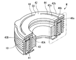
- FIG. 1 It is a longitudinal section showing an example of composition of a scroll type compressor provided with an electromagnetic clutch in this embodiment. It is a perspective sectional view of an electromagnetic clutch.
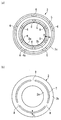
- (A) is a top view of an armature
- (b) is a top view of a rotor. It is an expanded sectional view which shows the contact part of an armature and a rotor.
- (A) is a top view of the conventional rotor
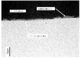
- (b) is a top view of the conventional armature. It is a cross-sectional photograph of the groove part of an armature.
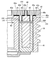
- FIG. 1 is a longitudinal sectional view showing a configuration example of a scroll compressor provided with an electromagnetic clutch.
- the scroll compressor (compressor) 10 includes a front housing 11 and a rear housing 12, and includes a housing 13 in which the front housing 11 and the rear housing 12 are integrally fastened and fixed by bolts (not shown). ing.
- crankshaft (rotary shaft) 14 is rotatably supported around a rotation axis L via a main bearing (needle bearing) 15 and a sub-bearing (needle bearing) 16.
- One end side (the left side in FIG. 1) of the crankshaft 14 is a small diameter shaft portion 14a, and the small diameter shaft portion 14a penetrates the front housing 11 and protrudes to one end side.
- An electromagnetic clutch M is mounted on the protruding portion of the small-diameter shaft portion 14a, and between the pulley 18 provided rotatably on the outer peripheral surface of the small-diameter boss portion 11a on one end side of the front housing 11 via a bearing 17.
- the power is intermittent.
- Power is transmitted to the pulley 18 from an external drive source such as an engine (not shown) via a V-belt or the like.
- an external drive source such as an engine (not shown) via a V-belt or the like.
- a mechanical seal (lip seal) 19 is provided between the main bearing 15 and the sub-bearing 16, thereby hermetically sealing the inside of the housing 13 and the atmosphere.
- a large-diameter shaft portion 14 b is provided on the other end side (right side in FIG. 1) of the crankshaft 14, and the large-diameter shaft portion 14 b has a predetermined dimension from the rotation axis L of the crankshaft 14.
- An eccentric pin 14c is integrally provided in an eccentric state.
- the large-diameter shaft portion 14b and the small-diameter shaft portion 14a of the crankshaft 14 are rotatably supported by the front housing 11 via the main bearing 15 and the sub bearing 16, respectively.
- the orbiting scroll member 22 is connected to the eccentric pin 14c via the balance bush 20 and the drive bearing 21, and the orbiting scroll member 22 is driven to rotate by rotating the crankshaft 14. It has become.
- the balance bush 20 is formed with a balance weight 20a for removing an unbalanced load generated when the orbiting scroll member 22 is orbitally driven.
- the balance weight 20a is orbited when the orbiting scroll member 22 is orbitally driven.
- a pair of fixed scroll portions 24 and a turning scroll member 22 constituting a scroll type compression mechanism 23 are incorporated.
- the fixed scroll member 24 includes a fixed end plate 24a and a spiral wrap 24b erected from the fixed end plate 24a.
- the orbiting scroll member 22 includes the orbiting end plate 22a and the orbiting end plate. And a spiral wrap 22b erected from 22a.
- the fixed scroll member 24 and the orbiting scroll member 22 are assembled in such a state that the centers of the fixed scroll member 24 and the orbiting scroll member 22 are separated by the orbiting radius, and the spiral wraps 24b and 22b are engaged with each other with a phase difference of 180 degrees.
- a pair of compression chambers C defined by the end plates 24a and 22a and the spiral wraps 24b and 22b are formed symmetrically between the scroll members 24 and 22 with respect to the center of the scroll. Will be.
- the fixed scroll member 24 is fixed to the inner surface (bottom surface) of the rear housing 12 via a bolt 25.
- an eccentric pin 14 c provided on one end side of the crankshaft 14 is fitted into a boss portion 26 provided on the back surface of the orbiting end plate 22 a via a balance bush 20 and a drive bearing 21.
- the crankshaft 14 is connected.
- the orbiting scroll member 22 has a thrust receiving surface 11b formed on the front housing 11 supported on the back surface of the orbiting end plate 22a, and the orbiting scroll member 22 is interposed between the thrust receiving surface 11b and the orbiting scroll member 22 on the back surface.
- the orbiting scroll member 22 is configured to be revolved and driven with respect to the fixed scroll member 24 while being prevented from rotating by the rotation-preventing pinning mechanism 27 mounted.
- This rotation-preventing pin ring mechanism 27 includes a pin 27a and a ring 27b, and a pin hole 11c for standing the pin 27a on one of the back surface of the fixed end plate 22a of the orbiting scroll member 22 and the thrust receiving surface 11b is provided on the other side. Is provided with a ring hole 22c for fitting the ring 27b.
- the thrust receiving surface 11 b is provided with a pin hole 11 c for standing the pin 27 a
- the orbiting scroll member 22 is provided with a ring hole 22 c for fitting the ring 27 b.
- the pin holes 11c and the ring holes 22c are provided at a plurality of locations in the circumferential direction, generally 3 to 4 locations (4 locations in the present embodiment).
- a discharge port 24c for discharging compressed refrigerant gas is opened at the center of the fixed end plate 24a of the fixed scroll member 24.
- the discharge port 24c is connected to the fixed end plate 24a via a retainer 28.
- a discharge reed valve (not shown) is provided.
- a seal member (not shown) such as an O-ring is installed on the back surface of the fixed end plate 24 a of the fixed scroll member 24 so as to be in close contact with the inner surface of the rear housing 12.
- a discharge chamber 29 partitioned from the internal space (sealed space) is formed. Thereby, the internal space of the housing 13 excluding the discharge chamber 29 functions as the suction chamber 30.
- Refrigerant gas returning from the refrigeration cycle is sucked into the suction chamber 30 via a suction port (not shown) provided in the front housing 11, and the fixed scroll member 24 and the orbiting scroll member are passed through the suction chamber 30.
- the refrigerant gas is sucked into the compression chamber C formed between the two.
- a sealing member 31 such as an O-ring is installed on the joint surface between the front housing 11 and the rear housing 12, and the suction chamber 30 in the housing 13 is hermetically sealed from the atmosphere.
- the scroll compressor 10 configured as described above operates as follows.
- the rotational driving force transmitted from the external drive source to the pulley 18 is transmitted to the crankshaft 14 via the electromagnetic clutch M, and the crankshaft 14 is rotated.
- the orbiting scroll member 22 connected to the eccentric pin 14c of the crankshaft 14 via the balance bush 20 and the drive bearing 21 is prevented from rotating by the rotation preventing pin ring mechanism 27 while being rotated against the fixed scroll member 24. Revolved and driven.
- the revolving orbiting drive of the orbiting scroll member 22 causes the refrigerant gas in the suction chamber 30 to be sucked into the compression chamber C formed at the radially outermost side.
- the compression chamber C is closed by suction at a predetermined swivel angle position, the compression chamber C is moved to the center side while the volume is reduced in the circumferential direction and the lap height direction.
- the refrigerant gas is compressed, and when the compression chamber C reaches a position where it communicates with the discharge port 24c, the discharge reed valve is pushed open and the compressed gas is discharged into the discharge chamber 29. It is discharged out of the compressor through a discharge port (not shown) provided in the rear housing 12.
- the scroll compressor 10 described above includes an electromagnetic clutch M that is mounted on the crankshaft 14 of the compression mechanism and transmits power.
- the electromagnetic clutch M attracts the magnetic armature 42 to the contact surface of the rotor 43 by the magnetic force of the electromagnetic coil 41, and transmits the power by integrally coupling the armature 42 and the rotor 43.
- the radial direction of the armature 42 is divided into two by a groove (intermediate groove) 44 having a width b, and an inner ring 42a, An outer peripheral ring 42b is formed.
- the groove 44 is divided at a plurality of locations in the circumferential direction by a bridge 50 that connects the inner ring 42a and the outer ring 42b.
- the grooves 44 divided by the bridge 50 each form an arc having the same width with the groove width being b.
- channels 45A and 45B demonstrated below are formed by laser processing.
- the electromagnetic clutch M of the present embodiment includes two grooves (inner circumferential grooves) 45A and grooves (outer circumferences) in which the radial direction of the rotor 43 has a width a.
- Groove) 45B and is divided into three to form an inner ring 43a, a center ring 43b, and an outer ring 43c.
- the two grooves 45A and 45B are divided at a plurality of locations in the circumferential direction by bridges 51A and 51B connecting the inner ring 43a, the center ring 43b, and the outer ring 43c.
- the grooves 45A and 45B divided by the bridges 51A and 51B each form an arc having the same width with the groove width being a.
- the width of the grooves 44, 45A and 45B is preferably 0.8 to 1.2 mm. This is because the contact area between the rotor and the armature can be increased without increasing the size of the electromagnetic clutch itself, and the occurrence of a short circuit in the magnetic flux on both sides of the grooves 44, 45A and 45B can be suppressed.
- the grooves 44, 45 ⁇ / b> A and 45 ⁇ / b> B formed in this way allow the rotor contact surface 46 a of the armature 42 and the armature contact surface 46 b of the rotor 43 to be connected to the inner peripheral ring 43 a of the rotor 43.
- An annular first contact surface A1 facing the inner ring 42a, an annular second contact surface A2 where the inner ring 42a of the armature 42 faces the center ring 43b of the rotor 43, and an outer ring 42b of the armature 42 are the rotor.
- the annular third contact surface A3 facing the central ring 43b of 43 and the annular fourth contact surface A4 of the outer ring 43c of the rotor 43 facing the outer ring 42b of the armature 42 generate a suction force.
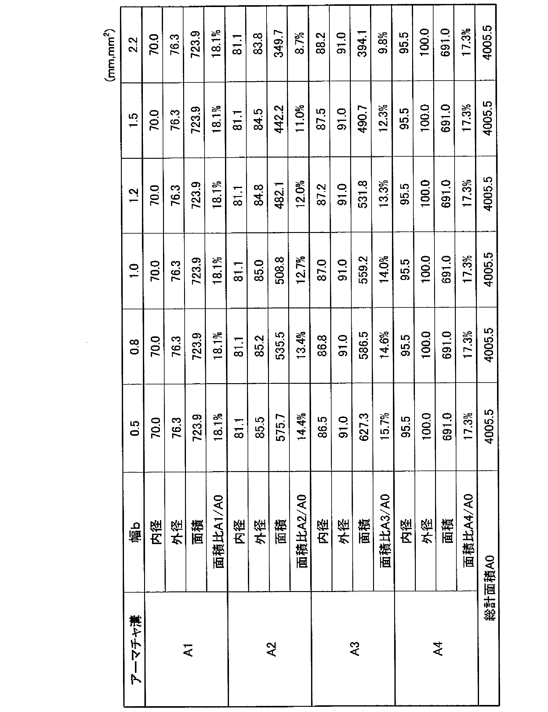
- the first contact surface A1, the second contact surface A2, the third contact surface A3, and the fourth contact surface A4 are configured so that the areas of the annular areas are substantially equal to each other so that the suction force is equalized. It is preferable to form the grooves 44, 45A, 45B. Further, in order to increase the force against the rotational torque when the armature 42 and the rotor 43 are attracted to each other, of the first contact surface A1, the second contact surface A2, the third contact surface A3, and the fourth contact surface A4, The area of the fourth contact surface A4 on the outer periphery may be maximized.
- a metal oxide layer 100 is formed on the surface of the wall surface that partitions each of the grooves 44, 45A, 45B.
- the metal oxide layer 100 formed on the wall surface defining the groove 44 is formed from the upper end edge to the lower end edge of the groove 44.
- the portion formed at the lower edge of the metal oxide layer 100 is in contact with the second contact surface A2 and the third contact surface A3.
- the metal oxide layer 100 formed on the wall surface defining the groove 45A is formed from the upper end edge to the lower end edge of the groove 45A.
- the portion formed at the upper edge of the metal oxide layer 100 is in contact with the first contact surface A1 and the second contact surface A2.
- the metal oxide layer 100 formed on the wall surface defining the groove 45B is formed from the upper end edge to the lower end edge of the groove 45B.
- the portion formed at the upper edge of the metal oxide layer 100 is in contact with the third contact surface A3 and the fourth contact surface A4.
- the metal oxide layer 100 may be provided with a thickness of 0.1 ⁇ m to 10 ⁇ m. However, as will be described later, the metal oxide layer 100 is preferably 0.5 to 3 ⁇ m thick.
- FIG. 7 shows a cross-sectional photograph of the vicinity of the groove 44 of the armature 42. In order to form the metal oxide layer 100 shown in FIG.
- a 4.5 mm thick mild steel material (SPHC: hot rolled steel plate) was used to form grooves at a speed of 3.5 m / min using a CO 2 laser with an output of 2500 W. 44 was processed and formed.
- a metal oxide layer 100 having a thickness of about 0.5 ⁇ m to 3 ⁇ m is attached to the surface of the wall surface defining the groove 44 of the armature 42. This is because the metal oxide particles generated by being crushed from the metal oxide layer 100 by the sliding contact between the armature 42 and the rotor 43 are likely to be about 0.1 ⁇ m to 1 ⁇ m.
- the metal oxide layer 100 is not attached to the surface of the groove 44.
- the metal oxide layer is provided with a thickness of about 1 ⁇ m.
- the object of the present invention can be achieved if a part of the metal oxide layer is deposited with a thickness of 0.1 ⁇ m to 10 ⁇ m.
- FIG. 8 shows the result of measuring the surface of the metal oxide layer 100 shown in FIG. 7 by micro Vickers.
- the load was 3 gf
- the Vickers hardness was about 1000 (in the present specification, it is shown as 1000 HV0.003, and the others are the same), and the values were about 650HV0.005 and 500HV0.010. This is because when the load becomes heavy, the mild steel material on the surface of the armature also affects the measured value.
- the Vickers hardness of the armature 42 may be 100 HV10 to 350 HV10, and the laser light may be irradiated so that the Vickers hardness of the metal oxide layer 100 is 700 HV0.003 to 1200 HV0.003.
- the most preferable Vickers hardness of the metal oxide layer 100 is about 1000 ⁇ 100HV0.003.
- the metal oxide layer 100 is not called hydrous iron oxide Fe 2 O 3 H 2 O but a triiron tetroxide (Fe 3 O 4 ) generated by high-temperature oxidation and is commonly called “black skin”. Is.
- the rotor contact surface 46a and the armature contact surface 46b are in sliding contact with each other at the first contact surface A1, the second contact surface A2, the third contact surface A3, and the fourth contact surface A4. Wear.
- the metal oxide layer 100 facing the lower end edge of the groove 44 formed on the wall surface defining the groove 44 is in sliding contact with the second contact surface A2 and the third contact surface A3, and is crushed into fine particles. .
- the groove 45A is slid with the first contact surface A1 and the second contact surface A2, and the groove 45B is slid with the third contact surface A3 and the fourth contact surface A4. By the contact, particles are generated from the metal oxide layer 100.
- the fine particles generated from the metal oxide layer 100 have a particle size of, for example, about 0.1 to 1 ⁇ m, and the first contact surface A1, the second contact surface A2, the third contact surface A3, and the fourth contact. Enter surface A4. Since the metal oxide layer 100 is formed from the upper end edge to the lower end edge of the grooves 44, 45A, 45B, as long as the electromagnetic clutch M is used, the particles can be continuously supplied to the contact surface.
- the first contact surface A1, the second contact surface A2, the third contact surface A3, and the fourth contact surface A4 enter the first contact surface A1, the second contact surface A2, and the fourth contact surface A4.
- Particles (hereinafter referred to as metal oxide particles) generated from the metal oxide layer 100 that have entered the respective contact surfaces A1 to A4 function as resistance at the contact surfaces, and the frictional force between the rotor 43 and the armature 42. And the slip between the rotor 43 and the armature 42 can be suppressed.
- the metal oxide particles are successively supplied as the rotor 43 and the armature 42 are worn, the metal oxide particles can be constantly supplied between the rotor 43 and the armature 42.
- the metal oxide layer 100 can achieve the above-described effects even if it is formed in any one of the grooves 44, 45A, and 45B.
- the grooves 44, 45A, 45B are formed by laser processing.
- laser processing the plate material is cut (fused) into a predetermined shape by moving the laser beam, the armature 42, and the rotor 43 relative to each other while irradiating the plate material forming the armature 42 and the rotor 43 with laser light.
- the grooves 44, 45A and 45B are formed.
- the metal oxide layer 100 can be formed only by laser light irradiation, more preferably, oxygen is blown to the laser irradiation light position. Thereby, the metal oxide layer 100 can be formed efficiently. Blowing oxygen also increases the cutting speed.
- the second contact surface A2 and the third contact located on both sides of the groove 44 of the armature 42.
- the area of one or both of the surfaces A3 tends to be the smallest. Therefore, the area of the second contact surface A2 and the third contact surface A3 is 11% or more with respect to the total area A0 between the inner diameter side of the first contact surface A1 and the outer diameter side of the fourth contact surface A4. It is preferable to form so as to occupy.
- the area of the second contact surface A2 is 11% to 14% with respect to the total area A0, and the area of the third contact surface A3 is 12% to 15% with respect to the total area A0.
- the area of the second contact surface A2 or the third contact surface A3 having the smallest area among the contact surface A1, the second contact surface A2, the third contact surface A3, and the fourth contact surface A4 is more than a certain value.
- the groove 44 positioned between the second contact surface A2 and the third contact surface A3 having the smallest area has a width b of 0.
- the thickness is preferably 5 to 1.5 mm, and more preferably 0.8 to 1.2 mm.
- the width b of the groove 44 is set smaller than the width a of the grooves 45A and 45B.
- the width b of the groove 44 can be made equal to the width a of the grooves 45A and 45B.
- the width b of the groove 44 can be set smaller than the sum of the width a of the groove 45A and the width a of the groove 45B.
- the widths a, b of the grooves 44, 45A, 45B are set as low as possible within a range that does not cause a short circuit of magnetic flux at low cost. be able to.
- the pressure-bonding area between the armature 42 and the rotor 43 can be increased without increasing the size of the armature 42 and the rotor 43, and the mutual suction force can be increased.
- the torque transmission capability of the electromagnetic clutch M can be increased, and the scroll compressor 10 can be increased in torque.
- the inner peripheral surfaces of the grooves 44, 45A, 45B are hardened by heat input by the laser beam, and the hardness of the base material of the armature 42 and the rotor 43 is increased. It is larger than the hardness. As a result, it is possible to increase the strength of the wall surfaces that define the grooves 44, 45A, 45B.
- the above-described armature 42 and rotor 43 may be made of, for example, mild steel such as SPHC (hot rolled steel plate), SPCC (cold rolled steel plate), or low carbon steel such as S12C. This is because the steel material increases in hardness when the carbon content is increased, but on the other hand, the ferrite phase decreases and the magnetic flux density (magnetic permeability) of the electromagnetic clutch decreases.
- mild steel such as SPHC (hot rolled steel plate), SPCC (cold rolled steel plate), or low carbon steel such as S12C.
- the armature 42 and the rotor 43 are made of a steel material such as carbon steel, and have an annular shape with an outer diameter of 110 mm and an inner diameter of 65 mm.
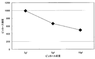
- the width b of the groove 44 of the armature 42 is changed to 0.5, 0.8, 1.0, 1.2, 1.5, 2.2 (current) mm.
- the ratio of the attractive force between the armature 42 and the rotor 43 when a magnetic field was generated by the electromagnetic coil 41 under the same conditions was obtained by simulation using an electronic computer.
- the configuration of the scroll compressor 10 has been described.
- the configuration of other parts other than the configuration related to the main part of the present invention is not limited at all.
- the configuration described in the above embodiment can be selected or changed to another configuration as appropriate.
- the rotor 43 has a center position C0 on a center line obtained by dividing the groove width a of the groove 45A into two in the radial direction, and a groove tip radius (hereinafter abbreviated as “radius”) R.
- the circular arc drawn as may be a curved shape at the end of the groove. That is, the circular end 45A1 is formed by an arc obtained by excluding an arc portion where the groove width a of the groove 45A abuts from an arc of a circle having a radius R.
- the circular end 45A1 is set so that the diameter 2R is larger than the groove width a (2R> a). Therefore, the circular end 45A1 bulges evenly toward the inner and outer peripheral sides of the groove 45A. It has a curved part to do.
- the rotor 43 of such an electromagnetic clutch M is formed as a circular end 45A1 having a curved shape, the end of the groove 45A divided by the bridge 51A bulges outside the groove width a. While ensuring the strength of the bridge portion provided with the bridge 51 ⁇ / b> A, the bridge width W ⁇ b> 1 can be made narrower than before. That is, in the electromagnetic clutch M that receives power transmitted from an external drive source such as an engine to the pulley 18 via a V-belt or the like, the circular end 45A1 disperses the stress of the bridge 51A against the external force acting from the outer peripheral side of the rotor 43. Therefore, even if the bridge width W1 is narrowed, the strength is prevented from decreasing and the lack of strength can be solved.
- the electromagnetic clutch M that employs the circular end 45A1 to narrow the bridge width W1 can increase the attractive force of the armature 42 while maintaining the strength of the bridge portion, thereby increasing the torque transmission capability.
- slipping troubles occurring between the armature 42 and the rotor 43 can be prevented or suppressed.
- the circular center position C1 may be a circular end 45A2 moved to the outer peripheral side, or, for example, as shown in FIG. 12, the circular center position C2 may be moved to the inner peripheral side.
- the circular end 45A3 may be used.
- the curved shape formed at the end of the groove 45A is not limited to the circular end 45A1, 45A2, 45A3 of the arc described above, for example, an ellipse provided with a bulging portion wider than the groove width a. Shapes can also be used.
- the circular end portions 45A1, 45A2, and 45A3 described above are applied only to the inner circumferential groove 45A, they may be employed in the outer circumferential groove 45B as necessary.
- SYMBOLS 10 Scroll type compressor (compressor), 41 ... Electromagnetic coil, 42 ... Armature, 42a ... Inner ring, 42b ... Outer ring, 43 ... Rotor, 43a ... Inner ring, 43b ... Central ring, 43c ... Outer ring 44 ... groove (intermediate groove), 45A ... groove (inner circumferential groove), 45B ... groove (outer circumferential groove), 46a ... rotor contact surface, 46b ... armature contact surface, 100 ... metal oxide layer, A1 ... first contact Surface, A2 ... second contact surface, A3 ... third contact surface, A4 ... fourth contact surface, M ... electromagnetic clutch
Landscapes
- Engineering & Computer Science (AREA)
- General Engineering & Computer Science (AREA)
- Mechanical Engineering (AREA)
- Physics & Mathematics (AREA)
- Electromagnetism (AREA)
- Compressors, Vaccum Pumps And Other Relevant Systems (AREA)
- Rotary Pumps (AREA)
Abstract
アーマチャ42とロータ43の溝44、45A、45Bをレーザ加工により形成する際に、溝44、45A、45Bを区画する壁面に金属酸化物層100を形成する。この金属酸化物層100は、電磁クラッチを使用する過程で、第一接触面A1~第四接触面A4と摺接することにより、一部が砕け又は剥離して、金属酸化物からなる粒子が生成される。この粒子はアーマチャ42とロータ43との接触面に進入して、両者間の摩擦力を増大させてすべりを防止する。その結果、電磁クラッチMにおけるトルク伝達能力を増大させ、スクロール型圧縮機の高トルク化を図る。
Description
本発明は、たとえば車両用空調装置等に適用されて動力の伝達を行う電磁クラッチ及びこの電磁クラッチを備えた圧縮機、電磁クラッチの製造方法に関するものである。
従来、車両用空調装置に用いられる圧縮機は、駆動源との間に配設して動力の伝達を行う電磁クラッチを備えている。
電磁クラッチは、電磁力により動力の伝達、もしくは非伝達を選択して行なうことができ、たとえば図5に示すように、電磁コイル1の磁力によりアーマチャ2をロータ3へ吸引することで、アーマチャ2とロータ3とを一体に結合させて動力の伝達を行うように構成されている(例えば、特許文献1参照。)。図示の構成例では、アーマチャ2の半径方向幅が2分割され、かつ、ロータ3の半径方向幅が3分割されることにより、アーマチャ2とロータ3との接触面(ギャップ)4は、半径方向に4分割されたものとなる。なお、以下の説明では、接触面4のロータ3側についてはアーマチャ接触面4aと呼び、接触面4のアーマチャ2側についてはロータ接触面4bと呼ぶことにする。
電磁クラッチは、電磁力により動力の伝達、もしくは非伝達を選択して行なうことができ、たとえば図5に示すように、電磁コイル1の磁力によりアーマチャ2をロータ3へ吸引することで、アーマチャ2とロータ3とを一体に結合させて動力の伝達を行うように構成されている(例えば、特許文献1参照。)。図示の構成例では、アーマチャ2の半径方向幅が2分割され、かつ、ロータ3の半径方向幅が3分割されることにより、アーマチャ2とロータ3との接触面(ギャップ)4は、半径方向に4分割されたものとなる。なお、以下の説明では、接触面4のロータ3側についてはアーマチャ接触面4aと呼び、接触面4のアーマチャ2側についてはロータ接触面4bと呼ぶことにする。
また、ロータ3のアーマチャ接触面4aは、たとえば図6(a)に示すように、溝幅をaとした2本の溝5によって半径方向が3分割され、内周リング3a、中央リング3b及び外周リング3cが形成されている。そして、2本の溝5は、内周リング3a、中央リング3b及び外周リング3cを繋ぐブリッジ6により、円周方向が複数箇所で分断されている。
また、アーマチャ2の半径方向についても、たとえば図6(b)に示すように、溝幅をbとした溝7により内周部2a及び外周部2bに2分割されている。そして、アーマチャ2側の溝7についても、内周部2a及び外周部2bを繋ぐブリッジ8により、円周方向が複数個所で分断されている。この場合のアーマチャ2は、板状素材からパンチングにより打ち抜き加工した板で構成される。
また、アーマチャ2の半径方向についても、たとえば図6(b)に示すように、溝幅をbとした溝7により内周部2a及び外周部2bに2分割されている。そして、アーマチャ2側の溝7についても、内周部2a及び外周部2bを繋ぐブリッジ8により、円周方向が複数個所で分断されている。この場合のアーマチャ2は、板状素材からパンチングにより打ち抜き加工した板で構成される。
上述した従来の電磁クラッチは、ブリッジ6、8に流れる短絡磁束等によりアーマチャ2とロータ3との間に十分な吸引力を確保できない場合には、トルク伝達能力が減少する。すなわち、吸引力不足に起因してトルク伝達能力が減少するような場合には、アーマチャ2とロータ3との間に滑りのトラブルが発生するという問題を有している。
そこで、アーマチャ2とロータ3の接触面積を増大させて摩擦力を大きくすることが考えられる。これには、アーマチャ2及びロータ3の外径を増やすことも考えられるが、電磁クラッチの外径寸法が増大して大型化するため好ましくない。
本発明は、このような技術的課題に基づいてなされたもので、電池クラッチの外形寸法を増大させることなくアーマチャとロータとの間の摩擦力を増加させることのできる電磁クラッチ、このクラッチを用いた圧縮機、この電磁クラッチの製造方法を提供することを目的とする。
かかる目的のもとになされた本発明は、電磁コイルの磁力によりアーマチャをロータの接触面に吸引し、アーマチャとロータとを一体結合させて動力を伝達する電磁クラッチにおいて、ロータのアーマチャ接触面が、ロータ側溝によって、径方向に分割されるとともに、アーマチャのロータ接触面が、アーマチャ側溝によって分割され、ロータ側溝を区画する壁面及びアーマチャ側溝を区画する壁面の少なくとも一方の表面に金属酸化物層が形成されていることを特徴とする。なお、以下では、ロータ側溝を区画する壁面に形成される金属酸化物層をロータ側酸化物層と略し、アーマチャ側溝を区画する壁面に形成される金属酸化物層をアーマチャ側酸化物層と略すことがある。
このように構成された電磁クラッチを使用することにより、ロータのアーマチャ接触面とアーマチャのロータ接触面とが摺接、摩耗するが、これにともなって、ロータのアーマチャ接触面にはアーマチャ側酸化物層が摺接し、また、アーマチャのロータ接触面にはロータ側酸化物層が摺接する。そのためにこれら金属酸化物層の一部が砕け又は剥離(以下、砕けると総称する)して金属酸化物粒子が生成され、この粒子はロータのアーマチャ接触面やアーマチャのロータ接触面に供給される。これにより、外形寸法を増大させることなくアーマチャとロータとの間の摩擦力を増大させて滑りを抑制することが出来る。
また、金属酸化物層は0.1μmから10μmの厚さであることが好ましい。さらに、ロータ及びアーマチャのビッカース硬度が100HV10から350HV10であり、金属酸化物層のビッカース硬度が700HV0.003から1200HV0.003であることが好ましい。このように、金属酸化物層のビッカース硬度が高いので、金属酸化物層から生成された粒子が、吸引力で接触しているアーマチャとロータの間に進入して、アーマチャとロータとの間の摩擦力を増大させ滑りを抑制することが出来る。
さらに、アーマチャのロータ接触面に形成された溝の幅が0.8~1.2mmとされていることが好ましい。これにより、電磁クラッチを大型化することなく、ロータとアーマチャとの接触面積を増大でき吸引力を増加させる。その結果、アーマチャとロータとの間の摩擦力を増加させ滑りを抑制することが出来る。
また、本発明にかかる圧縮機は、圧縮機構の軸部に装着されて動力を伝達するように上述の電磁クラッチを備えることが出来る。
さらに、本発明にかかる電磁クラッチの製造方法は、電磁コイルの磁力によりアーマチャをロータの接触面に吸引し、アーマチャとロータとを一体結合させて動力を伝達し、ロータのアーマチャ接触面が、ロータ側溝によって、径方向に分割されるとともに、アーマチャのロータ接触面が、アーマチャ側溝によって、分割された電磁クラッチの製造方法において、レーザ加工により、ロータ側溝を区画する壁面及びアーマチャ側溝を区画する壁面の少なくとも一方の表面に金属酸化物層を形成することを特徴とする。この電磁クラッチの製造方法において、金属酸化物を形成するレーザ加工により、ロータ側溝及びアーマチャ側溝の少なくとも一方を形成する際に、金属酸化物層を形成することが好ましい。また、レーザ加工中は、レーザ光の照射位置、つまりロータ側溝又はアーマチャ側溝に酸素を吹きつけることが好ましい。
このような電磁クラッチの製造方法によれば、レーザ光を用いているので、アーマチャやロータに微細な溝(ロータ側溝、アーマチャ側溝)を形成できるととともに、レーザ光照射により発生する熱により溝の形成と同時に金属酸化物層を容易に形成することが出来る。また、酸素ガスをレーザ照射位置に吹き付けると、酸化反応熱により切断部の溶解が促進されるので、溝の加工速度を上げる事が出来る。
本発明によれば、電磁クラッチを使用することにより、ロータのアーマチャ接触面に摺接したアーマチャ側酸化物層やアーマチャのロータ接触面に摺接したロータ側酸化物層が粒子となり、ロータのアーマチャ接触面やアーマチャのロータ接触面に供給される。これにより、アーマチャとロータとの間の摩擦力を増大させ滑りを抑制することが出来る。
以下、本発明による電磁クラッチ及びこれを備えた圧縮機について、その一実施形態を図面に基づいて説明する。
図1は、電磁クラッチを備えたスクロール型圧縮機の構成例を示す縦断面図である。このスクロール型圧縮機(圧縮機)10は、フロントハウジング11とリアハウジング12とを備え、これらフロントハウジング11とリアハウジング12とをボルト(図示せず)により一体的に締め付け固定したハウジング13を備えている。
図1は、電磁クラッチを備えたスクロール型圧縮機の構成例を示す縦断面図である。このスクロール型圧縮機(圧縮機)10は、フロントハウジング11とリアハウジング12とを備え、これらフロントハウジング11とリアハウジング12とをボルト(図示せず)により一体的に締め付け固定したハウジング13を備えている。
フロントハウジング11の内部には、メイン軸受(ニードル軸受)15及びサブ軸受(ニードル軸受)16を介してクランク軸(回転軸)14がその回転軸線L回りに回転自在に支持されている。クランク軸14の一端側(図1において左側)は小径軸部14aとされ、この小径軸部14aは、フロントハウジング11を貫通して一端側に突出している。小径軸部14aの突出部には、電磁クラッチMが装着され、フロントハウジング11の一端側の小径ボス部11aの外周面に軸受17を介して回転自在に設けられているプーリー18との間で動力が断続されるようになっている。プーリー18には、図示していないエンジン等の外部駆動源からVベルト等を介して動力が伝達されることとなる。
なお、メイン軸受15とサブ軸受16との間には、メカニカルシール(リップシール)19が設けられており、これによってハウジング13内と大気との間を気密にシールしている。
なお、メイン軸受15とサブ軸受16との間には、メカニカルシール(リップシール)19が設けられており、これによってハウジング13内と大気との間を気密にシールしている。
一方、クランク軸14の他端側(図1において右側)には、大径軸部14bが設けられており、この大径軸部14bには、クランク軸14の回転軸線Lよりも所定寸法だけ偏心した状態で偏心ピン14cが一体に設けられている。そして、これらクランク軸14の大径軸部14b及び小径軸部14aが、それぞれメイン軸受15及びサブ軸受16を介してフロントハウジング11に回転自在に支持されることとなる。
また、偏心ピン14cには、バランスブッシュ20及びドライブ軸受21を介して、旋回スクロール部材22が連結されており、クランク軸14が回転されることにより、旋回スクロール部材22が旋回駆動されるようになっている。
また、偏心ピン14cには、バランスブッシュ20及びドライブ軸受21を介して、旋回スクロール部材22が連結されており、クランク軸14が回転されることにより、旋回スクロール部材22が旋回駆動されるようになっている。
バランスブッシュ20には、旋回スクロール部材22が旋回駆動されることにより生じるアンバランス荷重を除去するためのバランスウェイト20aが形成されており、旋回スクロール部材22の旋回駆動とともに旋回されるようになっている。
ハウジング13の内部には、スクロール型圧縮機構23を構成する一対の固定スクロール部24と旋回スクロール部材22が組み込まれている。
固定スクロール部材24は、固定端板24aと、この固定端板24aから立設された渦巻き状ラップ24bとを備えており、一方、旋回スクロール部材22は、旋回端板22aと、この旋回端板22aから立設された渦巻き状ラップ22bとを備えている。
ハウジング13の内部には、スクロール型圧縮機構23を構成する一対の固定スクロール部24と旋回スクロール部材22が組み込まれている。
固定スクロール部材24は、固定端板24aと、この固定端板24aから立設された渦巻き状ラップ24bとを備えており、一方、旋回スクロール部材22は、旋回端板22aと、この旋回端板22aから立設された渦巻き状ラップ22bとを備えている。
固定スクロール部材24及び旋回スクロール部材22は、各々の中心を旋回半径分だけ離すとともに、渦巻き状ラップ24b、22bどうしが180度位相をずらせて噛み合わせた状態で組み込まれる。これによって、両スクロール部材24、22間には、端板24a、22aと渦巻き状ラップ24b、22bとにより区画された(仕切られた)一対の圧縮室Cがスクロールの中心に対して対称に形成されることとなる。
固定スクロール部材24は、ボルト25を介してリアハウジング12の内面(底面)に固定されている。旋回スクロール部材22は、旋回端板22aの背面に設けられているボス部26に、クランク軸14の一端側に設けられている偏心ピン14cが、バランスブッシュ20及びドライブ軸受21を介して嵌め込まれることによりクランク軸14に連結されている。
また、旋回スクロール部材22は、フロントハウジング11に形成されているスラスト受け面11bに旋回端板22aの背面が支持されており、このスラスト受け面11bと旋回スクロール部材22の背面との間に介装される自転阻止用ピンリング機構27により、旋回スクロール部材22は、自転を阻止されながら固定スクロール部材24に対して公転旋回駆動されるように構成されている。
また、旋回スクロール部材22は、フロントハウジング11に形成されているスラスト受け面11bに旋回端板22aの背面が支持されており、このスラスト受け面11bと旋回スクロール部材22の背面との間に介装される自転阻止用ピンリング機構27により、旋回スクロール部材22は、自転を阻止されながら固定スクロール部材24に対して公転旋回駆動されるように構成されている。
この自転阻止用ピンリング機構27は、ピン27aとリング27bとを備えており、旋回スクロール部材22の固定端板22aの背面またはスラスト受け面11bの一方にピン27aを立てるピン穴11cが、他方にリング27bを嵌合するリング穴22cが設けられている。本実施形態では、スラスト受け面11bにピン27aを立てるピン穴11cが設けられ、旋回スクロール部材22にリング27bを嵌めるリング穴22cが設けられている。
なお、これらピン穴11c及びリング穴22cは、周方向に複数箇所、一般的には3ないし4箇所(本実施形態では4箇所)設けられている。
なお、これらピン穴11c及びリング穴22cは、周方向に複数箇所、一般的には3ないし4箇所(本実施形態では4箇所)設けられている。
さらに、固定スクロール部材24の固定端板24aの中央部には、圧縮された冷媒ガスを吐出する吐出ポート24cが開口されており、この吐出ポート24cには、固定端板24aにリテーナ28を介して取り付けられる吐出リード弁(図示せず)が設けられている。
また、固定スクロール部材24の固定端板24aの背面には、リアハウジング12の内面に密接されるようOリング等のシール部材(図示せず)が設置され、リアハウジング12との間でハウジング13の内部空間(密閉空間)から区画された吐出チャンバー29が形成されている。これにより、吐出チャンバー29を除くハウジング13の内部空間が、吸入チャンバー30として機能するようになっている。
また、固定スクロール部材24の固定端板24aの背面には、リアハウジング12の内面に密接されるようOリング等のシール部材(図示せず)が設置され、リアハウジング12との間でハウジング13の内部空間(密閉空間)から区画された吐出チャンバー29が形成されている。これにより、吐出チャンバー29を除くハウジング13の内部空間が、吸入チャンバー30として機能するようになっている。
吸入チャンバー30には、フロントハウジング11に設けられている吸入口(図示せず)を介して冷凍サイクルから戻ってくる冷媒ガスが吸入され、この吸入チャンバー30を経て固定スクロール部材24と旋回スクロール部材22との間に形成される圧縮室Cに冷媒ガスが吸い込まれるようになる。
なお、フロントハウジング11とリアハウジング12との間の接合面には、Oリング等のシール部材31が設置され、ハウジング13内の吸入チャンバー30を大気から気密にシールしている。
なお、フロントハウジング11とリアハウジング12との間の接合面には、Oリング等のシール部材31が設置され、ハウジング13内の吸入チャンバー30を大気から気密にシールしている。
以上のように構成されたスクロール型圧縮機10は、以下のように動作する。
外部駆動源からプーリー18に伝達された回転駆動力を、電磁クラッチMを介してクランク軸14に伝達し、クランク軸14を回転させる。すると、クランク軸14の偏心ピン14cにバランスブッシュ20及びドライブ軸受21を介して連結されている旋回スクロール部材22が、自転阻止用ピンリング機構27により自転を阻止されながら、固定スクロール部材24に対して公転旋回駆動される。
外部駆動源からプーリー18に伝達された回転駆動力を、電磁クラッチMを介してクランク軸14に伝達し、クランク軸14を回転させる。すると、クランク軸14の偏心ピン14cにバランスブッシュ20及びドライブ軸受21を介して連結されている旋回スクロール部材22が、自転阻止用ピンリング機構27により自転を阻止されながら、固定スクロール部材24に対して公転旋回駆動される。
そして、この旋回スクロール部材22の公転旋回駆動により、半径方向最外方に形成される圧縮室C内に、吸入チャンバー30内の冷媒ガスが吸い込まれる。圧縮室Cは、所定の旋回角位置で吸入締め切りされた後、その容積が周方向及びラップ高さ方向に減少されながら中心側へと移動される。この間に冷媒ガスは圧縮され、圧縮室Cが吐出ポート24cに連通する位置に達すると、吐出リード弁が押し開かれて圧縮されたガスは吐出チャンバー29内に吐出され、この圧縮冷媒ガスは、リアハウジング12に設けられている吐出口(図示せず)を経て圧縮機外へと吐出される。
さて、上述したスクロール型圧縮機10は、圧縮機構のクランク軸14に装着されて動力を伝達する電磁クラッチMを備えている。この電磁クラッチMは、電磁コイル41の磁力により磁性体のアーマチャ42をロータ43の接触面に吸引し、アーマチャ42とロータ43とを一体結合させて動力を伝達するものである。
本実施形態の電磁クラッチMは、たとえば図2、図3(a)に示すように、アーマチャ42の半径方向が、幅bとした溝(中間溝)44により2分割され、内周リング42a、外周リング42bを形成している。そして、溝44は、内周リング42aおよび外周リング42bを繋ぐブリッジ50により、円周方向が複数箇所で分断されている。ブリッジ50により分割された溝44は、それぞれが溝幅をbとする同一幅の円弧を形成している。なお、詳しくは後述するが、本実施の形態において、溝44、次に説明する溝45A、45Bは、レーザ加工により形成される。
また、本実施形態の電磁クラッチMは、たとえば図2、図3(b)に示すように、ロータ43の半径方向が、幅aとした2本の溝(内周溝)45A、溝(外周溝)45Bにより3分割され、内周リング43a、中央リング43b及び外周リング43cを形成している。そして、2本の溝45A、45Bは、内周リング43a、中央リング43b及び外周リング43cを繋ぐブリッジ51A、51Bにより、円周方向が複数箇所で分断されている。ブリッジ51A、51Bにより分割された溝45A、45Bは、それぞれが溝幅をaとする同一幅の円弧を形成している。なお、上述の溝44、45A、45Bの幅は0.8~1.2mmが好ましい。電磁クラッチ自体を大型化しなくともロータとアーマチャの接触面積を大きくすることが出来ると共に、溝44、45A、45Bの両側で磁束に短絡が生じることを抑制することが出来るからである。
図4に示すように、このようにして形成される溝44、45A、45Bにより、アーマチャ42のロータ接触面46aとロータ43のアーマチャ接触面46bは、ロータ43の内周リング43aがアーマチャ42の内周リング42aに対向する環状の第一接触面A1と、アーマチャ42の内周リング42aがロータ43の中央リング43bに対向する環状の第二接触面A2と、アーマチャ42の外周リング42bがロータ43の中央リング43bに対向する環状の第三接触面A3と、ロータ43の外周リング43cがアーマチャ42の外周リング42bに対向する環状の第四接触面A4とで、互いに吸引力を発生させる。
ここで、第一接触面A1、第二接触面A2、第三接触面A3、第四接触面A4は、その吸引力が均等になるよう、その環状のエリアの面積が互いにほぼ等しくなるように溝44、45A、45Bを形成するのが好ましい。また、アーマチャ42とロータ43とが互いに吸引したときの回転トルクに対する力を高めるために、第一接触面A1、第二接触面A2、第三接触面A3、第四接触面A4のうち、最外周の第四接触面A4の面積が最大となるようにしても良い。
本実施形態において、溝44、45A、45Bのそれぞれを区画する壁面の表面には、金属酸化物層100が形成されている。
溝44を区画する壁面に形成される金属酸化物層100は、溝44の上端縁から下端縁にかけて形成されている。この金属酸化物層100の下端縁に形成される部分は、第二接触面A2、第三接触面A3に接触する。
溝45Aを区画する壁面に形成される金属酸化物層100は、溝45Aの上端縁から下端縁にかけて形成されている。この金属酸化物層100の上端縁に形成される部分は、第一接触面A1、第二接触面A2に接触する。
溝45Bを区画する壁面に形成される金属酸化物層100は、溝45Bの上端縁から下端縁にかけて形成されている。この金属酸化物層100の上端縁に形成される部分は、第三接触面A3、第四接触面A4に接触する。
この金属酸化物層100は0.1μmから10μmの厚さで設けられていればよい。但し、後述するように、金属酸化物層100は、0.5~3μmの厚さにすることが好ましい。ここで、図7にアーマチャ42の溝44近傍の断面写真を示す。図7に示す金属酸化物層100を形成するのに、厚さ4.5mmの軟鋼材(SPHC:熱延圧延鋼板)を出力2500WのCO2レーザを用い、3.5m/分の速度で溝44を加工、形成した。図示するように、アーマチャ42の溝44を区画する壁面の表面に0.5μm~3μm程度の厚さの金属酸化物層100が付着するようにしている。なぜなら、アーマチャ42とロータ43との摺接により金属酸化物層100から砕けて生成された金属酸化物粒子が0.1μm~1μm程度になりやすいからである。なお、溝44の表面に、金属酸化物層100が付着していない部分があっても良い。もっとも好ましいのは、1μm程度の厚さで、金属酸化物層が設けられていることである。ただ、一部でも金属酸化物層が0.1μm~10μmの厚さで付着していれば本発明の目的を達することは可能である。
また、図8に、図7に示した金属酸化物層100の表面をマイクロビッカースによって、測定した結果を示す。本実施例では、荷重3gfでビッカース硬度1000程度(本願明細書では、1000HV0.003、と示す。他も同様である。)であり、650HV0.005、500HV0.010、程度となった。これは、荷重が重くなると、アーマチャ表面の軟鋼材も測定値に影響を与えてしまうためである。なお、アーマチャ42のビッカース硬度を100HV10から350HV10とし、金属酸化物層100のビッカース硬度は700HV0.003~1200HV0.003になるようにレーザ光が照射されていればよい。ただし、最も好ましい金属酸化物層100のビッカース硬度は1000±100HV0.003程度である。
アーマチャ42の溝44について上述したが、ロータ43の溝45A、45Bについても同様に金属酸化物層100を形成することが好ましい。
金属酸化物層100は、通称赤錆と呼ばれる主成分が含水酸化鉄Fe2O3H2Oではなく、高温酸化で生じる四酸化三鉄(Fe3O4)で、通称“黒皮”と呼ばれるものである。
アーマチャ42の溝44について上述したが、ロータ43の溝45A、45Bについても同様に金属酸化物層100を形成することが好ましい。
金属酸化物層100は、通称赤錆と呼ばれる主成分が含水酸化鉄Fe2O3H2Oではなく、高温酸化で生じる四酸化三鉄(Fe3O4)で、通称“黒皮”と呼ばれるものである。
このような電磁クラッチは、その使用によって、第一接触面A1、第二接触面A2、第三接触面A3、第四接触面A4において、ロータ接触面46aとアーマチャ接触面46bとが摺接し、摩耗する。
この過程で、溝44を区画する壁面に形成される溝44の下端縁に臨む金属酸化物層100は、第二接触面A2、第三接触面A3と摺接し、砕けて微細な粒子となる。
溝45A、溝45Bについても同様であり、溝45Aについては第一接触面A1、第二接触面A2との摺接により、溝45Bについては第三接触面A3、第四接触面A4との摺接により、金属酸化物層100から粒子が生成される。
そして、金属酸化物層100から生成される微細な粒子は、例えば、0.1~1μm程度の粒径となり、第一接触面A1、第二接触面A2、第三接触面A3、第四接触面A4に入り込む。金属酸化物層100が溝44、45A、45Bの上端縁から下端縁にかけて形成されているので、電磁クラッチMを使用している限り、この粒子を上記接触面に供給し続けることができる。
また、生成された粒子の粒径が比較的大きい時、例えば、5μm程度であったとしても、第一接触面A1、第二接触面A2、第三接触面A3、第四接触面A4、夫々の面に磨り潰されて0.1~1μm程度になって第一接触面A1、第二接触面A2、第三接触面A3、第四接触面A4に入り込む。夫々の接触面A1~A4に入り込んだ金属酸化物層100から生成される粒子(以下、金属酸化物粒子という)は、その接触面で抵抗として働き、ロータ43とアーマチャ42との間の摩擦力を増加させ、ロータ43とアーマチャ42との間の滑りを抑制することが出来る。さらに、この金属酸化物粒子は、ロータ43とアーマチャ42とが摩耗するにつれて次々と供給されるので、ロータ43とアーマチャ42との間に金属酸化物粒子を定常的に供給することが出来る。なお、金属酸化物層100は、溝44、45A、45Bの何れかに形成されているだけでも、上述の効果を奏することが出来る。
溝44、45A、45Bは、レーザ加工により形成されている。レーザ加工は、レーザ光をアーマチャ42およびロータ43を形成する板状材料に照射しながら、レーザ光とアーマチャ42、ロータ43とを相対移動させることで、板状材料を所定形状に切断(溶断)して溝44、45A、45Bを形成するものである。レーザ光の照射のみでも金属酸化物層100を成形することは可能であるが、より好ましくは、レーザの照射光位置に酸素を吹きつける。これにより、金属酸化物層100を効率的に形成することができる。酸素の吹きつけは切断速度を上げる効果も与える。
本実施形態において、第一接触面A1、第二接触面A2、第三接触面A3、第四接触面A4のうち、アーマチャ42の溝44の両側に位置する第二接触面A2、第三接触面A3のいずれか一方または双方の面積が最も小さくなりがちである。そこで、第二接触面A2および第三接触面A3の面積は、第一接触面A1の内径側と第四接触面A4の外径側との間の総計面積A0に対し、それぞれ11%以上を占めるように形成するのが好ましい。より好ましくは、第二接触面A2の面積は総計面積A0に対し11%以上14%以下がよく、第三接触面A3の面積は総計面積A0に対し12%以上15%以下が良い。
このようにして、これら接触面A1、第二接触面A2、第三接触面A3、第四接触面A4のうち、最も面積の小さい第二接触面A2または第三接触面A3の面積を一定以上確保することで、第二接触面A2または第三接触面A3における接触面積をなるべく大きく確保することができる。
このようにして、これら接触面A1、第二接触面A2、第三接触面A3、第四接触面A4のうち、最も面積の小さい第二接触面A2または第三接触面A3の面積を一定以上確保することで、第二接触面A2または第三接触面A3における接触面積をなるべく大きく確保することができる。
このようにして形成される溝44、45A、45Bのうち、最も面積が小さくなる第二接触面A2および第三接触面A3の間に位置する溝44は、その幅bを、それぞれ、0.5~1.5mmとするのが好ましく、より好ましい範囲は、0.8~1.2mmである。溝44の幅が上記範囲を上回ると、溝44の狭小化によるアーマチャ42とロータ43との接触面積増大効果が小さく、溝44の幅が上記範囲を下回ると、溝44の内径側と外径側との間で磁束の短絡が生じ、アーマチャ42とロータ43との吸引力が低下する。
なお、溝45A、45Bについても、同様のことが言えるが、本実施形態においては、溝44の幅bは、溝45A、45Bの幅aよりも小さく設定されている。これについては、もちろん、溝44の幅bと、溝45A、45Bの幅aを等しくすることも可能である。また、溝44の幅bは、溝45Aの幅aと溝45Bの幅aとの合計よりも小さく設定することができる。
なお、溝45A、45Bについても、同様のことが言えるが、本実施形態においては、溝44の幅bは、溝45A、45Bの幅aよりも小さく設定されている。これについては、もちろん、溝44の幅bと、溝45A、45Bの幅aを等しくすることも可能である。また、溝44の幅bは、溝45Aの幅aと溝45Bの幅aとの合計よりも小さく設定することができる。
このようにして、溝44、45A、45Bをレーザ加工により形成することで、溝44、45A、45Bの幅a、bを、低コストで、磁束の短絡が生じない範囲内でなるべく小さく設定することができる。これにより、アーマチャ42、ロータ43を大型化すること無くアーマチャ42とロータ43との圧着面積を増大することができ、互いの吸引力を高めることができる。その結果、電磁クラッチMにおけるトルク伝達能力を増大させることができ、スクロール型圧縮機10の高トルク化を図ることが可能となる。
また、溝44、45A、45Bをレーザ加工により形成することで、溝44、45A、45Bの内周面がレーザ光による入熱によって硬化し、その硬度が、アーマチャ42、ロータ43の母材の硬度よりも大きくなっている。その結果、溝44、45A、45Bを区画する壁面の強度を高めることが可能となっている。
上述したアーマチャ42、ロータ43は例えば、SPHC(熱延圧延鋼板)、SPCC(冷延圧延鋼板)等の軟鋼、またはS12C等の低炭素鋼を用いるのが良い。なぜなら、鉄鋼材料は炭素量を増やすと硬度が高くなるが、一方で、フェライト相が減ってしまい、電磁クラッチの磁束密度(透磁率)が減ってしまうからである。
ここで、上記のアーマチャ42およびロータ43を備えた電磁クラッチMにおいて、溝44、45A、45Bの幅を変化させたときの、アーマチャ42とロータ43との吸引力の違いを調べたのでその結果を示す。
まず、アーマチャ42およびロータ43は炭素鋼等の鉄鋼材により形成し、外径110mm、内径65mmの環状とした。
まず、アーマチャ42およびロータ43は炭素鋼等の鉄鋼材により形成し、外径110mm、内径65mmの環状とした。
そして、アーマチャ42の溝44を、表1のように、幅bを0.5、0.8、1.0、1.2、1.5、2.2(現状)mmに変化させ、そのとき、それぞれ同一の条件で電磁コイル41により磁界を生じさせたときの、アーマチャ42とロータ43との吸引力の比を電子計算機によるシミュレーションにより求めた。
その結果を図9に示す。
この図9に示すように、溝44を現状の幅b=2.2mmより小さくすることで、アーマチャ42とロータ43との吸引力が大幅に向上することが確認された。また、溝44の幅bが0.5mmとなると、アーマチャ42とロータ43との吸引力が若干低下することが確認された。
この図9に示すように、溝44を現状の幅b=2.2mmより小さくすることで、アーマチャ42とロータ43との吸引力が大幅に向上することが確認された。また、溝44の幅bが0.5mmとなると、アーマチャ42とロータ43との吸引力が若干低下することが確認された。
なお、上記実施の形態では、スクロール型圧縮機10の構成について説明したが、本発明の要部に関連する構成以外の他の部分の構成については何ら限定するものではない。また、電磁クラッチMについても同様である。
これ以外にも、本発明の主旨を逸脱しない限り、上記実施の形態で挙げた構成を取捨選択したり、他の構成に適宜変更することが可能である。
これ以外にも、本発明の主旨を逸脱しない限り、上記実施の形態で挙げた構成を取捨選択したり、他の構成に適宜変更することが可能である。
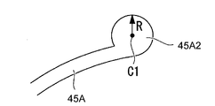
なお、ロータ43は、図10に示すように、溝45Aの溝幅aを半径方向に2分割した中心線上に中心位置C0を配置し、溝先端半径(以下、「半径」と省略する)Rとして描いた円の円弧を溝端部の曲線形状となるようにしてもよい。すなわち、半径をRとする円の円弧から、溝45Aの溝幅aが当接する円弧部分を除いた円弧により円形端部45A1が形成されている。この円形端部45A1は、直径2Rが溝幅aより大きくなる(2R>a)ように設定されており、従って、円形端部45A1は、溝45Aの内周側及び外周側へ均等に膨出する曲線部分を有している。
このような電磁クラッチMのロータ43は、ブリッジ51Aにより分割される溝45Aの端部が、溝幅aより外側へ膨出する部分を有する曲線形状の円形端部45A1として形成されているので、ブリッジ51Aが設けられたブリッジ部の強度を確保しつつ、ブリッジ幅W1を従来よりも狭めることができる。すなわち、エンジン等の外部駆動源からVベルト等を介してプーリー18に動力の伝達を受ける電磁クラッチMにおいては、円形端部45A1がロータ43の外周側から作用する外力に対するブリッジ51Aの応力を分散させるので、ブリッジ幅W1を狭めても強度の低下を防止して強度不足を解消することができる。
この結果、電磁クラッチM及びスクロール型圧縮機10の諸元が同じであれば、円形端部45A1を採用してブリッジ幅W1を狭めても、強度不足によりブリッジ51Aの部分にひびが入る(破損する)ことを防止できる。
従って、ブリッジ幅W1が狭められたことにより、短絡磁束を低減して吸引力を向上させることが可能になる。換言すれば、円形端部45A1を採用してブリッジ幅W1を狭めた電磁クラッチMは、ブリッジ部の強度を維持してアーマチャ42の吸引力を増すことが可能になるので、トルク伝達能力を増加させてアーマチャ42とロータ43との間に生じる滑りのトラブルを防止または抑制することができる。
従って、ブリッジ幅W1が狭められたことにより、短絡磁束を低減して吸引力を向上させることが可能になる。換言すれば、円形端部45A1を採用してブリッジ幅W1を狭めた電磁クラッチMは、ブリッジ部の強度を維持してアーマチャ42の吸引力を増すことが可能になるので、トルク伝達能力を増加させてアーマチャ42とロータ43との間に生じる滑りのトラブルを防止または抑制することができる。
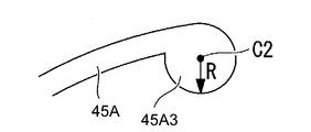
また、たとえば図11に示すように、円中心位置C1を外周側へ移動させた円形端部45A2としてもよし、あるいは、たとえば図12に示すように、円中心位置C2を内周側へ移動させた円形端部45A3としてもよい。
また、溝45Aの端部に形成される曲線形状は、上述した円弧の円形端部45A1,45A2,45A3に限定されることはなく、たとえば溝幅aより幅広となる膨出部を備えた楕円形状なども採用可能である。
また、上述した円形端部45A1,45A2,45A3は、内周側の溝45Aにのみ適用されているが、必要に応じて外周側の溝45Bに採用することも可能である。
また、上述した円形端部45A1,45A2,45A3は、内周側の溝45Aにのみ適用されているが、必要に応じて外周側の溝45Bに採用することも可能である。
10…スクロール型圧縮機(圧縮機)、41…電磁コイル、42…アーマチャ、42a…内周リング、42b…外周リング、43…ロータ、43a…内周リング、43b…中央リング、43c…外周リング、44…溝(中間溝)、45A…溝(内周溝)、45B…溝(外周溝)、46a…ロータ接触面、46b…アーマチャ接触面、100…金属酸化物層、A1…第一接触面、A2…第二接触面、A3…第三接触面、A4…第四接触面、M…電磁クラッチ
Claims (10)
- 電磁コイルの磁力によりアーマチャをロータの接触面に吸引し、前記アーマチャと前記ロータとを一体結合させて動力を伝達する電磁クラッチにおいて、
前記ロータのアーマチャ接触面が、ロータ側溝によって、径方向に分割されるとともに、
前記アーマチャのロータ接触面が、アーマチャ側溝によって、径方向に分割され、
前記ロータ側溝を区画する壁面及び前記アーマチャ側溝を区画する壁面の少なくとも一方の表面に金属酸化物層が形成されていることを特徴とする電磁クラッチ。 - 前記金属酸化物層は0.1μmから10μmの厚さであることを特徴とする請求項1記載の電磁クラッチ。
- 前記ロータ及び前記アーマチャのビッカース硬度が100HV10から350HV10であり、前記金属酸化物層のビッカース硬度が700HV0.003から1200HV0.003であることを特徴とする請求項1に記載の電磁クラッチ。
- 前記アーマチャの前記ロータ接触面に形成された前記溝の幅が0.8~1.2mmとされていることを特徴とする請求項1に記載の電磁クラッチ。
- 圧縮機構の軸部に装着されて動力を伝達する請求項1に記載の電磁クラッチを備えていることを特徴とする圧縮機。
- 圧縮機構の軸部に装着されて動力を伝達する請求項2に記載の電磁クラッチを備えていることを特徴とする圧縮機。
- 圧縮機構の軸部に装着されて動力を伝達する請求項3に記載の電磁クラッチを備えていることを特徴とする圧縮機。
- 圧縮機構の軸部に装着されて動力を伝達する請求項4に記載の電磁クラッチを備えていることを特徴とする圧縮機。
- 電磁コイルの磁力によりアーマチャをロータの接触面に吸引し、前記アーマチャと前記ロータとを一体結合させて動力を伝達し、
前記ロータのアーマチャ接触面が、ロータ側溝によって、径方向に分割されるとともに、
前記アーマチャのロータ接触面が、アーマチャ側溝によって、径方向に分割される電磁クラッチの製造方法において、
レーザ加工により、前記ロータ側溝を区画する壁面及び前記アーマチャ側溝を区画する壁面の少なくとも一方の表面に金属酸化物層を形成することを特徴とする電磁クラッチの製造方法。 - 前記レーザ加工の際に、レーザ光の照射位置に酸素を吹きつけることを特徴とする請求項9に記載の電磁クラッチの製造方法。
Priority Applications (2)
| Application Number | Priority Date | Filing Date | Title |
|---|---|---|---|
| EP10789243.2A EP2444684B1 (en) | 2009-06-18 | 2010-06-17 | Electromagnetic clutch, compressor, and manufacturing method for electromagnetic clutch |
| US13/379,129 US8851259B2 (en) | 2009-06-18 | 2010-06-17 | Electromagnetic clutch, compressor, and manufacturing method for electromagnetic clutch |
Applications Claiming Priority (4)
| Application Number | Priority Date | Filing Date | Title |
|---|---|---|---|
| JP2009145253A JP5473425B2 (ja) | 2009-06-18 | 2009-06-18 | 電磁クラッチ、圧縮機、電磁クラッチの製造方法 |
| JP2009-145252 | 2009-06-18 | ||
| JP2009145252A JP2011002020A (ja) | 2009-06-18 | 2009-06-18 | 電磁クラッチ、圧縮機、電磁クラッチの製造方法 |
| JP2009-145253 | 2009-06-18 |
Publications (1)
| Publication Number | Publication Date |
|---|---|
| WO2010146864A1 true WO2010146864A1 (ja) | 2010-12-23 |
Family
ID=43356194
Family Applications (1)
| Application Number | Title | Priority Date | Filing Date |
|---|---|---|---|
| PCT/JP2010/004049 Ceased WO2010146864A1 (ja) | 2009-06-18 | 2010-06-17 | 電磁クラッチ、圧縮機、電磁クラッチの製造方法 |
Country Status (3)
| Country | Link |
|---|---|
| US (1) | US8851259B2 (ja) |
| EP (1) | EP2444684B1 (ja) |
| WO (1) | WO2010146864A1 (ja) |
Cited By (1)
| Publication number | Priority date | Publication date | Assignee | Title |
|---|---|---|---|---|
| JP2013185643A (ja) * | 2012-03-07 | 2013-09-19 | Denso Corp | 電磁クラッチ |
Families Citing this family (3)
| Publication number | Priority date | Publication date | Assignee | Title |
|---|---|---|---|---|
| JP2013100862A (ja) * | 2011-11-08 | 2013-05-23 | Denso Corp | 電磁クラッチ及びその製造方法 |
| JP6260423B2 (ja) | 2014-04-15 | 2018-01-17 | 株式会社デンソー | クラッチ |
| DE102016204756B4 (de) | 2015-12-23 | 2024-01-11 | OET GmbH | Elektrischer Kältemittelantrieb |
Citations (5)
| Publication number | Priority date | Publication date | Assignee | Title |
|---|---|---|---|---|
| JPS62132039A (ja) * | 1985-12-02 | 1987-06-15 | Inoue Japax Res Inc | 摩擦装置 |
| JP2000291705A (ja) * | 1999-01-25 | 2000-10-20 | Shinko Electric Co Ltd | 摩擦式電磁連結装置 |
| JP2003314584A (ja) | 2002-04-19 | 2003-11-06 | Mitsubishi Heavy Ind Ltd | 電磁クラッチ |
| JP2008280562A (ja) * | 2007-05-09 | 2008-11-20 | National Institute Of Advanced Industrial & Technology | 金属表面加工装置及び方法 |
| JP2009108927A (ja) * | 2007-10-30 | 2009-05-21 | Sanden Corp | 電磁クラッチ |
Family Cites Families (11)
| Publication number | Priority date | Publication date | Assignee | Title |
|---|---|---|---|---|
| US3550739A (en) | 1968-10-25 | 1970-12-29 | Eaton Yale & Towne | Friction coupling |
| DE3675616D1 (de) * | 1985-08-23 | 1990-12-20 | Sanden Corp | Elektromagnetisch betaetigte kupplungen. |
| JPS6249025A (ja) * | 1985-08-27 | 1987-03-03 | Sanden Corp | 電磁クラツチ |
| JPS6246029A (ja) * | 1985-08-23 | 1987-02-27 | Sanden Corp | 電磁クラツチ |
| JPS63252687A (ja) * | 1987-04-09 | 1988-10-19 | Mitsubishi Electric Corp | レ−ザ加工ヘツド |
| US4749073A (en) | 1987-05-11 | 1988-06-07 | Dana Corporation | Soft-start electromagnetic coupling |
| US4951797A (en) | 1988-10-25 | 1990-08-28 | Dana Corporation | Electromagnetic coupling disc |
| US5642798A (en) * | 1996-03-22 | 1997-07-01 | General Motors Corporation | Electromagentic compressor clutch with combined torque cushion and armature cooling |
| US6364084B1 (en) * | 2000-02-29 | 2002-04-02 | Warner Electric Technology, Inc. | Armature for a selectively engageable and disengageable coupling |
| EP1354638A3 (en) * | 2002-04-15 | 2004-11-03 | Fuji Photo Film Co., Ltd. | Method and apparatus for manufacturing pattern members using webs on which coating films have been formed |
| JP2004052985A (ja) * | 2002-07-24 | 2004-02-19 | Zexel Valeo Climate Control Corp | 電磁クラッチ |
-
2010
- 2010-06-17 WO PCT/JP2010/004049 patent/WO2010146864A1/ja not_active Ceased
- 2010-06-17 EP EP10789243.2A patent/EP2444684B1/en not_active Not-in-force
- 2010-06-17 US US13/379,129 patent/US8851259B2/en not_active Expired - Fee Related
Patent Citations (5)
| Publication number | Priority date | Publication date | Assignee | Title |
|---|---|---|---|---|
| JPS62132039A (ja) * | 1985-12-02 | 1987-06-15 | Inoue Japax Res Inc | 摩擦装置 |
| JP2000291705A (ja) * | 1999-01-25 | 2000-10-20 | Shinko Electric Co Ltd | 摩擦式電磁連結装置 |
| JP2003314584A (ja) | 2002-04-19 | 2003-11-06 | Mitsubishi Heavy Ind Ltd | 電磁クラッチ |
| JP2008280562A (ja) * | 2007-05-09 | 2008-11-20 | National Institute Of Advanced Industrial & Technology | 金属表面加工装置及び方法 |
| JP2009108927A (ja) * | 2007-10-30 | 2009-05-21 | Sanden Corp | 電磁クラッチ |
Non-Patent Citations (1)
| Title |
|---|
| See also references of EP2444684A4 * |
Cited By (1)
| Publication number | Priority date | Publication date | Assignee | Title |
|---|---|---|---|---|
| JP2013185643A (ja) * | 2012-03-07 | 2013-09-19 | Denso Corp | 電磁クラッチ |
Also Published As
| Publication number | Publication date |
|---|---|
| US8851259B2 (en) | 2014-10-07 |
| EP2444684A1 (en) | 2012-04-25 |
| EP2444684A4 (en) | 2012-12-12 |
| EP2444684B1 (en) | 2014-05-21 |
| US20120156062A1 (en) | 2012-06-21 |
Similar Documents
| Publication | Publication Date | Title |
|---|---|---|
| JP6187123B2 (ja) | スクロール型圧縮機 | |
| EP2803860A1 (en) | Scroll compressor | |
| WO2010146864A1 (ja) | 電磁クラッチ、圧縮機、電磁クラッチの製造方法 | |
| EP3567213B1 (en) | Scroll compressor | |
| JP5473425B2 (ja) | 電磁クラッチ、圧縮機、電磁クラッチの製造方法 | |
| JP6053349B2 (ja) | スクロール圧縮機 | |
| JP2011074884A (ja) | スクロール流体機械 | |
| JP5166803B2 (ja) | スクロール圧縮機 | |
| CN103842680B (zh) | 电磁离合器及电磁离合器的电枢制造方法 | |
| JP2011149376A (ja) | スクロール圧縮機 | |
| JP2006283694A (ja) | スクロール型流体機械 | |
| WO2017141703A1 (ja) | スクロール圧縮機 | |
| JPH09112454A (ja) | スクロール型圧縮機用ボトムプレート | |
| JP2011002020A (ja) | 電磁クラッチ、圧縮機、電磁クラッチの製造方法 | |
| JP6017269B2 (ja) | スクロール圧縮機 | |
| WO2019078293A1 (ja) | ロータリ圧縮機の回転軸、及び、ロータリ圧縮機 | |
| WO2011052166A1 (ja) | スクロール型流体機械 | |
| JP2013024051A (ja) | スクロール圧縮機 | |
| JP5979974B2 (ja) | スクロール圧縮機およびその設計方法 | |
| JPS58117376A (ja) | スクロ−ル型流体機械 | |
| JP3424506B2 (ja) | スクロール流体機械 | |
| JP2007064163A (ja) | ベーン型圧縮機 | |
| JPH08159052A (ja) | スクロール圧縮機 | |
| JP4868446B2 (ja) | スクロール部材およびそれを用いたスクロール流体機械 | |
| JP2010203480A (ja) | 電磁クラッチ及びこれを備えた圧縮機 |
Legal Events
| Date | Code | Title | Description |
|---|---|---|---|
| 121 | Ep: the epo has been informed by wipo that ep was designated in this application |
Ref document number: 10789243 Country of ref document: EP Kind code of ref document: A1 |
|
| WWE | Wipo information: entry into national phase |
Ref document number: 2010789243 Country of ref document: EP |
|
| NENP | Non-entry into the national phase |
Ref country code: DE |
|
| WWE | Wipo information: entry into national phase |
Ref document number: 13379129 Country of ref document: US |