WO2010146864A1 - Embrayage électromagnétique, compresseur et procédé de fabrication pour embrayage électromagnétique - Google Patents
Embrayage électromagnétique, compresseur et procédé de fabrication pour embrayage électromagnétique Download PDFInfo
- Publication number
- WO2010146864A1 WO2010146864A1 PCT/JP2010/004049 JP2010004049W WO2010146864A1 WO 2010146864 A1 WO2010146864 A1 WO 2010146864A1 JP 2010004049 W JP2010004049 W JP 2010004049W WO 2010146864 A1 WO2010146864 A1 WO 2010146864A1
- Authority
- WO
- WIPO (PCT)
- Prior art keywords
- armature
- rotor
- contact surface
- electromagnetic clutch
- groove
- Prior art date
- Legal status (The legal status is an assumption and is not a legal conclusion. Google has not performed a legal analysis and makes no representation as to the accuracy of the status listed.)
- Ceased
Links
Images


Classifications
-
- F—MECHANICAL ENGINEERING; LIGHTING; HEATING; WEAPONS; BLASTING
- F16—ENGINEERING ELEMENTS AND UNITS; GENERAL MEASURES FOR PRODUCING AND MAINTAINING EFFECTIVE FUNCTIONING OF MACHINES OR INSTALLATIONS; THERMAL INSULATION IN GENERAL
- F16D—COUPLINGS FOR TRANSMITTING ROTATION; CLUTCHES; BRAKES
- F16D27/00—Magnetically- or electrically- actuated clutches; Control or electric circuits therefor
- F16D27/10—Magnetically- or electrically- actuated clutches; Control or electric circuits therefor with an electromagnet not rotating with a clutching member, i.e. without collecting rings
- F16D27/108—Magnetically- or electrically- actuated clutches; Control or electric circuits therefor with an electromagnet not rotating with a clutching member, i.e. without collecting rings with axially movable clutching members
- F16D27/112—Magnetically- or electrically- actuated clutches; Control or electric circuits therefor with an electromagnet not rotating with a clutching member, i.e. without collecting rings with axially movable clutching members with flat friction surfaces, e.g. discs
-
- F—MECHANICAL ENGINEERING; LIGHTING; HEATING; WEAPONS; BLASTING
- F04—POSITIVE - DISPLACEMENT MACHINES FOR LIQUIDS; PUMPS FOR LIQUIDS OR ELASTIC FLUIDS
- F04C—ROTARY-PISTON, OR OSCILLATING-PISTON, POSITIVE-DISPLACEMENT MACHINES FOR LIQUIDS; ROTARY-PISTON, OR OSCILLATING-PISTON, POSITIVE-DISPLACEMENT PUMPS
- F04C29/00—Component parts, details or accessories of pumps or pumping installations, not provided for in groups F04C18/00 - F04C28/00
- F04C29/0042—Driving elements, brakes, couplings, transmissions specially adapted for pumps
- F04C29/005—Means for transmitting movement from the prime mover to driven parts of the pump, e.g. clutches, couplings, transmissions
-
- F—MECHANICAL ENGINEERING; LIGHTING; HEATING; WEAPONS; BLASTING
- F16—ENGINEERING ELEMENTS AND UNITS; GENERAL MEASURES FOR PRODUCING AND MAINTAINING EFFECTIVE FUNCTIONING OF MACHINES OR INSTALLATIONS; THERMAL INSULATION IN GENERAL
- F16D—COUPLINGS FOR TRANSMITTING ROTATION; CLUTCHES; BRAKES
- F16D27/00—Magnetically- or electrically- actuated clutches; Control or electric circuits therefor
- F16D27/02—Magnetically- or electrically- actuated clutches; Control or electric circuits therefor with electromagnets incorporated in the clutch, i.e. with collecting rings
- F16D27/04—Magnetically- or electrically- actuated clutches; Control or electric circuits therefor with electromagnets incorporated in the clutch, i.e. with collecting rings with axially-movable friction surfaces
- F16D27/06—Magnetically- or electrically- actuated clutches; Control or electric circuits therefor with electromagnets incorporated in the clutch, i.e. with collecting rings with axially-movable friction surfaces with friction surfaces arranged within the flux
-
- F—MECHANICAL ENGINEERING; LIGHTING; HEATING; WEAPONS; BLASTING
- F04—POSITIVE - DISPLACEMENT MACHINES FOR LIQUIDS; PUMPS FOR LIQUIDS OR ELASTIC FLUIDS
- F04C—ROTARY-PISTON, OR OSCILLATING-PISTON, POSITIVE-DISPLACEMENT MACHINES FOR LIQUIDS; ROTARY-PISTON, OR OSCILLATING-PISTON, POSITIVE-DISPLACEMENT PUMPS
- F04C18/00—Rotary-piston pumps specially adapted for elastic fluids
- F04C18/02—Rotary-piston pumps specially adapted for elastic fluids of arcuate-engagement type, i.e. with circular translatory movement of co-operating members, each member having the same number of teeth or tooth-equivalents
- F04C18/0207—Rotary-piston pumps specially adapted for elastic fluids of arcuate-engagement type, i.e. with circular translatory movement of co-operating members, each member having the same number of teeth or tooth-equivalents both members having co-operating elements in spiral form
- F04C18/0215—Rotary-piston pumps specially adapted for elastic fluids of arcuate-engagement type, i.e. with circular translatory movement of co-operating members, each member having the same number of teeth or tooth-equivalents both members having co-operating elements in spiral form where only one member is moving
-
- F—MECHANICAL ENGINEERING; LIGHTING; HEATING; WEAPONS; BLASTING
- F16—ENGINEERING ELEMENTS AND UNITS; GENERAL MEASURES FOR PRODUCING AND MAINTAINING EFFECTIVE FUNCTIONING OF MACHINES OR INSTALLATIONS; THERMAL INSULATION IN GENERAL
- F16D—COUPLINGS FOR TRANSMITTING ROTATION; CLUTCHES; BRAKES
- F16D27/00—Magnetically- or electrically- actuated clutches; Control or electric circuits therefor
- F16D2027/008—Details relating to the magnetic circuit, or to the shape of the clutch parts to achieve a certain magnetic path
-
- F—MECHANICAL ENGINEERING; LIGHTING; HEATING; WEAPONS; BLASTING
- F16—ENGINEERING ELEMENTS AND UNITS; GENERAL MEASURES FOR PRODUCING AND MAINTAINING EFFECTIVE FUNCTIONING OF MACHINES OR INSTALLATIONS; THERMAL INSULATION IN GENERAL
- F16D—COUPLINGS FOR TRANSMITTING ROTATION; CLUTCHES; BRAKES
- F16D2300/00—Special features for couplings or clutches
- F16D2300/10—Surface characteristics; Details related to material surfaces
-
- Y—GENERAL TAGGING OF NEW TECHNOLOGICAL DEVELOPMENTS; GENERAL TAGGING OF CROSS-SECTIONAL TECHNOLOGIES SPANNING OVER SEVERAL SECTIONS OF THE IPC; TECHNICAL SUBJECTS COVERED BY FORMER USPC CROSS-REFERENCE ART COLLECTIONS [XRACs] AND DIGESTS
- Y10—TECHNICAL SUBJECTS COVERED BY FORMER USPC
- Y10T—TECHNICAL SUBJECTS COVERED BY FORMER US CLASSIFICATION
- Y10T29/00—Metal working
- Y10T29/49—Method of mechanical manufacture
- Y10T29/49002—Electrical device making
- Y10T29/4902—Electromagnet, transformer or inductor
Definitions
- the present invention relates to an electromagnetic clutch that is applied to, for example, a vehicle air conditioner and transmits power, a compressor including the electromagnetic clutch, and a method for manufacturing the electromagnetic clutch.
- a compressor used in a vehicle air conditioner includes an electromagnetic clutch that is disposed between a drive source and transmits power.
- the electromagnetic clutch can be selected by transmitting or not transmitting power by electromagnetic force.
- the armature 2 is attracted to the rotor 3 by the magnetic force of the electromagnetic coil 1 as shown in FIG.
- the rotor 3 are integrally coupled to transmit power (see, for example, Patent Document 1).
- the radial width of the armature 2 is divided into two parts, and the radial width of the rotor 3 is divided into three parts, so that the contact surface (gap) 4 between the armature 2 and the rotor 3 is in the radial direction. Divided into four.
- the contact surface 4 on the rotor 3 side is referred to as an armature contact surface 4a
- the contact surface 4 on the armature 2 side is referred to as a rotor contact surface 4b.
- the armature contact surface 4a of the rotor 3 is divided into three radial directions by two grooves 5 having a groove width a as shown in FIG. 6 (a), for example, an inner ring 3a, a center ring 3b, An outer ring 3c is formed.
- the two grooves 5 are divided at a plurality of locations in the circumferential direction by a bridge 6 that connects the inner ring 3a, the center ring 3b, and the outer ring 3c.
- the armature 2 is divided into an inner peripheral portion 2a and an outer peripheral portion 2b by a groove 7 having a groove width b.
- the armature 2 in this case is composed of a plate punched from a plate material by punching.
- the present invention has been made on the basis of such a technical problem, and an electromagnetic clutch capable of increasing the frictional force between the armature and the rotor without increasing the outer dimension of the battery clutch. It is an object of the present invention to provide a compressor and a method for manufacturing the electromagnetic clutch.
- the present invention made for this purpose is an electromagnetic clutch in which the armature is attracted to the contact surface of the rotor by the magnetic force of the electromagnetic coil, and the armature and the rotor are integrally coupled to transmit power.
- the rotor side groove is divided in the radial direction, and the rotor contact surface of the armature is divided by the armature side groove, and a metal oxide layer is formed on at least one surface of the wall surface defining the rotor side groove and the wall surface defining the armature side groove. It is formed.
- the metal oxide layer formed on the wall surface defining the rotor side groove is abbreviated as the rotor side oxide layer
- the metal oxide layer formed on the wall surface defining the armature side groove is abbreviated as the armature side oxide layer.
- the armature contact surface of the rotor and the rotor contact surface of the armature are slidably contacted and worn, and accordingly, the armature-side oxide is formed on the armature contact surface of the rotor.
- the layers are in sliding contact, and the rotor side oxide layer is in sliding contact with the rotor contact surface of the armature. Therefore, a part of these metal oxide layers is crushed or peeled (hereinafter collectively referred to as crushed) to produce metal oxide particles, which are supplied to the armature contact surface of the rotor or the rotor contact surface of the armature. . Accordingly, it is possible to suppress slippage by increasing the frictional force between the armature and the rotor without increasing the outer dimension.
- the metal oxide layer preferably has a thickness of 0.1 ⁇ m to 10 ⁇ m. Furthermore, it is preferable that the Vickers hardness of the rotor and the armature is 100HV10 to 350HV10, and the Vickers hardness of the metal oxide layer is 700HV0.003 to 1200HV0.003. As described above, since the Vickers hardness of the metal oxide layer is high, particles generated from the metal oxide layer enter between the armature and the rotor that are in contact with each other by a suction force, and the space between the armature and the rotor is reduced. The frictional force can be increased and slippage can be suppressed.
- the width of the groove formed on the rotor contact surface of the armature is 0.8 to 1.2 mm.
- the compressor according to the present invention can be provided with the above-described electromagnetic clutch so as to be mounted on the shaft portion of the compression mechanism and transmit power.
- the armature is attracted to the contact surface of the rotor by the magnetic force of the electromagnetic coil, and the armature and the rotor are integrally coupled to transmit power, and the armature contact surface of the rotor is
- the wall surface defining the rotor side groove and the wall surface defining the armature side groove are formed by laser processing.
- a metal oxide layer is formed on at least one surface.
- the metal oxide layer when forming at least one of the rotor side groove and the armature side groove by laser processing for forming the metal oxide. Further, during the laser processing, it is preferable to blow oxygen to the irradiation position of the laser beam, that is, the rotor side groove or the armature side groove.
- fine grooves (rotor side grooves, armature side grooves) can be formed in the armature and the rotor, and heat generated by laser light irradiation can be used to form the grooves.
- a metal oxide layer can be easily formed simultaneously with the formation. Further, when oxygen gas is blown to the laser irradiation position, melting of the cut portion is promoted by oxidation reaction heat, so that the groove processing speed can be increased.
- the armature-side oxide layer slidably in contact with the armature contact surface of the rotor and the rotor-side oxide layer slidably in contact with the rotor contact surface of the armature become particles, and the armature of the rotor Supplied to the contact surface and the rotor contact surface of the armature.
- the frictional force between the armature and the rotor can be increased and slippage can be suppressed.
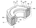
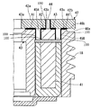
- FIG. 1 It is a longitudinal section showing an example of composition of a scroll type compressor provided with an electromagnetic clutch in this embodiment. It is a perspective sectional view of an electromagnetic clutch.
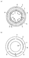
- (A) is a top view of an armature
- (b) is a top view of a rotor. It is an expanded sectional view which shows the contact part of an armature and a rotor.
- (A) is a top view of the conventional rotor
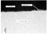
- (b) is a top view of the conventional armature. It is a cross-sectional photograph of the groove part of an armature.
- FIG. 1 is a longitudinal sectional view showing a configuration example of a scroll compressor provided with an electromagnetic clutch.
- the scroll compressor (compressor) 10 includes a front housing 11 and a rear housing 12, and includes a housing 13 in which the front housing 11 and the rear housing 12 are integrally fastened and fixed by bolts (not shown). ing.
- crankshaft (rotary shaft) 14 is rotatably supported around a rotation axis L via a main bearing (needle bearing) 15 and a sub-bearing (needle bearing) 16.
- One end side (the left side in FIG. 1) of the crankshaft 14 is a small diameter shaft portion 14a, and the small diameter shaft portion 14a penetrates the front housing 11 and protrudes to one end side.
- An electromagnetic clutch M is mounted on the protruding portion of the small-diameter shaft portion 14a, and between the pulley 18 provided rotatably on the outer peripheral surface of the small-diameter boss portion 11a on one end side of the front housing 11 via a bearing 17.
- the power is intermittent.
- Power is transmitted to the pulley 18 from an external drive source such as an engine (not shown) via a V-belt or the like.
- an external drive source such as an engine (not shown) via a V-belt or the like.
- a mechanical seal (lip seal) 19 is provided between the main bearing 15 and the sub-bearing 16, thereby hermetically sealing the inside of the housing 13 and the atmosphere.
- a large-diameter shaft portion 14 b is provided on the other end side (right side in FIG. 1) of the crankshaft 14, and the large-diameter shaft portion 14 b has a predetermined dimension from the rotation axis L of the crankshaft 14.
- An eccentric pin 14c is integrally provided in an eccentric state.
- the large-diameter shaft portion 14b and the small-diameter shaft portion 14a of the crankshaft 14 are rotatably supported by the front housing 11 via the main bearing 15 and the sub bearing 16, respectively.
- the orbiting scroll member 22 is connected to the eccentric pin 14c via the balance bush 20 and the drive bearing 21, and the orbiting scroll member 22 is driven to rotate by rotating the crankshaft 14. It has become.
- the balance bush 20 is formed with a balance weight 20a for removing an unbalanced load generated when the orbiting scroll member 22 is orbitally driven.
- the balance weight 20a is orbited when the orbiting scroll member 22 is orbitally driven.
- a pair of fixed scroll portions 24 and a turning scroll member 22 constituting a scroll type compression mechanism 23 are incorporated.
- the fixed scroll member 24 includes a fixed end plate 24a and a spiral wrap 24b erected from the fixed end plate 24a.
- the orbiting scroll member 22 includes the orbiting end plate 22a and the orbiting end plate. And a spiral wrap 22b erected from 22a.
- the fixed scroll member 24 and the orbiting scroll member 22 are assembled in such a state that the centers of the fixed scroll member 24 and the orbiting scroll member 22 are separated by the orbiting radius, and the spiral wraps 24b and 22b are engaged with each other with a phase difference of 180 degrees.
- a pair of compression chambers C defined by the end plates 24a and 22a and the spiral wraps 24b and 22b are formed symmetrically between the scroll members 24 and 22 with respect to the center of the scroll. Will be.
- the fixed scroll member 24 is fixed to the inner surface (bottom surface) of the rear housing 12 via a bolt 25.
- an eccentric pin 14 c provided on one end side of the crankshaft 14 is fitted into a boss portion 26 provided on the back surface of the orbiting end plate 22 a via a balance bush 20 and a drive bearing 21.
- the crankshaft 14 is connected.
- the orbiting scroll member 22 has a thrust receiving surface 11b formed on the front housing 11 supported on the back surface of the orbiting end plate 22a, and the orbiting scroll member 22 is interposed between the thrust receiving surface 11b and the orbiting scroll member 22 on the back surface.
- the orbiting scroll member 22 is configured to be revolved and driven with respect to the fixed scroll member 24 while being prevented from rotating by the rotation-preventing pinning mechanism 27 mounted.
- This rotation-preventing pin ring mechanism 27 includes a pin 27a and a ring 27b, and a pin hole 11c for standing the pin 27a on one of the back surface of the fixed end plate 22a of the orbiting scroll member 22 and the thrust receiving surface 11b is provided on the other side. Is provided with a ring hole 22c for fitting the ring 27b.
- the thrust receiving surface 11 b is provided with a pin hole 11 c for standing the pin 27 a
- the orbiting scroll member 22 is provided with a ring hole 22 c for fitting the ring 27 b.
- the pin holes 11c and the ring holes 22c are provided at a plurality of locations in the circumferential direction, generally 3 to 4 locations (4 locations in the present embodiment).
- a discharge port 24c for discharging compressed refrigerant gas is opened at the center of the fixed end plate 24a of the fixed scroll member 24.
- the discharge port 24c is connected to the fixed end plate 24a via a retainer 28.
- a discharge reed valve (not shown) is provided.
- a seal member (not shown) such as an O-ring is installed on the back surface of the fixed end plate 24 a of the fixed scroll member 24 so as to be in close contact with the inner surface of the rear housing 12.
- a discharge chamber 29 partitioned from the internal space (sealed space) is formed. Thereby, the internal space of the housing 13 excluding the discharge chamber 29 functions as the suction chamber 30.
- Refrigerant gas returning from the refrigeration cycle is sucked into the suction chamber 30 via a suction port (not shown) provided in the front housing 11, and the fixed scroll member 24 and the orbiting scroll member are passed through the suction chamber 30.
- the refrigerant gas is sucked into the compression chamber C formed between the two.
- a sealing member 31 such as an O-ring is installed on the joint surface between the front housing 11 and the rear housing 12, and the suction chamber 30 in the housing 13 is hermetically sealed from the atmosphere.
- the scroll compressor 10 configured as described above operates as follows.
- the rotational driving force transmitted from the external drive source to the pulley 18 is transmitted to the crankshaft 14 via the electromagnetic clutch M, and the crankshaft 14 is rotated.
- the orbiting scroll member 22 connected to the eccentric pin 14c of the crankshaft 14 via the balance bush 20 and the drive bearing 21 is prevented from rotating by the rotation preventing pin ring mechanism 27 while being rotated against the fixed scroll member 24. Revolved and driven.
- the revolving orbiting drive of the orbiting scroll member 22 causes the refrigerant gas in the suction chamber 30 to be sucked into the compression chamber C formed at the radially outermost side.
- the compression chamber C is closed by suction at a predetermined swivel angle position, the compression chamber C is moved to the center side while the volume is reduced in the circumferential direction and the lap height direction.
- the refrigerant gas is compressed, and when the compression chamber C reaches a position where it communicates with the discharge port 24c, the discharge reed valve is pushed open and the compressed gas is discharged into the discharge chamber 29. It is discharged out of the compressor through a discharge port (not shown) provided in the rear housing 12.
- the scroll compressor 10 described above includes an electromagnetic clutch M that is mounted on the crankshaft 14 of the compression mechanism and transmits power.
- the electromagnetic clutch M attracts the magnetic armature 42 to the contact surface of the rotor 43 by the magnetic force of the electromagnetic coil 41, and transmits the power by integrally coupling the armature 42 and the rotor 43.
- the radial direction of the armature 42 is divided into two by a groove (intermediate groove) 44 having a width b, and an inner ring 42a, An outer peripheral ring 42b is formed.
- the groove 44 is divided at a plurality of locations in the circumferential direction by a bridge 50 that connects the inner ring 42a and the outer ring 42b.
- the grooves 44 divided by the bridge 50 each form an arc having the same width with the groove width being b.
- channels 45A and 45B demonstrated below are formed by laser processing.
- the electromagnetic clutch M of the present embodiment includes two grooves (inner circumferential grooves) 45A and grooves (outer circumferences) in which the radial direction of the rotor 43 has a width a.
- Groove) 45B and is divided into three to form an inner ring 43a, a center ring 43b, and an outer ring 43c.
- the two grooves 45A and 45B are divided at a plurality of locations in the circumferential direction by bridges 51A and 51B connecting the inner ring 43a, the center ring 43b, and the outer ring 43c.
- the grooves 45A and 45B divided by the bridges 51A and 51B each form an arc having the same width with the groove width being a.
- the width of the grooves 44, 45A and 45B is preferably 0.8 to 1.2 mm. This is because the contact area between the rotor and the armature can be increased without increasing the size of the electromagnetic clutch itself, and the occurrence of a short circuit in the magnetic flux on both sides of the grooves 44, 45A and 45B can be suppressed.
- the grooves 44, 45 ⁇ / b> A and 45 ⁇ / b> B formed in this way allow the rotor contact surface 46 a of the armature 42 and the armature contact surface 46 b of the rotor 43 to be connected to the inner peripheral ring 43 a of the rotor 43.
- An annular first contact surface A1 facing the inner ring 42a, an annular second contact surface A2 where the inner ring 42a of the armature 42 faces the center ring 43b of the rotor 43, and an outer ring 42b of the armature 42 are the rotor.
- the annular third contact surface A3 facing the central ring 43b of 43 and the annular fourth contact surface A4 of the outer ring 43c of the rotor 43 facing the outer ring 42b of the armature 42 generate a suction force.
- the first contact surface A1, the second contact surface A2, the third contact surface A3, and the fourth contact surface A4 are configured so that the areas of the annular areas are substantially equal to each other so that the suction force is equalized. It is preferable to form the grooves 44, 45A, 45B. Further, in order to increase the force against the rotational torque when the armature 42 and the rotor 43 are attracted to each other, of the first contact surface A1, the second contact surface A2, the third contact surface A3, and the fourth contact surface A4, The area of the fourth contact surface A4 on the outer periphery may be maximized.
- a metal oxide layer 100 is formed on the surface of the wall surface that partitions each of the grooves 44, 45A, 45B.
- the metal oxide layer 100 formed on the wall surface defining the groove 44 is formed from the upper end edge to the lower end edge of the groove 44.
- the portion formed at the lower edge of the metal oxide layer 100 is in contact with the second contact surface A2 and the third contact surface A3.
- the metal oxide layer 100 formed on the wall surface defining the groove 45A is formed from the upper end edge to the lower end edge of the groove 45A.
- the portion formed at the upper edge of the metal oxide layer 100 is in contact with the first contact surface A1 and the second contact surface A2.
- the metal oxide layer 100 formed on the wall surface defining the groove 45B is formed from the upper end edge to the lower end edge of the groove 45B.
- the portion formed at the upper edge of the metal oxide layer 100 is in contact with the third contact surface A3 and the fourth contact surface A4.
- the metal oxide layer 100 may be provided with a thickness of 0.1 ⁇ m to 10 ⁇ m. However, as will be described later, the metal oxide layer 100 is preferably 0.5 to 3 ⁇ m thick.
- FIG. 7 shows a cross-sectional photograph of the vicinity of the groove 44 of the armature 42. In order to form the metal oxide layer 100 shown in FIG.
- a 4.5 mm thick mild steel material (SPHC: hot rolled steel plate) was used to form grooves at a speed of 3.5 m / min using a CO 2 laser with an output of 2500 W. 44 was processed and formed.
- a metal oxide layer 100 having a thickness of about 0.5 ⁇ m to 3 ⁇ m is attached to the surface of the wall surface defining the groove 44 of the armature 42. This is because the metal oxide particles generated by being crushed from the metal oxide layer 100 by the sliding contact between the armature 42 and the rotor 43 are likely to be about 0.1 ⁇ m to 1 ⁇ m.
- the metal oxide layer 100 is not attached to the surface of the groove 44.
- the metal oxide layer is provided with a thickness of about 1 ⁇ m.
- the object of the present invention can be achieved if a part of the metal oxide layer is deposited with a thickness of 0.1 ⁇ m to 10 ⁇ m.
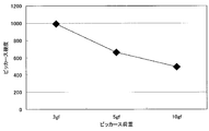
- FIG. 8 shows the result of measuring the surface of the metal oxide layer 100 shown in FIG. 7 by micro Vickers.
- the load was 3 gf
- the Vickers hardness was about 1000 (in the present specification, it is shown as 1000 HV0.003, and the others are the same), and the values were about 650HV0.005 and 500HV0.010. This is because when the load becomes heavy, the mild steel material on the surface of the armature also affects the measured value.
- the Vickers hardness of the armature 42 may be 100 HV10 to 350 HV10, and the laser light may be irradiated so that the Vickers hardness of the metal oxide layer 100 is 700 HV0.003 to 1200 HV0.003.
- the most preferable Vickers hardness of the metal oxide layer 100 is about 1000 ⁇ 100HV0.003.
- the metal oxide layer 100 is not called hydrous iron oxide Fe 2 O 3 H 2 O but a triiron tetroxide (Fe 3 O 4 ) generated by high-temperature oxidation and is commonly called “black skin”. Is.
- the rotor contact surface 46a and the armature contact surface 46b are in sliding contact with each other at the first contact surface A1, the second contact surface A2, the third contact surface A3, and the fourth contact surface A4. Wear.
- the metal oxide layer 100 facing the lower end edge of the groove 44 formed on the wall surface defining the groove 44 is in sliding contact with the second contact surface A2 and the third contact surface A3, and is crushed into fine particles. .
- the groove 45A is slid with the first contact surface A1 and the second contact surface A2, and the groove 45B is slid with the third contact surface A3 and the fourth contact surface A4. By the contact, particles are generated from the metal oxide layer 100.
- the fine particles generated from the metal oxide layer 100 have a particle size of, for example, about 0.1 to 1 ⁇ m, and the first contact surface A1, the second contact surface A2, the third contact surface A3, and the fourth contact. Enter surface A4. Since the metal oxide layer 100 is formed from the upper end edge to the lower end edge of the grooves 44, 45A, 45B, as long as the electromagnetic clutch M is used, the particles can be continuously supplied to the contact surface.
- the first contact surface A1, the second contact surface A2, the third contact surface A3, and the fourth contact surface A4 enter the first contact surface A1, the second contact surface A2, and the fourth contact surface A4.
- Particles (hereinafter referred to as metal oxide particles) generated from the metal oxide layer 100 that have entered the respective contact surfaces A1 to A4 function as resistance at the contact surfaces, and the frictional force between the rotor 43 and the armature 42. And the slip between the rotor 43 and the armature 42 can be suppressed.
- the metal oxide particles are successively supplied as the rotor 43 and the armature 42 are worn, the metal oxide particles can be constantly supplied between the rotor 43 and the armature 42.
- the metal oxide layer 100 can achieve the above-described effects even if it is formed in any one of the grooves 44, 45A, and 45B.
- the grooves 44, 45A, 45B are formed by laser processing.
- laser processing the plate material is cut (fused) into a predetermined shape by moving the laser beam, the armature 42, and the rotor 43 relative to each other while irradiating the plate material forming the armature 42 and the rotor 43 with laser light.
- the grooves 44, 45A and 45B are formed.
- the metal oxide layer 100 can be formed only by laser light irradiation, more preferably, oxygen is blown to the laser irradiation light position. Thereby, the metal oxide layer 100 can be formed efficiently. Blowing oxygen also increases the cutting speed.
- the second contact surface A2 and the third contact located on both sides of the groove 44 of the armature 42.
- the area of one or both of the surfaces A3 tends to be the smallest. Therefore, the area of the second contact surface A2 and the third contact surface A3 is 11% or more with respect to the total area A0 between the inner diameter side of the first contact surface A1 and the outer diameter side of the fourth contact surface A4. It is preferable to form so as to occupy.
- the area of the second contact surface A2 is 11% to 14% with respect to the total area A0, and the area of the third contact surface A3 is 12% to 15% with respect to the total area A0.
- the area of the second contact surface A2 or the third contact surface A3 having the smallest area among the contact surface A1, the second contact surface A2, the third contact surface A3, and the fourth contact surface A4 is more than a certain value.
- the groove 44 positioned between the second contact surface A2 and the third contact surface A3 having the smallest area has a width b of 0.
- the thickness is preferably 5 to 1.5 mm, and more preferably 0.8 to 1.2 mm.
- the width b of the groove 44 is set smaller than the width a of the grooves 45A and 45B.
- the width b of the groove 44 can be made equal to the width a of the grooves 45A and 45B.
- the width b of the groove 44 can be set smaller than the sum of the width a of the groove 45A and the width a of the groove 45B.
- the widths a, b of the grooves 44, 45A, 45B are set as low as possible within a range that does not cause a short circuit of magnetic flux at low cost. be able to.
- the pressure-bonding area between the armature 42 and the rotor 43 can be increased without increasing the size of the armature 42 and the rotor 43, and the mutual suction force can be increased.
- the torque transmission capability of the electromagnetic clutch M can be increased, and the scroll compressor 10 can be increased in torque.
- the inner peripheral surfaces of the grooves 44, 45A, 45B are hardened by heat input by the laser beam, and the hardness of the base material of the armature 42 and the rotor 43 is increased. It is larger than the hardness. As a result, it is possible to increase the strength of the wall surfaces that define the grooves 44, 45A, 45B.
- the above-described armature 42 and rotor 43 may be made of, for example, mild steel such as SPHC (hot rolled steel plate), SPCC (cold rolled steel plate), or low carbon steel such as S12C. This is because the steel material increases in hardness when the carbon content is increased, but on the other hand, the ferrite phase decreases and the magnetic flux density (magnetic permeability) of the electromagnetic clutch decreases.
- mild steel such as SPHC (hot rolled steel plate), SPCC (cold rolled steel plate), or low carbon steel such as S12C.
- the armature 42 and the rotor 43 are made of a steel material such as carbon steel, and have an annular shape with an outer diameter of 110 mm and an inner diameter of 65 mm.
- the width b of the groove 44 of the armature 42 is changed to 0.5, 0.8, 1.0, 1.2, 1.5, 2.2 (current) mm.
- the ratio of the attractive force between the armature 42 and the rotor 43 when a magnetic field was generated by the electromagnetic coil 41 under the same conditions was obtained by simulation using an electronic computer.
- the configuration of the scroll compressor 10 has been described.
- the configuration of other parts other than the configuration related to the main part of the present invention is not limited at all.
- the configuration described in the above embodiment can be selected or changed to another configuration as appropriate.
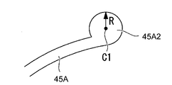
- the rotor 43 has a center position C0 on a center line obtained by dividing the groove width a of the groove 45A into two in the radial direction, and a groove tip radius (hereinafter abbreviated as “radius”) R.
- the circular arc drawn as may be a curved shape at the end of the groove. That is, the circular end 45A1 is formed by an arc obtained by excluding an arc portion where the groove width a of the groove 45A abuts from an arc of a circle having a radius R.
- the circular end 45A1 is set so that the diameter 2R is larger than the groove width a (2R> a). Therefore, the circular end 45A1 bulges evenly toward the inner and outer peripheral sides of the groove 45A. It has a curved part to do.
- the rotor 43 of such an electromagnetic clutch M is formed as a circular end 45A1 having a curved shape, the end of the groove 45A divided by the bridge 51A bulges outside the groove width a. While ensuring the strength of the bridge portion provided with the bridge 51 ⁇ / b> A, the bridge width W ⁇ b> 1 can be made narrower than before. That is, in the electromagnetic clutch M that receives power transmitted from an external drive source such as an engine to the pulley 18 via a V-belt or the like, the circular end 45A1 disperses the stress of the bridge 51A against the external force acting from the outer peripheral side of the rotor 43. Therefore, even if the bridge width W1 is narrowed, the strength is prevented from decreasing and the lack of strength can be solved.
- the electromagnetic clutch M that employs the circular end 45A1 to narrow the bridge width W1 can increase the attractive force of the armature 42 while maintaining the strength of the bridge portion, thereby increasing the torque transmission capability.
- slipping troubles occurring between the armature 42 and the rotor 43 can be prevented or suppressed.
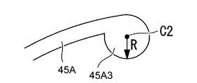
- the circular center position C1 may be a circular end 45A2 moved to the outer peripheral side, or, for example, as shown in FIG. 12, the circular center position C2 may be moved to the inner peripheral side.
- the circular end 45A3 may be used.
- the curved shape formed at the end of the groove 45A is not limited to the circular end 45A1, 45A2, 45A3 of the arc described above, for example, an ellipse provided with a bulging portion wider than the groove width a. Shapes can also be used.
- the circular end portions 45A1, 45A2, and 45A3 described above are applied only to the inner circumferential groove 45A, they may be employed in the outer circumferential groove 45B as necessary.
- SYMBOLS 10 Scroll type compressor (compressor), 41 ... Electromagnetic coil, 42 ... Armature, 42a ... Inner ring, 42b ... Outer ring, 43 ... Rotor, 43a ... Inner ring, 43b ... Central ring, 43c ... Outer ring 44 ... groove (intermediate groove), 45A ... groove (inner circumferential groove), 45B ... groove (outer circumferential groove), 46a ... rotor contact surface, 46b ... armature contact surface, 100 ... metal oxide layer, A1 ... first contact Surface, A2 ... second contact surface, A3 ... third contact surface, A4 ... fourth contact surface, M ... electromagnetic clutch
Landscapes
- Engineering & Computer Science (AREA)
- General Engineering & Computer Science (AREA)
- Mechanical Engineering (AREA)
- Physics & Mathematics (AREA)
- Electromagnetism (AREA)
- Compressors, Vaccum Pumps And Other Relevant Systems (AREA)
- Rotary Pumps (AREA)
Abstract
Selon l'invention, lorsque des rainures (44, 45A, 45B) d'une armature (42) et d'un rotor (43) sont formées par usinage laser, une couche d'oxyde métallique (100) est formée sur une surface de paroi qui définit les rainures (44, 45A, 45B). La couche d'oxyde métallique (100) est amenée en contact coulissant avec une première surface de contact (A1) à une quatrième surface de contact (A4) durant l'utilisation de l'embrayage électromagnétique, de telle sorte qu'une partie de la couche d'oxyde métallique (100) est meulée ou séparée, grâce à quoi des particules composées d'un oxyde métallique sont générées. Les particules entrent sur une surface de contact entre l'armature (42) et le rotor (43), de telle sorte que la force de frottement entre ceux-ci est accrue, de façon à empêcher ainsi le patinage. En résultat, la capacité de transmission de couple de l'embrayage électromagnétique (M) est améliorée, et l'augmentation du couple d'un compresseur à spirale est obtenue.
Priority Applications (2)
| Application Number | Priority Date | Filing Date | Title |
|---|---|---|---|
| EP10789243.2A EP2444684B1 (fr) | 2009-06-18 | 2010-06-17 | Embrayage électromagnétique, compresseur et procédé de fabrication pour embrayage électromagnétique |
| US13/379,129 US8851259B2 (en) | 2009-06-18 | 2010-06-17 | Electromagnetic clutch, compressor, and manufacturing method for electromagnetic clutch |
Applications Claiming Priority (4)
| Application Number | Priority Date | Filing Date | Title |
|---|---|---|---|
| JP2009145253A JP5473425B2 (ja) | 2009-06-18 | 2009-06-18 | 電磁クラッチ、圧縮機、電磁クラッチの製造方法 |
| JP2009-145252 | 2009-06-18 | ||
| JP2009145252A JP2011002020A (ja) | 2009-06-18 | 2009-06-18 | 電磁クラッチ、圧縮機、電磁クラッチの製造方法 |
| JP2009-145253 | 2009-06-18 |
Publications (1)
| Publication Number | Publication Date |
|---|---|
| WO2010146864A1 true WO2010146864A1 (fr) | 2010-12-23 |
Family
ID=43356194
Family Applications (1)
| Application Number | Title | Priority Date | Filing Date |
|---|---|---|---|
| PCT/JP2010/004049 Ceased WO2010146864A1 (fr) | 2009-06-18 | 2010-06-17 | Embrayage électromagnétique, compresseur et procédé de fabrication pour embrayage électromagnétique |
Country Status (3)
| Country | Link |
|---|---|
| US (1) | US8851259B2 (fr) |
| EP (1) | EP2444684B1 (fr) |
| WO (1) | WO2010146864A1 (fr) |
Cited By (1)
| Publication number | Priority date | Publication date | Assignee | Title |
|---|---|---|---|---|
| JP2013185643A (ja) * | 2012-03-07 | 2013-09-19 | Denso Corp | 電磁クラッチ |
Families Citing this family (3)
| Publication number | Priority date | Publication date | Assignee | Title |
|---|---|---|---|---|
| JP2013100862A (ja) * | 2011-11-08 | 2013-05-23 | Denso Corp | 電磁クラッチ及びその製造方法 |
| JP6260423B2 (ja) | 2014-04-15 | 2018-01-17 | 株式会社デンソー | クラッチ |
| DE102016204756B4 (de) | 2015-12-23 | 2024-01-11 | OET GmbH | Elektrischer Kältemittelantrieb |
Citations (5)
| Publication number | Priority date | Publication date | Assignee | Title |
|---|---|---|---|---|
| JPS62132039A (ja) * | 1985-12-02 | 1987-06-15 | Inoue Japax Res Inc | 摩擦装置 |
| JP2000291705A (ja) * | 1999-01-25 | 2000-10-20 | Shinko Electric Co Ltd | 摩擦式電磁連結装置 |
| JP2003314584A (ja) | 2002-04-19 | 2003-11-06 | Mitsubishi Heavy Ind Ltd | 電磁クラッチ |
| JP2008280562A (ja) * | 2007-05-09 | 2008-11-20 | National Institute Of Advanced Industrial & Technology | 金属表面加工装置及び方法 |
| JP2009108927A (ja) * | 2007-10-30 | 2009-05-21 | Sanden Corp | 電磁クラッチ |
Family Cites Families (11)
| Publication number | Priority date | Publication date | Assignee | Title |
|---|---|---|---|---|
| US3550739A (en) | 1968-10-25 | 1970-12-29 | Eaton Yale & Towne | Friction coupling |
| DE3675616D1 (de) * | 1985-08-23 | 1990-12-20 | Sanden Corp | Elektromagnetisch betaetigte kupplungen. |
| JPS6249025A (ja) * | 1985-08-27 | 1987-03-03 | Sanden Corp | 電磁クラツチ |
| JPS6246029A (ja) * | 1985-08-23 | 1987-02-27 | Sanden Corp | 電磁クラツチ |
| JPS63252687A (ja) * | 1987-04-09 | 1988-10-19 | Mitsubishi Electric Corp | レ−ザ加工ヘツド |
| US4749073A (en) | 1987-05-11 | 1988-06-07 | Dana Corporation | Soft-start electromagnetic coupling |
| US4951797A (en) | 1988-10-25 | 1990-08-28 | Dana Corporation | Electromagnetic coupling disc |
| US5642798A (en) * | 1996-03-22 | 1997-07-01 | General Motors Corporation | Electromagentic compressor clutch with combined torque cushion and armature cooling |
| US6364084B1 (en) * | 2000-02-29 | 2002-04-02 | Warner Electric Technology, Inc. | Armature for a selectively engageable and disengageable coupling |
| EP1354638A3 (fr) * | 2002-04-15 | 2004-11-03 | Fuji Photo Film Co., Ltd. | Procédé et appareil pour réaliser des éléments pour motifs à partir de bandes revêtues |
| JP2004052985A (ja) * | 2002-07-24 | 2004-02-19 | Zexel Valeo Climate Control Corp | 電磁クラッチ |
-
2010
- 2010-06-17 WO PCT/JP2010/004049 patent/WO2010146864A1/fr not_active Ceased
- 2010-06-17 EP EP10789243.2A patent/EP2444684B1/fr not_active Not-in-force
- 2010-06-17 US US13/379,129 patent/US8851259B2/en not_active Expired - Fee Related
Patent Citations (5)
| Publication number | Priority date | Publication date | Assignee | Title |
|---|---|---|---|---|
| JPS62132039A (ja) * | 1985-12-02 | 1987-06-15 | Inoue Japax Res Inc | 摩擦装置 |
| JP2000291705A (ja) * | 1999-01-25 | 2000-10-20 | Shinko Electric Co Ltd | 摩擦式電磁連結装置 |
| JP2003314584A (ja) | 2002-04-19 | 2003-11-06 | Mitsubishi Heavy Ind Ltd | 電磁クラッチ |
| JP2008280562A (ja) * | 2007-05-09 | 2008-11-20 | National Institute Of Advanced Industrial & Technology | 金属表面加工装置及び方法 |
| JP2009108927A (ja) * | 2007-10-30 | 2009-05-21 | Sanden Corp | 電磁クラッチ |
Non-Patent Citations (1)
| Title |
|---|
| See also references of EP2444684A4 * |
Cited By (1)
| Publication number | Priority date | Publication date | Assignee | Title |
|---|---|---|---|---|
| JP2013185643A (ja) * | 2012-03-07 | 2013-09-19 | Denso Corp | 電磁クラッチ |
Also Published As
| Publication number | Publication date |
|---|---|
| US8851259B2 (en) | 2014-10-07 |
| EP2444684A1 (fr) | 2012-04-25 |
| EP2444684A4 (fr) | 2012-12-12 |
| EP2444684B1 (fr) | 2014-05-21 |
| US20120156062A1 (en) | 2012-06-21 |
Similar Documents
| Publication | Publication Date | Title |
|---|---|---|
| JP6187123B2 (ja) | スクロール型圧縮機 | |
| EP2803860A1 (fr) | Compresseur à spirales | |
| WO2010146864A1 (fr) | Embrayage électromagnétique, compresseur et procédé de fabrication pour embrayage électromagnétique | |
| EP3567213B1 (fr) | Compresseur à spirales | |
| JP5473425B2 (ja) | 電磁クラッチ、圧縮機、電磁クラッチの製造方法 | |
| JP6053349B2 (ja) | スクロール圧縮機 | |
| JP2011074884A (ja) | スクロール流体機械 | |
| JP5166803B2 (ja) | スクロール圧縮機 | |
| CN103842680B (zh) | 电磁离合器及电磁离合器的电枢制造方法 | |
| JP2011149376A (ja) | スクロール圧縮機 | |
| JP2006283694A (ja) | スクロール型流体機械 | |
| WO2017141703A1 (fr) | Compresseur à volute | |
| JPH09112454A (ja) | スクロール型圧縮機用ボトムプレート | |
| JP2011002020A (ja) | 電磁クラッチ、圧縮機、電磁クラッチの製造方法 | |
| JP6017269B2 (ja) | スクロール圧縮機 | |
| WO2019078293A1 (fr) | Arbre rotatif de compresseur rotatif, et compresseur rotatif | |
| WO2011052166A1 (fr) | Machine à fluide à spirale | |
| JP2013024051A (ja) | スクロール圧縮機 | |
| JP5979974B2 (ja) | スクロール圧縮機およびその設計方法 | |
| JPS58117376A (ja) | スクロ−ル型流体機械 | |
| JP3424506B2 (ja) | スクロール流体機械 | |
| JP2007064163A (ja) | ベーン型圧縮機 | |
| JPH08159052A (ja) | スクロール圧縮機 | |
| JP4868446B2 (ja) | スクロール部材およびそれを用いたスクロール流体機械 | |
| JP2010203480A (ja) | 電磁クラッチ及びこれを備えた圧縮機 |
Legal Events
| Date | Code | Title | Description |
|---|---|---|---|
| 121 | Ep: the epo has been informed by wipo that ep was designated in this application |
Ref document number: 10789243 Country of ref document: EP Kind code of ref document: A1 |
|
| WWE | Wipo information: entry into national phase |
Ref document number: 2010789243 Country of ref document: EP |
|
| NENP | Non-entry into the national phase |
Ref country code: DE |
|
| WWE | Wipo information: entry into national phase |
Ref document number: 13379129 Country of ref document: US |