WO2010146945A1 - Tête à jet d'encre - Google Patents
Tête à jet d'encre Download PDFInfo
- Publication number
- WO2010146945A1 WO2010146945A1 PCT/JP2010/057863 JP2010057863W WO2010146945A1 WO 2010146945 A1 WO2010146945 A1 WO 2010146945A1 JP 2010057863 W JP2010057863 W JP 2010057863W WO 2010146945 A1 WO2010146945 A1 WO 2010146945A1
- Authority
- WO
- WIPO (PCT)
- Prior art keywords
- silicon substrate
- ink
- pressure chamber
- inkjet head
- frequency
- Prior art date
- Legal status (The legal status is an assumption and is not a legal conclusion. Google has not performed a legal analysis and makes no representation as to the accuracy of the status listed.)
- Ceased
Links
Images





Classifications
-
- B—PERFORMING OPERATIONS; TRANSPORTING
- B41—PRINTING; LINING MACHINES; TYPEWRITERS; STAMPS
- B41J—TYPEWRITERS; SELECTIVE PRINTING MECHANISMS, i.e. MECHANISMS PRINTING OTHERWISE THAN FROM A FORME; CORRECTION OF TYPOGRAPHICAL ERRORS
- B41J2/00—Typewriters or selective printing mechanisms characterised by the printing or marking process for which they are designed
- B41J2/005—Typewriters or selective printing mechanisms characterised by the printing or marking process for which they are designed characterised by bringing liquid or particles selectively into contact with a printing material
- B41J2/01—Ink jet
- B41J2/135—Nozzles
- B41J2/14—Structure thereof only for on-demand ink jet heads
- B41J2/14201—Structure of print heads with piezoelectric elements
- B41J2/14233—Structure of print heads with piezoelectric elements of film type, deformed by bending and disposed on a diaphragm
-
- B—PERFORMING OPERATIONS; TRANSPORTING
- B41—PRINTING; LINING MACHINES; TYPEWRITERS; STAMPS
- B41J—TYPEWRITERS; SELECTIVE PRINTING MECHANISMS, i.e. MECHANISMS PRINTING OTHERWISE THAN FROM A FORME; CORRECTION OF TYPOGRAPHICAL ERRORS
- B41J2/00—Typewriters or selective printing mechanisms characterised by the printing or marking process for which they are designed
- B41J2/005—Typewriters or selective printing mechanisms characterised by the printing or marking process for which they are designed characterised by bringing liquid or particles selectively into contact with a printing material
- B41J2/01—Ink jet
- B41J2/135—Nozzles
- B41J2/14—Structure thereof only for on-demand ink jet heads
- B41J2/14201—Structure of print heads with piezoelectric elements
- B41J2/14233—Structure of print heads with piezoelectric elements of film type, deformed by bending and disposed on a diaphragm
- B41J2002/14258—Multi layer thin film type piezoelectric element
Definitions
- the present invention relates to an inkjet head.
- inkjet heads There are two types of inkjet heads that use piezoelectric elements: one that uses the longitudinal vibration mode and one that uses the flexural vibration mode. Many thin film processes can be incorporated, and it is suitable for integration.
- the latter ink-jet head has a problem that deformation occurs in other than the pressure chamber being driven during the recording operation, and in particular, when a large number of ink discharge ports are driven simultaneously, crosstalk becomes remarkable. .
- Patent Document 1 proposes that a reinforcing member is formed at the time of processing the head substrate such as forming a pressure chamber, and a reinforcing member is provided in a partition wall separating the pressure chambers.
- Patent Document 1 it is possible to reduce crosstalk by attaching a reinforcing member to improve the rigidity of the partition wall.
- a pressure wave is generated in the pressure chamber.
- the ink meniscus in the ink discharge port vibrates by this pressure wave, and ink droplets are formed by being discharged from the ink discharge port.
- a pressure wave is excited in the ink (fluid) in the pressure chamber, and a plurality of fluid resonances occur.
- One of them is the natural vibration of the pressure chamber, conventionally called Helmholtz vibration.
- Helmholtz vibration is a natural vibration resulting from the meniscus free surface in an ink discharge port.
- Patent Document 1 only focuses on improving the rigidity of the partition wall by attaching a reinforcing member, and does not consider the occurrence of crosstalk due to the resonance of the inkjet head when ejecting droplets.
- the present invention has been made in view of such circumstances, and an object thereof is to provide an ink jet head capable of suppressing the vibration of the head and the occurrence of crosstalk that occur during driving.
- a first silicon substrate having a plurality of ink ejection openings formed therethrough;
- a plurality of the pressure chambers respectively corresponding to the ink discharge ports are grooved on one surface, and the piezoelectric elements for changing the volume in the pressure chamber are provided on the other surface, respectively.
- a second silicon substrate bonded so that a formation surface of the pressure chamber provided on the one surface side faces one surface of the first silicon substrate; 2.
- a first silicon substrate having a plurality of ink ejection openings formed therethrough; A glass substrate bonded to one surface of the first silicon substrate and having a plurality of ink flow passage holes respectively corresponding to the ink discharge ports; A plurality of pressure chambers corresponding to the ink flow path holes are grooved on one surface, and the piezoelectric elements for changing the volume in the pressure chamber are provided on the other surface, respectively.
- a second silicon substrate bonded to the glass substrate so that a surface on which the pressure chamber is provided on the one surface side faces the surface opposite to the first silicon substrate; , 2.
- the drive frequency and fluid resonance frequency of the inkjet head are not included in the frequency region within the half-value width with respect to the structural resonance frequency of the inkjet head. By suppressing such resonance, it is possible to provide an ink jet head capable of suppressing head vibration and crosstalk generated during driving.
- FIG. 1 is a diagram schematically illustrating an example of an ink jet head according to an embodiment of the present invention, disassembled for each component. It is a top view of the inkjet head shown in FIG.
- FIG. 3 is an enlarged sectional view taken along line X in FIG. 2. It is a figure which shows the joining process of the 1st silicon substrate and the 2nd silicon substrate. It is a top view of other examples of ink jet head HD concerning an embodiment of the invention. It is a figure which shows typically the further another example of the inkjet head HD which concerns on embodiment of this invention. It is a figure which expands and shows the ink discharge port of embodiment shown in FIG. It is a figure which shows the further another example of the inkjet head which concerns on embodiment of this invention.
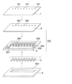
- FIG. 1 schematically shows an example of an ink jet head according to an embodiment of the present invention, disassembled for each component, and the ink jet head HD includes a first silicon substrate 1, a second silicon substrate 2, a piezoelectric element 3, and A reinforcing member 5 is provided.
- a plurality of ink discharge ports 101 are formed through the first silicon substrate 1.
- the second silicon substrate 2 is covered with the first silicon substrate 1 and bonded to form a pressure chamber groove 204 serving as a pressure chamber, an ink supply channel groove 203 serving as an ink supply path, and a common pressure chamber.
- a common pressure chamber groove 202 and an ink supply port 201 are formed.
- the first silicon substrate 1 and the second silicon substrate 2 are bonded so that the ink discharge port 101 of the first silicon substrate 1 and the pressure chamber groove 204 of the second silicon substrate 2 correspond one-to-one. Is done.
- the piezoelectric element 3 is bonded to a position corresponding to each pressure chamber 204 on the surface of the second silicon substrate 2 opposite to the surface to be bonded to the first silicon substrate 1.
- the piezoelectric element 3 is an actuator that is made of PZT (lead zirconate titanate) and ejects ink from the ink ejection port 101.
- the reinforcing member 5 is bonded to the surface of the second silicon substrate 2 opposite to the surface to which the first silicon substrate 1 is bonded.
- a chamber formed by the pressure chamber groove 204 and the first silicon substrate 1 is referred to as a pressure chamber 204, and a chamber formed by the ink supply channel groove 203 and the first silicon substrate 1 is referred to as a pressure chamber 204.
- a chamber formed by the common pressure chamber groove 202 and the first silicon substrate 1 is referred to as an ink supply path 203 and is referred to as a common pressure chamber 202.
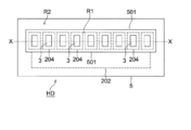
- FIG. 2 is a plan view of the inkjet head shown in FIG.
- FIG. 3 is an enlarged sectional view taken along line X in FIG.
- the reinforcing member 5, the second silicon substrate 2, and the first silicon substrate 1 are arranged in this order from the top, and the ink ejection surface 1a (lower surface) of the first silicon substrate 1 on which ink droplets are ejected. ) Is formed in a plane.
- Each pressure chamber 204 has an opening area larger than that of the ink discharge port 101 formed in the first silicon substrate 1, and from a bonding surface (pressure chamber forming surface) with the first silicon substrate 1. It is recessed at a predetermined depth.
- the piezoelectric elements 3 are individually bonded to the back side of each pressure chamber 204, that is, the side opposite to the bonding surface of the second silicon substrate 2 with the first silicon substrate 1.
- Each piezoelectric element is connected to drive pulse generating means (not shown) through electrodes (not shown) provided on both upper and lower surfaces.
- the piezoelectric element is deformed, and the bottom 25 of each pressure chamber 204 is vibrated by the electro-mechanical conversion action of this piezoelectric element 3,
- the pressure wave is generated in the ink in the pressure chamber 204 by changing the volume of the ink.
- the ink meniscus in the ink discharge port 101 vibrates and is ejected from the ink discharge port 101 to form ink droplets, which are ejected downward in the figure.
- each pressure chamber 204 functions as a diaphragm. For this reason, the depth of the recess when the pressure chamber 204 is dry-etched on the second silicon substrate 2 is adjusted so that the thickness of the bottom surface 25 of each pressure chamber 204 is preferably 1 to 20 ⁇ m. .
- the reinforcing member 5 has an opening 501 that opens a first region R ⁇ b> 1 including a region in which the pressure chambers 204 and the piezoelectric elements 3 are disposed, and a region in which partition walls separating the individual pressure chambers 204 are disposed. And is formed as a frame-shaped member that covers the second region R2 surrounding the first region R1.
- the reinforcing member 5 imparts rigidity to the second silicon substrate 2, and suppresses crosstalk by suppressing the entire second silicon substrate 2 from vibrating when the diaphragm is vibrated by the piezoelectric element 3.
- it is formed of a material having high rigidity such as aluminum, stainless steel or glass having a thickness of 200 to 500 ⁇ m, and is bonded to the lower surface of the second silicon substrate 2 using an adhesive.
- the reinforcing member 5 is molded from a plate material to a desired size by machining, and the opening 501 is also formed by machining.
- the first silicon substrate 1 is manufactured by using a silicon substrate having a thickness of about 150 ⁇ m to 500 ⁇ m as a base material, for example, using a known photolithography technique (resist coating, exposure, development), an etching technique, and the like. This is performed by a procedure of penetrating the ink discharge port 101.
- the hole diameter of the ink discharge port 101 is about ⁇ 1 ⁇ m to ⁇ 30 ⁇ m.
- the second silicon substrate 2 uses a silicon substrate having a thickness of about 150 ⁇ m to 500 ⁇ m as a base material.
- a known photolithography technique resist coating, exposure, By using development and etching techniques, etc.
- pressure chamber grooves 204 serving as a plurality of pressure chambers respectively communicating with the ink discharge ports 101 of the first silicon substrate 1 and a plurality of ink supply paths communicating with the pressure chambers are obtained.
- An ink supply path groove 203, a common pressure chamber groove 202 serving as a common pressure chamber communicating with the ink supply path, and an ink supply port 201 are formed.
- the pressure chamber groove 204 has a width of about 150 ⁇ m to 350 ⁇ m, a depth of about 50 ⁇ m to 200 ⁇ m, and an ink supply.
- the channel groove 203 has a width of about 50 ⁇ m to 150 ⁇ m, a depth of about 30 ⁇ m to 150 ⁇ m
- the common pressure chamber groove has a width of about 400 ⁇ m to 1000 ⁇ m, a depth of about 50 ⁇ m to 200 ⁇ m
- the ink supply port 201 is a through-hole with a diameter of about ⁇ 400 ⁇ m to 1500 ⁇ m. is there.
- the etching method for the silicon substrate is preferably a silicon (Si) anisotropic dry etching method capable of performing etching processing perpendicularly to the surface of the second silicon substrate.
- silicon (Si) anisotropic dry etching method Sangyo Tosho Co., Ltd. “Semiconductor dry etching technology” can be referred to.
- first silicon substrate 1 and the second silicon substrate 2 processed by the method described so far are bonded using an anodic bonding technique. This will be described below.
- FIG. 4 is a diagram showing a bonding process between the first silicon substrate 1 and the second silicon substrate 2, and FIG. 4A shows an ink discharge port (not shown) using the silicon substrate as a base material.
- the first silicon substrate 1 and the second silicon substrate 2 in which grooves such as the pressure chamber groove 204 are formed by the above-described processing.
- the first silicon substrate 1 and the second silicon substrate 2 are bonded by anodic bonding.
- silicon is used as a material constituting one of the substrates, and the other is silicon with a mobile ion, for example, a glass material containing sodium ions (Na + ).
- a material having a linear expansion coefficient relatively similar to (Si) (the linear expansion coefficient of silicon is about 4.2 ⁇ 10 ⁇ 6 / ° C.), for example, borosilicate glass is used. .
- borosilicate glass containing mobile ions hereinafter referred to as borosilicate glass
- Pyrex registered trademark
- Corning USA
- Tempax Float registered trademark
- Shot Japan Co., Ltd. have these linear expansion coefficients ⁇
- the linear expansion coefficients of Pyrex (registered trademark) and Tempax Float (registered trademark) are both about 3.2 ⁇ 10 ⁇ 6 / ° C. ⁇ Is more preferable from the viewpoint of.
- a silicon substrate is used instead of borosilicate glass as a base material. Then, a borosilicate glass film is formed on the bonding surface of the silicon substrate as the base material to form a borosilicate glass surface.
- the film thickness in this case may be a film thickness that can be strongly bonded by anodic bonding, and is 0.5 ⁇ m from the viewpoint of the density and uniformity of the film and the heating and applied voltage of the bonding surface required during anodic bonding described later.
- the range of ⁇ 3 ⁇ m is preferable, and the range of 1 ⁇ m to 2 ⁇ m is more preferable.
- the borosilicate glass film may be formed by any one of a vacuum deposition method, a radio frequency (RF) magnetron sputtering method, and an ion plating method, and the substrate temperature is easily formed at the time of film formation. It is preferable to heat so that it may become 250 degreeC or more.
- the upper limit of the temperature is not particularly defined, but is preferably about 400 ° C. from the viewpoint of a substrate mounting jig, a substrate temperature control device during film formation, and the like.
- the base materials of the first silicon substrate 1 and the second silicon substrate 2 are both silicon substrates for ease of fine processing. Therefore, one of the bonding surfaces of the first silicon substrate 1 and the second silicon substrate 2 needs to be the borosilicate glass surface described above.
- a borosilicate glass film is provided on the second silicon substrate 2 side, it is predicted that deformation due to the deposition of the film will occur in the already formed fine shape due to the film thickness that forms the surface of the borosilicate glass. Is done.
- the bottom 25 (vibration plate) of the pressure chamber 204 is thickened by this film, so that the structure of the pressure chamber 204 itself is strengthened and distortion due to the piezoelectric element 3 cannot be sufficiently generated. As a result, ink cannot be sufficiently discharged.
- the drive power of the piezoelectric element 3 must be increased.
- the surface side of the first silicon substrate 1 shown in FIG. 4B that covers the second silicon substrate is a borosilicate glass surface, and the first silicon substrate 1 is used as the substrate, and the second of the substrate is the second one.
- a relatively thick borosilicate glass thick film 110 in the range of 0.5 ⁇ m to 3 ⁇ m is provided on the surface side covering the silicon substrate.
- the polarity of the voltage applied when anodic bonding is performed is positive (+) on the silicon substrate side and negative (-) on the borosilicate glass substrate side. If it does in this way, an electric current will flow at the same time that a joining interface closely_contact
- the second silicon substrate 2 is applied with a positive (+) voltage
- the first silicon substrate 1 having the borosilicate glass thick film 110 is applied with a negative ( ⁇ ) voltage. It ’s fine.
- the high temperature state at the time of joining is in the range of 300 ° C. to 550 ° C.
- a constant temperature bath capable of maintaining such an atmospheric temperature or a simple method using a hot plate having good insulation with a built-in ceramic heater or the like. What is necessary is just to heat the junction part of the 1st silicon substrate 1 and the 2nd silicon substrate 2.
- the electric field strength of the DC voltage applied between the first silicon substrate 1 and the second silicon substrate 2 by the DC high voltage power source 4 is preferably in the range of 30 kV / mm to 200 kV / mm.
- the applied voltage range is 15 to 100 V, and if it is 3 ⁇ m, it is 90 to 600 V.
- the bonding surfaces are all anodic bonded so that no adhesive is present at all the bonding portions, the entire ink jet head is given rigidity, and the vibration plate is vibrated by the piezoelectric element 3.
- the piezoelectric element 3 is bonded to the combined body A of the first silicon substrate 1 and the second silicon substrate 2 bonded by anodic bonding as described above, and an ink jet head is completed.
- the inkjet head HD is designed so that the drive frequency and fluid resonance frequency of the inkjet head are not included in the frequency range within the half width with respect to the structural resonance frequency of the inkjet head.
- the structural resonance frequency of the inkjet head can be obtained by numerical calculation or experiment.
- a drive voltage waveform obtained by sweeping the drive frequency is input to a piezoelectric element in one pressure chamber, and ink is ejected. From the deformation amount of the head at that time, for example, the deformation amount of the ink ejection surface It can be calculated. When the drive frequency versus the deformation amount is plotted, the frequency at which the deformation amount reaches the maximum value becomes the resonance point, which is the structural resonance frequency of the inkjet head.
- analysis can be performed using general-purpose numerical analysis software, or if it can be approximated to a simple model, it can be easily calculated without using software.
- the structural resonance frequency of the inkjet head HD can be changed by adjusting the overall thickness of the inkjet head HD, the area of the opening 501 of the reinforcing member 5, and the like. For example, the structural resonance frequency is lowered because the rigidity is lowered by reducing the overall thickness or increasing the area of the opening 501 of the reinforcing member 5.
- the thickness of at least one of the first silicon substrate 1, the second silicon substrate 2, and the reinforcing member 5 may be reduced, or the reinforcing member 5 may be eliminated.
- the drive frequency of the inkjet head can be changed by adjusting the drive frequency of the piezoelectric element 3.
- the fluid resonance frequency of the inkjet head is a resonance frequency of a plurality of fluid vibration modes generated when a pressure wave is excited in ink (fluid) in the pressure chamber 204 when the piezoelectric element 3 is driven.
- One of them is the resonance frequency of the natural vibration of the pressure chamber, conventionally called Helmholtz vibration.
- the other is the resonance frequency of the natural vibration (hereinafter referred to as the meniscus natural vibration) caused by the meniscus free surface in the ink discharge port.
- a plurality of vibration modes and resonance points thereof that is, the resonance frequency f1 of the natural vibration of the meniscus in the nozzle and the resonance frequency f2 of the natural vibration of the pressure chamber can be obtained by numerical calculation or experiment.
- analysis can be performed using general-purpose numerical analysis software, or if it can be approximated to a simple model, it can be easily calculated without using software.
- L is an inertance component [kg / m 4 ]
- La is an inertance component in the piezoelectric element
- Ln is an inertance component in the ink discharge port
- Li is an inertance component in the ink supply path
- Lc is in the pressure chamber.
- R is a resistance component [N ⁇ s / m 5 ]
- Ra is a resistance component in the piezoelectric element
- Rn is a resistance component in the ink ejection port
- Ri is a resistance component in the ink supply path
- Rc is a resistance component in the pressure chamber. is there.
- C is a capacitive component [m 5 / N]
- Ca is a capacitive component in the piezoelectric element
- Cn is a capacitive component in the ink ejection port
- Ci is a capacitive component in the ink supply path
- Cc is a capacitive component in the pressure chamber.
- the inertance component L in each part is given by equation (1), where S [m 2 ] is the cross-sectional area of the flow path, l [m] is the flow path length, and ⁇ [kg / m 3 ] is the ink density. It is done.
- ⁇ is a shape factor determined by the cross-sectional shape of the flow path, and is about 1.3 when the cross-section is circular or rectangular.
- the resistance component R in each part is given by the equation (2) when the ink viscosity is ⁇ [Pa ⁇ s] and the diameter is d [m] when the flow path cross section is circular.
- Cc and Ca which are terms related to compression inside the fluid, are V [m 3 ] for the pressure chamber volume, ⁇ [kg / m 3 ] for the ink density, and c [m / s] for the sound velocity of the ink. It is given by equation (3).
- Cn which is a term related to the fluid free surface, is given by equation (4), where the surface tension ⁇ [N / m] of the ink and the diameter of the ink discharge port are d [m].
- the elements Ci, Ra, and La that have little influence on the characteristics are set to approximately zero, and the remaining elements are synthesized, so that the vibration mode is separated into two.
- the first vibration mode is mode 1, the resonance point is f1, the second vibration mode is mode 2, and the resonance point is f2.
- Vibration mode 1 is the natural vibration of the meniscus that occurs on the surface of the meniscus.
- the vibration mode 2 is a natural vibration of the pressure chamber caused by pressure fluctuation in the pressure chamber, and the meniscus is raised when this is transmitted to the ink discharge port. This is conventionally called Helmholtz vibration.
- the resonance frequency f1 of the meniscus natural vibration is expressed by the following equation (5).
- the resonance frequency f2 of the natural vibration of the pressure chamber is expressed by the following equation (6).
- the parameters governing f1 and f2 are only the inertance component and the capacitance component of each part. That is, f1 and f2 are determined by the combination of the inertance component and the capacitance component of each part.
- the resonance frequency of the fluid vibration mode of the inkjet head HD can be adjusted by adjusting the size and shape of the ink discharge port 101, the pressure chamber 204, and the ink supply path 203 of the inkjet head HD.
- the inkjet head HD is designed so that the drive frequency and fluid resonance frequency of the inkjet head are not included in the frequency range within the half width with respect to the structural resonance frequency of the inkjet head. For this reason, the drive frequency of the inkjet head and the fluid resonance frequency can be separated from the frequency region within the half width with respect to the structural resonance frequency of the inkjet head, and by suppressing the structural resonance of the inkjet head, The vibration of the head and the occurrence of crosstalk that occur during driving can be suppressed, unstable ejection states such as crosstalk are unlikely to occur, and the ejection characteristics are stabilized.
- FIG. 5 is a plan view of another example of the inkjet head HD according to the embodiment of the present invention.
- the reinforcing member 5 has an opening 501 that opens the first region R1 including the region of the common pressure chamber 202. That is, a partition wall such as a region where the pressure chamber 204 and the piezoelectric element 3 are disposed, a region where the ink supply path 203 is disposed, a region where the common pressure chamber 202 is disposed, and a partition partitioning the individual pressure chambers 204 are disposed.
- the reinforcing member 5 is formed as a frame member that has an opening 501 that opens the first region R1 including the region and covers the second region R2 that surrounds the first region R1.
- the inkjet head HD of this example is designed so that the drive frequency and fluid resonance frequency of the inkjet head are not included in the frequency range within the half-value width with respect to the structural resonance frequency of the inkjet head. For this reason, by suppressing the structural resonance of the inkjet head, it is possible to suppress the vibration of the head and the occurrence of crosstalk during driving, and it is difficult for unstable discharge states such as crosstalk to occur, and the discharge characteristics Is stabilized.
- the area where the common pressure chamber 202 is arranged is also opened.
- flow path crosstalk is generated in which the pressure wave is transmitted to the non-driven pressure chamber via the common pressure chamber 202, but the area where the common pressure chamber is disposed is opened as in this example.
- the pressure wave in the common pressure chamber can be absorbed by the vibration of the wall forming the common pressure chamber, and the flow path crosstalk can be suppressed.
- FIG. 6 is a diagram schematically showing still another example of the ink jet head HD according to the embodiment of the present invention.
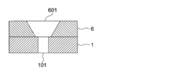
- a glass substrate 6 is provided between the first silicon substrate 1 and the second silicon substrate 2.
- the glass substrate 6 has an ink flow path hole 601 at a position corresponding to the ink discharge port 101.
- the ink flow path hole 601 has a larger diameter than the ink discharge port 101 of the first silicon substrate 1 as shown in FIG.
- the glass substrate 6 is bonded to the second silicon substrate 2 and the first silicon substrate 1 by anodic bonding. Therefore, borosilicate glass is preferable as the material of the glass substrate 6.
- the inkjet head HD of this example is designed so that the drive frequency and fluid resonance frequency of the inkjet head are not included in the frequency range within the half-value width with respect to the structural resonance frequency of the inkjet head. For this reason, by suppressing the structural resonance of the inkjet head, it is possible to suppress the vibration of the head and the occurrence of crosstalk during driving, and it is difficult for unstable discharge states such as crosstalk to occur, and the discharge characteristics Is stabilized.
- the bonding surfaces are all anodic bonded so that no adhesive is present at all the bonding portions, the entire ink jet head is given rigidity, and the vibration plate is vibrated by the piezoelectric element 3.
- ink discharge ports 101 and the pressure chambers 204 that require a high degree of miniaturization can be processed and formed on the silicon substrates 1 and 2, a fine and high-density pattern can be formed by using a semiconductor integrated circuit manufacturing technique. Is possible.
- the glass substrate 6 is simply formed with a simple through hole, and the processing operation during dry etching is extremely simple.
- FIGS. 8 and 9 show still another example of the ink jet head according to the embodiment of the present invention, in which the pressure chambers, piezoelectric elements, and ink discharge ports are arranged in two rows.
- the piezoelectric element group 3A, the piezoelectric element group 3B, and the pressure chamber groups 204A and 204B are arranged in two upper and lower rows, and although not shown, ink discharge ports corresponding to these are arranged.
- a common pressure chamber 202A corresponding to the upper pressure chamber group 204A is disposed above the pressure chamber group 204a, and a corresponding common pressure chamber 202B is disposed below the lower pressure chamber group 204B.
- the reinforcing member 5 is formed as a frame-shaped member that opens the region R1 including the pressure chamber groups 204A and 204B and the common pressure chamber groups 202A and 202B and covers the region R2 surrounding the region R1.
- the arrangement of the pressure chamber group, the piezoelectric element group, and the ink discharge port group is the same as that in FIG. 8, but the shape of the reinforcing member 5 is different from that in FIG.
- the region R11 including 3A, the lower pressure chamber group 204B, the region R12 including the piezoelectric element group 3B, the region R13 including the upper common pressure chamber 202A, and the region R14 including the lower common pressure chamber 202B are opened.
- the reinforcing member 5 is formed as a frame-like member that covers the region surrounding the region.
- a region R22 between the lower pressure chamber group 204B and a region R23 between the lower pressure chamber group 204B and the lower common pressure chamber 202B is a region covered with the reinforcing member 5.
- the inkjet head HD of this example is designed so that the drive frequency and fluid resonance frequency of the inkjet head are not included in the frequency range within the half-value width with respect to the structural resonance frequency of the inkjet head. For this reason, by suppressing the structural resonance of the inkjet head, it is possible to suppress the vibration of the head and the occurrence of crosstalk during driving, and it is difficult for unstable discharge states such as crosstalk to occur, and the discharge characteristics Is stabilized.
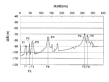
- the vertical axis in FIGS. 10 and 11 represents the speed (differential displacement value) when the amount of deformation of the head measured with a laser Doppler meter when driving one pressure chamber by sine wave input, and the horizontal axis represents the drive. Indicates the frequency.
- the numerical value of the velocity on the vertical axis corresponds to the deformation amount of the head, and the larger the numerical value, the larger the deformation amount of the head, that is, the amplitude of vibration.
- FIG. 10 shows the amount of head deformation when a reinforcing member whose thickness is adjusted is provided
- FIG. 11 shows the amount of head deformation when a reinforcing member whose thickness is not adjusted is provided.
- each symbol means the following.
- any one of the resonance frequencies (peak values) of each resonance spectrum matches or is close to the drive frequency or fluid resonance frequency of the inkjet head, structural resonance of the head occurs, which adversely affects ejection stability. Effect.
- the driving frequency of the inkjet head and the fluid resonance frequency are included in a frequency range within a half-value width with respect to the structural resonance frequency of the inkjet head. It is necessary to set not to.
- Such setting is performed, for example, by adjusting the thickness of the reinforcing member 5 in FIG. If the adjustment is made on the ink jet head main body side, the ejection characteristics may change. Therefore, it is advantageous to adjust the structural resonance frequency by the reinforcing member 5.
- fluid resonance frequencies f1 and f2 are determined for the flow path shape and ink physical properties of the head.
- the fluid resonance point of this head is that the resonance frequency f2 of the natural vibration of the pressure chamber is 98 kHz and the resonance frequency f1 of the natural vibration of the meniscus is 335 kHz, and droplets having different diameters can be formed in each mode. .
- FIG. 11 shows the case where the thickness of the reinforcing member 5 is not adjusted, and the first to sixth resonance spectra are separated from 98 kHz, which is the resonance frequency f2 of the natural vibration of the pressure chamber.
- This f2 is not included in any of the frequency regions ⁇ F1 to ⁇ F6 within the half-value widths of the first to sixth resonance spectra.
- the inkjet head is ejected at a drive frequency of less than 25 kHz, and the drive frequency is not included in the frequency region ⁇ F within the full width at half maximum with respect to all the resonance frequencies F, and the ejection stability is good. It was confirmed that.
- the driving frequency of the inkjet head and f1 or f2 were examined. Is included in the frequency region ⁇ F within the half width with respect to any of the resonance frequencies F, the ejection stability is poor, and the drive frequency of the inkjet head or f1 or f2 is within the frequency region ⁇ F within the half width with respect to all the resonance frequencies F. When it was not included, it was confirmed that the ejection stability was good.
- the drive frequency of the ink jet head or the fluid resonance frequency and the structural resonance frequency coincide with each other or interfere with each other, the ejection becomes unstable, or an unintended change occurs with respect to the change of the discharge condition.
- the interference can be prevented by designing the reinforcement in consideration of the drive frequency and resonance frequency of the inkjet head.
- the ink jet head HD suppresses the occurrence of crosstalk due to resonance of the ink jet head when ink is ejected, the ejection characteristics are stabilized.
Landscapes
- Particle Formation And Scattering Control In Inkjet Printers (AREA)
Abstract
L'invention porte sur une tête à jet d'encre qui rend possible la suppression des vibrations de tête et des interférences lorsque la tête est entraînée. La tête à jet d'encre comprend : une pluralité d'orifices d'éjection d'encre ; une pluralité de chambres de pression qui communiquent avec les orifices d'éjection d'encre ; et un élément piézoélectrique qui comprime l'encre par variation du volume de chacune des chambres de pression. La fréquence de résonance dans le fluide et la fréquence d'entraînement de la tête à jet d'encre ne sont pas comprises dans une région de fréquence dans la demi largeur de la fréquence de résonance structurale de la tête à jet d'encre.
Priority Applications (1)
| Application Number | Priority Date | Filing Date | Title |
|---|---|---|---|
| JP2011519681A JPWO2010146945A1 (ja) | 2009-06-15 | 2010-05-10 | インクジェットヘッド |
Applications Claiming Priority (2)
| Application Number | Priority Date | Filing Date | Title |
|---|---|---|---|
| JP2009-142000 | 2009-06-15 | ||
| JP2009142000 | 2009-06-15 |
Publications (1)
| Publication Number | Publication Date |
|---|---|
| WO2010146945A1 true WO2010146945A1 (fr) | 2010-12-23 |
Family
ID=43356269
Family Applications (1)
| Application Number | Title | Priority Date | Filing Date |
|---|---|---|---|
| PCT/JP2010/057863 Ceased WO2010146945A1 (fr) | 2009-06-15 | 2010-05-10 | Tête à jet d'encre |
Country Status (2)
| Country | Link |
|---|---|
| JP (1) | JPWO2010146945A1 (fr) |
| WO (1) | WO2010146945A1 (fr) |
Cited By (2)
| Publication number | Priority date | Publication date | Assignee | Title |
|---|---|---|---|---|
| JP2024509866A (ja) * | 2021-03-08 | 2024-03-05 | 株式会社リコー | プリントヘッドにおけるマニフォールドの長さ |
| KR20250103471A (ko) | 2023-12-28 | 2025-07-07 | 파나소닉 아이피 매니지먼트 가부시키가이샤 | 액체 토출 헤드 및 인쇄 장치 |
Citations (8)
| Publication number | Priority date | Publication date | Assignee | Title |
|---|---|---|---|---|
| JPH10211705A (ja) * | 1997-01-30 | 1998-08-11 | Ricoh Co Ltd | 電気機械変換素子及びその製造方法並びにインクジェットヘッド |
| WO1999065689A1 (fr) * | 1998-06-18 | 1999-12-23 | Matsushita Electric Industrial Co., Ltd. | Dispositif de projection de fluide et son procede de fabrication |
| JP2002011876A (ja) * | 2000-06-30 | 2002-01-15 | Fujitsu Ltd | インクジェットプリントヘッド及びインクジェットプリンタ |
| JP2002301816A (ja) * | 2001-01-31 | 2002-10-15 | Canon Inc | インクジェット記録装置およびインクジェットヘッドの駆動方法 |
| JP2004330514A (ja) * | 2003-05-02 | 2004-11-25 | Ricoh Co Ltd | 画像形成装置 |
| JP2005125631A (ja) * | 2003-10-24 | 2005-05-19 | Ricoh Co Ltd | 液滴吐出ヘッド及び画像形成装置 |
| JP2006095769A (ja) * | 2004-09-28 | 2006-04-13 | Fuji Photo Film Co Ltd | 液体吐出ヘッド及び画像形成装置 |
| JP2009056786A (ja) * | 2007-09-03 | 2009-03-19 | Ricoh Co Ltd | 液体吐出ヘッド及び画像形成装置 |
-
2010
- 2010-05-10 WO PCT/JP2010/057863 patent/WO2010146945A1/fr not_active Ceased
- 2010-05-10 JP JP2011519681A patent/JPWO2010146945A1/ja active Pending
Patent Citations (8)
| Publication number | Priority date | Publication date | Assignee | Title |
|---|---|---|---|---|
| JPH10211705A (ja) * | 1997-01-30 | 1998-08-11 | Ricoh Co Ltd | 電気機械変換素子及びその製造方法並びにインクジェットヘッド |
| WO1999065689A1 (fr) * | 1998-06-18 | 1999-12-23 | Matsushita Electric Industrial Co., Ltd. | Dispositif de projection de fluide et son procede de fabrication |
| JP2002011876A (ja) * | 2000-06-30 | 2002-01-15 | Fujitsu Ltd | インクジェットプリントヘッド及びインクジェットプリンタ |
| JP2002301816A (ja) * | 2001-01-31 | 2002-10-15 | Canon Inc | インクジェット記録装置およびインクジェットヘッドの駆動方法 |
| JP2004330514A (ja) * | 2003-05-02 | 2004-11-25 | Ricoh Co Ltd | 画像形成装置 |
| JP2005125631A (ja) * | 2003-10-24 | 2005-05-19 | Ricoh Co Ltd | 液滴吐出ヘッド及び画像形成装置 |
| JP2006095769A (ja) * | 2004-09-28 | 2006-04-13 | Fuji Photo Film Co Ltd | 液体吐出ヘッド及び画像形成装置 |
| JP2009056786A (ja) * | 2007-09-03 | 2009-03-19 | Ricoh Co Ltd | 液体吐出ヘッド及び画像形成装置 |
Cited By (2)
| Publication number | Priority date | Publication date | Assignee | Title |
|---|---|---|---|---|
| JP2024509866A (ja) * | 2021-03-08 | 2024-03-05 | 株式会社リコー | プリントヘッドにおけるマニフォールドの長さ |
| KR20250103471A (ko) | 2023-12-28 | 2025-07-07 | 파나소닉 아이피 매니지먼트 가부시키가이샤 | 액체 토출 헤드 및 인쇄 장치 |
Also Published As
| Publication number | Publication date |
|---|---|
| JPWO2010146945A1 (ja) | 2012-12-06 |
Similar Documents
| Publication | Publication Date | Title |
|---|---|---|
| US5736993A (en) | Enhanced performance drop-on-demand ink jet head apparatus and method | |
| US6695437B2 (en) | Inkjet recording head and method for driving an inkjet recording head | |
| US10710362B2 (en) | Droplet deposition head and method of providing adjustment data therefor | |
| EP0648606A2 (fr) | Tête à jet d'encre à la demande et méthode | |
| JP2014172295A (ja) | 液滴吐出ヘッド及び画像形成装置 | |
| JPWO2010146945A1 (ja) | インクジェットヘッド | |
| JPWO2009107552A1 (ja) | インクジェットヘッド及びその駆動方法 | |
| JP4801061B2 (ja) | 液滴堆積装置 | |
| US7503645B2 (en) | Droplet generator and ink-jet recording device using thereof | |
| CN106256535A (zh) | 配置成使用高粘度材料再填充喷嘴区域的打印头 | |
| US20060132547A1 (en) | Liquid Transporting Apparatus and Method of Manufacturing Liquid Transporting Apparatus | |
| JP2004106217A (ja) | インクジェットヘッドおよびそれを備えたインクジェット式記録装置 | |
| KR101069927B1 (ko) | 잉크젯 헤드 | |
| JP3666506B2 (ja) | インクジェット記録装置の製造方法 | |
| JP2007203610A (ja) | 液滴吐出ヘッド及び液滴吐出装置 | |
| JP2001277505A (ja) | インクジェットヘッド | |
| Mawatari et al. | Development of New Inkjet Head Applying MEMS Technology and Thin Film Actuator. | |
| JP2007182002A (ja) | インクジェットヘッドおよびその製造方法ならびにインクジェット式記録装置 | |
| JP2015062995A (ja) | インクジェットヘッドの製造方法及びインクジェットヘッド | |
| JP2008023837A (ja) | 液滴吐出装置 | |
| JP3384202B2 (ja) | インクジェット記録装置の駆動方法 | |
| JPWO2009104487A1 (ja) | インクジェットヘッド | |
| JP2008260152A (ja) | インクジェット記録ヘッド及びその作製方法 | |
| JP4935939B2 (ja) | 液滴吐出装置 | |
| JP2013212592A (ja) | インクジェットヘッド並びにその駆動方法およびプログラム |
Legal Events
| Date | Code | Title | Description |
|---|---|---|---|
| 121 | Ep: the epo has been informed by wipo that ep was designated in this application |
Ref document number: 10789322 Country of ref document: EP Kind code of ref document: A1 |
|
| WWE | Wipo information: entry into national phase |
Ref document number: 2011519681 Country of ref document: JP |
|
| NENP | Non-entry into the national phase |
Ref country code: DE |
|
| 122 | Ep: pct application non-entry in european phase |
Ref document number: 10789322 Country of ref document: EP Kind code of ref document: A1 |