WO2011001843A2 - Dispositif et procédé de travail dans des pipelines - Google Patents
Dispositif et procédé de travail dans des pipelines Download PDFInfo
- Publication number
- WO2011001843A2 WO2011001843A2 PCT/JP2010/060426 JP2010060426W WO2011001843A2 WO 2011001843 A2 WO2011001843 A2 WO 2011001843A2 JP 2010060426 W JP2010060426 W JP 2010060426W WO 2011001843 A2 WO2011001843 A2 WO 2011001843A2
- Authority
- WO
- WIPO (PCT)
- Prior art keywords
- pipe
- space
- wall
- pressure boundary
- boundary seal
- Prior art date
- Legal status (The legal status is an assumption and is not a legal conclusion. Google has not performed a legal analysis and makes no representation as to the accuracy of the status listed.)
- Ceased
Links
Images


Classifications
-
- B—PERFORMING OPERATIONS; TRANSPORTING
- B08—CLEANING
- B08B—CLEANING IN GENERAL; PREVENTION OF FOULING IN GENERAL
- B08B9/00—Cleaning hollow articles by methods or apparatus specially adapted thereto
- B08B9/02—Cleaning pipes or tubes or systems of pipes or tubes
- B08B9/027—Cleaning the internal surfaces; Removal of blockages
- B08B9/04—Cleaning the internal surfaces; Removal of blockages using cleaning devices introduced into and moved along the pipes
- B08B9/053—Cleaning the internal surfaces; Removal of blockages using cleaning devices introduced into and moved along the pipes moved along the pipes by a fluid, e.g. by fluid pressure or by suction
-
- F—MECHANICAL ENGINEERING; LIGHTING; HEATING; WEAPONS; BLASTING
- F16—ENGINEERING ELEMENTS AND UNITS; GENERAL MEASURES FOR PRODUCING AND MAINTAINING EFFECTIVE FUNCTIONING OF MACHINES OR INSTALLATIONS; THERMAL INSULATION IN GENERAL
- F16L—PIPES; JOINTS OR FITTINGS FOR PIPES; SUPPORTS FOR PIPES, CABLES OR PROTECTIVE TUBING; MEANS FOR THERMAL INSULATION IN GENERAL
- F16L55/00—Devices or appurtenances for use in, or in connection with, pipes or pipe systems
- F16L55/18—Appliances for use in repairing pipes
-
- B—PERFORMING OPERATIONS; TRANSPORTING
- B08—CLEANING
- B08B—CLEANING IN GENERAL; PREVENTION OF FOULING IN GENERAL
- B08B3/00—Cleaning by methods involving the use or presence of liquid or steam
- B08B3/02—Cleaning by the force of jets or sprays
-
- B—PERFORMING OPERATIONS; TRANSPORTING
- B08—CLEANING
- B08B—CLEANING IN GENERAL; PREVENTION OF FOULING IN GENERAL
- B08B5/00—Cleaning by methods involving the use of air flow or gas flow
- B08B5/04—Cleaning by suction, with or without auxiliary action
-
- B—PERFORMING OPERATIONS; TRANSPORTING
- B08—CLEANING
- B08B—CLEANING IN GENERAL; PREVENTION OF FOULING IN GENERAL
- B08B9/00—Cleaning hollow articles by methods or apparatus specially adapted thereto
- B08B9/02—Cleaning pipes or tubes or systems of pipes or tubes
- B08B9/027—Cleaning the internal surfaces; Removal of blockages
- B08B9/04—Cleaning the internal surfaces; Removal of blockages using cleaning devices introduced into and moved along the pipes
- B08B9/049—Cleaning the internal surfaces; Removal of blockages using cleaning devices introduced into and moved along the pipes having self-contained propelling means for moving the cleaning devices along the pipes, i.e. self-propelled
-
- B—PERFORMING OPERATIONS; TRANSPORTING
- B08—CLEANING
- B08B—CLEANING IN GENERAL; PREVENTION OF FOULING IN GENERAL
- B08B9/00—Cleaning hollow articles by methods or apparatus specially adapted thereto
- B08B9/08—Cleaning containers, e.g. tanks
- B08B9/46—Inspecting cleaned containers for cleanliness
-
- B—PERFORMING OPERATIONS; TRANSPORTING
- B25—HAND TOOLS; PORTABLE POWER-DRIVEN TOOLS; MANIPULATORS
- B25J—MANIPULATORS; CHAMBERS PROVIDED WITH MANIPULATION DEVICES
- B25J11/00—Manipulators not otherwise provided for
- B25J11/0075—Manipulators for painting or coating
-
- B—PERFORMING OPERATIONS; TRANSPORTING
- B25—HAND TOOLS; PORTABLE POWER-DRIVEN TOOLS; MANIPULATORS
- B25J—MANIPULATORS; CHAMBERS PROVIDED WITH MANIPULATION DEVICES
- B25J11/00—Manipulators not otherwise provided for
- B25J11/008—Manipulators for service tasks
- B25J11/0085—Cleaning
-
- F—MECHANICAL ENGINEERING; LIGHTING; HEATING; WEAPONS; BLASTING
- F16—ENGINEERING ELEMENTS AND UNITS; GENERAL MEASURES FOR PRODUCING AND MAINTAINING EFFECTIVE FUNCTIONING OF MACHINES OR INSTALLATIONS; THERMAL INSULATION IN GENERAL
- F16L—PIPES; JOINTS OR FITTINGS FOR PIPES; SUPPORTS FOR PIPES, CABLES OR PROTECTIVE TUBING; MEANS FOR THERMAL INSULATION IN GENERAL
- F16L55/00—Devices or appurtenances for use in, or in connection with, pipes or pipe systems
- F16L55/26—Pigs or moles, i.e. devices movable in a pipe or conduit with or without self-contained propulsion means
- F16L55/28—Constructional aspects
- F16L55/30—Constructional aspects of the propulsion means, e.g. towed by cables
- F16L55/38—Constructional aspects of the propulsion means, e.g. towed by cables driven by fluid pressure
-
- F—MECHANICAL ENGINEERING; LIGHTING; HEATING; WEAPONS; BLASTING
- F16—ENGINEERING ELEMENTS AND UNITS; GENERAL MEASURES FOR PRODUCING AND MAINTAINING EFFECTIVE FUNCTIONING OF MACHINES OR INSTALLATIONS; THERMAL INSULATION IN GENERAL
- F16L—PIPES; JOINTS OR FITTINGS FOR PIPES; SUPPORTS FOR PIPES, CABLES OR PROTECTIVE TUBING; MEANS FOR THERMAL INSULATION IN GENERAL
- F16L58/00—Protection of pipes or pipe fittings against corrosion or incrustation
- F16L58/02—Protection of pipes or pipe fittings against corrosion or incrustation by means of internal or external coatings
-
- F—MECHANICAL ENGINEERING; LIGHTING; HEATING; WEAPONS; BLASTING
- F26—DRYING
- F26B—DRYING SOLID MATERIALS OR OBJECTS BY REMOVING LIQUID THEREFROM
- F26B21/00—Arrangements for supplying or controlling air or other gases for drying solid materials or objects
- F26B21/001—Air generating units, e.g. movable or independent of drying enclosure
- F26B21/002—Air generating units, e.g. movable or independent of drying enclosure with means for indirect air heating, i.e. using heat exchangers
Definitions
- the present invention removes foreign matters such as rust and aquatic organisms adhering to the inner surface of various pipes such as water supply pipes, drainage pipes and gas pipes, for example, and after removing these, coating materials such as paints and corrosion resistant alloys
- the present invention relates to an in-pipe work apparatus and method for performing maintenance work on pipes while traveling in the pipes, such as coating.
- the “in-pipe work method and apparatus” disclosed in Japanese Patent Publication No. 2003-225626 has the following problems to be solved. That is, in the “in-pipe work method and apparatus”, In order to run the working device in the pipe, a hoisting device is arranged outside the pipe, the working device is connected to the end of the measure body wound up by the hoisting device, and the measure body is The working device is wound up by a hoisting device and pulled along the axial direction of the pipe, and thus the working device is caused to travel in the pipe.
- this “in-pipe work method and apparatus” since the step of inserting a cord-like body from one opening of the opened pipe to the other opening is essential, the length of the pipe is long.
- the process of inserting the cord-like body is complicated. Further, in the “in-pipe work method and apparatus”, a cleaning operation is performed to remove the foreign matter adhering to the inner surface of the pipe by the jet injection mechanism, and then an operation to suck and collect the removed foreign matter is performed. Next, the work of repairing by covering the inner surface of the pipe with a coating material is performed, but the "wet inner surface of the pipe is indispensable between the cleaning work process and the repair work process. The “drying step” is not described.
- the “forced drying of the inner surface of the wet pipe” is essential, but if the means for drying the inner surface of the wet pipe is “natural drying”, the wet It takes a lot of time to “naturally dry” the inner surface of the pipe, and the longer the time is required, the more the iron surface of the bent iron obtained by the cleaning operation is rusted again. Furthermore, it takes a lot of time to “naturally dry” the painted pipe inner surface. Therefore, the technical solutions of the present invention are as follows.
- the present invention there is no need to use a hoisting device as traveling drive means for traveling the working device in the pipe, that is, the “in-pipe working device and method” having a very large traveling driving force is provided. To do.
- the present invention also provides a “pipe working device and method” provided with “a means for forcibly drying a wet pipe inner surface”.
- the "work apparatus and method in piping” provided with the “means for forcedly drying the painted piping inner surface” is provided.
- an in-pipe work device that works while traveling inside the pipe;
- An annular pressure boundary seal whose free end portion contacts the inner wall of the pipe;
- the pressure boundary seal divides the space inside the pipe into two spaces, space A and space B, with the pressure boundary seal as a boundary;
- One end of the space A proximate to the pressure boundary seal is in communication with a suction pump via a hose;
- the other end of the space A away from the pressure boundary seal is in communication with the fluid surrounding the piping via a vacuum break valve that adjusts the negative pressure inside the space A;
- the space B the hose is arranged;
- the end of the space B away from the pressure boundary seal is in communication with the fluid surrounding the piping;
- An in-pipe working device is provided.
- the pressure boundary seal has a cross-sectional shape cut along a plane where the axis of the pipe is present, and a fixing portion attached to the apparatus, a direction away from the space A starting from the fixing portion, and the inner wall of the pipe
- the in-pipe working device according to claim 1, comprising at least a free end portion extending in a direction and contacting the inner wall.
- the pressure boundary seal has a cross-sectional shape cut along a plane where the axis of the pipe is present, and two fixing portions mounted on the apparatus, and a direction approaching the inner wall of the pipe from each of the two fixing portions.
- a valve that communicates the space B and the space inside the pressure boundary seal with at least an arc-shaped free end portion that extends in contact with the inner wall and that extends from the respective portions.
- the pressure boundary seal is attached to the apparatus via a spherical bearing so that the axis of the pressure boundary seal is in the vicinity of the axis of the pipe.
- the pressure boundary seal has, in a cross-sectional shape cut along a plane where the axis of the pipe is present, a fixed portion attached to the apparatus, a direction away from the space B starting from the fixed portion, and approaches the inner wall of the pipe
- the in-pipe working apparatus according to claim 6, comprising at least a free end extending in a direction and contacting the inner wall.
- the pressure boundary seal has a cross-sectional shape cut along a plane where the axis of the pipe is present, and two fixing portions mounted on the apparatus, and a direction approaching the inner wall of the pipe from each of the two fixing portions.
- a valve that communicates with the space A inside the pressure boundary seal and the space A, and is formed of at least an arcuate free end portion that extends in contact with the inner wall and that extends from the respective portions.
- the pressure boundary seal is attached to the apparatus via a spherical bearing so that the axis of the pressure boundary seal is in the vicinity of the axis of the pipe.
- the in-pipe working apparatus according to any one of claims 6 to 9, further comprising means for coating a coating material such as a paint or a corrosion-resistant alloy in order to coat the inner wall of the pipe. .
- An inner wall of the pipe which is implemented by running the pipe working device according to any one of claims 1 to 5 in a direction from the space B toward the space A, comprising means for causing a cleaning material such as water or an abrasive to collide.
- a first step of cleaning The pipe working device according to claim 6, comprising means for coating a coating material such as a paint or a corrosion-resistant alloy, and running on the inner wall of the pipe that runs in a direction from the space A toward the space B. And a second step of applying a coating.
- An in-pipe working method is provided.
- the present invention provides the following effects. That is, There is no need to use a hoisting device as traveling drive means for traveling the working device in the pipe, that is, an “in-pipe working device and method” having a very large traveling driving force is provided.
- a “pipe working device and method” provided with “a means for forcibly drying a wet pipe inner surface” is provided.
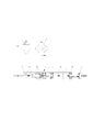
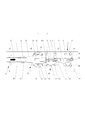
- FIG. 1 is an overall view showing a configuration of a device main body and devices attached to the device main body in the first preferred embodiment of the “pipe working device” constructed according to the present invention
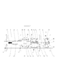
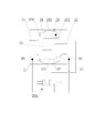
- 2 is an enlarged sectional view of the apparatus main body shown in FIG. 1
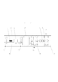
- 3 is a top view of the apparatus main body shown in FIG. 2
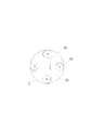
- 4 is a side view of the apparatus main body shown in FIG. 5
- a side view of the apparatus main body shown in FIG. 6 is a side view taken along the line CC of the apparatus main body shown in FIG. 2
- 7 is a side view taken along the line DD in the apparatus main body shown in FIG. 2
- FIG. 10 is a cross-sectional view showing an aspect of the curved pipe portion of the apparatus main body shown in FIG.
- the device of the first preferred embodiment of the “pipe 1 work device” constructed in accordance with the present invention is: An apparatus main body 2 disposed inside the pipe 1; A hose 5 having an upstream end connected to the apparatus body 2 and a downstream end connected to the upstream inlet of the solid / fluid separator 4; A roots-type vacuum pump 3, which is a kind of positive displacement pump, having an upstream inlet connected to a downstream outlet of the solid / fluid separator 4 and a downstream outlet opened to a space surrounding the pipe 1; ; A vacuum breaker valve 6 connected to the end on the side where the hose is not arranged at the two ends of the pipe 1; It is comprised by. Note that, at the two end portions of the pipe 1, the end portions on the side where the hose 5 is disposed are open to the space surrounding the pipe 1.
- the device body 2 is: In the first cylindrical body 21 arranged in the axial direction inside the pipe 1, there is a cylindrical cavity extending in the axial direction inside the first cylindrical body 21, and an air motor 31 with a speed reducer is provided in the cavity.
- a main rotary shaft 32 that is fixed and connected to the output shaft of the air motor 31 with a speed reducer is held by two bearings 33, and a non-oscillating wheel unit 38 is provided on the outer peripheral portion of the central portion of the first cylindrical body 21.
- the four rod non-rotating cylinders 39 are fixed, and a high-pressure tube joint 42 is attached to the right end of the outer peripheral portion of the first cylindrical body 21, and the first cylindrical body configured as described above.
- a second tubular body 22 having a shape and having a plurality of holes in a circumferential portion between the end portions;
- One end portion is flange-connected to the flange portion of the fourth cylindrical body 24, and the other end portion has a fifth cylindrical body 25 having a cylindrical shape with a reduced diameter;
- a hose joint 26 having one end connected to the fifth cylindrical body 25 via a third spherical bearing 251;
- a hose 5 connected to a hose coupling 26;
- the flange portion of the second cylindrical body 22 and the flange portion of the third cylindrical body 23 are sandwiched and fixed, and the hose 5 extends from the fixing portion 201 and approaches the inner wall of the pipe 1.
- a pressure boundary seal 20 formed of a flexible material, such as polyurethane, with a free end 202 extending and contacting the inner wall;
- a non-oscillating wheel unit 38 fixed to the outer peripheral portion of the central portion of the first cylindrical body 21;
- a high-pressure tube joint 42 is attached to the right end of the main rotating shaft 32, and between the rotating high-pressure tube joint 42 and the high-pressure tube joint 42 of the first cylindrical body 21 not rotating, that is, A main rotary shaft 32 incorporating a rotary joint mechanism 34 capable of always securing a fluid flow path between the rotating body and the non-rotating body;
- a universal joint 35 connected to the main rotary shaft 32;
- Four rod non-rotating cylinders 39 of a rocking wheel unit 37 are fixed to the outer periphery of the universal joint 35, and a nozzle 44 for injecting a cleaning material and a high-pressure tube joint 42 are provided at the right end.
- a driven rotary shaft 36 provided; A nozzle 44 for injecting a cleaning material such as water or an abrasive to clean the inner wall of the pipe 1; An oscillating wheel unit 37 fixed to the outer periphery of the driven rotary shaft 36; A high pressure tube 43 connecting the high pressure tube joint 42 of the main rotary shaft 32 and the high pressure tube joint 42 of the driven rotary shaft 36; A guide wheel unit 8 composed of three driven wheels 41 arranged on the outer periphery of the fifth cylindrical body 25; A plurality of hose guide wheel units 9 comprising three driven wheels 41 arranged on the outer periphery of the hose 5; It is composed of The pressure boundary seal 20 divides the space inside the pipe 1 into two spaces, space A: A0 and space B: B0, with the seal 20 as a boundary, and is a space communicated with the vacuum breaker valve 6. Is referred to as space A, and the space in which the hose 5 is disposed is referred to as space B.
- the oscillating wheel unit 37 The oscillating wheel unit 37; Four rod non-rotating cylinders 39 arranged radially and fixed to the outer periphery of the driven rotating shaft 36; Each of the four rod non-rotating cylinders 39 mounted on the tip of the piston rod, two each, a total of four types, that is, a total of eight driven wheels 41; Consists of: The axes of the two driven wheels 41 are not parallel to the axis of the pipe 1 but are slightly inclined.
- the four rod non-rotating cylinders 39 have a function of strongly pressing the four driven wheels 41 against the inner wall of the pipe 1, but each rod non-rotating cylinder 39 has a function to achieve its function.
- a compression coil spring may be arranged inside each cylinder case, or the rod non-rotating cylinder 39 is a rod non-rotating air cylinder, and compressed air is supplied from the outside via a rotary joint (not shown). May be.
- the structure of the non-oscillating wheel unit 38 will be described with reference to FIGS.
- the non-oscillating wheel unit 38 ;
- Four rod non-rotating cylinders 39 arranged and fixed radially on the outer periphery of the central portion of the first cylindrical body 21;
- Each of the four rod non-rotating cylinders 39 mounted on the tip of the piston rod, two each, a total of four types, that is, a total of eight driven wheels 41;
- Consists of: The axes of the two driven wheels 41 are arranged so as to be orthogonal to the axis of the pipe 1.
- the four rod non-rotating cylinders 39 have a function of strongly pressing the four driven wheels 41 against the inner wall of the pipe 1, but each rod non-rotating cylinder 39 has a function to achieve its function.
- a compression coil spring may be disposed inside each cylinder case, or the rod non-rotating cylinder 39 may be a rod non-rotating air cylinder and compressed air may be supplied from the outside.
- the vacuum breaker valve 6 includes a valve case 63 having an upstream valve hole 61 and a downstream hose joint 62, a valve plate 64 disposed inside the valve case 63, and a sliding fixed to the valve plate 64. It consists of a flexible valve rod 65 and a compression coil spring 66 for pressing the valve plate 64 firmly against the valve hole.
- FIGS. 1 to 10 The operation of the apparatus of the first preferred embodiment of the “in-pipe working apparatus” configured as described above will be described with reference to FIGS. 1 to 10.
- the air in the space A: A0 in the pipe 1 is sucked in the downstream direction, that is, in the direction of the roots type vacuum pump 3, and the space A: A0 is set pressure of the vacuum breaker valve 6 (assuming ⁇ 200 mmHg) The pressure is reduced to.
- the space A: A0 is depressurized, the air in the space B: B0 flows into the space A: A0 through the gap between the inner wall of the pipe 1 and the pressure boundary seal 20 in FIG.
- the black arrows in the figure indicate the direction in which air flows.
- the pressure in the space B: B0 where the end is opened is close to atmospheric pressure, whereas the pressure in the space A: A0 is ⁇ 200 mmHg, so the free end 202 of the pressure boundary seal 20 is Due to the pressure difference between the space A: A0 and the space B: B0, it is strongly pressed against the inner wall of the pipe 1, and therefore the gap between the inner wall of the pipe 1 and the pressure boundary seal 20 is even smaller. become.
- the gap between the inner wall of the pipe 1 and the pressure boundary seal 20 the actual inner wall of the pipe 1 has irregularities corroded by rust and the like, and the surface of the pressure boundary seal 20 has fine scratches.
- a high-speed air flow flows from the space B: B0 to the space A: A0 through a slight gap caused by the unevenness and scratches.
- the vacuum breaker valve 6 of FIG. 8 when the pressure in the space A: A0 becomes ⁇ 200 mmHg or less, the atmospheric pressure overcomes the force of the compression coil spring 66 and pushes the valve plate 64 open, so that the atmosphere enters the vacuum breaker valve 6.
- the pressure in the space A: A0 is maintained at -200 mmHg. Note that due to the pressure difference (200 mmHg) between the space A: A0 and the space B: B0, the apparatus main body 2 receives a strong force acting from the space B: B0 to the space A: A0.
- the non-oscillating wheel unit 38 is counteracted to rotate counterclockwise, but the axis of the driven wheel 41 attached to the non-oscillating wheel unit 38 is a plane orthogonal to the axis of the pipe 1. Since it is above, the driven wheel 41 does not rotate, and thus the non-oscillating wheel unit 38 is prevented from rotating counterclockwise. That is, when the air motor 31 with a speed reducer is rotationally driven in the clockwise direction in the state viewed from left to right in FIG. 2, the apparatus main body 2 travels in the direction of the white arrow.
- the travel driving force of the device main body 2 toward the white arrow direction is caused by the pressure difference (200 mmHg) between the space A: A0 and the space B: B0 in addition to the travel drive force of the rocking wheel unit 37. Since the force that pushes the main body 2 in the direction of the white arrow is added, the total traveling driving force becomes very large.
- the high pressure water is supplied to the high pressure tube joint 42 attached to the first cylindrical body 21, the high pressure water is supplied to the rotary joint mechanism 34, the high pressure tube joint 42 attached to the main rotating shaft 32, and the high pressure tube. 43, transferred through the high-pressure tube joint 42 attached to the driven rotating shaft 36, and jetted vigorously from the nozzle 44 toward the inner wall of the pipe 1, and foreign matter such as rust adhering to the inner wall is peeled off and cleaned. .
- FIG. 10 is a cross-sectional view showing an aspect of the curved pipe portion of the apparatus main body 2 shown in FIG. 2, but the pressure boundary seal 20 is attached to the apparatus main body 2 via a spherical bearing. Even if there is a portion, the axis of the pressure boundary seal 20 is always in the vicinity of the axis of the pipe 1.
- FIG. 11 is an overall view showing the configuration of the apparatus main body 2 and the devices attached to the apparatus main body 2 in the apparatus of the second preferred embodiment of the “in-pipe work apparatus” configured according to the present invention
- 12 is an enlarged sectional view of the apparatus main body 2 shown in FIG. 11
- 13 is an enlarged cross-sectional view of the pressure relief valve 7 shown in FIG. 11
- FIG. 14 is an enlarged cross-sectional view of the pressure boundary seal portion in the apparatus main body 2 shown in FIG.
- the other aspects are the same except for the arrangement of the pressure boundary seal 20. Is omitted.
- the apparatus of the second preferred embodiment of the “in-pipe working apparatus” constructed in accordance with the present invention is; An apparatus main body 2 disposed inside the pipe 1; A hose 5 whose downstream end is connected to the apparatus body 2 and whose upstream end is connected to the outlet of the roots pump 3; Roots type pump 3 which is a kind of positive displacement pump; Pressure relief valves 7 connected to the ends of the pipe 1 at two ends where the hose 5 is not disposed; It is comprised by. Note that, at the two end portions of the pipe 1, the end portions on the side where the hose 5 is disposed are open to the space surrounding the pipe 1.
- the device body 2 is: In the first cylindrical body 21 arranged in the axial direction in the pipe 1, there is a cylindrical cavity extending in the axial direction inside the first cylindrical body 21, and an air motor 31 with a speed reducer is fixed in the cavity.
- the main rotating shaft 32 connected to the output shaft of the air motor 31 with a speed reducer is held by two bearings 33, and the non-oscillating wheel unit 38 is disposed on the outer peripheral portion of the center portion of the first cylindrical body 21.
- Four rod non-rotating cylinders 39 are fixed, and a high-pressure tube joint 42 is attached to the right end of the outer peripheral portion of the first cylindrical body 21, and the first cylindrical body 21 configured as described above.
- a second tubular body 22 having a shape and having a plurality of holes in a circumferential portion between the end portions;
- One end portion is flange-connected to the flange portion of the fourth cylindrical body 24, and the other end portion has a fifth cylindrical body 25 having a cylindrical shape with a reduced diameter;
- a hose joint 26 having one end connected to the fifth cylindrical body 25 via a third spherical bearing 251;
- a hose 5 connected to a hose coupling 26;
- the flange portion of the fourth cylindrical body 24 and the flange portion of the fifth cylindrical body 25 are sandwiched and fixed, and the direction opposite to the direction in which the hose 5 extends from the fixing portion 201 and the inner wall of the pipe 1 is fixed.
- a pressure boundary seal 20 formed of a flexible material, such as polyurethane, with a free end 202 extending in the approaching direction and contacting the inner wall;
- a non-oscillating wheel unit 38 fixed to the outer peripheral portion of the central portion of the first cylindrical body 21;
- a high-pressure tube joint 42 is attached to the right end of the main rotating shaft 32, and between the rotating high-pressure tube joint 42 and the high-pressure tube joint 42 of the first cylindrical body 21 not rotating, That is, the main rotary shaft 32 incorporating the rotary joint mechanism 34 capable of always ensuring a fluid flow path between the rotating body and the non-rotating body;
- a universal joint 35 connected to the main rotary shaft 32;
- Four rod non-rotating cylinders 39 of the oscillating wheel unit 37 are fixed to the outer periphery of the universal joint 35, and a nozzle 44 for injecting a coating material and a high-pressure tube joint 42 are provided at the right end.
- a driven rotary shaft 36 provided; A nozzle 44 for spraying a coating material such as a paint or a corrosion resistant alloy to coat the inner wall of the pipe 1; An oscillating wheel unit 37 fixed to the outer periphery of the driven rotary shaft 36; A high pressure tube 43 connecting the high pressure tube joint 42 of the main rotary shaft 32 and the high pressure tube joint 42 of the driven rotary shaft 36; A guide wheel unit 8 composed of three driven wheels 41 arranged on the outer periphery of the fifth cylindrical body 25; A plurality of hose guide wheel units 9 comprising three driven wheels 41 arranged on the outer periphery of the hose 5; It is composed of The pressure boundary seal 20 divides the space inside the pipe 1 into two spaces of space A: A0 and space B: B0 with the seal 20 as a boundary, and is a space communicated with the pressure relief valve 7. Is referred to as space A, and the space in which the hose 5 is disposed is referred to as space B.
- the oscillating wheel unit 37 The oscillating wheel unit 37; Four rod non-rotating cylinders 39 arranged radially and fixed to the outer periphery of the driven rotating shaft 36; Each of the four rod non-rotating cylinders 39 mounted on the tip of the piston rod, two each, a total of four types, that is, a total of eight driven wheels 41; Consists of: The axes of the two driven wheels 41 are not parallel to the axis of the pipe 1 but are slightly inclined.
- the four rod non-rotating cylinders 39 have a function of strongly pressing the four driven wheels 41 against the inner wall of the pipe 1, but each rod non-rotating cylinder 39 has a function to achieve its function.
- a compression coil spring may be arranged inside each cylinder case, or the rod non-rotating cylinder 39 is a rod non-rotating air cylinder, and compressed air is supplied from the outside via a rotary joint (not shown). May be.
- the structure of the non-oscillating wheel unit 38 will be described with reference to FIGS.
- the non-oscillating wheel unit 38 ;
- Four rod non-rotating cylinders 39 arranged and fixed radially on the outer periphery of the central portion of the first cylindrical body 21;
- Each of the four rod non-rotating cylinders 39 mounted on the tip of the piston rod, two each, a total of four types, that is, a total of eight driven wheels 41;
- Consists of: The axes of the two driven wheels 41 are arranged so as to be orthogonal to the axis of the pipe 1.
- the four rod non-rotating cylinders 39 have a function of strongly pressing the four driven wheels 41 against the inner wall of the pipe 1, but each rod non-rotating cylinder 39 has a function to achieve its function.
- a compression coil spring may be disposed inside each cylinder case, or the rod non-rotating cylinder 39 may be a rod non-rotating air cylinder, and compressed air may be supplied from the outside.
- the pressure relief valve 7 includes a valve case 73 having a downstream valve hole 71 and an upstream hose joint 72, a valve plate 74 disposed outside the valve case 73, and a sliding fixed to the valve plate 74. It consists of a flexible valve rod 75 and a compression coil spring 76 for pressing the valve plate 74 firmly against the valve hole 71.
- the pressure in the space B: B0 where the end is open is close to atmospheric pressure, whereas the pressure in the space A: A0 is 200 mmHg. Due to the pressure difference between A: A0 and space B: B0, it is strongly pressed against the inner wall of the pipe 1, so that the gap between the inner wall of the pipe 1 and the pressure boundary seal 20 is even smaller. Become. As for the gap between the inner wall of the pipe 1 and the pressure boundary seal 20, the actual inner wall of the pipe 1 has irregularities corroded by rust and the like, and the surface of the pressure boundary seal 20 has fine scratches. A high-speed air flow flows from the space A: A0 to the space B: B0 through a slight gap due to the unevenness and scratches of the surface. In the pressure relief valve 7 of FIG.
- the non-oscillating wheel unit 38 is counteracted to rotate clockwise, but the axis of the driven wheel 41 attached to the non-oscillating wheel unit 38 is on a plane orthogonal to the axis of the pipe 1. Therefore, the driven wheel 41 does not rotate, and the rotation of the non-oscillating wheel unit 38 in the clockwise direction is prevented. That is, when the air motor 31 with a speed reducer is driven to rotate counterclockwise in the state viewed from left to right in FIG. 12, the apparatus main body 2 travels in the direction of the white arrow.
- the travel driving force of the device main body 2 toward the white arrow direction is caused by the pressure difference (200 mmHg) between the space A: A0 and the space B: B0 in addition to the travel drive force of the rocking wheel unit 37. Since the force that pushes the main body 2 in the direction of the white arrow is added, the total traveling driving force becomes very large.
- the paint is supplied to the high-pressure tube joint 42 attached to the first cylindrical body 21, the paint is applied to the rotary joint mechanism 34, the high-pressure tube joint 42 attached to the main rotary shaft 32, the high-pressure tube 43, It is transferred via a high-pressure tube joint 42 attached to the driven rotary shaft 36, sprayed from the nozzle 44 toward the inner wall of the pipe 1, and the inner wall is painted.
- the high-speed airflow flows from space A: A0 to space B: B0 through a slight gap between the inner wall of the pipe 1 and the pressure boundary seal 20, the inner wall of the pipe 1 is wet.
- forced drying is performed by the action of a high-speed and high-temperature air flow.
- the coating dries quickly due to the action of a high-speed and high-temperature air flow from the roots type pump 3 to the pressure relief valve 7 via the hose 5, space B: B0, space A: A0.
- the pump As a characteristic of a discharge pump that discharges air, the pump has a function of compressing air, and heat is generated when the air is compressed. Therefore, the air discharged from the pump is hot air. Thus, hot air is sent to the space A: A0.
- the apparatus of the first preferred embodiment of the “in-pipe working device” configured according to the present invention described above cleans the inner wall of the pipe 1 by causing a cleaning material such as water or an abrasive to collide with it. It can be conveniently used in the first step.
- the apparatus of the second preferred embodiment of the “in-pipe working apparatus” constructed according to the present invention is advantageous in the second step of coating the inner wall of the pipe 1 with a coating material such as paint or corrosion-resistant alloy. Can be used. Therefore, it is very convenient if the apparatus main body of the first preferred embodiment and the apparatus main body of the second preferred embodiment are the same apparatus. The difference between the apparatus main body of the first preferred embodiment and the apparatus main body of the second preferred embodiment will be described.
- the pressure boundary seal starts from its fixed part, and extends in the “direction in which the hose extends” and in the direction approaching the inner wall of the pipe, and contacts the inner wall.
- the pressure boundary seal starts from its fixed portion and extends in the “opposite direction of the direction in which the hose extends” and in the direction of approaching the inner wall of the pipe to contact the inner wall. It has a free end. That is, the only difference is whether the free end of the pressure boundary seal extends in the “direction in which the hose extends” or “in the direction opposite to the direction in which the hose extends”.
- the apparatus main body of the first preferred embodiment and the apparatus main body of the second preferred embodiment are configured in accordance with the present invention as means for achieving the object of having the same shape.
- the apparatus of the third preferred embodiment of the “pipe working apparatus” and the apparatus of the fourth preferred embodiment are also proposed below.
- FIG. 15 is an enlarged cross-sectional view showing another embodiment of the pressure boundary seal portion shown in FIGS. 9 and 14. It should be noted that in the difference between the apparatus main body of the first to second preferred embodiments and the apparatus main body of the third preferred embodiment, the other aspects are the same except for the pressure boundary seal, so the drawings are related. Omitted.
- the pressure boundary seal 20 has a cross-sectional shape cut along a plane where the axis of the pipe 1 exists, and the pipe 1 is connected to each of the two fixing parts 201 and the two fixing parts 201 attached to the apparatus.
- a space 203 and a space B inside the pressure boundary seal are constituted by at least an arcuate free end 202 extending in a direction approaching the inner wall, contacting the inner wall, and a portion extending from each of the inner walls. : B0, or a three-port two-position single solenoid valve 204 for selectively communicating the space 203 inside the pressure boundary seal with the space A: A0.
- the three-port two-position single solenoid valve 204 communicates the space 203 inside the pressure boundary seal with the space B: B0 in the device configuration of the first preferred embodiment, and the device configuration of the second preferred embodiment. At times, the space 203 inside the pressure boundary seal and the space A: A0 are communicated.
- the space 203 inside the pressure boundary seal and the space B: B0 are communicated with each other to configure the device configuration of the second preferred embodiment.
- this means may be used.
- FIG. 16 is a partially enlarged sectional view showing another embodiment of the apparatus main body shown in FIGS. 1 and 11;
- FIG. 17 is a side view of the apparatus main body shown in FIG.
- the apparatus main body of the fourth preferred embodiment includes two pressure boundary seals unlike the apparatus main bodies of the first to third preferred embodiments.
- the non-oscillating wheel unit is: Four rod non-rotating cylinders 39 arranged and fixed radially on the outer periphery of the central portion of the first cylindrical body 21; Each of the four rod non-rotating cylinders 39 mounted on the tip of the piston rod, two each, a total of four types, ie a total of eight driven wheels 41; Consists of: The axes of the two driven wheels 41 are arranged so as to be orthogonal to the axis of the pipe 1.
- the four rod non-rotating cylinders 39 have a function of strongly pressing the four driven wheels 41 against the inner wall of the pipe 1, but each rod non-rotating cylinder 39 has a function to achieve its function.
- a compression coil spring may be disposed inside each cylinder case, or the rod non-rotating cylinder 39 may be a rod non-rotating air cylinder, and compressed air may be supplied from the outside.
- the apparatus body of the fourth preferred embodiment includes the following two pressure boundary seals. That is, The flange portion of the second cylindrical body 22 and the flange portion of the third cylindrical body 23 are sandwiched and fixed, and the hose 5 extends from the fixing portion 201 and approaches the inner wall of the pipe 1.
- a pressure boundary seal 20A formed from a flexible material, such as polyurethane, with a free end 202 extending and contacting the inner wall;
- the flange portion of the fourth cylindrical body 24 and the flange portion of the fifth cylindrical body 25 are sandwiched and fixed, and the direction opposite to the direction in which the hose 5 extends from the fixing portion 201 and the inner wall of the pipe 1 is fixed.
- a pressure boundary seal 20B formed of a flexible material such as polyurethane, with a free end 202 extending in the approaching direction and contacting the inner wall.
- the pressure boundary seal 20A is used in the apparatus configuration of the first preferred embodiment.
- the free end portion 202 is strongly pressed against the inner wall of the pipe 1 due to the pressure difference between the space A: A0 and the space B: B0, and has a sealing function.
- the apparatus configuration of the second preferred embodiment In some cases, the free end 202 is not strongly pressed against the inner wall of the pipe 1 and therefore does not have a sealing function.
- the pressure boundary seal 20B does not have a sealing function because the free end portion 202 is not strongly pressed against the inner wall of the pipe 1, and the second preferred embodiment.
- the free end 202 is strongly pressed against the inner wall of the pipe 1 due to the pressure difference between the space A: A0 and the space B: B0 and has a sealing function.
- the device body is provided with a swinging wheel unit and a non-swinging wheel unit as means for causing the device body to run inside the pipe. .
- the rocking wheel unit is: A plurality of rod non-rotating cylinders arranged radially on the outer periphery of a rotating shaft that is driven to rotate; each of the rod non-rotating cylinders is mounted, and its axis is slightly inclined from the axis of the pipe A driven wheel arranged; means for supplying a pressurized fluid to the non-rotating cylinder of the rod for pressing the driven wheel against the inner wall of the pipe by the non-rotating cylinder of the rod; or A compression coil spring disposed inside a rod non-rotating cylinder;
- the non-oscillating wheel unit is also: A plurality of rod non-rotating cylinders arranged radially on the outer periphery of the non-rotating shaft; and a follower mounted on each of the rod non-rotating cylinders, the axis of which is on a plane perpendicular to the axis of the pipe A means for supplying a pressurized fluid to the non-rotating cylinder, or a non
- Means for causing the apparatus main body to travel inside the pipe is not limited to the means described above.
- a wire rope is connected to the apparatus main body, and the apparatus main body is pulled by the wire rope. Also good.
- the apparatus and the pipe are described as being in the atmosphere, but the apparatus of the present invention is applied even when the apparatus and the pipe are in water. Is something that can be done.
- the present invention removes foreign matters such as rust and aquatic organisms adhering to the inner surface of various pipes such as water supply pipes, drainage pipes and gas pipes, for example, and after removing these, coating materials such as paints and corrosion resistant alloys It can be conveniently used as an in-pipe work apparatus and method for performing maintenance work on the pipe while traveling in the pipe, such as coating.
- FIG. 1 is an overall view showing a configuration of a device main body and devices attached to the device main body in a device according to a first preferred embodiment of a “pipe working device” configured according to the present invention.
- the expanded sectional view of the apparatus main body shown in FIG. FIG. 3 is a top view of the apparatus main body shown in FIG. 2.
- FIG. 3 is a side view of the device main body shown in FIG.
- FIG. 3 is a side view taken along the line BB in the apparatus main body shown in FIG. 2.
- FIG. 3 is a side view taken along the line CC in the apparatus main body shown in FIG. 2.
- FIG. 3 is a side view of the apparatus main body shown in FIG.
- the expanded sectional view of the vacuum breaker valve shown in FIG. FIG. 3 is an enlarged cross-sectional view of a pressure boundary seal portion in the apparatus main body shown in FIG. 2.
- Sectional drawing which shows the aspect in the curved pipe part of the apparatus main body shown in FIG. FIG. 5 is an overall view showing the configuration of an apparatus main body and apparatuses attached to the apparatus main body in the apparatus of the second preferred embodiment of the “in-pipe working apparatus” configured according to the present invention.
- the expanded sectional view of the pressure relief valve shown in FIG. FIG. 13 is an enlarged cross-sectional view of a pressure boundary seal portion in the apparatus main body shown in FIG. 12.
- the expanded sectional view which shows another embodiment of the pressure boundary seal part shown in FIG. 9 and FIG. FIG. 12 is a partially enlarged cross-sectional view showing another embodiment of the apparatus main body shown in FIGS. 1 and 11.
- FIG. 17 is a side view taken along the line BB in the apparatus main body shown
Landscapes
- Engineering & Computer Science (AREA)
- Mechanical Engineering (AREA)
- General Engineering & Computer Science (AREA)
- Chemical & Material Sciences (AREA)
- Combustion & Propulsion (AREA)
- Physics & Mathematics (AREA)
- Fluid Mechanics (AREA)
- Robotics (AREA)
- Cleaning In General (AREA)
- Spray Control Apparatus (AREA)
- Coating Apparatus (AREA)
- Manipulator (AREA)
- Drying Of Solid Materials (AREA)
- Cleaning By Liquid Or Steam (AREA)
Abstract
Priority Applications (3)
| Application Number | Priority Date | Filing Date | Title |
|---|---|---|---|
| US13/380,091 US20120090111A1 (en) | 2009-06-28 | 2010-06-21 | Working device for an internal pipe and working method for the same |
| EP10794013.2A EP2450113A4 (fr) | 2009-06-28 | 2010-06-21 | Dispositif et procédé de travail dans des pipelines |
| CN2010800395769A CN102574171A (zh) | 2009-06-28 | 2010-06-21 | 配管内作业装置及方法 |
Applications Claiming Priority (2)
| Application Number | Priority Date | Filing Date | Title |
|---|---|---|---|
| JP2009-153079 | 2009-06-28 | ||
| JP2009153079A JP5521407B2 (ja) | 2009-06-28 | 2009-06-28 | 配管内作業装置および方法 |
Publications (2)
| Publication Number | Publication Date |
|---|---|
| WO2011001843A2 true WO2011001843A2 (fr) | 2011-01-06 |
| WO2011001843A3 WO2011001843A3 (fr) | 2011-03-24 |
Family
ID=43411535
Family Applications (1)
| Application Number | Title | Priority Date | Filing Date |
|---|---|---|---|
| PCT/JP2010/060426 Ceased WO2011001843A2 (fr) | 2009-06-28 | 2010-06-21 | Dispositif et procédé de travail dans des pipelines |
Country Status (6)
| Country | Link |
|---|---|
| US (1) | US20120090111A1 (fr) |
| EP (1) | EP2450113A4 (fr) |
| JP (1) | JP5521407B2 (fr) |
| KR (2) | KR101003754B1 (fr) |
| CN (1) | CN102574171A (fr) |
| WO (1) | WO2011001843A2 (fr) |
Cited By (2)
| Publication number | Priority date | Publication date | Assignee | Title |
|---|---|---|---|---|
| JP2014018702A (ja) * | 2012-07-12 | 2014-02-03 | Urakami Kk | 管内を移動し且つ作業を行う装置 |
| US20230278058A1 (en) * | 2015-12-22 | 2023-09-07 | Trinity Bay Worx, Llc | Multi-axis articulating and rotary spray system and method |
Families Citing this family (42)
| Publication number | Priority date | Publication date | Assignee | Title |
|---|---|---|---|---|
| JP2012223678A (ja) * | 2011-04-16 | 2012-11-15 | Urakami Kk | フレキシブル球状物体または該フレキシブル球状物体を具備した管内移動体 |
| KR101362544B1 (ko) | 2012-03-19 | 2014-02-13 | 원영식 | 엘보우 및 그 엘보우를 포함하는 배기장치 |
| CN103316873B (zh) * | 2013-07-11 | 2014-12-31 | 淮安市淮安区南闸农机修配厂 | 旋转式管道清洗器 |
| CN103480616B (zh) * | 2013-09-24 | 2015-12-23 | 北京航天益森风洞工程技术有限公司 | 波纹管清洗装置 |
| KR101670072B1 (ko) * | 2014-04-14 | 2016-10-27 | 주식회사 지앤지테크놀러지 | 강변 여과수 수평집수용 관정 청소용 고압방사기를 포함하는 청소장비의 이동 장치 및 이를 이용한 관정 청소 방법 |
| KR101433063B1 (ko) | 2014-06-11 | 2014-08-25 | 김인영 | 포신 자동청소기 |
| CN104668246A (zh) * | 2015-02-04 | 2015-06-03 | 淮安市白湖电子科技有限公司 | 管道冲刮疏通器 |
| CN104607341B (zh) * | 2015-02-15 | 2016-11-02 | 辽宁工程技术大学 | 一种牵引式管道变径自适应防腐喷涂装备 |
| KR101732506B1 (ko) | 2015-07-24 | 2017-05-04 | 삼성중공업 주식회사 | 배관 건조 장치 |
| CN105234052A (zh) * | 2015-10-29 | 2016-01-13 | 中国石油集团渤海石油装备制造有限公司 | 一种大口径弯管内涂层涂覆设备 |
| FR3052533B1 (fr) | 2016-06-13 | 2018-11-16 | Battakarst | Cloche de projection de grenaille et d'aspiration de la grenaille projetee, robot pour la renovation de conduites forcees, muni d'une telle cloche |
| CN105964636B (zh) * | 2016-07-16 | 2018-07-27 | 嵊州亿源投资管理有限公司 | 一种汽油管道内壁清洗烘干智能一体机 |
| CN106238419B (zh) * | 2016-07-16 | 2019-02-26 | 辽宁联海石油化工工程有限公司 | 一种石油管道内壁清洗烘干处理机 |
| KR101924571B1 (ko) * | 2016-11-10 | 2019-02-27 | 삼성중공업 주식회사 | 배관 내부 검사용 로봇 |
| KR102016324B1 (ko) | 2017-11-06 | 2019-08-30 | 삼성중공업 주식회사 | 배관 내벽 세척장치 |
| CN107855859A (zh) * | 2017-11-06 | 2018-03-30 | 中广核工程有限公司 | 核电站管道焊缝内壁打磨机器人 |
| KR102016314B1 (ko) | 2018-01-23 | 2019-08-30 | 삼성중공업 주식회사 | 배관 세척장치 |
| KR102079166B1 (ko) * | 2018-03-26 | 2020-04-08 | 수자원기술 주식회사 | 관로 내부를 이동하면서 관로 내부 표면처리 및 세정과 동시에 처리물질을 실시간으로 배출하는 원뿔대 형상의 셕션스크레이퍼를 구비한 처리 물질 배출시스템 및 이를 이용한 세정물질 배출 방법 |
| KR20200084676A (ko) | 2019-01-03 | 2020-07-13 | (주)디앤엠코리아 | 임플란트의 어버트먼트 |
| CN109973751B (zh) * | 2019-05-05 | 2023-12-19 | 裴嘉阳 | 管道修补器 |
| CN110385095A (zh) * | 2019-07-15 | 2019-10-29 | 刘彦杰 | 一种用于石墨烯生产的密封性能好的密闭反应装置 |
| CN112547714B (zh) * | 2019-09-25 | 2024-11-15 | 厦门佰欧环境智能科技有限公司 | 管道清理系统及方法 |
| CN110813953B (zh) * | 2019-12-16 | 2024-08-16 | 中国工程物理研究院激光聚变研究中心 | 一种高压喷淋清洗机 |
| KR102212017B1 (ko) * | 2020-09-02 | 2021-02-05 | 수자원기술 주식회사 | 진공 파괴 수단을 구비한 관로 시공 부산물 배출 시스템 |
| CN112452604B (zh) * | 2020-11-09 | 2021-12-28 | 胡艳梅 | 一种城市地下管道修复装置 |
| CN112959226A (zh) * | 2021-03-10 | 2021-06-15 | 湖南机电职业技术学院 | 一种管道抛光机器人 |
| CN113085130B (zh) * | 2021-04-07 | 2022-08-26 | 深圳市旭辉发光通讯科技有限公司 | 一种光纤制造外护套挤塑成型加工设备及成型加工方法 |
| CN113182105B (zh) * | 2021-04-12 | 2022-12-30 | 湖南省浏阳市官渡建筑工程有限公司 | 一种建筑钢管脚手架内壁铁锈去除油漆喷涂装置 |
| CN113389974B (zh) * | 2021-05-26 | 2022-11-15 | 中建安装集团有限公司 | 一种用于建筑施工管理的新型管道检测装置 |
| CN113309929B (zh) * | 2021-05-28 | 2022-03-15 | 燕山大学 | 一种仿生气囊式无动力移动管道机器人及控制方法 |
| CN113515068A (zh) * | 2021-06-17 | 2021-10-19 | 中广核研究院有限公司 | 多功能管道作业机器人控制系统 |
| CN113601525B (zh) * | 2021-08-06 | 2023-06-02 | 上海工程技术大学 | 面向风电塔筒牺牲阳极块焊接的环形轨道轮式行走机器人 |
| CN114293954B (zh) * | 2021-12-06 | 2023-10-13 | 中国矿业大学 | 一种煤层气管清洗设备 |
| CN114182192B (zh) * | 2021-12-21 | 2023-10-13 | 中国人民解放军陆军装甲兵学院 | 一种用于管道内壁具有自行移动功能的高速电弧加工装置 |
| CN114472377B (zh) * | 2022-01-17 | 2023-04-07 | 德州职业技术学院(德州市技师学院) | 一种管道清洁用超声波除尘设备 |
| CN115121558B (zh) * | 2022-07-18 | 2023-07-21 | 国网河南省电力公司博爱县供电公司 | 一种电力管道泥土类障碍物定点冲洗机器人 |
| CN115283160B (zh) * | 2022-09-30 | 2022-12-13 | 江苏捷达离心机制造有限公司 | 一种离心机制造用喷涂装置 |
| CN116748243B (zh) * | 2023-08-23 | 2023-10-20 | 潍坊德瑞克石化有限公司 | 一种石油输送管道内壁清洁装置 |
| CN117181504B (zh) * | 2023-08-28 | 2025-03-14 | 常州市安佳涂装设备有限公司 | 一种油漆喷涂设备 |
| KR102697762B1 (ko) * | 2023-10-31 | 2024-08-22 | 유일강관(주) | 강관 내부의 도장 방법 및 장치 |
| CN119588545B (zh) * | 2025-02-10 | 2025-05-06 | 靖江市联众喷涂有限公司 | 一种金属管件的防腐喷涂装置 |
| CN120079535B (zh) * | 2025-04-30 | 2025-08-26 | 兰州交通大学 | 一种盐渍土环境下混凝土防腐设备 |
Citations (1)
| Publication number | Priority date | Publication date | Assignee | Title |
|---|---|---|---|---|
| JP2003225626A (ja) | 2002-02-04 | 2003-08-12 | Toshiba Corp | 配管内作業方法および装置 |
Family Cites Families (15)
| Publication number | Priority date | Publication date | Assignee | Title |
|---|---|---|---|---|
| US4095378A (en) * | 1975-12-18 | 1978-06-20 | Uragami Fukashi | Device capable of suction-adhering to a wall surface and moving therealong |
| JPS60156579A (ja) * | 1984-01-27 | 1985-08-16 | Kawasaki Steel Corp | 鋼管内面塗装機 |
| US4763376A (en) * | 1986-05-27 | 1988-08-16 | Pene-Tech, Inc. | Maintenance inspection submersible transport apparatus |
| JPS6388090A (ja) * | 1987-09-11 | 1988-04-19 | 株式会社ハッコー | 既設管の管継手部清掃装置 |
| FR2678021B1 (fr) * | 1991-06-21 | 1999-01-15 | Inst Francais Du Petrole | Appareil et installation pour le nettoyage de drains, notamment dans un puits de production petroliere. |
| JP2774414B2 (ja) | 1992-05-14 | 1998-07-09 | 中部電力株式会社 | 管内流体中を走行する走行台車の走行装置 |
| DE4237352A1 (de) * | 1992-11-05 | 1994-05-11 | Hydac Technology Gmbh | Rohrreinigungsgerät |
| JPH06262152A (ja) * | 1993-03-12 | 1994-09-20 | Kitsuto:Kk | 管洗浄装置 |
| JP2000061419A (ja) * | 1998-08-25 | 2000-02-29 | Nippon Telegr & Teleph Corp <Ntt> | 既設管路のクリーニング装置 |
| US6374838B1 (en) * | 2000-02-01 | 2002-04-23 | Benton F. Baugh | Collapsible pig |
| NO312689B1 (no) * | 2000-09-05 | 2002-06-17 | Bjoern Dybdahl | Fremgangsmåte og anordning for brönntesting |
| GB2371818B (en) * | 2001-02-06 | 2004-09-22 | Ruff Pup Ltd | A casing scraper |
| JP2003039034A (ja) * | 2001-07-30 | 2003-02-12 | Yutaka Kiko Kk | 管路内清掃方法 |
| JP2004136218A (ja) | 2002-10-18 | 2004-05-13 | Meeshikku:Kk | 管路内清掃方法 |
| JP2004298794A (ja) * | 2003-03-31 | 2004-10-28 | Kumagai Gumi Co Ltd | 配管内の清掃方法及び配管内沈降硬化物の斫り装置 |
-
2009
- 2009-06-28 JP JP2009153079A patent/JP5521407B2/ja not_active Expired - Fee Related
- 2009-08-21 KR KR1020090077454A patent/KR101003754B1/ko not_active Expired - Fee Related
-
2010
- 2010-06-21 KR KR1020127002131A patent/KR20120093142A/ko not_active Withdrawn
- 2010-06-21 WO PCT/JP2010/060426 patent/WO2011001843A2/fr not_active Ceased
- 2010-06-21 CN CN2010800395769A patent/CN102574171A/zh active Pending
- 2010-06-21 EP EP10794013.2A patent/EP2450113A4/fr not_active Withdrawn
- 2010-06-21 US US13/380,091 patent/US20120090111A1/en not_active Abandoned
Patent Citations (1)
| Publication number | Priority date | Publication date | Assignee | Title |
|---|---|---|---|---|
| JP2003225626A (ja) | 2002-02-04 | 2003-08-12 | Toshiba Corp | 配管内作業方法および装置 |
Cited By (4)
| Publication number | Priority date | Publication date | Assignee | Title |
|---|---|---|---|---|
| JP2014018702A (ja) * | 2012-07-12 | 2014-02-03 | Urakami Kk | 管内を移動し且つ作業を行う装置 |
| WO2014010535A3 (fr) * | 2012-07-12 | 2014-03-13 | ウラカミ合同会社 | Dispositif destiné à se déplacer à l'intérieur d'un tuyau et à réaliser une tâche |
| US20230278058A1 (en) * | 2015-12-22 | 2023-09-07 | Trinity Bay Worx, Llc | Multi-axis articulating and rotary spray system and method |
| US12343747B2 (en) * | 2015-12-22 | 2025-07-01 | Trinity Bay Worx, Llc | Multi-axis articulating and rotary spray system and method |
Also Published As
| Publication number | Publication date |
|---|---|
| US20120090111A1 (en) | 2012-04-19 |
| CN102574171A (zh) | 2012-07-11 |
| JP5521407B2 (ja) | 2014-06-11 |
| EP2450113A4 (fr) | 2014-08-13 |
| KR20120093142A (ko) | 2012-08-22 |
| KR101003754B1 (ko) | 2010-12-23 |
| WO2011001843A3 (fr) | 2011-03-24 |
| EP2450113A2 (fr) | 2012-05-09 |
| JP2011005451A (ja) | 2011-01-13 |
Similar Documents
| Publication | Publication Date | Title |
|---|---|---|
| JP5521407B2 (ja) | 配管内作業装置および方法 | |
| JP5526310B2 (ja) | 配管内作業装置および方法 | |
| JP6511621B2 (ja) | 管内タービンブラストシステム | |
| KR100927341B1 (ko) | 노후관로의 스케일 제거장치 | |
| US11213868B2 (en) | Working device capable of moving inside pipe | |
| CN100579674C (zh) | 工业管道内壁清洗或防腐涂覆方法及装置 | |
| JP5707556B2 (ja) | 管内面封止用セルフシール式フレキシブルシールまたは該シールを具備した管内移動体 | |
| CN207057203U (zh) | 一种压力驱动、脉冲式管道冲洗刷 | |
| JP6967182B2 (ja) | 流れのある管内を走行し且つ該流れから動力を得るタービンクローラ | |
| CN117357980A (zh) | 一种可旋转的多分支反吹喷嘴 | |
| KR101000323B1 (ko) | 비굴착 배관 보수방법 | |
| CN101869900B (zh) | 转筒清壁器 | |
| CN213855162U (zh) | 一种间隙密封配合迷宫密封的清井用旋转体 | |
| CN110260091A (zh) | 一种城市地下管道旋喷修补设备 | |
| JP2014004583A (ja) | 配管内作業装置および方法 | |
| CN220725357U (zh) | 一种顺流式管道清淤装置 | |
| CN220927335U (zh) | 一种纸机湿部用真空辊 | |
| CN217191394U (zh) | 小口径风道清洗机器人 | |
| CN221907854U (zh) | 一种金属管表面防腐蚀处理装置 | |
| KR102746112B1 (ko) | 관로 세척과 진공 흡입장치 및 그 공법 | |
| CN210921454U (zh) | 火化机引射风机清灰装置 | |
| CN2275911Y (zh) | 地下管道内除垢装置 | |
| CN209315758U (zh) | 一种高压洗地器转子 | |
| CN205504262U (zh) | 一种高压油管清洗快接工具 | |
| CN117085991A (zh) | 一种新型水压传动装置 |
Legal Events
| Date | Code | Title | Description |
|---|---|---|---|
| WWE | Wipo information: entry into national phase |
Ref document number: 201080039576.9 Country of ref document: CN |
|
| 121 | Ep: the epo has been informed by wipo that ep was designated in this application |
Ref document number: 10794013 Country of ref document: EP Kind code of ref document: A2 |
|
| WWE | Wipo information: entry into national phase |
Ref document number: 13380091 Country of ref document: US |
|
| NENP | Non-entry into the national phase |
Ref country code: DE |
|
| ENP | Entry into the national phase |
Ref document number: 20127002131 Country of ref document: KR Kind code of ref document: A |
|
| WWE | Wipo information: entry into national phase |
Ref document number: 2010794013 Country of ref document: EP |