WO2011052435A1 - 原子力施設の建屋の基礎版および基礎版の建造方法 - Google Patents
原子力施設の建屋の基礎版および基礎版の建造方法 Download PDFInfo
- Publication number
- WO2011052435A1 WO2011052435A1 PCT/JP2010/068402 JP2010068402W WO2011052435A1 WO 2011052435 A1 WO2011052435 A1 WO 2011052435A1 JP 2010068402 W JP2010068402 W JP 2010068402W WO 2011052435 A1 WO2011052435 A1 WO 2011052435A1
- Authority
- WO
- WIPO (PCT)
- Prior art keywords
- steel plate
- building
- foundation
- nuclear facility
- formwork
- Prior art date
- Legal status (The legal status is an assumption and is not a legal conclusion. Google has not performed a legal analysis and makes no representation as to the accuracy of the status listed.)
- Ceased
Links
Images


Classifications
-
- E—FIXED CONSTRUCTIONS
- E04—BUILDING
- E04H—BUILDINGS OR LIKE STRUCTURES FOR PARTICULAR PURPOSES; SWIMMING OR SPLASH BATHS OR POOLS; MASTS; FENCING; TENTS OR CANOPIES, IN GENERAL
- E04H5/00—Buildings or groups of buildings for industrial or agricultural purposes
- E04H5/02—Buildings or groups of buildings for industrial purposes, e.g. for power-plants or factories
-
- G—PHYSICS
- G21—NUCLEAR PHYSICS; NUCLEAR ENGINEERING
- G21C—NUCLEAR REACTORS
- G21C13/00—Pressure vessels; Containment vessels; Containment in general
-
- G—PHYSICS
- G21—NUCLEAR PHYSICS; NUCLEAR ENGINEERING
- G21C—NUCLEAR REACTORS
- G21C13/00—Pressure vessels; Containment vessels; Containment in general
- G21C13/02—Details
- G21C13/024—Supporting constructions for pressure vessels or containment vessels
-
- Y—GENERAL TAGGING OF NEW TECHNOLOGICAL DEVELOPMENTS; GENERAL TAGGING OF CROSS-SECTIONAL TECHNOLOGIES SPANNING OVER SEVERAL SECTIONS OF THE IPC; TECHNICAL SUBJECTS COVERED BY FORMER USPC CROSS-REFERENCE ART COLLECTIONS [XRACs] AND DIGESTS
- Y02—TECHNOLOGIES OR APPLICATIONS FOR MITIGATION OR ADAPTATION AGAINST CLIMATE CHANGE
- Y02E—REDUCTION OF GREENHOUSE GAS [GHG] EMISSIONS, RELATED TO ENERGY GENERATION, TRANSMISSION OR DISTRIBUTION
- Y02E30/00—Energy generation of nuclear origin
- Y02E30/30—Nuclear fission reactors
Definitions
- the present invention relates to a basic version of a building of a nuclear facility that becomes a foundation of the building of the nuclear facility such as a reactor containment vessel and a method for constructing the basic version.
- a basic structure of a structure including a lower basic version constructed on the ground and an upper basic version constructed on the upper side of the lower basic version via a seismic isolation device is known.
- the upper foundation slab is constructed by placing concrete in a steel plate form consisting of a bottom steel plate and a side steel plate.
- the basic structure of the structure can omit assembly and dismantling work like a concrete formwork, so that it is possible to greatly reduce labor and to shorten the construction period.
- the upper foundation slab is provided with a top rebar (rebar) in a steel plate form to obtain a predetermined strength, and then concrete is cast.
- rebar top rebar
- the work of incorporating the upper end bars in the steel plate formwork is a cumbersome task, requiring a lot of manpower, so it is difficult to further shorten the construction period, and the basic structure is also complicated.
- Become In particular, when the conventional foundation structure is applied to the basic version of the building of the nuclear facility, the basic version of the building of the nuclear facility is huge. There is a risk of inviting.
- the present invention has an object to provide a foundation version of a building of a nuclear facility and a method for constructing the foundation version, which can shorten the construction period and can have a simple structure while ensuring a predetermined strength. To do.
- the basic version of the building of the nuclear facility of the present invention comprises a lower basic version provided on the ground, and an upper basic version provided above the lower basic version via a seismic isolation device, the upper basic version is It has a bottomed steel plate formwork, a hull structure part disposed in the steel plate formwork, and a concrete part filled in the steel plate formwork.
- the upper base plate can be configured such that the upper and lower bars are eliminated. Therefore, since it is not necessary to perform the rebar assembling work which becomes a complicated construction work at the time of construction of the upper basic version, the construction period can be shortened.
- the hull structure portion is at least one of a transverse reinforcing rib extending at the bottom of the steel plate mold and a longitudinal reinforcing rib extending perpendicular to the transverse reinforcing rib at the bottom of the steel plate mold. It is preferable to have one.
- the upper base plate can be configured firmly.
- the steel plate form is formed by combining a plurality of partial steel plate forms.
- the steel plate formwork when the steel plate formwork is large, the steel plate formwork can be configured by carrying in and installing the plurality of partial steel plate forms and then combining the plurality of partial steel plate forms. For this reason, even if a steel plate formwork is huge, a steel plate formwork can be installed suitably by combining a plurality of partial steel plate forms.
- the upper base plate is provided with a fitting groove formed along the base end portion of the building of the nuclear facility to be installed, and the upper base plate is fitted with the base end portion of the building in the fitting groove. It is preferable that it is comprised.
- the nuclear facility can have a strong structure.
- the upper basic version is provided with a building of a nuclear facility, and the building is a reactor containment vessel composed of a wall body having a hull structure.
- the reactor containment vessel has a ship hull structure, so that the structure of the reactor containment vessel can be strengthened.
- the basic version and the reactor containment vessel it is possible to make the construction method common and the parts to be used common.
- a method for constructing a foundation plate of a nuclear facility building according to the present invention includes a lower foundation plate and an upper foundation plate provided above the lower foundation plate via a seismic isolation device.
- Steel plate mold that installs a bottomed steel formwork with a hull structure inside on the installed frame, and a frame installation process for installing the frame on the constructed lower foundation plate It is characterized by comprising a frame installation step and a concrete filling step for filling concrete into the steel plate mold.
- the hull structure provided inside the steel plate formwork is provided with a fitting groove formed along the base end of the building, and after the steel plate formwork installation process, the base of the building is placed in the fitting groove. It is preferable to further include a building fitting process for fitting the end portion.
- the nuclear facility can have a strong structure.
- the hull structure portion having a simple structure can be provided in the steel plate formwork, the configuration in which the upper and lower bars are eliminated.
- the construction period can be shortened while ensuring a predetermined strength.
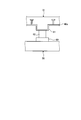
- FIG. 1 is a schematic cross-sectional view of a nuclear facility to which a basic version according to the present embodiment is applied.
- FIG. 2 is a partial schematic cross-sectional view of a nuclear facility to which the basic version according to the present embodiment is applied.
- FIG. 3 is a schematic top view of the upper base plate.
- FIG. 4 is an explanatory view showing a pedestal installation process in the foundation plate construction method according to the present embodiment.
- FIG. 5 is an explanatory view showing a steel plate form installation step in the foundation plate construction method according to the present embodiment.
- FIG. 6 is an explanatory view showing a containment container fitting step in the foundation plate construction method according to the present embodiment.
- FIG. 7 is an explanatory diagram showing a concrete filling process in the foundation plate construction method according to this embodiment.
- FIG. 8 is a schematic diagram showing a steel plate mold formed of a plurality of partial steel plate molds.
- FIG. 9 is a schematic diagram showing a steel plate mold formed by a plurality of divided steel plate molds.
- FIG. 10 is a schematic diagram showing the periphery of the seismic isolation device.
- the basic version according to this embodiment is the foundation of the building of the nuclear facility, and has a structure equipped with a seismic isolation device.
- the building of the nuclear facility for example, there are a nuclear reactor containment vessel, a nuclear fuel reprocessing facility, and the like.
- the nuclear reactor containment vessel is applied as the building of the nuclear facility.
- the nuclear facility will be explained prior to the basic version.
- the nuclear facility 1 includes a basic version 5 provided on the ground 7 and a reactor containment vessel 6 provided on the basic version 5.
- the nuclear reactor containment vessel 6 is configured to be able to store the nuclear reactor therein, and for example, a pressurized water nuclear reactor is used as the nuclear reactor.
- the reactor containment vessel 6 is composed of a wall body 10 having a hull structure portion 22, and includes a cylindrical portion 15 installed on the foundation plate 5 and a dome portion 16 disposed on the cylindrical portion 15. It is constructed integrally.
- the cylindrical portion 15 is formed in a cylindrical shape, is formed straight from the base plate 5 side toward the dome portion 16 side, and the dome portion 16 is formed in a hollow hemispherical shape.
- the wall 10 of the reactor containment vessel 6 that is, the wall 10 of the cylindrical portion 15 and the dome portion 16. Is placed between the liner plate 20 as the inner wall surface, the outer wall steel plate 21 as the outer wall surface, the hull structure 22 attached to the inner wall side of the outer wall steel plate 21, and the liner plate 20 and the outer wall steel plate 21. And a concrete part 23 made.
- the liner plate 20 is made of a steel plate and holds the reactor containment vessel 6 in an airtight manner.
- a plurality of liner anchors 25 arranged in a matrix are attached to the outer wall side of the liner plate 20.
- the plurality of liner anchors 25 can suitably fix the liner plate 20 to the concrete portion 23 without causing the liner plate 20 to peel off from the concrete portion 23.
- the outer wall steel plate 21 is made of a steel plate similarly to the liner plate 20, and a hull structure portion 22 is attached to the inner wall side of the outer wall steel plate 21 by welding.
- the hull structure 22 includes a plurality of horizontal reinforcing ribs 26 (see FIG. 1) arranged to extend in the horizontal direction and a plurality of vertical reinforcing ribs 27 arranged to extend in the vertical direction. (See FIG. 3). And each horizontal reinforcement rib 26 and each vertical reinforcement rib 27 are comprised using the T-shaped steel formed in the cross-section T shape.
- the concrete portion 23 is formed by filling concrete between the liner plate 20 and the outer wall steel plate 21.
- the basic version 5 disposed on the ground 7 will be described with reference to FIGS. 1 to 3.
- the basic version 5 is, for example, a large one having a length in the horizontal direction and a length in the vertical direction of 80 to 120 m, and is configured so that the above-described reactor containment vessel 6 can be installed.
- the base plate 5 includes a lower base plate 30 disposed on the ground 7, an upper base plate 31 disposed above the lower base plate 30 in the vertical direction, a lower base plate 30, and an upper base plate. And a seismic isolation device 32 interposed therebetween.
- the lower foundation plate 30 has a reinforced concrete structure (RC structure) in which the concrete formwork is filled with concrete after the lower end and upper end reinforcements are incorporated into the concrete formwork. It is configured.
- RC structure reinforced concrete structure
- the upper foundation plate 31 has a steel plate concrete structure (SC structure) configured by filling the steel plate mold 40 with concrete, and is formed in a rectangular shape.
- SC structure steel plate concrete structure
- the upper foundation plate 31 includes a steel plate mold 40 made of a steel plate, a hull structure portion 41 attached in the steel plate mold 40, and a concrete portion 46 filled in the steel plate mold 40. , Is composed of.
- the steel plate mold 40 is formed in a box shape with a bottom by a rectangular bottom steel plate 40a and side steel plates 40b provided on four sides of the bottom steel plate 40a.
- the hull structure portion 41 includes a plurality of transverse reinforcing ribs 42 extending on the bottom steel plate 40 a of the steel plate mold 40, and the steel plate mold 40 so as to be orthogonal to the transverse reinforcing ribs 42.
- a plurality of longitudinal reinforcing ribs 43 extending on the bottom steel plate 40a are formed in a lattice shape.
- Each transverse reinforcing rib 42 and each longitudinal reinforcing rib 43 are configured using T-shaped steel having a T-shaped cross section (see FIG. 5).
- the hull structure portion 41 is formed with a fitting groove 45 into which the proximal end portion of the reactor containment vessel 6 installed in the upper base plate 31 can be fitted.
- the fitting groove 45 has an annular shape so as to divide each transverse reinforcing rib 42 and each longitudinal reinforcing rib 43 of the hull structure portion 41 along the cylindrical shape of the proximal end portion of the reactor containment vessel 6. Is formed.
- the proximal end portion of the reactor containment vessel 6 fitted in the fitting groove 45 of the hull structure portion 41, that is, the proximal end portion of the liner plate 20 and the proximal end portion of the outer wall steel plate 21. Is in contact with the bottom steel plate 40a of the steel plate mold 40, and each of the contact portions is joined by welding.
- the concrete part 46 is formed by filling the steel plate form 40 with concrete.
- the height of the concrete portion 46 inside the reactor containment vessel 6 is configured to be lower than the height of the concrete portion 46 outside the reactor containment vessel 6.
- a bottom liner plate 50 is disposed on the upper surface of the concrete portion 46 inside the reactor containment vessel 6, and the bottom liner plate 50 is joined to the liner plate 20 of the reactor containment vessel 6 by welding.
- the inside of the reactor containment vessel 6 is covered with the liner plate 20 and the bottom liner plate 50, so that the reactor containment vessel 6 is kept airtight.
- a grout 51 serving as a floor surface in the reactor containment vessel 6 is formed by placing concrete, and the height of the grout 51 is outside the reactor containment vessel 6.
- the seismic isolation device 32 has a well-known configuration, and includes a lower protrusion 60 provided on the upper surface of the lower foundation plate 30, an upper protrusion 61 provided on the lower surface of the upper foundation plate 31, a lower protrusion 60, and an upper portion. And a seismic isolation part 62 provided between the protrusions 61.
- the lower protrusion 60 is made of columnar concrete, and is formed by placing concrete on the lower foundation plate 30.
- the upper protrusion 61 is made of a columnar steel material and is joined to the lower surface of the steel plate mold 40 by welding.
- the seismic isolation portion 62 has a multilayer structure in which disc-shaped rubber materials and disc-shaped steel plates are alternately laminated, one end of which is fixed to the upper surface of the lower projection 60 and the other end of the upper projection 61. It is fixedly disposed on the lower surface.
- the base plate 5 is free from vibration from the lower base plate 30 when the ground 7 vibrates due to an earthquake or the like.
- the seismic device 32 can suppress the vibration of the upper base plate 31.
- the construction method of the foundation plate 5 includes a lower foundation plate construction process, a gantry installation process, a steel plate form installation process, a containment container fitting process, a concrete filling process, a bottom liner arranging process, and a grout arranging process. And a seismic isolation device disposing step and a gantry removing step.
- a concrete formwork is installed on the ground 7, the upper and lower bars are incorporated into the formwork, and then filled with concrete, so that the lower part is placed on the ground 7.
- Build the base version 30 As shown in FIG. 4, in the gantry installation step, a plurality of gantry 70 is installed on the lower base plate 30 after construction.
- the steel plate mold 40 with the hull structure portion 41 attached therein is installed on the mount 70. Since the basic version 5 of the reactor containment vessel 6 is large as described above, as shown in FIG. 9, the steel plate mold 40 is divided into a plurality of divided steel plate molds 81, and is loaded and installed. After that, the steel plate mold 40 may be configured by joining the divided steel plate mold 81 divided into a plurality by welding through the bonding material 82. In this case, it is preferable that the plurality of transverse reinforcing ribs 42 and the plurality of longitudinal reinforcing ribs 43 of the hull structure portion 41 are installed on the steel plate mold 40 after joining and attached to the steel plate mold 40 by welding. At this time, in order to form an annular fitting groove 45 in the hull structure portion 41, each transverse reinforcing rib 42 and each longitudinal reinforcing rib 43 are attached to avoid the base end portion of the reactor containment vessel 6 to be installed.
- the steel plate mold 40 is divided into a plurality of divided steel plate mold
- the base end portion of the reactor containment vessel 6 is fitted into the fitting groove 45 formed in the hull structure portion 41, and the bottom steel plate 40 a of the steel plate mold 40 and After contacting the base end portion of the reactor containment vessel 6, the contact portions are joined together by welding.
- the bottom liner plate 50 is placed on the upper surface of the concrete portion 46 inside the hardened reactor containment vessel 6.
- the liner plate 20 and the bottom liner plate 50 of the reactor containment vessel 6 are joined by welding.
- concrete is placed on the disposed bottom liner plate 50 to form a grout 51 serving as a floor.
- the seismic isolation device arranging step after the steel plate mold 40 is installed, the lower projection 60 is arranged on the upper surface of the lower base plate 30 and the upper projection 61 is arranged on the lower surface of the steel plate mold 40. Thereafter, the seismic isolation portion 62 is disposed between the lower protrusion 60 and the upper protrusion 61.
- the gantry removing process after the installation of the seismic isolation device 32 is completed and the concrete filled in the steel plate mold 40 is hardened, the gantry 70 installed on the lower foundation plate 30 is removed.
- the upper foundation plate 31 can be set as the structure which abbreviate
- the upper foundation plate 31 can be configured firmly.
- the base end portion of the reactor containment vessel 6 can be fitted into the upper foundation plate 31, the upper foundation plate 31 and the reactor containment vessel 6 can be integrated, and the nuclear facility 1 has a strong structure. can do.
- the hull structure portions 22 and 41 are provided in the upper foundation plate 31 and the reactor containment vessel 6, respectively, it is possible to share a common construction method and common parts, thereby suppressing the construction cost of the nuclear facility 1. It becomes possible.
- the bottom steel plate 40a is provided with the upper projection 61 of the seismic isolation device 32.
- the present invention is not limited to this, and as shown in FIG. 10, a projecting portion that projects downward is formed on the bottom steel plate 40a.
- a structure corresponding to the upper protrusion 61 of the seismic isolation device 32 may be formed.
- the seismic isolation device 32 may be configured such that the upper protrusion 61 is eliminated and the seismic isolation 62 is disposed between the bottom steel plate 40 a and the lower protrusion 60.
- the wall 10 of the reactor containment vessel 6 has a hull structure, but the present invention is not limited to this, and a reactor containment vessel having a reinforced concrete structure (RC structure) made of reinforcing steel and concrete may be adopted. good.
- RC structure reinforced concrete structure
- a steel plate mold 40 is constituted by a plurality of partial steel plate molds 80,
- the partial steel plate formwork 80 may be joined.
- each partial steel plate formwork 80 is formed into a bottomed box shape with a bottom steel plate 80a and side steel plates 80b provided on the four sides of the bottom steel plate 80a, and a hull structure portion 41 is formed therein. Is attached.
- the steel plate mold 40 is constituted.
- the basic version of the building of the nuclear facility and the method of building the basic version according to the present invention are useful for the basic version that is the foundation of the reactor containment vessel. Suitable for simple configuration.
Landscapes
- Engineering & Computer Science (AREA)
- Physics & Mathematics (AREA)
- Plasma & Fusion (AREA)
- General Engineering & Computer Science (AREA)
- High Energy & Nuclear Physics (AREA)
- Architecture (AREA)
- Civil Engineering (AREA)
- Structural Engineering (AREA)
- Foundations (AREA)
- Buildings Adapted To Withstand Abnormal External Influences (AREA)
Abstract
Description
5 基礎版
6 原子炉格納容器
7 地盤
10 壁体
15 円筒部
16 ドーム部
20 ライナプレート
21 外壁鋼板
22 原子炉格納容器の船殻構造部
23 原子炉格納容器のコンクリート部
25 ライナ用アンカー
26 水平補強リブ
27 鉛直補強リブ
30 下部基礎版
31 上部基礎版
32 免震装置
40 鋼板型枠
40a 底部鋼板
40b 側部鋼板
41 上部基礎版の船殻構造部
42 横断補強リブ
43 縦断補強リブ
45 嵌合溝
46 上部基礎版のコンクリート部
50 底部ライナプレート
51 グラウト
60 下部突起部
61 上部突起部
62 免震部
70 架台
80 部分鋼板型枠
80a 部分鋼板型枠の底部鋼板
80b 部分鋼板型枠の側部鋼板
81 分割鋼板型枠
82 接合材
Claims (7)
- 地盤上に設けられた下部基礎版と、
免震装置を介して前記下部基礎版の上方に設けられた上部基礎版と、を備え、
前記上部基礎版は、有底の鋼板型枠と、前記鋼板型枠内に配設された船殻構造部と、前記鋼板型枠内に充填されたコンクリート部と、を有していることを特徴とする原子力施設の建屋の基礎版。 - 前記船殻構造部は、前記鋼板型枠の底部に延設された横断補強リブ、および前記鋼板型枠の底部に前記横断補強リブに直交して延設された縦断補強リブのうち、少なくともいずれか一方を有していることを特徴とする請求項1に記載の原子力施設の建屋の基礎版。
- 前記鋼板型枠は、複数の部分鋼板型枠を結合して構成されていることを特徴とする請求項1または2に記載の原子力施設の建屋の基礎版。
- 前記上部基礎版には、設置される原子力施設の建屋の基端部に沿って形成された嵌合溝が設けられ、
前記上部基礎版は、前記建屋の基端部を前記嵌合溝に嵌め込んで構成されることを特徴とする請求項1ないし3のいずれか1項に記載の原子力施設の建屋の基礎版。 - 前記上部基礎版には、原子力施設の建屋が配設され、
前記建屋は、船殻構造部を有する壁体で構成された原子炉格納容器であることを特徴とする請求項1ないし4のいずれか1項に記載の原子力施設の建屋の基礎版。 - 下部基礎版と、免震装置を介して前記下部基礎版の上方に設けられた上部基礎版と、を備え、原子力施設の建屋の土台となる基礎版の建造方法において、
建造した前記下部基礎版に架台を設置する架台設置工程と、
設置した前記架台上に、内部に船殻構造部が設けられた有底の鋼板型枠を設置する鋼板型枠設置工程と、
前記鋼板型枠内にコンクリートを充填するコンクリート充填工程と、を備えたことを特徴とする原子力施設の建屋の基礎版の建造方法。 - 前記鋼板型枠内部に設けられた前記船殻構造部には、前記建屋の基端部に沿って形成された嵌合溝が設けられ、
前記鋼板型枠設置工程後、前記嵌合溝に前記建屋の基端部を嵌め込む建屋嵌め込み工程を、さらに備えたことを特徴とする請求項6に記載の原子力施設の建屋の基礎版の建造方法。
Priority Applications (4)
| Application Number | Priority Date | Filing Date | Title |
|---|---|---|---|
| KR1020127001016A KR101381519B1 (ko) | 2009-10-30 | 2010-10-19 | 원자력 시설 건물의 기초판 및 기초판의 건조 방법 |
| US13/383,770 US8402713B2 (en) | 2009-10-30 | 2010-10-19 | Foundation for building in nuclear facilities and method for building foundation |
| CN2010800325802A CN102473465A (zh) | 2009-10-30 | 2010-10-19 | 原子能设施建筑物的混凝土基础和混凝土基础的建造方法 |
| EP10826567.9A EP2444976A4 (en) | 2009-10-30 | 2010-10-19 | FOUNDATION FOR BUILDINGS IN CORE POWER STATIONS AND METHODS FOR BUILDING THIS FUNDAMENT |
Applications Claiming Priority (2)
| Application Number | Priority Date | Filing Date | Title |
|---|---|---|---|
| JP2009251163A JP5713552B2 (ja) | 2009-10-30 | 2009-10-30 | 原子力施設の建屋の基礎版および基礎版の建造方法 |
| JP2009-251163 | 2009-10-30 |
Publications (1)
| Publication Number | Publication Date |
|---|---|
| WO2011052435A1 true WO2011052435A1 (ja) | 2011-05-05 |
Family
ID=43921859
Family Applications (1)
| Application Number | Title | Priority Date | Filing Date |
|---|---|---|---|
| PCT/JP2010/068402 Ceased WO2011052435A1 (ja) | 2009-10-30 | 2010-10-19 | 原子力施設の建屋の基礎版および基礎版の建造方法 |
Country Status (6)
| Country | Link |
|---|---|
| US (1) | US8402713B2 (ja) |
| EP (1) | EP2444976A4 (ja) |
| JP (1) | JP5713552B2 (ja) |
| KR (1) | KR101381519B1 (ja) |
| CN (1) | CN102473465A (ja) |
| WO (1) | WO2011052435A1 (ja) |
Families Citing this family (5)
| Publication number | Priority date | Publication date | Assignee | Title |
|---|---|---|---|---|
| JP5627245B2 (ja) * | 2010-02-09 | 2014-11-19 | 三菱重工業株式会社 | 原子力施設の建屋の基礎版および原子力施設 |
| JP5804889B2 (ja) * | 2011-10-20 | 2015-11-04 | 三菱重工業株式会社 | 原子炉格納容器の基礎構造 |
| CN105070338B (zh) * | 2015-07-16 | 2018-05-01 | 青岛理工大学 | 一种gfrp筋增强牺牲混凝土及其制备方法 |
| RU2753764C1 (ru) * | 2021-01-25 | 2021-08-23 | Федеральное государственное бюджетное образовательное учреждение высшего образования Северо-Кавказский горно-металлургический институт государственный технологический университет) | Реакторное отделение АЭС повышенной сейсмостойкости |
| CN113389217B (zh) * | 2021-02-10 | 2022-09-20 | 国机集团科学技术研究院有限公司 | 精密曝光、涂布装备防微振基座设计方法 |
Citations (4)
| Publication number | Priority date | Publication date | Assignee | Title |
|---|---|---|---|---|
| JPH0741494U (ja) * | 1993-12-28 | 1995-07-21 | 石川島播磨重工業株式会社 | 原子炉格納容器 |
| JPH07294682A (ja) * | 1994-04-26 | 1995-11-10 | Toshiba Corp | 原子炉格納容器 |
| JPH0980183A (ja) * | 1995-09-08 | 1997-03-28 | Ishikawajima Harima Heavy Ind Co Ltd | 原子炉格納容器 |
| JP2000265479A (ja) | 1999-03-16 | 2000-09-26 | Kajima Corp | 構造物の基礎構造 |
Family Cites Families (13)
| Publication number | Priority date | Publication date | Assignee | Title |
|---|---|---|---|---|
| GB217840A (en) * | 1923-11-22 | 1924-06-26 | Maschf Augsburg Nuernberg Ag | Improvements in and relating to foundations of gasometers |
| US3599589A (en) * | 1967-12-29 | 1971-08-17 | Mc Donnell Douglas Corp | Earthquake-resistant nuclear reactor station |
| JPS6114338A (ja) * | 1984-06-27 | 1986-01-22 | 株式会社日立製作所 | 構造体の振動減衰装置 |
| JPH0211013A (ja) * | 1988-06-29 | 1990-01-16 | Toko Inc | 表面弾性波多重モードフィルタ |
| JPH04270992A (ja) * | 1991-02-27 | 1992-09-28 | Toshiba Corp | 免震高速増殖炉 |
| JP2504360B2 (ja) | 1992-07-08 | 1996-06-05 | 鹿島建設株式会社 | 原子炉建屋 |
| JPH0659071A (ja) * | 1992-08-12 | 1994-03-04 | Kajima Corp | 原子力発電所建屋の構築工法 |
| JP3309290B2 (ja) * | 1993-05-26 | 2002-07-29 | 清水建設株式会社 | 鋼板コンクリート原子炉格納容器 |
| JPH0741494A (ja) | 1993-07-29 | 1995-02-10 | Yuki Gosei Kogyo Co Ltd | デオキシリボ核酸の固定化方法 |
| JP2003193618A (ja) * | 2001-12-25 | 2003-07-09 | Sumitomo Metal Steel Products Inc | 構造用パネルと壁体及び床体構造 |
| JP2004316100A (ja) | 2003-04-11 | 2004-11-11 | Shimizu Corp | 建物の構築方法 |
| FI123045B (fi) * | 2007-05-04 | 2012-10-15 | Pelti Kiinni Oy | Menetelmä ja laitteisto anturamuotin muodostamiseksi |
| JP5665275B2 (ja) | 2009-02-04 | 2015-02-04 | 三菱重工業株式会社 | 原子炉格納容器の壁体および原子炉格納容器の壁体建造方法 |
-
2009
- 2009-10-30 JP JP2009251163A patent/JP5713552B2/ja active Active
-
2010
- 2010-10-19 US US13/383,770 patent/US8402713B2/en not_active Expired - Fee Related
- 2010-10-19 WO PCT/JP2010/068402 patent/WO2011052435A1/ja not_active Ceased
- 2010-10-19 EP EP10826567.9A patent/EP2444976A4/en not_active Withdrawn
- 2010-10-19 KR KR1020127001016A patent/KR101381519B1/ko not_active Expired - Fee Related
- 2010-10-19 CN CN2010800325802A patent/CN102473465A/zh active Pending
Patent Citations (4)
| Publication number | Priority date | Publication date | Assignee | Title |
|---|---|---|---|---|
| JPH0741494U (ja) * | 1993-12-28 | 1995-07-21 | 石川島播磨重工業株式会社 | 原子炉格納容器 |
| JPH07294682A (ja) * | 1994-04-26 | 1995-11-10 | Toshiba Corp | 原子炉格納容器 |
| JPH0980183A (ja) * | 1995-09-08 | 1997-03-28 | Ishikawajima Harima Heavy Ind Co Ltd | 原子炉格納容器 |
| JP2000265479A (ja) | 1999-03-16 | 2000-09-26 | Kajima Corp | 構造物の基礎構造 |
Non-Patent Citations (1)
| Title |
|---|
| See also references of EP2444976A4 |
Also Published As
| Publication number | Publication date |
|---|---|
| CN102473465A (zh) | 2012-05-23 |
| EP2444976A1 (en) | 2012-04-25 |
| EP2444976A4 (en) | 2015-07-08 |
| KR20120029473A (ko) | 2012-03-26 |
| KR101381519B1 (ko) | 2014-04-04 |
| JP5713552B2 (ja) | 2015-05-07 |
| US8402713B2 (en) | 2013-03-26 |
| US20120110937A1 (en) | 2012-05-10 |
| JP2011095173A (ja) | 2011-05-12 |
Similar Documents
| Publication | Publication Date | Title |
|---|---|---|
| JP5713552B2 (ja) | 原子力施設の建屋の基礎版および基礎版の建造方法 | |
| JP2020094457A (ja) | 鉄塔基礎構造及びその構築方法 | |
| JP2013112973A (ja) | 建物構造 | |
| JP5640768B2 (ja) | 杭の構築方法、杭の施工方法、及び鉄筋群の位置決め固定用の部材 | |
| JP5734168B2 (ja) | 建物構造 | |
| JP7200048B2 (ja) | 杭基礎構造 | |
| KR101428539B1 (ko) | 중심부재가 구비된 개량형 콘크리트 충전 기둥 및 이의 시공방법 | |
| JP2019100088A (ja) | 杭頭免震構造およびその構築方法 | |
| JP2005264514A (ja) | シーバース構造物の基礎スラブ構造およびその施工方法 | |
| JP6565335B2 (ja) | 杭頭接合装置、杭頭接合構造及び杭頭接合方法 | |
| KR101636473B1 (ko) | L형강을 이용한 중심부재가 구비된 개량형 콘크리트 충전 기둥(lfc 5) 및 이의 시공방법 | |
| JP7416606B2 (ja) | 杭基礎構造 | |
| JP6849491B2 (ja) | 鉄骨柱の露出型柱脚構造及びその施工方法 | |
| JP5601505B2 (ja) | プレキャスト型枠からなる制震梁および制震梁の施工方法 | |
| JP2018115473A (ja) | 免震構造物の施工方法及び免震構造物 | |
| JP6261333B2 (ja) | 耐震補強方法 | |
| JP2016196788A (ja) | 柱と梁との接合構造 | |
| JP2005002703A (ja) | 既存柱への免震装置の支持構造及び免震装置の設置方法 | |
| JP6381096B2 (ja) | 建設用構造体、架台及びタービン発電機設備、並びに建設用構造体の製造方法 | |
| JP7537982B2 (ja) | 杭頭免震構造およびその構築方法 | |
| JP6300228B2 (ja) | フラットスラブ構造 | |
| JP2020060019A (ja) | 建築物の構築方法 | |
| JP2020007868A (ja) | 接合部構造 | |
| JPH10339791A (ja) | 使用済燃料貯蔵プール内の隔壁構造及び同隔壁の構築方法 | |
| JP3700129B2 (ja) | 複合構造物の仕口構造、及びその構築方法 |
Legal Events
| Date | Code | Title | Description |
|---|---|---|---|
| WWE | Wipo information: entry into national phase |
Ref document number: 201080032580.2 Country of ref document: CN |
|
| 121 | Ep: the epo has been informed by wipo that ep was designated in this application |
Ref document number: 10826567 Country of ref document: EP Kind code of ref document: A1 |
|
| WWE | Wipo information: entry into national phase |
Ref document number: 13383770 Country of ref document: US |
|
| ENP | Entry into the national phase |
Ref document number: 20127001016 Country of ref document: KR Kind code of ref document: A |
|
| REEP | Request for entry into the european phase |
Ref document number: 2010826567 Country of ref document: EP |
|
| WWE | Wipo information: entry into national phase |
Ref document number: 2010826567 Country of ref document: EP |
|
| NENP | Non-entry into the national phase |
Ref country code: DE |