WO2011052708A1 - Procédé de production d'un matériau proche de la forme finale pour piston de moteur - Google Patents
Procédé de production d'un matériau proche de la forme finale pour piston de moteur Download PDFInfo
- Publication number
- WO2011052708A1 WO2011052708A1 PCT/JP2010/069255 JP2010069255W WO2011052708A1 WO 2011052708 A1 WO2011052708 A1 WO 2011052708A1 JP 2010069255 W JP2010069255 W JP 2010069255W WO 2011052708 A1 WO2011052708 A1 WO 2011052708A1
- Authority
- WO
- WIPO (PCT)
- Prior art keywords
- mass
- addition amount
- forging
- engine piston
- less
- Prior art date
- Legal status (The legal status is an assumption and is not a legal conclusion. Google has not performed a legal analysis and makes no representation as to the accuracy of the status listed.)
- Ceased
Links
Images





Classifications
-
- B—PERFORMING OPERATIONS; TRANSPORTING
- B22—CASTING; POWDER METALLURGY
- B22D—CASTING OF METALS; CASTING OF OTHER SUBSTANCES BY THE SAME PROCESSES OR DEVICES
- B22D11/00—Continuous casting of metals, i.e. casting in indefinite lengths
- B22D11/001—Continuous casting of metals, i.e. casting in indefinite lengths of specific alloys
- B22D11/003—Aluminium alloys
-
- B—PERFORMING OPERATIONS; TRANSPORTING
- B21—MECHANICAL METAL-WORKING WITHOUT ESSENTIALLY REMOVING MATERIAL; PUNCHING METAL
- B21K—MAKING FORGED OR PRESSED METAL PRODUCTS, e.g. HORSE-SHOES, RIVETS, BOLTS OR WHEELS
- B21K1/00—Making machine elements
- B21K1/18—Making machine elements pistons or plungers
-
- B—PERFORMING OPERATIONS; TRANSPORTING
- B22—CASTING; POWDER METALLURGY
- B22D—CASTING OF METALS; CASTING OF OTHER SUBSTANCES BY THE SAME PROCESSES OR DEVICES
- B22D11/00—Continuous casting of metals, i.e. casting in indefinite lengths
- B22D11/04—Continuous casting of metals, i.e. casting in indefinite lengths into open-ended moulds
-
- C—CHEMISTRY; METALLURGY
- C22—METALLURGY; FERROUS OR NON-FERROUS ALLOYS; TREATMENT OF ALLOYS OR NON-FERROUS METALS
- C22C—ALLOYS
- C22C21/00—Alloys based on aluminium
- C22C21/02—Alloys based on aluminium with silicon as the next major constituent
-
- C—CHEMISTRY; METALLURGY
- C22—METALLURGY; FERROUS OR NON-FERROUS ALLOYS; TREATMENT OF ALLOYS OR NON-FERROUS METALS
- C22F—CHANGING THE PHYSICAL STRUCTURE OF NON-FERROUS METALS AND NON-FERROUS ALLOYS
- C22F1/00—Changing the physical structure of non-ferrous metals or alloys by heat treatment or by hot or cold working
-
- C—CHEMISTRY; METALLURGY
- C22—METALLURGY; FERROUS OR NON-FERROUS ALLOYS; TREATMENT OF ALLOYS OR NON-FERROUS METALS
- C22F—CHANGING THE PHYSICAL STRUCTURE OF NON-FERROUS METALS AND NON-FERROUS ALLOYS
- C22F1/00—Changing the physical structure of non-ferrous metals or alloys by heat treatment or by hot or cold working
- C22F1/04—Changing the physical structure of non-ferrous metals or alloys by heat treatment or by hot or cold working of aluminium or alloys based thereon
- C22F1/043—Changing the physical structure of non-ferrous metals or alloys by heat treatment or by hot or cold working of aluminium or alloys based thereon of alloys with silicon as the next major constituent
-
- F—MECHANICAL ENGINEERING; LIGHTING; HEATING; WEAPONS; BLASTING
- F02—COMBUSTION ENGINES; HOT-GAS OR COMBUSTION-PRODUCT ENGINE PLANTS
- F02F—CYLINDERS, PISTONS OR CASINGS, FOR COMBUSTION ENGINES; ARRANGEMENTS OF SEALINGS IN COMBUSTION ENGINES
- F02F2200/00—Manufacturing
- F02F2200/06—Casting
-
- F—MECHANICAL ENGINEERING; LIGHTING; HEATING; WEAPONS; BLASTING
- F02—COMBUSTION ENGINES; HOT-GAS OR COMBUSTION-PRODUCT ENGINE PLANTS
- F02F—CYLINDERS, PISTONS OR CASINGS, FOR COMBUSTION ENGINES; ARRANGEMENTS OF SEALINGS IN COMBUSTION ENGINES
- F02F3/00—Pistons
Definitions
- the present invention relates to an aluminum alloy engine piston shaped material manufacturing method and engine piston shaped material excellent in wear resistance and high temperature characteristics.
- Engine pistons used in engines mounted on vehicles such as automobiles are made of light weight, high temperature strength at the highest elevated temperature, durability at the highest elevated temperature, and thermal expansion to minimize the inertial force. Low thermal expansion is required to reduce clearance fluctuations, and wear resistance is required to reduce wear caused by ring groove wear due to piston ring sliding and wear caused by contact of the skirt with the cylinder surface.
- the present invention has been made in view of the above-described technical background, and an object of the present invention is to provide an aluminum alloy engine piston shaped material manufacturing method and engine piston shaped material excellent in wear resistance and high temperature characteristics. There is to do.
- the present invention provides the following means.
- An engine piston shape material manufactured by the method for manufacturing an engine piston shape material according to item 1 or 2 Primary crystal Si exists in at least the skirt portion corresponding portion and the piston ring groove portion corresponding portion in the shaped material, In the entire raw material, there is no primary crystal Si having a maximum diameter of 50 ⁇ m or more, and there is no Al—Fe—Cr—Mn giant crystallized product having a maximum diameter of 50 ⁇ m or more.
- An engine piston shaped material manufactured by forging The composition of the base material is as follows: Si: 11.0 to 13.0 mass%, Fe: 0.6 to 1.0 mass%, Cu: 3.5 to 4.5 mass%, Mn: 0.25 mass% Hereinafter, Mg: 0.4 to 0.6 mass%, Cr: 0.15 mass% or less, Ni: 0.6 to ⁇ ( ⁇ 4/6) ⁇ [Cu mass%] + 5 ⁇ mass%, Zr: 0 0.07 to 0.15 mass%, P: 0.005 to 0.010 mass%, Ca: 0.002 mass% or less, the balance being Al and inevitable impurities, engine piston features Wood.
- Primary crystal Si exists in at least the skirt portion corresponding portion and the piston ring groove portion corresponding portion in the shaped material, 6.
- the amount of the composition element of the molten metal is adjusted to a predetermined range, and the engine piston shape material is manufactured according to the manufacturing method of the present invention, so that it is made of an aluminum alloy excellent in wear resistance and high temperature characteristics A shape material for an engine piston can be obtained. Therefore, with the engine piston manufactured from the raw material, it is possible to improve the performance efficiency of the engine, and to reduce the amount of fuel used in automobiles, motorcycles, and the like.
- the raw material has primary crystal Si at least in the skirt portion corresponding portion and the piston ring groove portion corresponding portion, at least these portions are excellent in wear resistance. Therefore, in an engine piston manufactured from the material, wear can be suppressed at least with respect to the skirt portion and the piston ring groove portion.
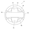
- FIG. 1 is a bottom view of a shaped member for an engine piston according to an embodiment of the present invention.
- FIG. 2 is a front view of the allomorphic material.
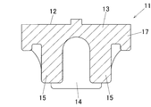
- 3 is a cross-sectional view taken along line XX in FIG.
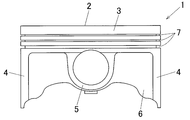
- FIG. 4 is a front view of an engine piston manufactured from an allomorphic material.
- FIG. 5 is a schematic cross-sectional view of a horizontal continuous casting apparatus.
- FIG. 6 is a schematic cross-sectional view of a hot top continuous casting apparatus.
- FIG. 7 is a cross-sectional view of a die of a forging device showing an example of a process for forging a forging material using the forging device.
- FIG. 1 is a bottom view of a shaped member for an engine piston according to an embodiment of the present invention.
- FIG. 2 is a front view of the allomorphic material.
- 3 is a cross-sectional view taken along line XX in FIG.
- FIG. 4 is a front view
- FIG. 8 is a cross-sectional view of the mold of the forging device showing another example of the process of forging the forging material using the forging device.
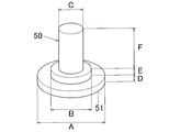
- FIG. 9 is a perspective view of an analytical sample of a molten aluminum alloy.
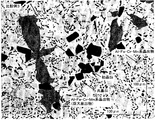
- FIG. 10 is a structural photograph of Example 1 taken by microstructural observation.
- FIG. 11 is a structure photograph of Comparative Example 3 imaged by microstructure observation.
- FIG. 12 is a diagram showing the relationship between the P addition amount and the Si addition amount in Examples 9 to 12 and Comparative Examples 17 to 24.
- excellent in high temperature characteristics means that the strength at 250 ° C. is excellent, that is, the fatigue strength (ie, high temperature fatigue strength) at 250 ° C. when the tensile strength (ie, high temperature tensile strength) is 120 MPa or more. Means 60 MPa or more.
- reference numeral 11 denotes an aluminum piston engine piston shaped material according to an embodiment of the present invention.
- reference numeral 1 denotes an aluminum alloy engine piston manufactured from the base material 11.
- the vertical direction toward the paper surface of FIG. 1 is referred to as “front-rear direction”, the horizontal direction is referred to as “left-right direction”, and the vertical direction toward the paper surface of FIGS. To do.
- the engine piston 1 includes a crown surface portion 2 having a circular shape in plan view, a land portion 3 formed on the lower side, and a pair of skirt portions 4 disposed on the lower side so as to face each other.
- a pair of pin boss portions 5 and sidewall portions 6 are integrally provided.
- a plurality of piston ring groove portions 7 to which a plurality of piston rings (eg, pressure rings, oil rings) are attached are formed on the outer peripheral surface of the land portion 3.
- the engine piston blank 11 is manufactured by forging, and, like the engine piston 1, is a portion corresponding to the crown surface portion 2 (that is, the crown surface portion corresponding portion 12). And a land portion corresponding portion 13 formed on the lower side, a pair of skirt portion corresponding portions 14 and 14, a pair of pin boss portion corresponding portions 15 and 15 and a sidewall portion disposed on the lower side. Corresponding portions 16 and 16 are integrally provided.
- the outer peripheral surface of the land portion corresponding portion 13 and the vicinity of the inside thereof are portions where a plurality of piston ring groove portions 7 are formed at the time of final finishing, that is, constitute the piston ring groove portion corresponding portion 17.
- This raw material 11 has primary Si at least in the skirt portion corresponding portion 14 and the piston ring groove portion corresponding portion 17. Furthermore, in the entire raw material, there is no primary crystal Si having a maximum diameter of 50 ⁇ m or more, and no Al—Fe—Cr—Mn giant crystallized material having a maximum diameter of 50 ⁇ m or more. Furthermore, there is no segregation of primary crystal Si in the whole raw material.
- “primary crystal Si is present” specifically means that, for example, when a sample is mirror-polished and then this mirror-polished surface is observed with a microstructure using a metal microscope, ash It indicates the presence of brown, block-like crystallization products.
- the maximum diameter of primary Si is the diameter measured at the maximum primary Si.
- the maximum diameter of the Al—Fe—Cr—Mn giant crystallized product is the diameter measured at the maximum part of the giant crystallized product.
- the maximum diameter of the primary crystal Si can be obtained by setting the primary crystal Si and measuring the maximum length of the crystallized product using an image analyzer.
- image analysis device for example, LUZEX manufactured by Nireco Corporation is used.
- the maximum diameter of the Al—Fe—Cr—Mn giant crystallized product for example, when a sample is mirror-polished and then this mirror-polished surface is observed with a metallographic microscope, a thin structure is obtained.
- the gray crystallized product is an Al—Fe—Cr—Mn based giant crystallized product, and the maximum length of the giant crystallized product is measured by using an image analysis device.
- the maximum diameter of the crystallized product can be obtained.
- the image analysis device for example, LUZEX manufactured by Nireco Corporation is used.
- the Al—Fe—Cr—Mn based crystals having various sizes are particularly Al—Fe—Cr. -This is called a Mn-based giant crystallized product.
- the Al—Fe—Cr—Mn giant crystallized product is also called an Al—Fe—Cr—Mn giant intermetallic compound (giant soot compound).
- the criteria for determining whether or not there is segregation of primary Si is not particularly limited. However, in this embodiment, with respect to this determination criterion, 5 or more (preferably 3 or more) primary crystal Si are formed and at least one interval between each primary crystal Si is larger than the grain size of primary crystal Si. It is assumed that there is segregation of primary Si when there is a short primary crystal Si aggregate, and there is no segregation of primary Si when there is no such primary crystal Si aggregate.
- the raw material 11 is manufactured by continuously casting a molten metal having a predetermined composition to obtain a cast bar, and forging a forging material obtained by homogenizing the cast bar, And a forging step for obtaining a profile.
- the diameter of the cast bar obtained in this continuous casting process must be 85 mm or less.
- the composition of the molten metal is as follows: Si: 11.0 to 13.0 mass%, Fe: 0.6 to 1.0 mass%, Cu: 3.5 to 4.5 mass%, Mn: 0.25 mass% or less, Mg: 0.4 to 0.6 mass%, Cr: 0.15 mass% or less, Ni: 0.6 to ⁇ ( ⁇ 4/6) ⁇ [Cu mass%] + 5 ⁇ mass%, Zr: 0.07 -0.15 mass%, P: 0.005-0.010 mass%, Ca: 0.002 mass% or less, the balance being Al and inevitable impurities.
- the forging material In the forging process, the forging material must be homogenized at a temperature of 300 to 500 ° C.
- Si is an element that suppresses the thermal expansion of the aluminum alloy and improves the wear resistance. That is, the wear resistance can be improved by controlling the crystallization of primary Si to an appropriate state.
- an appropriate coefficient of thermal expansion is determined by the material of the mating member for the engine piston 1, that is, the material of the cylinder block (iron, aluminum), but the cylinder block partially rises to a high temperature. As a whole, since the temperature does not become high (and it takes time to reach high temperature), it is advantageous that the coefficient of thermal expansion is as small as possible.
- the design of the engine piston 1 and the selection of the piston ring are designed with dimensions when the engine reaches a high temperature. Therefore, if the thermal expansion is too large, the diameter of the skirt portion 4 becomes small at a low temperature, and the swing of the engine piston 1 is likely to occur at the start. Therefore, it is desirable that the amount of Si added is as large as possible because thermal expansion can be reduced.
- a preferable thermal expansion coefficient is 19 ⁇ 10 ⁇ 6 / K to 21 ⁇ 10 ⁇ 6 / K in the range of 25 to 250 ° C., and the addition amount of Si that can obtain such a thermal expansion coefficient is 11.0 to 13 0.0% by mass.
- the inventors have specified alloy composition conditions that provide excellent high-temperature strength and high-temperature fatigue strength while maintaining wear resistance even when adding amounts of Si before and after sandwiching the eutectic point. Manufacturing conditions were found and the present invention was completed.
- the primary crystal Si is stably formed even when Si is added in amounts before and after the eutectic point due to the interaction with them. Since it crystallizes, the wear resistance can be improved. More preferably, the addition amount of Si should exceed 12.0% by mass.
- the amount of Si added exceeds 13% by mass, the crystallized primary crystal Si is segregated, which becomes the starting point of fatigue fracture and lowers the high temperature fatigue strength, which is not desirable.
- Fe About 0.6 to 1.0% by mass> Fe crystallizes as an Al—Fe—Cr—Mn intermetallic compound together with Cr, Mn, and the like, and this crystallized substance becomes a stable dispersion strengthening phase even at a high temperature and contributes to an improvement in high temperature strength.
- the added amount of Fe is less than 0.6% by mass, the amount of the dispersion strengthening phase is small and the improvement in high temperature strength is small, which is not desirable.
- an Al—Fe—Cr—Mn giant crystallized product may be crystallized, which may reduce high temperature fatigue strength. Therefore, in the present invention, when the total addition amount of Fe, Cr, and Mn is large, it is particularly desirable to add the total addition amount of Cr and Mn to 40% or less with respect to the addition amount of Fe. By doing so, crystallization of the giant crystallized product can be suppressed even if the amount of Fe added is large.
- Fe crystallizes Al—Fe—Ni—Cu intermetallic compounds that are stable at high temperatures together with Al, Fe and Ni, and contributes to improvement of high temperature strength.
- ⁇ Cu About 3.5 to 4.5 mass%> Cu precipitates as an Al—Cu (—Mg) -based intermetallic compound, and its presence improves strength and fatigue strength at 150 ° C. or lower (hereinafter abbreviated as normal temperature strength and normal temperature fatigue strength, respectively).
- the amount of Cu added is less than 3.5% by mass, the amount of Al—Cu (—Mg) intermetallic compound precipitates is small, and the amount of Al—Fe—Ni—Cu intermetallic compound crystallized material Since there is little improvement in normal temperature strength and normal temperature fatigue strength, it is not desirable.
- Mn is crystallized as an intermetallic compound together with Fe and Cr and becomes a dispersion strengthening phase, and is an element that contributes to the improvement of high-temperature strength, but it is easier to produce Al-Fe-Cr-Mn-based giant crystals than Fe. . Therefore, the amount of Mn added is set to 0.25% by mass or less. The amount of Mn added is desirably as small as possible, and particularly preferably below the detection limit. The most desirable amount of Mn added is 0% by mass.
- Mg is an element that improves normal temperature strength and normal temperature fatigue strength by coexisting with Si and Cu. If the addition amount of Mg is less than 0.4% by mass, the above effect is poor, which is undesirable. Even if Mg is added in excess of 0.6% by mass, the above effect is saturated. Therefore, the amount of Mg added is set to 0.4 to 0.6% by mass.
- ⁇ Cr About 0.15 mass% or less> Cr crystallizes as an intermetallic compound together with Fe and Mn, becomes a dispersion strengthening phase, and is an element that contributes to the improvement of high-temperature strength. However, it is easier to produce Al—Fe—Cr—Mn giant crystallized products than Fe. . Therefore, the addition amount of Cr is set to 0.15% by mass or less. The addition amount of Cr is preferably as small as possible, and particularly preferably below the detection limit. The most desirable addition amount of Cr is 0% by mass.
- Ni crystallizes an Al—Fe—Ni—Cu intermetallic compound that is stable at high temperatures together with Cu, and improves high temperature strength and high temperature fatigue strength. It is desirable that there are as many such crystals as possible. However, if the amount of Ni added is less than 0.6% by mass, the above effect is poor, which is not desirable. Therefore, the addition amount of Ni is set to 0.6% by mass or more. On the other hand, if the added amount of Ni increases and exceeds ⁇ ( ⁇ 4/6) ⁇ [Cu mass%] + 5 ⁇ mass%, it is not desirable because cracks occur during forging.
- the upper limit of the amount of Ni added is set to ⁇ ( ⁇ 4/6) ⁇ [Cu mass%] + 5 ⁇ mass%. Therefore, when the addition amount of Cu is 3.5% by mass which is the lower limit, the upper limit value of the addition amount of Ni is 2.7% by mass. Moreover, when the addition amount of Cu is the upper limit of 4.5 mass%, the upper limit value of the addition amount of Ni is 2.0 mass%.
- Zr is an element that precipitates an Al—Zr intermetallic compound at a temperature of 350 ° C. or higher and improves the high-temperature strength of the alloy material. If the amount of Zr added is less than 0.07% by mass, the above effect is poor and undesirable. Even if Zr is added in an amount exceeding 0.15% by mass, the above effect is saturated. Therefore, the amount of Zr added is set to 0.07 to 0.15% by mass.
- P is an element that shifts the lower limit of the amount of Si added to crystallize primary Si to the low Si content side and further refines the grain size of the crystallized product of primary Si.
- the Si addition amount is high, the primary crystal Si becomes coarse unless P is added. If the addition amount of P is less than 0.005% by mass, the above effect is poor, which is not desirable. On the other hand, if the addition amount of P exceeds 0.010% by mass, the above effect is saturated, and further, the needle-like formation of eutectic Si is promoted and the toughness is lowered. Therefore, the addition amount of P is set to 0.005 to 0.010 mass%. By doing in this way, the maximum diameter of primary crystal Si can be 50 micrometers or less.
- the addition amount of P satisfies the following formula (1).
- crystallization of primary Si by continuous casting can be reliably stabilized.
- primary Si can be surely present throughout the entire shape material, segregation of primary Si can be reliably prevented, and eutectic Si can be spheroidized reliably. Can do.
- P has a small amount of P dissolved in the molten metal (that is, the amount of P added), and handling is troublesome. Therefore, in order to increase the amount of addition of P and facilitate handling, it is preferable to add P to the molten metal in the form of a P—Cu alloy (a master alloy of 8 mass% P and 92 mass% Cu).
- Ca is an element that inhibits the refinement and hardening of primary Si by P. Therefore, a flux containing magnesium chloride (MgCl 2 ) is charged into the molten metal and stirred, so that the amount of Ca in the molten metal is decreased and the amount of Ca added is controlled to be 0.002% by mass or less. More preferably, by defining the addition amount of Ca and P (unit: mass%) as P> 6 ⁇ Ca, even when adding Si before and after the eutectic point, P is consumed by Ca. Not.
- the addition amount of Ca is preferably as small as possible, and particularly preferably below the detection limit.
- the most desirable addition amount of Ca is 0% by mass.
- the reason why the molten metal temperature was set to 720 ° C. or higher in the continuous casting process is as follows.
- casting temperature shall be 720 degreeC or more. This can be realized by setting the melt temperature before pouring the continuous casting mold to 720 ° C. or higher. A particularly preferable molten metal temperature is 740 ° C. or higher.
- the upper limit of molten metal temperature is not specifically limited, For example, it is 850 degreeC (preferably 750 degreeC).
- the reason why the diameter of the cast bar was set to 85 mm or less in the continuous casting process is as follows.
- the cooling rate at the center of the ingot slows down, so that Al-Fe-Cr-Mn-based giant crystals are likely to be generated, and further, at the center of the cast bar.
- the refinement and uniform distribution of primary Si are hindered.
- the diameter of the casting rod is 85 mm or less, the difference in cooling rate between the center portion and the outer peripheral portion of the casting rod can be kept small, and preferably this cooling rate difference can be made 200 ° C./s or less. As a result, the formation of Al—Fe—Cr—Mn giant crystallized product can be suppressed. For this reason, the diameter of the cast bar is regulated to 85 mm or less.
- the forging material obtained by homogenizing the casting rod is forged into the shaped material for the engine piston, Al is formed at the center of the casting rod corresponding to the crown surface portion 2 of the engine piston 1.
- the —Fe—Cr—Mn-based giant crystallized product does not exist, and the crystallized state of primary Si can be made fine and uniform with a maximum diameter of less than 50 ⁇ m.
- the lower limit of the diameter of a casting rod is not specifically limited, For example, it is 20 mm.
- the reason for homogenizing the cast bar at 300 to 500 ° C is as follows.
- the homogenization treatment directly under the solidus temperature which is generally performed for improving forgeability, has a high processing temperature, and Al-Si-based crystals and Al-Fe-Cr-Mn-based crystals To spheroidize and reduce the area of the interface. Therefore, in the present invention, the upper limit of the treatment temperature is set to a temperature at which the Al—Si-based crystallized product and the Al—Fe—Cr—Mn-based crystallized product are not divided or spheroidized. However, if the homogenization temperature is too low, the deformability is insufficient during forging, and defects such as cracks occur.
- the homogenization temperature is set to 300 to 500 ° C., and more preferably, the temperature is set as low as possible within the range in which the material is not broken during forging in accordance with the shape of the engine piston.
- the homogenization time is preferably 4 hours or longer. By homogenizing the cast rod under such processing conditions, it is possible to reliably maintain an Al-Si-based crystallized product or an Al-Fe-Cr-Mn-based crystallized product that is not divided or spheroidized. .
- the upper limit of the holding time of the homogenization processing time is not particularly limited, and is, for example, within 24 hours.
- the continuous casting apparatus is not limited to that method as long as it can obtain a casting rod having a diameter of 85 mm or less while maintaining the molten metal temperature at 720 ° C. or higher.
- a vertical semi-continuous casting apparatus For example, a vertical semi-continuous casting apparatus.
- a hot top continuous casting apparatus, a horizontal continuous casting apparatus, and a gas pressure type continuous casting apparatus can be used.
- FIG. 5 is a cross-sectional view showing an example of a horizontal continuous casting apparatus that performs horizontal continuous casting.
- the continuous casting apparatus 20A includes a molten metal receiving part 21 for storing a molten aluminum alloy 30 and a solidification continuous casting water cooling mold (water cooling mold) 22 having a molten metal passage 22a.
- the mold 22 is arrange
- Reference numeral 24 denotes a cooling water passage formed in the mold 22.
- the mold 22 and the casting rod 31 drawn from the mold 22 are cooled by the cooling water 25 discharged from the cooling water passage 24.
- FIG. 6 is a cross-sectional view showing an example of a hot top continuous casting apparatus.
- This continuous casting apparatus 20B includes a molten metal receiving portion 21 and a continuous casting water-cooling mold 22 for solidification that is disposed below the molten metal receiving portion 21 and has a molten metal passage 22a. And the mold 22 is arranged in the molten state through the molten metal inlet 23 through the molten metal receiving portion 21 and the outlet of the molten metal passage 22a is directed downward.
- the molten aluminum alloy 30 in the molten metal receiving portion 21 is introduced into the cooled mold 22 through the molten metal inlet 23 from above.
- the molten metal 30 introduced into the mold 22 is drawn downward from the mold 22 while forming a strong shell (solidified shell) at a portion in contact with the mold 22.
- the casting rod 31 drawn out from the mold 22 is cooled by the cooling water 25 discharged from the cooling water passage 24.
- the temperature at the position C immediately before the molten metal 30 is poured into the mold 22 is the molten metal temperature, and this temperature is 720 ° C. or higher. Is good.
- the temperature at this position C in the molten metal 30 is set as the molten metal temperature.
- Any homogenization heat treatment furnace may be used as long as it can accommodate a casting rod and can perform a homogenization treatment at a treatment temperature of 300 to 500 ° C., for example, a hot air circulation type furnace.
- a furnace either a direct furnace or a radiant tube furnace may be used, and in the case of a transfer type furnace, either a continuous furnace or a batch furnace may be used.
- Any forging device may be used as long as it has a forging die for forging a forging material into an engine piston-shaped material, and in particular, a forging device further provided with a preheating treatment device and a lubricant coating device. desirable.
- the forging die is desirably a closed forging die. Specifically, a knuckle press, a crank press, a friction press, a hydraulic press, and a servo press can be used as the forging device.
- the manufacturing method of the shaped material in the present embodiment is performed as follows.
- a molten metal having a predetermined composition is continuously cast into a casting rod having a molten metal temperature of 720 ° C. or more and a diameter of 85 mm or less [continuous casting process].
- the cross-sectional shape of the cast bar is preferably circular, that is, the cast bar is preferably round.
- the forging material is obtained by homogenizing the cast bar at a temperature of 300 to 500 ° C. And as for this raw material, the outer peripheral surface of a raw material is peel-processed (peripheral surface cutting process) as needed after the homogenization process. Thereafter, the material is cut into a predetermined length (thickness) in the length direction of the material, thereby forming a disk shape or a cylindrical shape.
- the cut surface of the cast bar becomes the upper surface and the lower surface of the material, and the outer peripheral surface of the cast bar or the vicinity thereof becomes the outer peripheral surface of the material. Further, this material is subjected to upsetting treatment, lubrication treatment and preheating treatment as necessary.
- the material is forged into an engine piston-shaped material by a forging device [forging process].
- FIG. 7 and 8 are diagrams showing a forging process in which a material is forged using a forging device.
- a die 41 of the forging device 40 shown in FIGS. 7 and 8 is composed of an upper die 42 and a lower die 43, and the upper and lower dies 42, 43 are fitted together to form a sealed molding space 44.
- the disk-shaped or columnar material 32 is forged inside, and the raw material 11 for the engine piston is obtained.
- 32A is a long forging bar-shaped material 32A obtained by homogenizing the casting bar 31.
- the disc-shaped or columnar material 32 obtained by cutting the rod-shaped material 32A into a predetermined length (thickness) is disposed in the lower mold 43 of the forging device 40 and then fitted into the lower mold 43.
- the upper die 42 is pressed in the axial direction of the raw material 32, the raw material 32 is forged into a predetermined shape in the sealed molding space 44, and the shaped material 11 for the engine piston is obtained.
- a die 41 of the forging device 40 shown in FIG. 7 is configured such that a skirt portion corresponding portion (not shown) and pin boss portion corresponding portions 15 and 15 are forward-extruded.
- the raw material 32 is forged in the same manner as the forging method shown in FIG.
- the die 41 of the forging device 40 shown in FIG. 8 is configured such that a skirt portion corresponding portion (not shown) and pin boss portion corresponding portions 15 and 15 are rearwardly extruded.
- the material 32 is such that the upper surface or the lower surface of the material 32 becomes the crown surface corresponding portion 12 of the base material 11, and the outer peripheral portion of the material 32 is the piston ring groove corresponding portion 17. And it arrange
- the treatment temperature of the preheating treatment performed immediately before forging and the raw material temperature during forging are preferably 470 ° C. or less and as short as possible, and particularly preferably lower than the homogenization treatment temperature.
- the heating time may be the shortest time during which the material temperature can be raised to the processing temperature (ie, 470 ° C. or lower).
- the raw material 11 thus obtained is subjected to a solution treatment and an aging treatment as necessary.
- the solution treatment temperature is not higher than the solidus temperature. The reason is that the state of the Al—Si based crystallized product and the Al—Fe—Cr—Mn based crystallized product after the homogenization treatment can be maintained.
- the aging temperature and aging time be slightly over-aged by adjusting the temperature and time. By doing so, dimensional growth due to aging during product use can be suppressed.
- the base material 11 is subjected to final finishing by machining or the like, and then other parts such as a piston ring are attached to become an engine piston.
- the base material 11 manufactured according to the base material manufacturing method of the present embodiment does not generate cracks in the crown surface corresponding part 12 during forging, and at least the skirt part corresponding part 14 and the piston ring groove part corresponding part.
- primary Si is appropriately present, primary Si having a maximum diameter of 50 ⁇ m or more is not present, segregation of primary Si is not present, and an Al—Fe—Cr—Mn giant crystal having a maximum diameter of 50 ⁇ m or more is formed. Things do not exist. Therefore, the engine piston 1 manufactured using this shaped material 11 is excellent in wear resistance and further excellent in normal temperature tensile characteristics and high temperature characteristics (that is, high temperature tensile characteristics and high temperature fatigue characteristics).
- the unit of the composition element is “mass%”.
- A means ⁇ ( ⁇ 4/6) ⁇ [Cu mass%] + 5 ⁇ mass%.
- a round bar-shaped cast bar was obtained by continuously casting a molten Al alloy having the composition shown in Table 1 using a hot top continuous casting apparatus (see FIG. 6).
- the melt temperature before pouring the continuous casting mold is as described in the “melt temperature” column of Table 2.
- the diameter of the obtained cast bar is as described in the column “Diameter of cast bar” in Table 2.
- an analytical sample 50 having a substantially disk shape as shown in FIG. 9 is collected by casting a molten metal into a mold in accordance with JIS Z 2611.
- the analytical sample 50 is used to comply with JIS H 1305.
- the constituent elements of the molten metal were quantitatively analyzed by emission spectroscopic analysis.
- reference numeral 51 denotes an analysis unit for the analysis sample 50.
- the analysis unit 51 was cut by about 0.5 mm (0.3 to 0.6 mm) with a milling machine and then used for analysis. About the dimension of each site
- the cast rod was cut into a length of 6000 mm.
- the cut cast bar was homogenized.
- the treatment temperature is as described in the “homogenization treatment temperature” column in Table 2.
- the processing time is 7 hours.
- the outer circumference of the cast bar was cut to a diameter of 50 mm, and the cast bar was further cut to a length of 60 mm to obtain a cylindrical forging material.
- This upset forging corresponds to the forging in the forging process of the present invention, and was carried out at a forging rate corresponding to the forging rate when the material was actually forged into an engine piston blank.
- the upset forged product was T6 heat treated. That is, the upset forged product was solution-treated at 495 ° C., and then artificially aged under the conditions of an aging temperature of 200 ° C. and an aging time of 6 hours.
- the upset forged product thus subjected to the T6 heat treatment was examined by visual observation for the presence of cracks and hole defects on the surface of the upset forged product by a solvent-removable penetration test (color check). After that, the upset forged product is cut, the cross section is mirror-polished, and the microstructure of the mirror-polished surface from the center to the outer periphery of the upset forged product is observed using a metal microscope.
- the presence / absence, presence / absence of primary crystal Si having a maximum diameter of 50 ⁇ m or more, presence / absence of Al—Fe—Cr—Mn-based giant crystallized substances, and segregation of primary crystal Si were examined.
- FIG. 10 shows a structure photograph of Example 1 as a representative example of the structure photographs of Examples 1 to 8 taken by microstructural observation.
- FIG. 11 shows a structure photograph of Comparative Example 3 as a representative example of the structure photographs of Comparative Examples 1 to 16 taken by microstructural observation.
- LUZEX manufactured by Nireco Co., Ltd. was used as an image analysis apparatus for analyzing the image of the tissue photograph.
- the Al—Fe—Cr—Mn crystallized product is a light gray crystallized product
- the primary crystal Si is a grayish brown and block crystallized product
- the eutectic Si is more than the primary crystal Si. It is a grayish brown crystallization product with a small average particle size of about 5 ⁇ m.
- the Al—Fe—Ni—Cu based crystals are Al—Fe—Cr—Mn based crystals in the structure photograph. It is observed as a gray crystallized product that is lighter than the product.
- a large amount of eutectic Si is present in a dispersed state, and the average particle size is about 5 ⁇ m.
- a plurality of primary crystal Si are present in a dispersed state, the maximum diameter is about 25 ⁇ m, and the average particle diameter is about 20 ⁇ m, but there is no primary crystal Si having a maximum diameter of 50 ⁇ m or more.
- a large number of Al-Fe-Cr-Mn crystals are dispersed and the average particle size is about 5 ⁇ m, but the Al—Fe—Cr—Mn macrocrystals having a maximum diameter of 50 ⁇ m or more. There are no artifacts.
- a large number of Al—Fe—Ni—Cu based crystals are dispersed and the average particle size is about 5 ⁇ m.
- FIG. 11 Comparative Example 3
- a large amount of eutectic Si is present in a dispersed state, and the average particle size is about 5 ⁇ m.
- Primary crystal Si is unevenly distributed, its maximum diameter is about 35 ⁇ m, and its average particle size is about 20 ⁇ m.
- the evaluation method of room temperature tensile properties is as follows.
- JIS14A proportional test piece was sampled from upset forged product subjected to T6 heat treatment, and the tensile strength at 25 ° C. was measured with this test piece. And the tensile strength of 350 MPa or more was considered good, and less than 350 MPa was judged as defective. The results are shown in the “room temperature tensile properties” column of Table 2.
- the evaluation method of high temperature tensile properties is as follows.
- the evaluation method of high temperature fatigue characteristics is as follows.
- Comparative Example 14 since the homogenization temperature was too high, eutectic melting occurred during preheating before upsetting forging, and cracks occurred starting from the melting portion during upsetting forging.
- the unit of the composition element is “mass%”.
- A means ⁇ ( ⁇ 4/6) ⁇ [Cu mass%] + 5 ⁇ mass%.
- FIG. 12 is a graph showing the relationship between the P addition amount and the Si addition amount in Examples 9 to 12 and Comparative Examples 17 to 24.
- [P] means the amount of P added (unit: mass%)
- [Si] means the amount of Si added (unit: mass%).
- a round bar-shaped cast bar was obtained by continuously casting a molten Al alloy having the composition shown in Table 3 using a hot top continuous casting apparatus (see FIG. 6).
- the molten metal temperature before pouring the continuous casting mold was 750 ° C.
- the diameter of the casting rod was 55 mm.
- an analytical sample 50 having a substantially disk shape as shown in FIG. 9 is collected by casting a molten metal into a mold in accordance with JIS Z 2611.
- the analytical sample 50 is used to comply with JIS H 1305. Then, the constituent elements of the molten metal were quantitatively analyzed by emission spectroscopic analysis.
- the cast rod was cut into a length of 6000 mm.
- the cut cast bar was homogenized under the conditions of a processing temperature of 470 ° C. and a holding time of 7 hours.
- the outer circumference of the cast bar was cut to a diameter of 50 mm, and the cast bar was further cut to a length of 60 mm to obtain a cylindrical forging material.
- This upset forging corresponds to the forging in the forging process of the present invention, and was carried out at a forging rate corresponding to the forging rate when the material was actually forged into an engine piston blank.
- the upset forged product was T6 heat treated. That is, the upset forged product was solution-treated at 495 ° C., and then artificially aged under the conditions of an aging temperature of 200 ° C. and an aging time of 6 hours.
- the presence or absence of primary Si was judged by the presence of grayish brown block-like crystallization products when the microstructure was observed.
- primary Si aggregates formed by gathering 3 or more primary Si and having at least one interval between the primary Si shorter than the grain size of primary Si. In this case, segregation of primary Si was allowed, and when there was no such primary crystal Si aggregate, segregation of primary Si was absent.
- Eutectic Si is a grayish brown crystallization product smaller than primary Si.
- maximum length / “minimum length” was 3 or more, it was determined that eutectic Si was acicular, and if it was less than 3, It was judged that crystal Si was spheroidized.
- the Si addition amount is in the range of 11.0 to 13.0 mass%, and the P addition amount is 0.005 to 0.010 mass%. Further, the P addition amount satisfies the above formula (1). Therefore, the crystallization of primary Si by continuous casting became stable. As a result, primary Si was present from the center to the outer periphery of the upset forged product, and there was no segregation of primary Si. Further, eutectic Si was spheroidized. Therefore, it had a good microstructure.
- Comparative Example 18 although the Si content was within the range of the present invention, the amount of P added was small, so that primary Si was present only at the center of the upset forged product, and primary Si was present at the outer periphery. Did not exist.
- the term present invention or inventory should not be improperly interpreted as identifying criticality, nor should it be improperly interpreted as applying across all aspects or all embodiments ( That is, it should be understood that the present invention has numerous aspects and embodiments) and should not be construed inappropriately to limit the scope of the present application or the claims.
- the term “embodiment” is also used to describe any aspect, feature, process or step, any combination thereof, and / or any part thereof. It is done. In some examples, various embodiments may include overlapping features.
- the abbreviations “e.g.,” and “NB” may be used, meaning “for example” and “careful”, respectively.
- the present invention can be used for a manufacturing method of a raw material for manufacturing an engine piston used for an engine mounted on a vehicle such as an automobile or a motorcycle, and a raw material for an engine piston.
- Engine piston 2 Crown surface portion 4: Skirt portion 7: Piston ring groove portion 11: Engine piston shaped material 12: Crown surface portion corresponding portion 14: Skirt portion corresponding portion 17: Piston ring portion corresponding portion 20A: Horizontal continuous casting apparatus 20B: Hot Top Continuous Casting Device 22: Continuous Casting Mold 30: Molten Metal 31: Casting Rod 32: Forging Material 40: Forging Device
Landscapes
- Chemical & Material Sciences (AREA)
- Engineering & Computer Science (AREA)
- Mechanical Engineering (AREA)
- Materials Engineering (AREA)
- Metallurgy (AREA)
- Organic Chemistry (AREA)
- Physics & Mathematics (AREA)
- Thermal Sciences (AREA)
- Crystallography & Structural Chemistry (AREA)
- Pistons, Piston Rings, And Cylinders (AREA)
Abstract
Cette invention concerne un procédé de production d'un matériau proche de la forme finale pour un piston de moteur, comprenant : une étape de coulée continue permettant d'obtenir une tige coulée (31) d'un diamètre inférieur ou égal à 85 mm par coulée continue d'un bain (30) d'alliage d'aluminium à une température de coulée supérieure ou égale à 720°C ; et une étape de forgeage permettant d'obtenir un matériau proche de la forme finale (11) pour un piston de moteur en forgeant un matériau destiné au forgeage (32) obtenu par homogénéisation de la tige coulée (31) à une température de 300 à 500°C. Le bain (30) a une composition contenant de 11,0 à 13,0% de Si, de 0,6 à 1,0% de Fe, de 3,5 à 4,5% de Cu, une proportion de Mn inférieure ou égale à 0,25%, de 0,4 à 0,6% de Mg, une proportion de Cr inférieure ou égale à 0,15%, de 0,6% à {(-4/6) × [Cu en % massique] + 5}% de Ni, de 0,07 à 0,15% de Zr, de 0,005 à 0,010% de P, et une proportion inférieure ou égale à 0,002 % en masse de Ca, le reste étant de l'Al et des impuretés inévitables.
Priority Applications (1)
| Application Number | Priority Date | Filing Date | Title |
|---|---|---|---|
| JP2011538491A JP5689423B2 (ja) | 2009-10-30 | 2010-10-29 | エンジンピストン用素形材の製造方法 |
Applications Claiming Priority (2)
| Application Number | Priority Date | Filing Date | Title |
|---|---|---|---|
| JP2009-250278 | 2009-10-30 | ||
| JP2009250278 | 2009-10-30 |
Publications (1)
| Publication Number | Publication Date |
|---|---|
| WO2011052708A1 true WO2011052708A1 (fr) | 2011-05-05 |
Family
ID=43922129
Family Applications (1)
| Application Number | Title | Priority Date | Filing Date |
|---|---|---|---|
| PCT/JP2010/069255 Ceased WO2011052708A1 (fr) | 2009-10-30 | 2010-10-29 | Procédé de production d'un matériau proche de la forme finale pour piston de moteur |
Country Status (2)
| Country | Link |
|---|---|
| JP (1) | JP5689423B2 (fr) |
| WO (1) | WO2011052708A1 (fr) |
Cited By (5)
| Publication number | Priority date | Publication date | Assignee | Title |
|---|---|---|---|---|
| WO2013086881A1 (fr) * | 2011-12-12 | 2013-06-20 | Xie Zhaozong | Équipement et procédé de transformation pour coulée continue de métal |
| JP2015529779A (ja) * | 2012-09-18 | 2015-10-08 | フェデラル−モーグル コーポレイション | カウンターボアのデザインを有するスチール製ピストン |
| JP2021011595A (ja) * | 2019-07-04 | 2021-02-04 | 昭和電工株式会社 | アルミニウム合金材 |
| JP2021011604A (ja) * | 2019-07-05 | 2021-02-04 | 昭和電工株式会社 | アルミニウム合金材およびアルミニウム合金鍛造品の製造方法 |
| WO2024249153A1 (fr) * | 2023-05-31 | 2024-12-05 | Novelis Inc. | Alliage coulé en continu pour applications en feuille |
Citations (5)
| Publication number | Priority date | Publication date | Assignee | Title |
|---|---|---|---|---|
| JPH10226840A (ja) * | 1997-02-19 | 1998-08-25 | Unisia Jecs Corp | ピストン用アルミニウム合金 |
| JP2003035198A (ja) * | 2001-07-23 | 2003-02-07 | Showa Denko Kk | 内燃機関用ピストンおよびその製造方法 |
| JP2004068152A (ja) * | 2002-07-22 | 2004-03-04 | Toyota Central Res & Dev Lab Inc | アルミニウム鋳造合金製ピストン及びその製造方法 |
| JP2005290545A (ja) * | 2003-12-18 | 2005-10-20 | Showa Denko Kk | アルミニウム合金成形品の製造方法、アルミニウム合金成形品および生産システム |
| WO2008016169A1 (fr) * | 2006-08-01 | 2008-02-07 | Showa Denko K.K. | Procédé de production de pièces forgées en alliage d'aluminium, pièces forgées en alliage d'aluminium et système de production |
-
2010
- 2010-10-29 WO PCT/JP2010/069255 patent/WO2011052708A1/fr not_active Ceased
- 2010-10-29 JP JP2011538491A patent/JP5689423B2/ja not_active Expired - Fee Related
Patent Citations (5)
| Publication number | Priority date | Publication date | Assignee | Title |
|---|---|---|---|---|
| JPH10226840A (ja) * | 1997-02-19 | 1998-08-25 | Unisia Jecs Corp | ピストン用アルミニウム合金 |
| JP2003035198A (ja) * | 2001-07-23 | 2003-02-07 | Showa Denko Kk | 内燃機関用ピストンおよびその製造方法 |
| JP2004068152A (ja) * | 2002-07-22 | 2004-03-04 | Toyota Central Res & Dev Lab Inc | アルミニウム鋳造合金製ピストン及びその製造方法 |
| JP2005290545A (ja) * | 2003-12-18 | 2005-10-20 | Showa Denko Kk | アルミニウム合金成形品の製造方法、アルミニウム合金成形品および生産システム |
| WO2008016169A1 (fr) * | 2006-08-01 | 2008-02-07 | Showa Denko K.K. | Procédé de production de pièces forgées en alliage d'aluminium, pièces forgées en alliage d'aluminium et système de production |
Cited By (5)
| Publication number | Priority date | Publication date | Assignee | Title |
|---|---|---|---|---|
| WO2013086881A1 (fr) * | 2011-12-12 | 2013-06-20 | Xie Zhaozong | Équipement et procédé de transformation pour coulée continue de métal |
| JP2015529779A (ja) * | 2012-09-18 | 2015-10-08 | フェデラル−モーグル コーポレイション | カウンターボアのデザインを有するスチール製ピストン |
| JP2021011595A (ja) * | 2019-07-04 | 2021-02-04 | 昭和電工株式会社 | アルミニウム合金材 |
| JP2021011604A (ja) * | 2019-07-05 | 2021-02-04 | 昭和電工株式会社 | アルミニウム合金材およびアルミニウム合金鍛造品の製造方法 |
| WO2024249153A1 (fr) * | 2023-05-31 | 2024-12-05 | Novelis Inc. | Alliage coulé en continu pour applications en feuille |
Also Published As
| Publication number | Publication date |
|---|---|
| JP5689423B2 (ja) | 2015-03-25 |
| JPWO2011052708A1 (ja) | 2013-03-21 |
Similar Documents
| Publication | Publication Date | Title |
|---|---|---|
| JP5526130B2 (ja) | エンジンピストン用素形材の製造方法 | |
| JP5027844B2 (ja) | アルミニウム合金成形品の製造方法 | |
| EP2085491B1 (fr) | Matériau d'alliage d'aluminium résistant à l'usure avec une excellente aptitude au façonnage et procédé de production de ce dernier | |
| CN1283822C (zh) | 制造镁合金产品的方法 | |
| US7682469B2 (en) | Piston made of aluminum cast alloy and method of manufacturing the same | |
| JP4359231B2 (ja) | アルミニウム合金成形品の製造方法、およびアルミニウム合金成形品 | |
| JP5689423B2 (ja) | エンジンピストン用素形材の製造方法 | |
| JP7533746B2 (ja) | アルミニウム合金鍛造用素材、アルミニウム合金製鍛造品及びその製造方法 | |
| JP4511156B2 (ja) | アルミニウム合金の製造方法と、これにより製造されるアルミニウム合金、棒状材、摺動部品、鍛造成形品および機械加工成形品 | |
| JP2001020047A (ja) | アルミニウム合金鍛造用素材およびその製造方法 | |
| GB2065516A (en) | A cast bar of an aluminum alloy for wrought products, having improved mechanical properties and workability | |
| JPH07197165A (ja) | 高耐磨耗性快削アルミニウム合金とその製造方法 | |
| JP7698520B2 (ja) | 鍛造加工品用アルミニウム合金 | |
| JP4328321B2 (ja) | 内燃機関用ピストン | |
| JP7840305B2 (ja) | アルミニウム合金製鍛造品の製造方法 | |
| JP7533743B2 (ja) | アルミニウム合金鍛造用素材、アルミニウム合金鍛造品及びその製造方法 | |
| JP6875795B2 (ja) | 内燃機関用ピストン及びその製造方法 | |
| JPH05287427A (ja) | 冷間鍛造用耐摩耗性アルミニウム合金とその製造方法 | |
| JP2012006074A (ja) | マグネシウム合金鍛造ピストンの製造方法およびマグネシウム合金鍛造ピストン | |
| JP2010132995A (ja) | エンジンまたはコンプレッサーのピストン用アルミニウム合金及びエンジンまたはコンプレッサーのピストンの鍛造方法 | |
| JP2024093687A (ja) | アルミニウム合金鍛造品及びその製造方法 | |
| JP2007092125A (ja) | アルミニウム合金、アルミニウム合金棒、鍛造用アルミニウム合金鋳塊の製造方法及び鍛造成形品 | |
| JP2004068152A (ja) | アルミニウム鋳造合金製ピストン及びその製造方法 | |
| JP2024109944A (ja) | アルミニウム合金鋳造品、アルミニウム合金鍛造品及びその製造方法 | |
| JP2025000887A (ja) | アルミニウム合金鍛造用素材、アルミニウム合金製鍛造品及びその製造方法 |
Legal Events
| Date | Code | Title | Description |
|---|---|---|---|
| 121 | Ep: the epo has been informed by wipo that ep was designated in this application |
Ref document number: 10826838 Country of ref document: EP Kind code of ref document: A1 |
|
| WWE | Wipo information: entry into national phase |
Ref document number: 2011538491 Country of ref document: JP |
|
| NENP | Non-entry into the national phase |
Ref country code: DE |
|
| 122 | Ep: pct application non-entry in european phase |
Ref document number: 10826838 Country of ref document: EP Kind code of ref document: A1 |