WO2011096018A1 - Procédé de coupe d'une pièce à travailler au moyen d'une scie à fil, et scie à fil - Google Patents
Procédé de coupe d'une pièce à travailler au moyen d'une scie à fil, et scie à fil Download PDFInfo
- Publication number
- WO2011096018A1 WO2011096018A1 PCT/JP2010/000751 JP2010000751W WO2011096018A1 WO 2011096018 A1 WO2011096018 A1 WO 2011096018A1 JP 2010000751 W JP2010000751 W JP 2010000751W WO 2011096018 A1 WO2011096018 A1 WO 2011096018A1
- Authority
- WO
- WIPO (PCT)
- Prior art keywords
- wire
- tension
- target
- target tension
- cutting
- Prior art date
- Legal status (The legal status is an assumption and is not a legal conclusion. Google has not performed a legal analysis and makes no representation as to the accuracy of the status listed.)
- Ceased
Links
Images



Classifications
-
- H—ELECTRICITY
- H10—SEMICONDUCTOR DEVICES; ELECTRIC SOLID-STATE DEVICES NOT OTHERWISE PROVIDED FOR
- H10P—GENERIC PROCESSES OR APPARATUS FOR THE MANUFACTURE OR TREATMENT OF DEVICES COVERED BY CLASS H10
- H10P52/00—Grinding, lapping or polishing of wafers, substrates or parts of devices
-
- B—PERFORMING OPERATIONS; TRANSPORTING
- B28—WORKING CEMENT, CLAY, OR STONE
- B28D—WORKING STONE OR STONE-LIKE MATERIALS
- B28D5/00—Fine working of gems, jewels, crystals, e.g. of semiconductor material; apparatus or devices therefor
- B28D5/04—Fine working of gems, jewels, crystals, e.g. of semiconductor material; apparatus or devices therefor by tools other than rotary type, e.g. reciprocating tools
- B28D5/045—Fine working of gems, jewels, crystals, e.g. of semiconductor material; apparatus or devices therefor by tools other than rotary type, e.g. reciprocating tools by cutting with wires or closed-loop blades
-
- B—PERFORMING OPERATIONS; TRANSPORTING
- B23—MACHINE TOOLS; METAL-WORKING NOT OTHERWISE PROVIDED FOR
- B23D—PLANING; SLOTTING; SHEARING; BROACHING; SAWING; FILING; SCRAPING; LIKE OPERATIONS FOR WORKING METAL BY REMOVING MATERIAL, NOT OTHERWISE PROVIDED FOR
- B23D57/00—Sawing machines or sawing devices not covered by one of the preceding groups B23D45/00 - B23D55/00
- B23D57/003—Sawing machines or sawing devices working with saw wires, characterised only by constructional features of particular parts
- B23D57/0069—Sawing machines or sawing devices working with saw wires, characterised only by constructional features of particular parts of devices for tensioning saw wires
-
- B—PERFORMING OPERATIONS; TRANSPORTING
- B24—GRINDING; POLISHING
- B24B—MACHINES, DEVICES, OR PROCESSES FOR GRINDING OR POLISHING; DRESSING OR CONDITIONING OF ABRADING SURFACES; FEEDING OF GRINDING, POLISHING, OR LAPPING AGENTS
- B24B27/00—Other grinding machines or devices
- B24B27/06—Grinders for cutting-off
-
- B—PERFORMING OPERATIONS; TRANSPORTING
- B24—GRINDING; POLISHING
- B24B—MACHINES, DEVICES, OR PROCESSES FOR GRINDING OR POLISHING; DRESSING OR CONDITIONING OF ABRADING SURFACES; FEEDING OF GRINDING, POLISHING, OR LAPPING AGENTS
- B24B27/00—Other grinding machines or devices
- B24B27/06—Grinders for cutting-off
- B24B27/0633—Grinders for cutting-off using a cutting wire
-
- B—PERFORMING OPERATIONS; TRANSPORTING
- B28—WORKING CEMENT, CLAY, OR STONE
- B28D—WORKING STONE OR STONE-LIKE MATERIALS
- B28D5/00—Fine working of gems, jewels, crystals, e.g. of semiconductor material; apparatus or devices therefor
- B28D5/04—Fine working of gems, jewels, crystals, e.g. of semiconductor material; apparatus or devices therefor by tools other than rotary type, e.g. reciprocating tools
Definitions
- the present invention relates to a method and a wire saw for cutting a semiconductor ingot or the like using a wire saw.
- a wire saw has been known as means for cutting out a large number of thin pieces (for example, wafers) at once from a work such as a semiconductor ingot.
- the wire saw includes a wire feeding bobbin, a plurality of guide rollers, and a wire winding bobbin.
- a wire for cutting drawn from the wire feeding bobbin is wound around each guide roller and then wound by the wire. Collected in a take-up bobbin.
- the cutting wire is driven at a high speed in the longitudinal direction of the wire by the rotation of both the bobbins and the guide roller.
- the workpiece made of the semiconductor ingot or the like is cut and fed in a direction substantially orthogonal to a plurality of wires arranged between specific guide rollers, so that a large number of thin pieces are removed from the workpiece. Are cut out at the same time.
- the tension adjusting device described above As a means for solving such an inconvenience, it is conceivable to use the tension adjusting device described above and make the wire tension on the winding side lower than the wire tension on the feeding side.
- the wire saw as a method of driving the wire, the wire is alternately moved in the forward direction (direction from the wire feeding bobbin to the wire winding bobbin) and the backward direction (direction from the wire winding bobbin to the wire feeding bobbin).
- a reciprocating drive method for moving the wire saw is adopted, and when the tension adjustment as described above is performed when the wire saw is operated by such a reciprocating drive method, the processing efficiency may be significantly reduced.
- Patent Document 1 during the deceleration of the wire driving speed for reversing the driving direction of the wire, the tension of the wire on the winding side that has been lowered until then is increased and a high tension is applied. It has been proposed to reduce the loss time by adjusting the wire tension on the feeding side.
- An object of the present invention is a technique capable of effectively reducing the loss time due to the adjustment of the wire tension when reversing the direction of driving of the wire in the wire saw, and preventing the work processing accuracy from being lowered due to the tension adjustment.
- the present invention uses a wire saw in which a cutting wire fed from a wire feeding device is wound around a plurality of guide rollers and wound around the wire winding device, and the guide thereof is used.
- a method of cutting and feeding a workpiece by cutting and feeding the workpiece by moving the workpiece relative to the wires while driving a plurality of wires arranged between rollers in the axial direction.
- the wire is fed out from the wire feeding device, the wire is wound up by the wire winding device, and the feeding side tension applying member is pressed against the wire fed out from the wire feeding device.
- the tension of the wire is adjusted to approach the first target tension, and the winding side tension applying member is pressed against the tension of the wire wound by the wire winding device, thereby bringing the wire into the first target tension.
- a forward drive cutting step of cutting the workpiece while adjusting the second target tension to be lower than the tension, and the wire wound by the wire winding device is reversed from the wire winding device.
- a wire that is unwound and wound by the wire unwinder and is unwound from the wire winder By adjusting the tension of the wire so as to approach a third target tension higher than the second target tension by pressing the winding side tension applying member, and the wire wound by the wire feeding device
- the workpiece is cut while adjusting the tension of the wire to be close to the first target tension and the fourth target tension lower than the third target tension by pressing the feeding side tension applying member.
- the drive speed of the wire is decelerated, the direction of the drive is reversed, and then the drive speed of the wire is accelerated before
- a second switching step shifts to forward drive cutting process, the forward drive cutting step, the first switching step, the reverse drive cutting step, and the second switching step is performed repeatedly in this order.
- the first switching step the winding so as to increase the target tension of the wire on the wire winding device side from the second target tension to the third target tension during the deceleration of the wire driving speed.
- the tension of the wire is adjusted by the side tension applying member, and the target tension of the wire on the wire feeding device side is changed from the first target tension to the fourth target tension after the deceleration of the wire driving speed is completed.
- the tension of the wire is adjusted by the feeding side tension applying member that is lowered.
- the workpiece cutting method according to the present invention is not limited to the transition of the target tension in the first switching step, or in addition to the transition of the target tension in the first switching step, during the second switching step.
- the wire tension is adjusted by the winding-side tension applying member while lowering the target tension of the wire on the wire winding device side from the third target tension to the second target tension, and the wire The wire tension may be adjusted by the feeding-side tension applying member while raising the target tension of the wire on the feeding device side from the fourth target tension to the first target tension.
- the present invention also provides a wire saw for simultaneously cutting a workpiece at a plurality of locations using a cutting wire.
- the wire saw includes a plurality of guide rollers that are arranged so that rotation center axes thereof are parallel to each other and around which the wire is wound, and a wire feeding device that feeds the wire to the guide rollers.
- a wire winding device for winding the wire from the guide roller, and a plurality of wires stretched between specific guide rollers of the guide rollers and a workpiece are moved relative to the wire.
- a cutting and feeding device that cuts and feeds the workpiece and feeds the wire from the wire feeding device, and advances the cutting of the workpiece while winding the wire by the wire winding device
- the drive cutting process and the wire wound up by the wire winding device are fed out from the wire winding device in reverse.
- a backward drive cutting step for cutting the workpiece, and after the forward drive cutting step, the drive speed of the wire is reduced and the direction of the drive is reversed before the wire
- the second switching step of accelerating the speed and shifting to the forward drive cutting step is repeated in the order of the forward drive cutting step, the first switching step, the reverse drive cutting step, and the second switching step.
- a wire drive control device for controlling the operation of the wire feeding device and the wire winding device to perform, and a region between the wire feeding device and each guide roller. And an area between the wire take-up device and each of the guide rollers, including a feeding-side tension applying member that is pressed against the wire, and changing the pressing force to change the tension of the wire.
- a winding-side tension applying device that includes a winding-side tension applying member that is pressed against the wire, and changes the tension of the wire by changing the pressing force, and in the forward drive cutting process, the wire is fed from the wire feeding device.
- the tension of the wire to be brought closer to the first target tension, and the tension of the wire wound by the wire winding device is brought closer to the second target tension lower than the first target tension.
- the tension of the wire fed from the wire winding device is brought close to a third target tension higher than the second target tension.
- the tension control device that operates each of the tension manipulating devices so that the tension of the wire wound by the wire feeding device is closer to the fourth target tension lower than the first target tension and the third target tension. With. In the first switching step, the tension control device raises the target tension of the wire on the wire winding device side from the second target tension to the third target tension during the deceleration of the driving speed of the wire.
- Each tension operating device is actuated to adjust the tension of the wire.
- the tension control device replaces the transition of the target tension in the first switching step, or in addition to the transition of the target tension in the first switching step, During the switching step, while adjusting the target tension of the wire on the wire winding device side from the third target tension to the second target tension, the tension of the wire is adjusted, and the wire on the wire feeding device side
- the tension operating devices may be operated so as to adjust the tension of the wire while increasing the target tension of the wire from the fourth target tension to the first target tension.
- FIG. 1 is an overall configuration diagram of a wire saw according to an embodiment of the present invention. It is a front view of the tension operation device provided in the wire saw. It is a top view of the tension operation device. It is a block diagram which shows the function structure of the controller with which the said wire saw is equipped. It is a graph which shows the time change of the wire drive speed and wire target tension
- the wire saw shown in FIG. 1 includes a pair of wire feeding / winding devices 10A and 10B and four guide rollers 24A, 24B, 26A, and 26B arranged therebetween.
- the guide rollers 24A and 24B are arranged at the same height position, and the guide rollers 26A and 26B are arranged at positions below the guide rollers 24A and 24B, respectively.
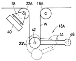
- the feeding-side tension operating device 18A includes a movable pulley 20A that is a feeding-side tension applying member.
- the fixed pulleys 12B, 14B, 16B in order from the side closer to the wire winding device 10B, the fixed pulleys 12B, 14B, 16B, the winding side tension.
- An operating device 18B and a fixed pulley 22B are provided, and the winding side tension operating device 18B includes a movable pulley 20B which is a winding side tension applying member.
- Each of the wire feeding / winding devices 10A and 10B includes bobbins 9A and 9B around which a wire W for cutting is wound, and bobbin driving motors 11A and 11B that rotationally drive the bobbins.
- the wire W fed from the bobbin 9A of the wire feeding device 10A is hung in the order of the fixed pulleys 12A, 14A, 16A, the movable pulley 20A of the tension operating device 18A, and the fixed pulley 22A, and further guide rollers 24A, 24B, 26B, After being wound many times on the outside of 26A, the fixed pulley 22B, the movable pulley 20B of the tension operating device 18B, and the fixed pulleys 16B, 14B, and 12B are hung in this order and wound around the bobbin 9B of the wire winding device 10B.
- the wire saw also includes a roller drive motor 25, which is connected to the rotation shaft of a specific guide roller (guide roller 26A in the illustrated example) among the guide rollers 24A, 24B, 26B, and 26A.
- the shaft is driven to rotate.
- the rotation driving direction of the bobbins 9A and 9B by the bobbin driving motors 11A and 11B and the rotation driving direction of the guide roller 26A by the roller driving motor 25 are switched between forward and reverse.
- the driving state of the wire W is switched between a state where the wire W is drawn out from the bobbin 9A and wound around the bobbin 9B, and a state where the wire W is drawn out from the bobbin 9B and wound around the bobbin 9A.
- a number of wires W are stretched between the guide rollers 24A and 24B among the four guide rollers, and these are stretched in the longitudinal direction (axial direction). It is driven back and forth.
- the number of the guide rollers can be freely set in a range of two or more regardless of the specific number.
- a work feeding device 30 for moving a cylindrical work (for example, a semiconductor ingot) 28 is provided above the wire W stretched between the guide rollers 24A and 24B.
- the workpiece feeding device 30 includes a workpiece holding unit 32 that holds the workpiece 28 and a workpiece feeding motor 34.
- the direction in which the work holding unit 32 holds the work 28 is set to a direction in which a target crystal orientation is obtained based on the crystal axis.
- the work feed motor 34 moves up and down (that is, cuts and feeds) the work holding part 32 and the work 28 together in cooperation with a ball screw (not shown).
- the work feed motor 34 according to this embodiment is constituted by a servo motor and also serves as a feed position detecting means for detecting the cutting feed position of the work 28.
- Slurry supply devices 36A and 36B are provided at positions on the left and right sides of the work 28 above the wire W stretched between the guide rollers 24A and 24B. These slurry supply devices 36 ⁇ / b> A and 36 ⁇ / b> B simultaneously supply a working fluid (slurry) mixed with abrasive grains to each wire W driven at high speed, and attach it to the surface of the wire W.
- this wire saw a large number of wires W stretched between the guide rollers 24A and 24B are simultaneously driven in the longitudinal direction at a high speed, and the machining fluid is supplied to the wires W from the slurry supply devices 36A and 36B.
- the machining fluid is supplied to the wires W from the slurry supply devices 36A and 36B.
- the movable pulley 20A is arranged between the fixed pulleys 16A and 22A, and the pulleys 16A, 20A and 22A are arranged so that the wire length is changed by the vertical movement of the movable pulley 20A. Specifically, the wire length increases when the movable pulley 20A descends, and the wire length decreases when the movable pulley 20A rises.
- the tension operating device 18A includes a support member 38 that rotatably supports the fixed pulley 22A, and a tension detector 40 attached to the support member 38.
- the tension detector 40 detects the load applied to the support member 38 and, consequently, the tension of the wire W.
- a load cell or a combination of a differential transformer and a spring can be used as the tension detector 40.
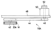
- the movable pulley 20A is attached to the tip of the lever 44 so as to be rotatable about a rotating shaft 42 orthogonal to the axial direction of the wire W.
- a rotation center shaft 46 is fixed to the base end of the lever 44, and the rotation center shaft 46 is supported by a fixed side plate 48.
- a swing cylinder 50 is fixed to the fixed side plate 48, and the rotation center shaft 46 is connected to the swing cylinder 50.
- the swing cylinder 50 rotates the lever 44 and the movable pulley 20A integrally with the rotation center shaft 46 and presses the movable pulley 20A against the wire W.
- a tension is applied, and the tension is changed by increasing or decreasing the pressing force.
- An encoder 52 is connected to the rotation center shaft 46.
- the encoder 52 detects the rotation angle position of the rotation center shaft 46, in other words, the position of the movable pulley 20A.
- This wire saw is provided with a controller 60 as shown in FIG.
- the controller 60 has a function as a tension control device, and includes a tension adjusting unit 62, a speed adjusting unit 64, and a target tension setting unit 66.
- the tension adjusting unit 62 controls the swing cylinder 50 so that the wire tension detected by the tension detector 40 on each of the wire feeding side and the wire winding side is maintained at the target tension T set by the target tension setting unit 66.
- An electric signal is output to the pneumatic servo circuit 54 to be driven to adjust the driving force of the swing cylinder 50 and the wire tension. Specifically, for example, when the detected tension on the wire feeding / winding device 10A side is higher than the target tension T, the driving force of the swing cylinder 50 is reduced and the lever connected to the swing cylinder 50 is reduced. By rotating 44 upward, the force with which the movable pulley 20A supported by the lever 44 is pressed against the wire W is lowered.
- the speed adjusting unit 64 includes a forward drive cutting process, a first switching process, a backward drive cutting process, and a second switching process, which will be described in detail later, as a process for cutting the workpiece 28 while driving the wire W.
- the direction and driving speed of bobbin driving by the bobbin driving motors 11A and 11B are adjusted so as to be repeatedly executed in this order.
- the workpiece 28 is cut while the wire W is fed from the wire feeding device 10A and wound on the wire winding device 10B.
- the workpiece W is cut while the wire W taken up by the wire take-up device 10B is taken out from the wire take-up device 10B and taken up by the wire take-up device 10A. It is advanced.
- the driving speed of the wire W is decelerated after the forward driving cutting step, and the driving direction of the wire is accelerated after the driving direction is reversed. As a result, the process proceeds to the next backward drive cutting step.
- the drive speed of the wire is decelerated after the reverse drive cutting step, and the drive direction of the wire is accelerated after the direction of the drive is reversed, thereby the next forward drive. Move to cutting process.
- the position of the movable pulleys 20A and 20B detected by the encoder 52 is set in advance as a reference position (here, the lever 44 is horizontal as shown by the solid line in FIG. 2). It also has a function of finely adjusting the rotational speeds of the bobbins 9A and 9B by outputting control signals to the bobbin drive motors 11A and 11B so as to approach the position). For example, in the state where the wire W is fed out from the bobbin 9A and wound around the bobbin 9B, when it is detected that the movable pulley 20A on the feeding side is below the reference position, the movable pulley 20A is raised.
- the rotational speed of the bobbin 9A on the side serving as the wire feeding device is decreased and, conversely, when it is detected that the movable pulley 20A is located above the reference position, the movable pulley 20A is In order to lower, the rotational speed of the bobbin 9A on the side serving as the wire feeding device is increased.
- the bobbin 9B on the side serving as the wire winding device is lifted to raise the movable pulley 20B.
- the target tension setting unit 66 sets the target tension T of the wire W and inputs it to the tension adjustment unit 62 as described above.
- the target tension T is shown at the bottom of FIG. It has the characteristic to be changed. Specifically, it is as follows.
- the target tension setting unit 66 fixes the target tension T on the wire feeding device 10A side to the first target tension T1, and sets the target tension T on the wire winding device 10B side to the above-described target tension T.
- the second target tension T2 is fixed to be lower than the first target tension T1.
- the target tension setting unit 66 sets the target tension T on the wire winding device 10B side from the second target tension T2 to a third target tension T2 higher than the second target tension T2. Gradually increase to the target tension T3. Conversely, the target tension T on the wire feeding device 10A side is gradually lowered from the first target tension T1 to the fourth target tension T4 lower than the first target tension T1 and the third target tension T3. .
- the target tension setting unit 66 is configured to synchronize with the timing of deceleration and acceleration of the driving speed of the wire W as shown in the uppermost and lowermost stages of FIG. Rise and fall. Specifically, the target tension T on the wire winding device 10B side starts to increase almost simultaneously with the start of the deceleration of the wire drive speed, and reaches the third target tension T3 (> T2) almost simultaneously with the completion of the deceleration. To reach. Next, the target tension T on the wire feeding device 10A side starts to decrease after completion of deceleration of the wire drive speed (substantially simultaneously with the completion), and the fourth target tension almost simultaneously with completion of acceleration toward the reverse side. T4 ( ⁇ T1) is reached.
- the target tension setting unit 66 fixes the target tension T on the wire winding device 10B side to the third target tension T3, and sets the target tension T on the wire feeding device 10A side.
- the fourth target tension T4 is fixed.
- Second switching step In this step, the target tension setting unit 66 gradually increases the target tension T on the wire feeding device 10A side from the fourth target tension T4 to the first target tension T1. Conversely, the target tension T on the wire winding device 10B side is gradually lowered from the third target tension T3 to the second target tension T2.
- the target tension setting unit 66 is configured to reduce and accelerate the driving speed of the wire W as shown in the uppermost and lowermost stages of FIG. 5 as in the first switching step.
- the target tension T is increased and decreased in synchronization with the timing. Specifically, the target tension T on the wire feeding device 10A side starts to increase almost simultaneously with the start of deceleration of the wire drive speed, and returns to the first target tension T1 (> T4) almost simultaneously with the completion of the deceleration. Let Next, the target tension T on the side of the wire winding device 10B begins to decrease after completion of deceleration of the wire driving speed (substantially simultaneously with the completion), and substantially simultaneously with completion of acceleration toward the reverse side. Return to tension T2 ( ⁇ T3).
- the first target tension T1 and the third target tension T3 are each set to 25 (N), and the second target tension T2 and the fourth target tension T4 are each 13 ( N).
- the transition speed of the target tension T in each switching step is set so that the transition substantially coincides with the end of deceleration of the wire drive speed in the switching step (that is, when the wire W stops).
- the bobbin 9A of the wire feeding device 10A is rotationally driven in the feeding direction, and the bobbin 9B of the wire winding device 10B is driven in the winding direction, so that the wire W is fed from the bobbin 9A. And wound on the bobbin 9B.
- the workpiece 28 is cut and fed together with the forward drive of the wire W, the workpiece 28 is cut.
- the target tension setting unit 66 sets the target tension T of the wire W on the wire feeding device 10A side to the first target tension T1 (for example, 25N), and the target tension T of the wire W on the wire winding device 10B side. Is set to the second target tension T2 (for example, 13N).
- the tension adjusting unit 62 determines that the detected tension of the tension detector 40 on the wire feeding device 10A side and the detected tension of the tension detector 40 on the wire winding device 10B side are the first target.
- the driving force of each oscillating cylinder 50 is adjusted so as to approach the tension T1 and the second target tension T2.
- the detection signal of the encoder 52 (that is, the position detection signal of the movable pulley 20A) provided in the tension operating device 18A is taken into the speed adjustment unit 64.
- the speed adjusting unit 64 compares the detection position of the movable pulley 20A with a preset reference position. If the former is higher than the latter, the speed adjusting unit 64 is a bobbin that is a wire feeding bobbin to lower the movable pulley 20A. Increase the rotational speed of 9A. Conversely, when the former is lower than the latter, the rotational speed of the bobbin 9A, which is a wire feeding bobbin, is decreased to raise the movable pulley 20A.
- the movable pulley 20A is held substantially at the reference position, and the margin for movement is ensured.
- the wire tension on the side of the wire feeding device 10A is kept substantially at the first target tension T1, thereby ensuring the wire tension necessary for good cutting of the workpiece 28 between the guide rollers 24A and 24B.
- the wire tension on the side of the wire winding device 10B is substantially suppressed to the second target tension T2
- the biting of the wire W in the bobbin 9B of the wire winding device 10B is alleviated and added to the device 10B. Mechanical burden is reduced.
- First switching step After the forward drive cutting step is executed for a preset first wire length (for example, 300 m), the process proceeds to the first switching step.
- the drive of the wire W is gradually decelerated (forward deceleration). Then, when the speed becomes zero, that is, when the forward deceleration is finished, this time, the direction of driving of the wire W is reversed and gradually accelerated (reverse acceleration), and the process proceeds to the next reverse drive cutting step. That is, the drive of the wire W is gradually switched from the forward drive to the backward drive.
- the target tension setting unit 66 changes the target tension as shown in the lowermost stage of FIG. Specifically, almost simultaneously with the deceleration of the wire W, the target tension T on the wire winding device 10B side starts to increase from the second target tension T2 so far, and the third target is reached by the end of the forward deceleration. Tension T4 (25N in this embodiment) is reached. Further, the target tension T on the wire feeding device 10A side starts to decrease from the first target tension T1 until the end of the forward deceleration, and the fourth target tension T4 (for example, 13N) until the reverse acceleration is completed. To reach.
- the actual wire tension also increases or decreases, and when the backward drive is started, the wire tension on the wire winding device 10B side is increased to about 25N, and further, when the backward acceleration is finished.
- the wire tension on the wire feeding device 10A side is lowered to approximately 13N.
- Reverse drive cutting step In this step, the bobbin 9B of the wire winding device 10B is rotationally driven in the feeding direction, and the bobbin 9A of the wire feeding device 10A is driven in the winding direction, whereby the wire W is fed from the bobbin 9B. And wound around the bobbin 9A.
- the tension control is already complete with the control of bringing the wire tension on the wire winding device 10B side closer to the third target tension T3 and the wire tension on the wire feeding device 10A side approaching the fourth target tension T4. Because of this transition, the wire tension ( ⁇ 25N) necessary for good cutting of the workpiece 28 can be secured between the guide rollers 24A and 24B, as in the forward drive cutting step, and the winding side has been reached. By suppressing the wire tension on the side of the wire feeding device 10A ( ⁇ 13N), the burden on the strength of the device 10A can be reduced.
- Second switching step After the backward drive cutting step is performed for a second wire length (for example, 100 m) shorter than the first wire length, the process proceeds to the second switching step. Also in this step, first, the drive of the wire W is gradually decelerated (reverse deceleration), and when the speed becomes zero, that is, when the reverse deceleration is completed, the direction of the drive of the wire W is reversed and gradually. Accelerated (forward acceleration), and proceeds to the forward drive cutting step. That is, the drive of the wire W is gradually switched from the backward drive to the forward drive.
- a second wire length for example, 100 m
- the target tension setting unit 66 changes the target tension as shown in the lowermost stage of FIG. Specifically, almost simultaneously with the deceleration of the wire W, the target tension T on the side of the wire feeding device 10A starts to increase from the fourth target tension T4 so far, and almost simultaneously with the end of the deceleration, the wire feeding device 10A.
- the target tension T on the side is returned to the first target tension T1.
- the target tension T on the wire take-up device 10B side starts to decrease from the third target tension T3 until then, and the target on the wire take-up device 10B side is finished until the forward acceleration is finished.
- the tension T is returned to the second target tension T2.
- the tension for tension adjustment provided on the wire feeding device 10A side and the wire winding device 10B side, respectively, while adopting the reciprocating driving method in which the wire W is repeatedly moved forward and backward.
- the wire tension on the winding side is reduced while securing the wire tension required for stable cutting, and the bobbin on the winding side (bobbin 9B when moving forward, The strength burden on the bobbin 9A) can be reduced.
- the tension is switched between the first switching process and the second switching process for reversing the wire, it is possible to prevent the occurrence of loss time due to the switching of the tension.
- the drop in the wire target tension on the wire feeding device 10A side in the first switching step and the drop in the wire target tension on the wire winding device 10B side in the second switching step are the wire drive speeds, respectively. Therefore, the processing accuracy of the workpiece 28 can be prevented from being lowered due to the decrease in the target tension.
- the wire target tension drop on the wire feeding device 10A side in the first switching step and the wire on the wire winding device 10B side in the second switching step are started almost simultaneously with the start of deceleration of the wire drive speed, in other words, when the wire target tension drop is performed within the deceleration periods A1 and A2 shown in FIG.
- the wire target tension drop is performed within the deceleration periods A1 and A2 shown in FIG.
- the portion of the wire W whose tension has actually decreased due to the decrease in the target tension is wound around the guide rollers 24A, 24B, 26B, and 26A shown in FIG.
- the target tension on the low tension side starts increasing simultaneously with the start of the deceleration periods A1 and A2 during each switching step, and immediately after the end of the deceleration periods A1 and A2.
- Each of the target tensions starts decreasing, but a time difference may be given to the timing.
- the target tension may start to increase after the start of the deceleration periods A1 and A2, or after the end of the deceleration periods A1 and A2. The target tension may be lowered.
- the target tension is switched in synchronism with each switching step, and the target tension is lowered after the end of the deceleration of the wire drive speed (including at the same time as the end of the wire driving speed). It may be completed by the end of the acceleration of the driving speed.
- both the first switching process and the second switching process are used as the tension switching period, but either one of the switching processes is used as one tension switching period, and the other The other tension switching period may protrude from the switching step. Even in this form, it is possible to increase the work efficiency by eliminating the loss time due to one of the tension switching periods.
- the present invention can take the following aspects, for example.
- the first target tension T1 and the third target tension T3 may not be equal, and similarly, the second target tension T2 and the fourth target tension T4 may not be equal.
- These target tensions can be appropriately set within a range that satisfies the condition that the target tensions T2 and T4 are lower than the target tensions T1 and T3, respectively.
- the specific configuration of tension control is not particularly limited.
- the fine adjustment of the wire driving speed by the speed adjusting unit 64 can be omitted.
- control may be performed so as to temporarily increase the wire tension (the tension of the wire portion contributing to the cutting of the work 28) at the beginning of the work cutting.
- the movable pulleys 20A and 20B may be linearly displaced by a feed screw mechanism, a rack and pinion mechanism or the like while being guided by a rail or the like.
- the means for swinging the lever 44 is not limited to the swing cylinder 50, and for example, a servo motor may be used.
- the present invention can effectively reduce the loss time due to the adjustment of the wire tension when reversing the direction of driving of the wire in the wire saw, and prevent a decrease in workpiece machining accuracy due to the tension adjustment.
- Provide technology that can.
- the present invention uses a wire saw in which a cutting wire fed from a wire feeding device is wound around a plurality of guide rollers and wound around the wire winding device, and is arranged between the guide rollers.
- a method of cutting and feeding a workpiece by moving the workpiece relative to these wires while driving a plurality of wires in the axial direction.
- the wire is fed out from the wire feeding device, the wire is wound up by the wire winding device, and the feeding side tension applying member is pressed against the wire fed out from the wire feeding device.
- the tension of the wire is adjusted to approach the first target tension, and the winding side tension applying member is pressed against the tension of the wire wound by the wire winding device, thereby bringing the wire into the first target tension.
- a forward drive cutting step of cutting the workpiece while adjusting the second target tension to be lower than the tension, and the wire wound by the wire winding device is reversed from the wire winding device.
- a wire that is unwound and wound by the wire unwinder and is unwound from the wire winder By adjusting the tension of the wire so as to approach a third target tension higher than the second target tension by pressing the winding side tension applying member, and the wire wound by the wire feeding device
- the workpiece is cut while adjusting the tension of the wire to be close to the first target tension and the fourth target tension lower than the third target tension by pressing the feeding side tension applying member.
- the drive speed of the wire is decelerated, the direction of the drive is reversed, and then the drive speed of the wire is accelerated before
- a second switching step shifts to forward drive cutting process, the forward drive cutting step, the first switching step, the reverse drive cutting step, and the second switching step is performed repeatedly in this order.
- the first switching step the winding so as to increase the target tension of the wire on the wire winding device side from the second target tension to the third target tension during the deceleration of the wire driving speed.
- the tension of the wire is adjusted by the side tension applying member, and the target tension of the wire on the wire feeding device side is changed from the first target tension to the fourth target tension after the deceleration of the wire driving speed is completed.
- the tension of the wire is adjusted by the feeding side tension applying member that is lowered.
- the wire tension is switched using the time required for the deceleration of the wire and the subsequent acceleration in the first switching step. Therefore, there is no loss time generated due to the tension switching.
- the adjustment for lowering the wire tension from the first target tension to the fourth target tension is performed after the completion of the deceleration of the wire, the wire portion whose tension is reduced by the adjustment enters the cutting process region between the guide rollers. Is prevented, and the deterioration of the machining accuracy of the workpiece due to this is prevented.
- the workpiece cutting method according to the present invention is not limited to the transition of the target tension in the first switching step, or in addition to the transition of the target tension in the first switching step, during the second switching step.
- the wire tension is adjusted by the winding-side tension applying member while lowering the target tension of the wire on the wire winding device side from the third target tension to the second target tension, and the wire The wire tension may be adjusted by the feeding-side tension applying member while raising the target tension of the wire on the feeding device side from the fourth target tension to the first target tension.
- tension adjustment is performed so as to increase the wire target tension from the fourth target tension to the first target tension during the deceleration of the driving speed of the wire, and the wire After the completion of deceleration of the driving speed, control is performed to lower the target tension of the wire from the third target tension to the second target tension, so that the wire portion whose tension is reduced by the adjustment is cut between the guide rollers. It is possible to prevent the workpiece from entering the machining area, and to prevent the workpiece machining accuracy from being lowered due to this.
- the operations for adjusting the tension of the wire in each of the steps include an operation of detecting the actual tension of the wire, and applying each tension to a predetermined portion of the wire so that the detected tension approaches a target tension. It is preferable to include an operation of pressing a member.
- the present invention also provides a wire saw for simultaneously cutting a workpiece at a plurality of locations using a cutting wire.
- the wire saw includes a plurality of guide rollers that are arranged so that rotation center axes thereof are parallel to each other and around which the wire is wound, and a wire feeding device that feeds the wire to the guide rollers.
- a wire winding device for winding the wire from the guide roller, and a plurality of wires stretched between specific guide rollers of the guide rollers and a workpiece are moved relative to the wire.
- a cutting and feeding device that cuts and feeds the workpiece and feeds the wire from the wire feeding device, and advances the cutting of the workpiece while winding the wire by the wire winding device
- the drive cutting process and the wire wound up by the wire winding device are fed out from the wire winding device in reverse.
- a backward drive cutting step for cutting the workpiece, and after the forward drive cutting step, the drive speed of the wire is reduced and the direction of the drive is reversed before the wire
- the second switching step of accelerating the speed and shifting to the forward drive cutting step is repeated in the order of the forward drive cutting step, the first switching step, the reverse drive cutting step, and the second switching step.
- a wire drive control device for controlling the operation of the wire feeding device and the wire winding device to perform, and a region between the wire feeding device and each guide roller. And an area between the wire take-up device and each of the guide rollers, including a feeding-side tension applying member that is pressed against the wire, and changing the pressing force to change the tension of the wire.
- a winding-side tension applying device that includes a winding-side tension applying member that is pressed against the wire, and changes the tension of the wire by changing the pressing force, and in the forward drive cutting process, the wire is fed from the wire feeding device.
- the tension of the wire to be brought closer to the first target tension, and the tension of the wire wound by the wire winding device is brought closer to the second target tension lower than the first target tension.
- the tension of the wire fed from the wire winding device is brought close to a third target tension higher than the second target tension.
- the tension control device that operates each of the tension manipulating devices so that the tension of the wire wound by the wire feeding device is closer to the fourth target tension lower than the first target tension and the third target tension. With. In the first switching step, the tension control device raises the target tension of the wire on the wire winding device side from the second target tension to the third target tension during the deceleration of the driving speed of the wire.
- Each tension operating device is actuated to adjust the tension of the wire.
- the tension control device replaces the transition of the target tension in the first switching step, or in addition to the transition of the target tension in the first switching step.
- the tension control device may be operated so as to adjust the tension of the wire while increasing the target tension of the wire from the fourth target tension to the first target tension.
- the loss time due to the switching of the tension of the wire can be eliminated, and also in the second switching step, the wire target tension is changed to the fourth target tension during the deceleration of the driving speed of the wire.
- the tension is adjusted so as to increase from the first target tension to the first target tension, and the wire target tension is decreased from the third target tension to the second target tension after the completion of deceleration of the driving speed of the wire.
- the wire portion whose tension has been reduced by the adjustment is prevented from entering the cutting region between the guide rollers, thereby preventing a decrease in workpiece processing accuracy due to this.
- the tension control device includes a tension detector that detects the tension of the wire in the region from the wire feeding device to the guide roller and the region from the guide roller to the wire winding device, What includes a target tension setting unit that sets a target tension, and a tension adjustment unit that operates the tension operating device to bring the tension detected in each region close to the target tension set by the target tension setting unit, Is preferred.
- the device for manipulating the tension of the wire by pressing the tension applying member against the wire is effectively utilized, and the loss time can be reduced while effectively reducing only the tension of the wire on the winding side. It is possible to cut the workpiece with less efficient operation and to prevent a decrease in the machining accuracy of the workpiece due to the tension adjustment.
Landscapes
- Engineering & Computer Science (AREA)
- Mechanical Engineering (AREA)
- Finish Polishing, Edge Sharpening, And Grinding By Specific Grinding Devices (AREA)
- Processing Of Stones Or Stones Resemblance Materials (AREA)
- Mechanical Treatment Of Semiconductor (AREA)
Abstract
Priority Applications (6)
| Application Number | Priority Date | Filing Date | Title |
|---|---|---|---|
| CN201080063198.8A CN102791426B (zh) | 2010-02-08 | 2010-02-08 | 用线锯切断工件的切断方法以及线锯 |
| KR1020127023013A KR101625709B1 (ko) | 2010-02-08 | 2010-02-08 | 실톱을 이용한 소재의 절단방법 및 실톱 |
| PCT/JP2010/000751 WO2011096018A1 (fr) | 2010-02-08 | 2010-02-08 | Procédé de coupe d'une pièce à travailler au moyen d'une scie à fil, et scie à fil |
| EP10845156.8A EP2535143B1 (fr) | 2010-02-08 | 2010-02-08 | Procédé de coupe d'une pièce à travailler au moyen d'une scie à fil, et scie à fil |
| SG2012057220A SG183130A1 (en) | 2010-02-08 | 2010-02-08 | Method of cutting workpiece with wire saw, and wire saw |
| US13/576,738 US8991381B2 (en) | 2010-02-08 | 2010-02-08 | Method of cutting workpiece with wire saw, and wire saw |
Applications Claiming Priority (1)
| Application Number | Priority Date | Filing Date | Title |
|---|---|---|---|
| PCT/JP2010/000751 WO2011096018A1 (fr) | 2010-02-08 | 2010-02-08 | Procédé de coupe d'une pièce à travailler au moyen d'une scie à fil, et scie à fil |
Publications (1)
| Publication Number | Publication Date |
|---|---|
| WO2011096018A1 true WO2011096018A1 (fr) | 2011-08-11 |
Family
ID=44355047
Family Applications (1)
| Application Number | Title | Priority Date | Filing Date |
|---|---|---|---|
| PCT/JP2010/000751 Ceased WO2011096018A1 (fr) | 2010-02-08 | 2010-02-08 | Procédé de coupe d'une pièce à travailler au moyen d'une scie à fil, et scie à fil |
Country Status (6)
| Country | Link |
|---|---|
| US (1) | US8991381B2 (fr) |
| EP (1) | EP2535143B1 (fr) |
| KR (1) | KR101625709B1 (fr) |
| CN (1) | CN102791426B (fr) |
| SG (1) | SG183130A1 (fr) |
| WO (1) | WO2011096018A1 (fr) |
Cited By (2)
| Publication number | Priority date | Publication date | Assignee | Title |
|---|---|---|---|---|
| CN102350742A (zh) * | 2011-09-30 | 2012-02-15 | 大连连城数控机器股份有限公司 | 四辊直驱式金刚石线数控切片机 |
| CN116690817A (zh) * | 2023-04-21 | 2023-09-05 | 华侨大学 | 一种多线切割机的排线自动纠偏装置及方法 |
Families Citing this family (24)
| Publication number | Priority date | Publication date | Assignee | Title |
|---|---|---|---|---|
| JP5515593B2 (ja) * | 2009-10-07 | 2014-06-11 | 株式会社Sumco | ワイヤーソーによるシリコンインゴットの切断方法およびワイヤーソー |
| DE102012221904B4 (de) | 2012-11-29 | 2018-05-30 | Siltronic Ag | Verfahren zur Wiederaufnahme des Drahtsägeprozesses eines Werkstückes nach einer unplanmäßigen Unterbrechung |
| TWI682820B (zh) * | 2012-12-04 | 2020-01-21 | 瑞士商精密表面加工解決方案有限公司 | 線鋸及切割方法 |
| JP6173149B2 (ja) * | 2013-09-26 | 2017-08-02 | 日特エンジニアリング株式会社 | ワイヤソー及びワイヤによるワークの切断方法 |
| JP2015155119A (ja) * | 2014-02-20 | 2015-08-27 | 株式会社タカトリ | ワイヤソー及び切断加工方法 |
| DE102014208187B4 (de) * | 2014-04-30 | 2023-07-06 | Siltronic Ag | Verfahren zum gleichzeitigen Trennen einer Vielzahl von Scheiben mit besonders gleichmäßiger Dicke von einem Werkstück |
| CN104493982A (zh) * | 2014-12-30 | 2015-04-08 | 南京铭品机械制造有限公司 | 一种数控丝锯加工机 |
| JP6402700B2 (ja) * | 2015-10-20 | 2018-10-10 | 信越半導体株式会社 | ワークの切断方法及びワイヤソー |
| WO2018012313A1 (fr) * | 2016-07-13 | 2018-01-18 | 信越半導体株式会社 | Dispositif de scie à fil et procédé de découpe de pièce de fabrication |
| US10973161B2 (en) * | 2017-01-13 | 2021-04-06 | Raytheon Company | Electronic component removal device |
| JP6693460B2 (ja) * | 2017-04-04 | 2020-05-13 | 信越半導体株式会社 | ワークの切断方法 |
| TWI713832B (zh) * | 2017-04-28 | 2020-12-21 | 友達晶材股份有限公司 | 晶圓切片機及其收放線裝置與晶圓切片的方法 |
| CN107599194A (zh) * | 2017-08-24 | 2018-01-19 | 天津市环欧半导体材料技术有限公司 | 一种硅片线切方法 |
| CN108217312A (zh) * | 2018-02-13 | 2018-06-29 | 福建富易天龙智能科技有限公司 | 一种用于石膏绷带多线切割的上线方法和装置 |
| EP3587013A1 (fr) * | 2018-06-21 | 2020-01-01 | Meyer Burger AG | Scie à fil et méthode pour déterminer une caractéristique de mouvemnt d'une poulie de renvoi de fil d'une scie à fil |
| CN108942603B (zh) * | 2018-08-28 | 2019-08-23 | 三星智能科技盐城有限公司 | 一种数控金刚石砂线切割机床 |
| DE102019207719A1 (de) * | 2019-05-27 | 2020-12-03 | Siltronic Ag | Verfahren zum Abtrennen einer Vielzahl von Scheiben von Werkstücken während einer Anzahl von Abtrennvorgängen mittels einer Drahtsäge und Halbleiterscheibe aus einkristallinem Silizium |
| JP7500216B2 (ja) * | 2020-02-19 | 2024-06-17 | コマツNtc株式会社 | ワイヤソー |
| WO2022038634A1 (fr) * | 2020-08-16 | 2022-02-24 | Srinivasan Viswesh | Machine de découpe par fil à cnc améliorée |
| CN114737302A (zh) * | 2022-03-22 | 2022-07-12 | 浙江理工大学 | 一种三维间隔织机经线张力调整机构 |
| CN115990955B (zh) * | 2022-12-24 | 2025-08-01 | 西安奕斯伟材料科技股份有限公司 | 用于线切割硅棒的装置、设备、硅片及其制造方法 |
| CN116787624A (zh) * | 2023-07-05 | 2023-09-22 | 贝加莱工业自动化(中国)有限公司 | 多线切割机 |
| CN119036658B (zh) * | 2024-08-22 | 2025-05-06 | 扬州伟业创新科技有限公司 | 一种具有断线报警功能的硅片切割装置 |
| CN119347981B (zh) * | 2024-12-25 | 2025-04-04 | 泉州华大超硬工具科技有限公司 | 一种双排线式切割组件及其切割方法 |
Citations (3)
| Publication number | Priority date | Publication date | Assignee | Title |
|---|---|---|---|---|
| JPH0475862A (ja) * | 1990-07-18 | 1992-03-10 | Otaru Seisakusho:Kk | マルチワイヤ式切断装置 |
| JP2002254287A (ja) * | 2001-02-27 | 2002-09-10 | Nippei Toyama Corp | ワイヤソーのワイヤ送り方法及び送り装置 |
| JP2007276054A (ja) | 2006-04-06 | 2007-10-25 | Toyo Advanced Technologies Co Ltd | ワイヤソーによるワークの切断方法及びワイヤソー |
Family Cites Families (16)
| Publication number | Priority date | Publication date | Assignee | Title |
|---|---|---|---|---|
| US4655191A (en) * | 1985-03-08 | 1987-04-07 | Motorola, Inc. | Wire saw machine |
| JP2673544B2 (ja) * | 1988-06-14 | 1997-11-05 | 株式会社日平トヤマ | 脆性材料の切断方法 |
| JP2870452B2 (ja) * | 1995-05-31 | 1999-03-17 | 信越半導体株式会社 | ワイヤソー |
| US5564409A (en) * | 1995-06-06 | 1996-10-15 | Corning Incorporated | Apparatus and method for wire cutting glass-ceramic wafers |
| JP3107143B2 (ja) * | 1995-07-14 | 2000-11-06 | 株式会社東京精密 | ワイヤソーのワイヤトラバース装置 |
| CH691292A5 (fr) * | 1995-10-03 | 2001-06-29 | Hct Shaping Systems Sa | Dispositif de sciage par fil équipé d'un système de gestion de fil permettant l'utilisation de bobines de fil de très grande longueur. |
| US5944007A (en) * | 1996-02-08 | 1999-08-31 | Tokyo Rope Mfg. Co., Ltd. | Wire type slicing machine and method |
| MY113652A (en) * | 1996-04-27 | 2002-04-30 | Nippei Toyama Corp | Wire saw and work slicing method |
| JP2907182B2 (ja) * | 1997-04-09 | 1999-06-21 | 住友電気工業株式会社 | ダンサローラ装置 |
| JP2000061803A (ja) * | 1998-08-27 | 2000-02-29 | Hitachi Cable Ltd | ソーワイヤ集合体及びそれを用いた切断方法及びその装置 |
| US6945242B2 (en) * | 2001-10-17 | 2005-09-20 | Neomax Co., Ltd. | Cutting method using wire saw, wire saw device, and method of manufacturing rare-earth magnet |
| JP4083152B2 (ja) * | 2004-07-29 | 2008-04-30 | 日本碍子株式会社 | ワイヤーソー装置 |
| JP4820108B2 (ja) * | 2005-04-25 | 2011-11-24 | コマツNtc株式会社 | 半導体ウエーハの製造方法およびワークのスライス方法ならびにそれらに用いられるワイヤソー |
| WO2008001816A1 (fr) * | 2006-06-30 | 2008-01-03 | Nagasaki University | Procédé et dispositif de coupe |
| JP4816511B2 (ja) | 2007-03-06 | 2011-11-16 | 信越半導体株式会社 | 切断方法およびワイヤソー装置 |
| CN101301734B (zh) * | 2008-06-25 | 2010-12-08 | 周文敏 | 微机控制多线切割机 |
-
2010
- 2010-02-08 KR KR1020127023013A patent/KR101625709B1/ko active Active
- 2010-02-08 US US13/576,738 patent/US8991381B2/en active Active
- 2010-02-08 SG SG2012057220A patent/SG183130A1/en unknown
- 2010-02-08 EP EP10845156.8A patent/EP2535143B1/fr active Active
- 2010-02-08 WO PCT/JP2010/000751 patent/WO2011096018A1/fr not_active Ceased
- 2010-02-08 CN CN201080063198.8A patent/CN102791426B/zh active Active
Patent Citations (3)
| Publication number | Priority date | Publication date | Assignee | Title |
|---|---|---|---|---|
| JPH0475862A (ja) * | 1990-07-18 | 1992-03-10 | Otaru Seisakusho:Kk | マルチワイヤ式切断装置 |
| JP2002254287A (ja) * | 2001-02-27 | 2002-09-10 | Nippei Toyama Corp | ワイヤソーのワイヤ送り方法及び送り装置 |
| JP2007276054A (ja) | 2006-04-06 | 2007-10-25 | Toyo Advanced Technologies Co Ltd | ワイヤソーによるワークの切断方法及びワイヤソー |
Non-Patent Citations (1)
| Title |
|---|
| See also references of EP2535143A4 |
Cited By (3)
| Publication number | Priority date | Publication date | Assignee | Title |
|---|---|---|---|---|
| CN102350742A (zh) * | 2011-09-30 | 2012-02-15 | 大连连城数控机器股份有限公司 | 四辊直驱式金刚石线数控切片机 |
| CN116690817A (zh) * | 2023-04-21 | 2023-09-05 | 华侨大学 | 一种多线切割机的排线自动纠偏装置及方法 |
| CN116690817B (zh) * | 2023-04-21 | 2025-09-30 | 华侨大学 | 一种多线切割机的排线自动纠偏装置及方法 |
Also Published As
| Publication number | Publication date |
|---|---|
| CN102791426A (zh) | 2012-11-21 |
| EP2535143A1 (fr) | 2012-12-19 |
| KR101625709B1 (ko) | 2016-05-30 |
| US8991381B2 (en) | 2015-03-31 |
| KR20120130192A (ko) | 2012-11-29 |
| EP2535143A4 (fr) | 2017-04-12 |
| CN102791426B (zh) | 2014-12-10 |
| US20120298090A1 (en) | 2012-11-29 |
| SG183130A1 (en) | 2012-09-27 |
| EP2535143B1 (fr) | 2018-08-08 |
Similar Documents
| Publication | Publication Date | Title |
|---|---|---|
| KR101625709B1 (ko) | 실톱을 이용한 소재의 절단방법 및 실톱 | |
| KR101309131B1 (ko) | 와이어 소 | |
| EP2535144A1 (fr) | Scie à fil hélicoïdal | |
| CN109227976B (zh) | 一种自适应金刚石线锯切割设备 | |
| JP4512155B2 (ja) | ワイヤソーの運転方法及びワイヤソー | |
| CN202805447U (zh) | 钢丝式切断装置 | |
| JP2015155119A (ja) | ワイヤソー及び切断加工方法 | |
| US9969017B2 (en) | Wire saw apparatus and cut-machining method | |
| JP5502613B2 (ja) | ワーク切断方法及びワイヤソー | |
| CN112783095B (zh) | 机床的控制装置及机床的控制方法 | |
| JP3105431B2 (ja) | ワイヤソーにおけるワイヤ張力制御装置 | |
| JP2001232550A (ja) | ワイヤソーによる切断方法及びワイヤソー | |
| TWI488725B (zh) | Cutting method and wire sawing by wire saw | |
| JPH1170457A (ja) | 固定砥粒ワイヤソー及びその被加工物切断方法 | |
| JP2007276054A (ja) | ワイヤソーによるワークの切断方法及びワイヤソー | |
| JP5259248B2 (ja) | ワイヤソー | |
| JP5841742B2 (ja) | ワイヤソー装置及び切断加工方法 | |
| JP2010089173A (ja) | ワイヤソー | |
| JP5973778B2 (ja) | ワイヤソー装置及びワイヤ走行制御方法 | |
| JP4456714B2 (ja) | ワイヤソーを用いた切断方法 | |
| JP5784976B2 (ja) | ワイヤソー装置及び切断加工方法 | |
| JP4892278B2 (ja) | ワーク切断方法およびワイヤソー | |
| JPH1086141A (ja) | ワイヤソー | |
| JP5784999B2 (ja) | ワイヤソー装置及び切断加工方法 | |
| JP2010089197A (ja) | ワイヤ巻取り装置およびワイヤソー |
Legal Events
| Date | Code | Title | Description |
|---|---|---|---|
| WWE | Wipo information: entry into national phase |
Ref document number: 201080063198.8 Country of ref document: CN |
|
| 121 | Ep: the epo has been informed by wipo that ep was designated in this application |
Ref document number: 10845156 Country of ref document: EP Kind code of ref document: A1 |
|
| WWE | Wipo information: entry into national phase |
Ref document number: 13576738 Country of ref document: US |
|
| NENP | Non-entry into the national phase |
Ref country code: DE |
|
| WWE | Wipo information: entry into national phase |
Ref document number: 2010845156 Country of ref document: EP |
|
| ENP | Entry into the national phase |
Ref document number: 20127023013 Country of ref document: KR Kind code of ref document: A |
|
| WWE | Wipo information: entry into national phase |
Ref document number: 7663/CHENP/2012 Country of ref document: IN |
|
| NENP | Non-entry into the national phase |
Ref country code: JP |