WO2011105560A1 - プリプレグ積層ヘッド及びこれを備えたプリプレグ自動積層装置 - Google Patents
プリプレグ積層ヘッド及びこれを備えたプリプレグ自動積層装置 Download PDFInfo
- Publication number
- WO2011105560A1 WO2011105560A1 PCT/JP2011/054329 JP2011054329W WO2011105560A1 WO 2011105560 A1 WO2011105560 A1 WO 2011105560A1 JP 2011054329 W JP2011054329 W JP 2011054329W WO 2011105560 A1 WO2011105560 A1 WO 2011105560A1
- Authority
- WO
- WIPO (PCT)
- Prior art keywords
- prepreg
- prepreg sheet
- sheet
- head
- release paper
- Prior art date
- Legal status (The legal status is an assumption and is not a legal conclusion. Google has not performed a legal analysis and makes no representation as to the accuracy of the status listed.)
- Ceased
Links
Images


Classifications
-
- B—PERFORMING OPERATIONS; TRANSPORTING
- B29—WORKING OF PLASTICS; WORKING OF SUBSTANCES IN A PLASTIC STATE IN GENERAL
- B29C—SHAPING OR JOINING OF PLASTICS; SHAPING OF MATERIAL IN A PLASTIC STATE, NOT OTHERWISE PROVIDED FOR; AFTER-TREATMENT OF THE SHAPED PRODUCTS, e.g. REPAIRING
- B29C70/00—Shaping composites, i.e. plastics material comprising reinforcements, fillers or preformed parts, e.g. inserts
- B29C70/04—Shaping composites, i.e. plastics material comprising reinforcements, fillers or preformed parts, e.g. inserts comprising reinforcements only, e.g. self-reinforcing plastics
- B29C70/28—Shaping operations therefor
- B29C70/30—Shaping by lay-up, i.e. applying fibres, tape or broadsheet on a mould, former or core; Shaping by spray-up, i.e. spraying of fibres on a mould, former or core
- B29C70/38—Automated lay-up, e.g. using robots, laying filaments according to predetermined patterns
- B29C70/386—Automated tape laying [ATL]
- B29C70/388—Tape placement heads, e.g. component parts, details or accessories
-
- B—PERFORMING OPERATIONS; TRANSPORTING
- B29—WORKING OF PLASTICS; WORKING OF SUBSTANCES IN A PLASTIC STATE IN GENERAL
- B29C—SHAPING OR JOINING OF PLASTICS; SHAPING OF MATERIAL IN A PLASTIC STATE, NOT OTHERWISE PROVIDED FOR; AFTER-TREATMENT OF THE SHAPED PRODUCTS, e.g. REPAIRING
- B29C70/00—Shaping composites, i.e. plastics material comprising reinforcements, fillers or preformed parts, e.g. inserts
- B29C70/04—Shaping composites, i.e. plastics material comprising reinforcements, fillers or preformed parts, e.g. inserts comprising reinforcements only, e.g. self-reinforcing plastics
- B29C70/28—Shaping operations therefor
- B29C70/30—Shaping by lay-up, i.e. applying fibres, tape or broadsheet on a mould, former or core; Shaping by spray-up, i.e. spraying of fibres on a mould, former or core
- B29C70/38—Automated lay-up, e.g. using robots, laying filaments according to predetermined patterns
- B29C70/386—Automated tape laying [ATL]
-
- B—PERFORMING OPERATIONS; TRANSPORTING
- B29—WORKING OF PLASTICS; WORKING OF SUBSTANCES IN A PLASTIC STATE IN GENERAL
- B29K—INDEXING SCHEME ASSOCIATED WITH SUBCLASSES B29B, B29C OR B29D, RELATING TO MOULDING MATERIALS OR TO MATERIALS FOR MOULDS, REINFORCEMENTS, FILLERS OR PREFORMED PARTS, e.g. INSERTS
- B29K2105/00—Condition, form or state of moulded material or of the material to be shaped
- B29K2105/24—Condition, form or state of moulded material or of the material to be shaped crosslinked or vulcanised
- B29K2105/243—Partially cured
-
- Y—GENERAL TAGGING OF NEW TECHNOLOGICAL DEVELOPMENTS; GENERAL TAGGING OF CROSS-SECTIONAL TECHNOLOGIES SPANNING OVER SEVERAL SECTIONS OF THE IPC; TECHNICAL SUBJECTS COVERED BY FORMER USPC CROSS-REFERENCE ART COLLECTIONS [XRACs] AND DIGESTS
- Y10—TECHNICAL SUBJECTS COVERED BY FORMER USPC
- Y10T—TECHNICAL SUBJECTS COVERED BY FORMER US CLASSIFICATION
- Y10T156/00—Adhesive bonding and miscellaneous chemical manufacture
- Y10T156/17—Surface bonding means and/or assemblymeans with work feeding or handling means
Definitions
- the present invention relates to a prepreg lamination head for laminating a prepreg sheet in which a fiber sheet is impregnated with a resin to form a prepreg laminate, and a prepreg automatic laminating apparatus including the prepreg lamination head.
- the present application claims priority based on Japanese Patent Application No. 2010-041916 filed in Japan on February 26, 2010, the contents of which are incorporated herein by reference.
- a prepreg laminate (a composite material is formed) by laminating a plurality of prepreg sheets (FRP sheets) impregnated with resin in a fiber sheet (composite material is formed), and aircraft fuselage and main wings are manufactured using this prepreg laminate. (Forming) is done. Further, carbon fibers are frequently used because they have excellent characteristics such as light weight and high strength and high elasticity.
- the prepreg sheet is formed by aligning the fiber directions of a large number of fibers, and using an ultraviolet curable resin or a thermosetting resin as the impregnating resin, and semi-curing the resin in a state where the fiber sheet is impregnated ( Incompletely cured, uncured). For this reason, release paper is attached to one side (or both sides) of the prepreg sheet.
- the prepreg laminate is manufactured (formed) by removing release paper from the prepreg sheet and laminating a plurality of prepreg sheets integrally while crossing the fiber directions. That is, on the prepreg sheet (0 degree layer) with the fiber direction oriented in the 0 degree direction, the prepreg sheet (angle layer) with the fiber direction oriented in the 45 degree direction or 90 degree direction, for example, and further on the fiber direction
- the prepreg sheet (0 degree layer) is oriented in the 0 degree direction, and it is necessary while sequentially crossing the fiber direction to the workpiece (stacked body) integrally formed with the prepreg sheet laminated in advance in this way
- a prepreg laminate is manufactured by laminating a number of prepreg sheets.
- the prepreg automatic laminating apparatus A is provided on a gantry 1 and is laid between a laminating table 2 and a laminating table 2 which are movably mounted in one direction T1.
- the other portal-type support column 4 is configured to include an angle layer stacking head (prepreg stacking head) 6 that is rotatably supported around an axis extending in the vertical direction and disposed above the stacking table 2.
- the 0-degree layer stacking head 5 wraps and supports the supply roller 9 on which the prepreg sheet 8 with the release paper 7 attached on one side is wound, and the prepreg sheet 8 fed out from the supply roller 9.
- the supply roller 9, and the support roller 10 and without cutting the release paper 7, only the prepreg sheet 8 is set for each predetermined length (according to the size of the workpiece stacking target pieces).
- the die cutter 11 to be cut and the prepreg sheet 8 sent from the support roller 10 are guided in one direction T1 so as to be laminated on the workpiece on the lamination table 2, and the workpiece is pressed by pressing the prepreg sheet 8 from one side.
- a pressing roller 13 after the order to peel the Hanareshi 7 is configured to include a release paper collecting roller 14 for collecting the release paper 7 was peeled from the prepreg sheet 8.
- the angle layer laminating head 6 supports the supply roller 15 on which the prepreg sheet 8 with the release paper 7 attached on one side is wound, and the prepreg sheet 8 fed out from the supply roller 15 so as to be wound and supported. It is provided between the roller 16, the supply roller 15 and the support roller 16, and only the prepreg sheet 8 is cut every predetermined length without cutting the release paper 7 (according to the size of the workpiece stacking target piece).
- the laminating shoe 19 and the release paper 7 are collected between the ladle 8a and the scraper roller 18b.
- the laminating shoe 19 presses the prepreg sheet 8 sent from the support roller 16 and attaches it to the work on the laminating table 2.
- the release paper collecting roller 20 is provided.
- the release paper collecting roller 14 is rotated and the release paper 7 is pulled, and the prepreg sheet 8 is fed out from the supply roller 9. Further, while feeding from the supply roller 9, only the prepreg sheet 8 is cut into a predetermined length by the die cutter 11.
- the prepreg sheet 8 cut in this way is fed along the upper surface of the workpiece through the support roller 10 and is pressed (primary rolling) to the workpiece from the release paper 7 side by the front pressing roller 12. Thereby, the cut piece of the prepreg sheet 8 cut and divided by the die cutter 11 is overlapped and pasted on the stacking target pieces of the workpieces, and laminated integrally.
- the prepreg sheet 8 that has passed through the rear pressing roller 13 and is affixed to the workpiece is pressed again (secondary rolling), and the release paper 7 is peeled off from the prepreg sheet 8 to the release paper collection roller 14. It is wound up.
- the 0 degree layer prepreg sheet 8 with the fiber direction oriented in the length direction of the workpiece is a 0 degree layer lamination head. 5 is stacked on the workpiece.
- the workpiece W on which the prepreg sheet 8 is laminated by the 0-degree layer laminating head 5 is conveyed to the angle layer laminating head 6 side by the laminating table 2.
- the angle layer stacking head 6 is rotated, and the length direction of the workpiece W (the transport direction of the stacking table 2, one direction T1). ) With a predetermined crossing angle of 45 degrees or 90 degrees, for example, and the release paper collecting roller 20 is rotated in this state.
- the release paper 7 is pulled to feed out the prepreg sheet 8 from the supply roller 15, and only the prepreg sheet 8 is cut by the die cutter 17 every predetermined length.
- the prepreg sheet 8 is cut so as to be divided in a shape corresponding to the stacking target piece R1 of the workpiece W (for example, a diamond shape when a 45-degree layer is stacked on the workpiece W).
- the laminated shoe 19 presses the prepreg sheet 8 in the fiber direction.
- the cut piece S1 of the prepreg sheet 8 cut and divided by the die cutter 17 is overlapped and attached to the stacking target piece R1 of the workpiece W, and is laminated integrally.
- the release paper 7 is peeled off from the prepreg sheet 8 attached to the workpiece W, and taken up by the release paper collection roller 20.
- the angle layer prepreg sheet 8 crosses the length direction of the workpiece W (and hence the fiber direction T1 of the 0-degree layer prepreg sheet 8) with the angle direction of the fiber layer T2. Is laminated.
- the prepreg laminate is manufactured by sequentially laminating the prepreg sheets 8 while intersecting the fiber directions T1 and T2 by the 0 degree layer laminating head 5 and the angle layer laminating head 6.
- the laminating shoes 19 of the angle layer laminating head 6 are formed in a single rod shape. For this reason, when the lamination shoe 19 is moved forward and backward in the fiber direction T2 of the prepreg sheet 8 and the cut piece S1 of the prepreg sheet 8 is attached to the lamination target piece R1 of the workpiece W and laminated, as shown in FIG.
- the cut piece S2 to be attached next is also pressed. Moreover, the large area
- the release paper 7 of the cutting piece S2 is partially peeled off from the prepreg sheet 8, and floating or twisting occurs, which is a coverable state. Become.
- the release paper collecting roller 20 is rotated to pull the release paper 7 and the next cut piece S2 is placed on the next stacking target piece R2 of the workpiece W, the release paper of the cut piece S2 is placed. Since 7 is in a coverable state, there is a problem that the cutting piece S2 cannot be accurately positioned and arranged at a predetermined position.
- the bar-shaped laminated shoe 19 is disposed in the region of the lamination target piece R1 of the workpiece W, and the laminated shoe 19 is moved forward and backward so as not to press the next cutting piece S2, thereby partially cutting the cutting piece S1 of the prepreg sheet 8.
- the prepreg sheet 8 is laminated with the 0-degree layer laminating head 5
- the prepreg sheet 8 of the non-pressed angle layer is simultaneously pressed and pasted on the workpiece W.
- the area that is not pressed by the angle layer stacking head 6 has, for example, approximately the same area as the area M, that is, the larger area remains as the crossing angle becomes smaller. Simultaneously with the lamination of the prepreg sheet 8 by the 0-degree layer laminating head 5, it is difficult to completely (preferably) paste the non-pressed area of the angle layer, and it is impossible to ensure the quality of the product. End up.
- the present invention makes it possible to press only a cutting piece of a prepreg sheet to be laminated on a lamination target piece of a laminated body (work) with a lamination shoe, and accurately place the cutting piece at a predetermined position. It is an object of the present invention to provide a prepreg laminating head that enables positioning, and a prepreg automatic laminating apparatus including the prepreg laminating head.
- the present invention provides the following means.
- a prepreg lamination head is used when a prepreg laminate is formed by laminating a plurality of prepreg sheets in which a fiber sheet is impregnated with a resin, and a direction intersecting the length direction of the prepreg laminate.
- a prepreg laminating head for laminating the prepreg sheet with the fiber direction facing to the prepreg sheet, the release paper is attached to one side, and disposed on both outer sides in the width direction of the laminated body,
- a pair of guide rollers for guiding the prepreg sheet so as to be stacked on the layered body and a pair of guide rollers are disposed between the pair of guide rollers so as to be able to advance and retract in the fiber direction, and are guided between the pair of guide rollers.
- the laminated shoe is formed by being divided in the width direction of the prepreg sheet, for example, the prepreg of the angle layer at a small crossing angle of 45 degrees with respect to the length direction of the laminated body (work).
- the positions of the divided shoes formed by dividing the laminated shoes can be shifted in the fiber direction of the prepreg sheet.
- stacking object piece of a laminated body Thereby, it can prevent that the next cutting piece of a prepreg sheet
- a plurality of division shoes formed by dividing the lamination shoes may be provided so as to be rotatable around a central axis extending in the vertical direction.
- each divided shoe can be rotated around the central axis extending in the vertical direction, the direction of each divided shoe can be easily adjusted to the fiber direction of the prepreg sheet regardless of the crossing angle. Thereby, it becomes possible to laminate the prepreg sheet of the angle layer on the laminated body by advancing and retracting each divided shoe (laminated shoe).
- the prepreg lamination head described above may include a split shoe rotation mechanism that rotates the plurality of split shoes synchronously around the central axis.
- the direction of each divided shoe can be more easily adjusted to the fiber direction of the prepreg sheet.
- a scraper roller for separating the release paper from one surface of the prepreg sheet may be provided between the pair of guide rollers.
- the release paper can be peeled (peeled) from one side of the prepreg sheet laminated on the laminated body with the laminated shoe, and recovered.
- a prepreg automatic laminating apparatus is a prepreg automatic laminating apparatus for laminating a plurality of prepreg sheets formed by impregnating a fiber sheet with a resin to form a prepreg laminated body. Prepreg lamination head.
- the laminating shoe of the prepreg laminating head is formed by being divided in the width direction of the prepreg sheet.
- the positions of the divided shoes formed by dividing the laminated shoes can be shifted in the fiber direction of the prepreg sheet. .
- the cutting piece of a prepreg sheet can be correctly positioned and arrange
- each division shoe (lamination shoe) is advanced and retracted in the fiber direction while pressing the prepreg sheet from one side.
- the cutting piece of the prepreg sheet is laminated on the lamination target piece of the laminated body, if the crossing angle is small as in the conventional case, a region that remains unpressed is generated.
- the positions of the divided shoes can be shifted in the fiber direction, it is possible to minimize the area that remains without being pressed.
- the present embodiment relates to a prepreg laminating head for producing (forming) a prepreg laminate by laminating a prepreg sheet in which a fiber sheet is impregnated with a resin, and a prepreg automatic laminating apparatus including the prepreg laminating head.
- the same reference numerals are used for the same configurations as those of the prepreg stacking head (the 0-degree layer stacking head 5 and the angle layer stacking head 6) and the prepreg automatic stacking apparatus A shown in FIGS. A detailed description thereof will be omitted.
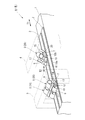
- the prepreg automatic laminating apparatus B is provided on the gantry 1 and is placed so as to be movable back and forth in one direction T1. 2 and a pair of gate-type support columns 3 and 4 disposed at an interval in one direction T1, and supported by one of the gate-type support columns 3 and provided above the laminated table 2.
- a 0 ° layer stacking head 25 and an angle layer stacking head disposed above the stacking table 2 and supported by the other portal-type support column 4 so as to be rotatable about an axis extending in the vertical direction (the prepreg according to the present invention).
- a laminated head) 26 is provided on the gantry 1 and is placed so as to be movable back and forth in one direction T1. 2 and a pair of gate-type support columns 3 and 4 disposed at an interval in one direction T1, and supported by one of the gate-type support columns 3 and provided above the laminated table 2.
- a 0 ° layer stacking head 25 and an angle layer stacking head disposed above the stacking table 2 and
- the 0-degree layer stacking head 25 includes a supply roller 9, a support roller 10, a rotary die cutter 11, a front pressing roller 12, a rear pressing roller 13, and a prepreg.
- a release paper collecting roller 14 for collecting the release paper 7 peeled from the sheet 8 is provided.
- the 0-degree layer laminating head 25 of the present embodiment is different from the conventional 0-degree layer laminating head 5 shown in FIG. 1A in that the prepreg sheet 8 is interposed between the front pressing roller 12 and the rear pressing roller 13.
- the release paper 7 is peeled off from one surface, and the peeled release paper 7 is pressed against the prepreg sheet 8 by the post-pressing roller 13 and attached to the one surface of the prepreg sheet 8 so as to be guided back. It is prepared for.
- the release paper preceding release means 27 includes a release paper guide roller 28 and a scraper roller 29.
- the release paper guide roller 28 is disposed above the front press roller 12 and the rear press roller 13, and is provided by winding the release paper 7 between the front press roller 12 and the rear press roller 13.
- the scraper roller 29 is disposed between the front pressing roller 12 and the release paper guide roller 28 in the one direction T1 and below the release paper guide roller 28, and is one surface of the prepreg sheet 8 that has passed through the front press roller 12.
- the release paper 7 is peeled off from the paper and guided to the release paper guide roller 28.
- the release sheet preceding peeling means 27 is provided between the front pressing roller 12 and the rear pressing roller 13, so that the rear pressing roller 13 Before the release paper 7 is peeled off, the release paper 7 can be peeled off between the front pressing roller 12 and the rear pressing roller 13. Further, the release paper 7 once peeled off by the release paper preceding release means 27 is guided so as to be returned to the rear pressing roller 13, and the prepreg sheet 8 is pressed by the rear pressing roller 13 and attached to one surface of the prepreg sheet 8. Therefore, the prepreg sheet 8 can be pressed by the rear pressing roller 13 through the release paper 7 as in the conventional case, and can be laminated on the workpiece W integrally.
- the release paper 7 When the release paper 7 is peeled off from one surface of the prepreg sheet 8 guided by the rear pressing roller 13, the release paper 7 is once peeled off from the prepreg sheet 8 by the release paper preceding release means 27.
- the adhesive force between the prepreg sheet 8 and the release paper 7 is weakened, and the release paper 7 can be easily peeled from one surface of the prepreg sheet 8. Therefore, like the conventional 0-degree layer stacking head 5 shown in FIG. 1A, the release paper 7 passes through the rear pressing roller 13 and the cutting terminal portion P of the prepreg sheet 8 becomes the workpiece W. It can be prevented from being bounced off by being peeled off.
- the surface of the prepreg sheet 8 is formed in a concavo-convex shape due to the jumping of the cutting terminal portion P, and the cutting terminal portion P is not bent, and a high-quality product is manufactured (a prepreg laminate is formed). ).
- the release paper preceding peeling means 27 is disposed above the front pressing roller 12 and the rear pressing roller 13, and the peeling paper 7 is provided by winding the release paper 7 between the front pressing roller 12 and the rear pressing roller 13. Since the paper guide roller 28 is provided, the release paper 7 can be reliably peeled from one surface of the prepreg sheet 8 while passing through the front pressing roller 12. Further, the release paper 7 can be guided by the release paper guide roller 28 and can be reliably and easily returned to the rear press roller 13.
- the scraper roller 29 is provided between the front pressing roller 12 and the release paper guide roller 28 and below the release paper guide roller 28, the prepreg sheet 8 that has passed through the front press roller 12 more reliably. It becomes possible to peel off the release paper 7 from one side.
- the release paper 7 can be peeled from the prepreg sheet 8 that has passed through the front press roller 12.
- a scraper other than the scraper roller 29 may be used.
- the release paper pre-peeling means 27 may be configured by only the release paper guide roller 28.
- the front pressing roller 12 is only required to be able to guide the prepreg sheet 8 in one direction T1 so as to be laminated on the workpiece W, and necessarily has a function of pressing the prepreg sheet 8 and sticking it to the workpiece W. It does not have to be.
- the angle layer laminating head 26 is disposed on the supply roller 15, the support roller 16, the rotary die cutter 17, and the outer side in the width direction of the work W, respectively.
- the prepreg sheet 8 fed from the roller 16 is provided between a pair of guide rollers 18a and 18b for guiding the prepreg sheet 8 so as to overlap the workpiece W, and the pair of guide rollers 18a and 18b.
- a pair of guides are disposed between the scraper roller 30 for separating the sheet, the one guide roller 18a on the support roller 16 side, and the scraper roller 30 and capable of moving forward and backward in the fiber direction T2 of the prepreg sheet 8.
- the layer shoe 31 is configured to include a release paper collecting roller 20 for collecting the release paper 7.
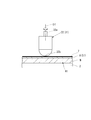
- the laminated shoe 31 is formed by being divided in the width direction of the prepreg sheet 8. That is, the laminated shoe 31 of the present embodiment is configured by arranging a plurality of block-shaped divided shoes 32 side by side. Further, as shown in FIG. 4, each of the divided shoes 32 is formed in a circular arc shape having a tip (lower end) projecting downward in a side view facing the juxtaposed direction. Further, as shown in FIGS. 2 to 4, each of the divided shoes is formed on a central axis O ⁇ b> 1 in the vertical direction and is provided with a rotating shaft 32 a that protrudes upward from the rear end (upper end).
- each of the plurality of divided shoes 32 is provided so as to be rotatable around the central axis O1 with the rotation shaft 32a supported. Further, as shown in FIG. 3, the plurality of divided shoes 32 are provided so as to rotate around the central axis O ⁇ b> 1 in synchronization with the divided shoe rotating mechanism 33.
- the divided shoe rotating mechanism 33 includes a rod-like interlocking member 33a that is rotatably connected to each of the divided shoes 32, and by moving the interlocking member 33a forward and backward in the extending direction, the plurality of divided shoes 32 are moved. It is configured to rotate in synchronization.
- the angle layer laminating head 26 (the supply roller 15, the support roller 16, the pair of guide rollers 18a and 18b, the rotary die cutter 17, the scraper roller 30, and the release paper collecting roller 20) rotates around a rotation axis extending in the vertical direction. Then, the interlocking member 33a is advanced and retracted in synchronism with this, and the plurality of divided shoes 32 are configured to rotate in synchronization with the rotation of the angle layer laminated head 26.
- the split shoe rotation mechanism 33 has a pair of guides in which the extending direction of the pressing portion 32b of each split shoe 32 that presses the prepreg sheet 8 (the front end portion (lower end portion) abutting on one surface side of the prepreg sheet 8).
- the interlocking member 33a is advanced and retracted in synchronism with the rotation of the angle layer laminating head 26 so as to be orthogonal to the fiber direction T2 of the prepreg sheet 8 guided and fed by the rollers 18a and 18b. Move.
- the angle layer stack head 26 of the present embodiment configured as described above, the angle layer stack head 26 is rotated around the rotation axis extending in the vertical direction.
- the fiber direction T2 of the prepreg sheet 8 guided by the pair of guide rollers 18a and 18b is arranged so as to intersect the length direction of the workpiece W at a predetermined intersection angle.
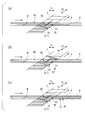
- the divided shoes 32 are rotated by the divided shoe rotating mechanism 33 so that the extending direction of the pressing portion 32b is orthogonal to the fiber direction T2 of the prepreg sheet 8. Further, at this time, as shown in FIG. 3, the plurality of divided shoes 32 are arranged on the scraper roller 30 side, and one end portion of the pressing portion 32 b of each divided shoe 32 is positioned on one side end portion of the workpiece W. And the other end part of the press part 32b is arrange
- the laminated shoe 31 of this embodiment is not formed as a single bar like the conventional laminated shoe 19 but is divided into a plurality of block-shaped divided shoes 32, and therefore the position of each divided shoe 32.
- the stacking shoes 31 are lowered and the pressing portions 32b of the divided shoes 32 are pressed.
- the laminated shoe 31 (the plurality of divided shoes 32) is advanced forward from the initial position while pressing the prepreg sheet 8 from one side. Thereby, the cut piece S1 of the prepreg sheet 8 is affixed to the lamination target piece R1 of the workpiece W.
- the angle layer laminating head 26 includes the scraper roller 30 between the pair of guide rollers 18a and 18b, so that the release paper is reliably released from one surface of the prepreg sheet 8 attached to the workpiece W. 7 is peeled off and wound around the release paper collecting roller 20.
- the next cutting piece S2 of the prepreg sheet 8 is stacked. No pressing is performed at 31, and the next cutting piece S2 is pressed and the release paper 7 is not peeled off as in the case of using the conventional laminated head 6 for the angle layer. Thereby, the cutting piece S2 of the prepreg sheet 8 is accurately positioned and arranged at a predetermined position, and a high-quality product is manufactured (a prepreg laminate is formed).
- the laminating shoe 31 is formed by being divided in the width direction of the prepreg sheet 8, For example, when the prepreg sheet 8 of the angle layer is laminated on the work W at a small crossing angle of 45 degrees with respect to the length direction of the work W, the position of each divided shoe 32 formed by dividing the laminated shoe 31 is set as the prepreg sheet. It is possible to dispose and arrange in the fiber direction T2 of 8.
- each of the plurality of divided shoes 32 is rotatably supported around a central axis O1 extending in the vertical direction, and each divided shoe 32 can be rotated about the central axis O1, so that the crossing angle can be reduced. Regardless of the size, the direction of each divided shoe 32 can be easily adjusted to the fiber direction T2 of the prepreg sheet 8. Thereby, each divided shoe 32 (laminated shoe 31) can be advanced and retracted to suitably stack the prepreg sheet 8 of the angle layer on the workpiece W.
- the plurality of divided shoes 32 can be rotated synchronously by the divided shoe rotating mechanism 33, the direction of each divided shoe 32 can be more easily adjusted to the fiber direction T2 of the prepreg sheet 8.
- the cutting piece S1 of the prepreg sheet 8 can be accurately positioned and arranged at a predetermined position, and a high-quality product is manufactured ( It is possible to form a prepreg laminate.
- a scraper roller 30 for separating the release paper 7 from one surface of the prepreg sheet 8 is provided between the pair of guide rollers 18a and 18b, one surface of the prepreg sheet 8 laminated on the workpiece W by the laminated shoe 31.
- the release paper 7 can be reliably peeled off (removed) and collected.
- the laminated table 2 is configured to advance and retreat on the gantry 1 in one direction T1, but the gate-type support columns 3 and 4 advance and retract in one direction T1 with respect to the laminated table 2. It may be configured. That is, the workpiece W only needs to be placed on the lamination table 2 so as to be able to advance and retreat relative to the prepreg lamination heads 25 and 26 in one direction T1.
- ADVANTAGE OF THE INVENTION it becomes possible to press only the cutting piece of the prepreg sheet laminated
Landscapes
- Engineering & Computer Science (AREA)
- Robotics (AREA)
- Chemical & Material Sciences (AREA)
- Composite Materials (AREA)
- Mechanical Engineering (AREA)
- Moulding By Coating Moulds (AREA)
- Reinforced Plastic Materials (AREA)
- Casting Or Compression Moulding Of Plastics Or The Like (AREA)
- Processing And Handling Of Plastics And Other Materials For Molding In General (AREA)
- Laminated Bodies (AREA)
Priority Applications (2)
| Application Number | Priority Date | Filing Date | Title |
|---|---|---|---|
| EP11747516.0A EP2540478A4 (de) | 2010-02-26 | 2011-02-25 | Prepreg-beschichtungskopf und damit ausgestattete automatische prepreg-beschichtungsvorrichtung |
| US13/576,059 US20120298309A1 (en) | 2010-02-26 | 2011-02-25 | Prepreg lamination head and prepreg automatic lamination device including the same |
Applications Claiming Priority (2)
| Application Number | Priority Date | Filing Date | Title |
|---|---|---|---|
| JP2010-041916 | 2010-02-26 | ||
| JP2010041916A JP5422439B2 (ja) | 2010-02-26 | 2010-02-26 | プリプレグ積層ヘッド及びこれを備えたプリプレグ自動積層装置 |
Publications (1)
| Publication Number | Publication Date |
|---|---|
| WO2011105560A1 true WO2011105560A1 (ja) | 2011-09-01 |
Family
ID=44506957
Family Applications (1)
| Application Number | Title | Priority Date | Filing Date |
|---|---|---|---|
| PCT/JP2011/054329 Ceased WO2011105560A1 (ja) | 2010-02-26 | 2011-02-25 | プリプレグ積層ヘッド及びこれを備えたプリプレグ自動積層装置 |
Country Status (4)
| Country | Link |
|---|---|
| US (1) | US20120298309A1 (de) |
| EP (1) | EP2540478A4 (de) |
| JP (1) | JP5422439B2 (de) |
| WO (1) | WO2011105560A1 (de) |
Cited By (4)
| Publication number | Priority date | Publication date | Assignee | Title |
|---|---|---|---|---|
| JP2014133340A (ja) * | 2013-01-09 | 2014-07-24 | Mitsubishi Rayon Co Ltd | 複合材料の製造装置および製造方法 |
| JP2015063049A (ja) * | 2013-09-24 | 2015-04-09 | 東邦テナックス株式会社 | プリプレグ自動積層装置、プリプレグ積層体の製造方法及び繊維強化複合材料製造装置 |
| JP2015535761A (ja) * | 2012-10-05 | 2015-12-17 | ザ・ボーイング・カンパニーTheBoeing Company | 凸型の曲率半径を有する表面上での複合テープラミネーション加工の方法 |
| US20240416433A1 (en) * | 2021-10-11 | 2024-12-19 | Hilti Aktiengesellschaft | Drill bit with improved removal of the drill core |
Families Citing this family (13)
| Publication number | Priority date | Publication date | Assignee | Title |
|---|---|---|---|---|
| US8808490B2 (en) | 2011-08-04 | 2014-08-19 | The Boeing Company | Methods for laminating composites |
| US8826957B2 (en) * | 2012-08-31 | 2014-09-09 | General Electric Company | Methods and systems for automated ply layup for composites |
| JP6288495B2 (ja) * | 2013-11-06 | 2018-03-07 | 三菱重工業株式会社 | プリプレグシート自動積層装置、及びプリプレグシート積層方法 |
| JP6287296B2 (ja) | 2014-02-10 | 2018-03-07 | 三菱重工業株式会社 | プリプレグシート自動積層装置 |
| US10011080B2 (en) * | 2014-09-29 | 2018-07-03 | The Boeing Company | Composite part forming system |
| ITUB20150273A1 (it) * | 2015-05-06 | 2016-11-06 | Avio Spa | Macchina di formatura di un corpo cavo, in particolare un involucro di un motore a propellente solido, e testa di deposito per tale macchina di formatura |
| ES2846002T3 (es) | 2015-06-16 | 2021-07-28 | Gh Craft Ltd | Dispositivo de moldeo y método de producción |
| KR102492997B1 (ko) | 2015-11-25 | 2023-01-31 | 가부시키가이샤 아데카 | 성형장치, 제조방법 및 섬유강화수지 재료 |
| DE102016116799A1 (de) | 2016-09-08 | 2018-03-22 | Dieffenbacher GmbH Maschinen- und Anlagenbau | Tapelegevorrichtung und Tapelegeverfahren zum simultanen Legen von Tapes mit variablem Abstand |
| JP2020066168A (ja) * | 2018-10-24 | 2020-04-30 | 三菱重工業株式会社 | プリプレグ自動積層装置 |
| IT201900009990A1 (it) * | 2019-06-25 | 2020-12-25 | Bridgestone Europe Nv Sa | Metodo ed unita' di lavorazione per inserire dei dispositivi elettronici atti a comunicare in radiofrequenza in rispettive custodie di gomma |
| CN112388949A (zh) * | 2020-10-28 | 2021-02-23 | 廖木全 | 碳纤维叶片加工方法、叶片及风扇 |
| CN114074437B (zh) * | 2021-08-10 | 2023-12-05 | 中山大学 | 一种纤维复合材料交叉肋条薄铺层及其制备方法 |
Citations (9)
| Publication number | Priority date | Publication date | Assignee | Title |
|---|---|---|---|---|
| JPS5839845U (ja) * | 1981-09-11 | 1983-03-16 | 東芝機械株式会社 | テ−プ自動貼付装置 |
| JPH01294165A (ja) * | 1988-05-18 | 1989-11-28 | Shin Nippon Koki Kk | テープの自動貼付装置 |
| JPH02153938A (ja) * | 1988-12-06 | 1990-06-13 | Toshiba Mach Co Ltd | 繊維角度の異なるプリプレグシートの製造または積層装置 |
| JPH1076622A (ja) * | 1996-08-05 | 1998-03-24 | Boeing North American Inc | 第1のキャリヤテープの上に第2の交差プライテープのセグメントを重ねるための方法および装置 |
| JP2004017625A (ja) | 2002-06-20 | 2004-01-22 | Kawasaki Heavy Ind Ltd | プリプレグ高速積層方法及びその装置 |
| JP2004017633A (ja) | 2002-06-20 | 2004-01-22 | Kawasaki Heavy Ind Ltd | プリプレグ自動積層方法及びその装置 |
| JP2004181683A (ja) | 2002-11-29 | 2004-07-02 | Kawasaki Heavy Ind Ltd | プリプレグ幅変更自動積層方法及びその装置 |
| JP2006289619A (ja) * | 2005-04-05 | 2006-10-26 | Fukui Prefecture | 多軸多層補強シートの製造方法及び製造装置 |
| JP2010041916A (ja) | 2008-07-31 | 2010-02-18 | Asml Holding Nv | アクチュエータコイルの冷却 |
Family Cites Families (8)
| Publication number | Priority date | Publication date | Assignee | Title |
|---|---|---|---|---|
| EP0113717B1 (de) * | 1982-07-19 | 1987-12-23 | The Boeing Company | Verfahren und vorrichtung zum zusammendrucken von filamenten |
| US4915771A (en) * | 1987-10-08 | 1990-04-10 | The Boeing Company | Segmented tape shoe |
| JPH0725143B2 (ja) * | 1988-03-28 | 1995-03-22 | 新日本工機株式会社 | テープの自動貼付装置 |
| DE4130269C2 (de) * | 1990-09-13 | 1996-05-23 | Toshiba Machine Co Ltd | Verfahren und Vorrichtung zum Herstellen laminierter Prepreg-Teile |
| US20060118244A1 (en) * | 2004-12-02 | 2006-06-08 | The Boeing Company | Device for laying tape materials for aerospace applications |
| US7867352B2 (en) * | 2006-02-13 | 2011-01-11 | The Boeing Company | Composite material placement method and system |
| US7591294B2 (en) * | 2007-11-29 | 2009-09-22 | Spirit Aerosystems, Inc. | Material placement method and apparatus |
| JP5439225B2 (ja) * | 2010-02-26 | 2014-03-12 | 三菱重工業株式会社 | プリプレグ積層ヘッド及びこれを備えたプリプレグ自動積層装置 |
-
2010
- 2010-02-26 JP JP2010041916A patent/JP5422439B2/ja active Active
-
2011
- 2011-02-25 EP EP11747516.0A patent/EP2540478A4/de not_active Withdrawn
- 2011-02-25 US US13/576,059 patent/US20120298309A1/en not_active Abandoned
- 2011-02-25 WO PCT/JP2011/054329 patent/WO2011105560A1/ja not_active Ceased
Patent Citations (9)
| Publication number | Priority date | Publication date | Assignee | Title |
|---|---|---|---|---|
| JPS5839845U (ja) * | 1981-09-11 | 1983-03-16 | 東芝機械株式会社 | テ−プ自動貼付装置 |
| JPH01294165A (ja) * | 1988-05-18 | 1989-11-28 | Shin Nippon Koki Kk | テープの自動貼付装置 |
| JPH02153938A (ja) * | 1988-12-06 | 1990-06-13 | Toshiba Mach Co Ltd | 繊維角度の異なるプリプレグシートの製造または積層装置 |
| JPH1076622A (ja) * | 1996-08-05 | 1998-03-24 | Boeing North American Inc | 第1のキャリヤテープの上に第2の交差プライテープのセグメントを重ねるための方法および装置 |
| JP2004017625A (ja) | 2002-06-20 | 2004-01-22 | Kawasaki Heavy Ind Ltd | プリプレグ高速積層方法及びその装置 |
| JP2004017633A (ja) | 2002-06-20 | 2004-01-22 | Kawasaki Heavy Ind Ltd | プリプレグ自動積層方法及びその装置 |
| JP2004181683A (ja) | 2002-11-29 | 2004-07-02 | Kawasaki Heavy Ind Ltd | プリプレグ幅変更自動積層方法及びその装置 |
| JP2006289619A (ja) * | 2005-04-05 | 2006-10-26 | Fukui Prefecture | 多軸多層補強シートの製造方法及び製造装置 |
| JP2010041916A (ja) | 2008-07-31 | 2010-02-18 | Asml Holding Nv | アクチュエータコイルの冷却 |
Non-Patent Citations (1)
| Title |
|---|
| See also references of EP2540478A4 |
Cited By (4)
| Publication number | Priority date | Publication date | Assignee | Title |
|---|---|---|---|---|
| JP2015535761A (ja) * | 2012-10-05 | 2015-12-17 | ザ・ボーイング・カンパニーTheBoeing Company | 凸型の曲率半径を有する表面上での複合テープラミネーション加工の方法 |
| JP2014133340A (ja) * | 2013-01-09 | 2014-07-24 | Mitsubishi Rayon Co Ltd | 複合材料の製造装置および製造方法 |
| JP2015063049A (ja) * | 2013-09-24 | 2015-04-09 | 東邦テナックス株式会社 | プリプレグ自動積層装置、プリプレグ積層体の製造方法及び繊維強化複合材料製造装置 |
| US20240416433A1 (en) * | 2021-10-11 | 2024-12-19 | Hilti Aktiengesellschaft | Drill bit with improved removal of the drill core |
Also Published As
| Publication number | Publication date |
|---|---|
| JP5422439B2 (ja) | 2014-02-19 |
| EP2540478A4 (de) | 2017-11-15 |
| JP2011177927A (ja) | 2011-09-15 |
| US20120298309A1 (en) | 2012-11-29 |
| EP2540478A1 (de) | 2013-01-02 |
Similar Documents
| Publication | Publication Date | Title |
|---|---|---|
| JP5422439B2 (ja) | プリプレグ積層ヘッド及びこれを備えたプリプレグ自動積層装置 | |
| JP5439225B2 (ja) | プリプレグ積層ヘッド及びこれを備えたプリプレグ自動積層装置 | |
| KR101494467B1 (ko) | 흑연 테이프 공급 및 후면지 권취 장치 | |
| JP4940301B2 (ja) | レイアップ配列及び構造配列並びに航空宇宙産業用構成部品の製造方法 | |
| KR101436386B1 (ko) | 첨단 복합 맞춤 블랭크의 신속한 자동화 제작을 위한 시스템 및 방법 | |
| KR20120132484A (ko) | 라벨 제조 장치 및 라벨 인쇄기 | |
| JP7726638B2 (ja) | フィルム製品の製造方法及びその製造装置 | |
| CN105612045A (zh) | 预浸片材自动叠层装置以及预浸片材叠层方法 | |
| US7621479B2 (en) | Supply-roll switching apparatus | |
| JP5215382B2 (ja) | 支持テープからプリプレグを分離する退避可能な分離装置を備えた複合材料レイアップヘッド | |
| CN103358654A (zh) | 滚筒式贴合机 | |
| JP7706061B2 (ja) | 複合テープのアプリケーターヘッド | |
| TW201808765A (zh) | 用於轉換兩層式紙巾織物的紙巾轉換機器的饋送單元 | |
| JP2678931B2 (ja) | 繊維角度の異なるプリプレグシートの製造または積層装置 | |
| CN108502617A (zh) | 胶带底板设置系统及采用其的胶带分条机 | |
| JPH04122611A (ja) | プリプレグテープの切断編集方法およびその装置 | |
| JP2008272899A (ja) | 積層成形装置および積層成形方法 | |
| JP6525011B2 (ja) | エアダムを形成する方法 | |
| CN117142209A (zh) | 一种随动式放卷装置 | |
| JP2004262561A (ja) | 巻取り装置 | |
| CN104553286B (zh) | 一种复合印刷装置以及印刷方法 | |
| CN113665880A (zh) | 一种印品多层贴膜装置 | |
| US20260035195A1 (en) | Method and apparatus for preparing transfer tape constructs for paper web turn-up processes | |
| KR20150116984A (ko) | 일방향 프리프레그를 이용한 다축 보강 적층시트 제조방법 | |
| CN117842761A (zh) | 一种贴胶、撕膜、贴膜一体设备 |
Legal Events
| Date | Code | Title | Description |
|---|---|---|---|
| 121 | Ep: the epo has been informed by wipo that ep was designated in this application |
Ref document number: 11747516 Country of ref document: EP Kind code of ref document: A1 |
|
| WWE | Wipo information: entry into national phase |
Ref document number: 13576059 Country of ref document: US |
|
| WWE | Wipo information: entry into national phase |
Ref document number: 2011747516 Country of ref document: EP |
|
| NENP | Non-entry into the national phase |
Ref country code: DE |