WO2011129384A1 - Dispositif de poignée extérieure pour porte de véhicule - Google Patents
Dispositif de poignée extérieure pour porte de véhicule Download PDFInfo
- Publication number
- WO2011129384A1 WO2011129384A1 PCT/JP2011/059237 JP2011059237W WO2011129384A1 WO 2011129384 A1 WO2011129384 A1 WO 2011129384A1 JP 2011059237 W JP2011059237 W JP 2011059237W WO 2011129384 A1 WO2011129384 A1 WO 2011129384A1
- Authority
- WO
- WIPO (PCT)
- Prior art keywords
- bolt
- base plate
- outer panel
- engaged
- locking
- Prior art date
- Legal status (The legal status is an assumption and is not a legal conclusion. Google has not performed a legal analysis and makes no representation as to the accuracy of the status listed.)
- Ceased
Links
Images





Classifications
-
- E—FIXED CONSTRUCTIONS
- E05—LOCKS; KEYS; WINDOW OR DOOR FITTINGS; SAFES
- E05B—LOCKS; ACCESSORIES THEREFOR; HANDCUFFS
- E05B79/00—Mounting or connecting vehicle locks or parts thereof
- E05B79/02—Mounting of vehicle locks or parts thereof
- E05B79/06—Mounting of handles, e.g. to the wing or to the lock
-
- E—FIXED CONSTRUCTIONS
- E05—LOCKS; KEYS; WINDOW OR DOOR FITTINGS; SAFES
- E05B—LOCKS; ACCESSORIES THEREFOR; HANDCUFFS
- E05B17/00—Accessories in connection with locks
- E05B17/0012—Accessories in connection with locks for lock parts held in place before or during mounting on the wing
-
- E—FIXED CONSTRUCTIONS
- E05—LOCKS; KEYS; WINDOW OR DOOR FITTINGS; SAFES
- E05B—LOCKS; ACCESSORIES THEREFOR; HANDCUFFS
- E05B81/00—Power-actuated vehicle locks
- E05B81/54—Electrical circuits
- E05B81/64—Monitoring or sensing, e.g. by using switches or sensors
- E05B81/76—Detection of handle operation; Detection of a user approaching a handle; Electrical switching actions performed by door handles
-
- E—FIXED CONSTRUCTIONS
- E05—LOCKS; KEYS; WINDOW OR DOOR FITTINGS; SAFES
- E05B—LOCKS; ACCESSORIES THEREFOR; HANDCUFFS
- E05B85/00—Details of vehicle locks not provided for in groups E05B77/00 - E05B83/00
- E05B85/10—Handles
-
- E—FIXED CONSTRUCTIONS
- E05—LOCKS; KEYS; WINDOW OR DOOR FITTINGS; SAFES
- E05B—LOCKS; ACCESSORIES THEREFOR; HANDCUFFS
- E05B85/00—Details of vehicle locks not provided for in groups E05B77/00 - E05B83/00
- E05B85/10—Handles
- E05B85/14—Handles pivoted about an axis parallel to the wing
- E05B85/16—Handles pivoted about an axis parallel to the wing a longitudinal grip part being pivoted at one end about an axis perpendicular to the longitudinal axis of the grip part
-
- Y—GENERAL TAGGING OF NEW TECHNOLOGICAL DEVELOPMENTS; GENERAL TAGGING OF CROSS-SECTIONAL TECHNOLOGIES SPANNING OVER SEVERAL SECTIONS OF THE IPC; TECHNICAL SUBJECTS COVERED BY FORMER USPC CROSS-REFERENCE ART COLLECTIONS [XRACs] AND DIGESTS
- Y10—TECHNICAL SUBJECTS COVERED BY FORMER USPC
- Y10S—TECHNICAL SUBJECTS COVERED BY FORMER USPC CROSS-REFERENCE ART COLLECTIONS [XRACs] AND DIGESTS
- Y10S292/00—Closure fasteners
- Y10S292/53—Mounting and attachment
-
- Y—GENERAL TAGGING OF NEW TECHNOLOGICAL DEVELOPMENTS; GENERAL TAGGING OF CROSS-SECTIONAL TECHNOLOGIES SPANNING OVER SEVERAL SECTIONS OF THE IPC; TECHNICAL SUBJECTS COVERED BY FORMER USPC CROSS-REFERENCE ART COLLECTIONS [XRACs] AND DIGESTS
- Y10—TECHNICAL SUBJECTS COVERED BY FORMER USPC
- Y10T—TECHNICAL SUBJECTS COVERED BY FORMER US CLASSIFICATION
- Y10T292/00—Closure fasteners
- Y10T292/57—Operators with knobs or handles
Definitions
- the present invention is for a vehicle including a handle body having a grip portion disposed on the outer side of an outer panel provided in a vehicle door, and a base plate that is engaged with the handle body and fixed to the inner surface of the outer panel.
- the present invention relates to a door out-handle device.
- Patent Document 1 An out-handle apparatus that is assembled to a door by fastening a handle assembly including a handle body having a grip portion to a base member disposed inside an outer panel of the door with a pair of bolts is disclosed in Patent Document 1. Is known.
- the present invention has been made in view of the above circumstances, and provides an out-handle apparatus for a vehicle door that facilitates assembly of a handle body to a door and enables reduction in the number of parts and work man-hours. With the goal.
- the present invention provides a handle main body having a grip portion disposed on the outer side of an outer panel included in a vehicle door, and is fixed to the inner surface of the outer panel by engaging the handle main body.
- a first bolt that has an enlarged head and is screwed into one longitudinal end of the gripping part or one longitudinal end of the gripping part The base end is planted and the second bolt with the nut screwed to the front end side is inserted and engaged, and the other end in the longitudinal direction of the gripping portion is provided.
- An insertion hole that is inserted into the outer panel and is provided with a locking groove provided on the outer periphery thereof, and the insertion portion is configured to engage the first bolt or the second bolt with the locking hole.
- the handle body is provided on the outer panel so that the handle body can be temporarily assembled to the outer panel, and one end of the base plate can be engaged with the enlarged diameter head or the nut.
- a second engaging recess that accommodates the projecting portion so that the other end portion of the base plate can be engaged with the locking groove of the projecting portion by rotating about the axis of the bolt.
- the first feature is that the base plate is provided so as to open to the side edge of the plate.
- the locking hole includes an insertion hole portion through which the enlarged diameter head portion or the nut can be inserted, a shaft portion of the first bolt, or a second bolt. Is formed of a locking slit portion that is continuous with the insertion hole portion, and the first bolt or the second bolt is inserted into the locking hole.
- the opening direction of the first engaging recess is the opening direction of the engaging slit to the insertion hole
- the second feature is that the direction is set in a different direction.
- the penetration portion is provided with a through hole through which a harness connected to an electrical component disposed in the grip portion is led out. It is characterized by.
- the present invention provides that, in addition to any of the configurations of the first to third features, the base plate is formed in a shape that exerts elasticity between the locking groove of the protrusion and the outer panel.
- the fourth feature is formed in a shape that exerts elasticity between the locking groove of the protrusion and the outer panel.
- substrate 22 of embodiment corresponds to the electrical component of this invention.
- the first bolt or the second bolt on one end side of the gripping portion of the handle body is engaged with the locking hole, and the projecting portion is inserted into the insertion hole.
- the handle main body is fixed to the outer panel by tightening the first bolt or nut so that the nut screwed to the head or the second bolt is brought into contact with and engaged with one end of the base plate. Therefore, it is not necessary to support the handle body by hand when the handle body is assembled to the outer panel, the assembly of the handle body to the vehicle door is facilitated, and the number of parts is reduced because there is only one fastening point. In addition, the assembly man-hours can be reduced.
- the base plate is engaged with the handle body by rotating around the axis of the first bolt or the second bolt, and the base plate only moves in parallel with the inner surface of the outer panel. Therefore, the rotating operation of the base plate on the inner surface side of the outer panel having only a small space is easy.
- the locking hole allows insertion of the enlarged diameter head portion or the insertion hole portion through which the nut can be inserted, and the shaft portion of the first bolt or the second bolt. It is made up of a locking slit portion that is continuous with the insertion hole so that the enlarged diameter head or the nut cannot be inserted, and the opening direction of the first engaging recess provided on the base plate so as to open to the outer edge is related. Since it is different from the opening direction of the stop slit portion to the insertion hole portion, the shaft portion of the first bolt or the second bolt is inserted into the lock slit portion of the lock hole, and the first bolt or the second bolt is inserted.
- the shaft portion of the first bolt or the second bolt is the locking slit portion.
- the first bolt or the second bolt This makes it impossible to move the bolts, making it easier to assemble the handle body to the vehicle door.
- the harness connected to the electrical component disposed in the gripping portion is led out from the through hole provided with the entry portion, the harness between the handle body and the outer panel is provided. Can be prevented from being caught.
- the handle body since the base plate exerts elasticity between the locking groove and the outer panel in a state where the base plate is engaged with the locking groove of the entry portion, the handle body is fastened. It is possible to prevent the base plate from rattling.
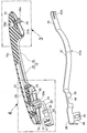
- FIG. 1 is a side view of a vehicle door.
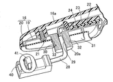
- FIG. 2 is a perspective view showing the handle main body in a state broken at the center in the width direction and the base plate with which the handle main body is engaged with each other.
- First embodiment 3 is an enlarged view of a portion indicated by an arrow 3 in FIG.
- First embodiment 4 is an enlarged view of a portion indicated by an arrow 4 in FIG.
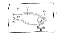
- FIG. 5 is a perspective view showing the inner surface side of the outer panel in a state where the handle body is not assembled.
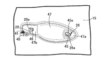
- FIG. 6 is a perspective view corresponding to FIG. 6 in a state where the handle body is temporarily assembled.
- FIG. 7 is a perspective view corresponding to FIG.
- FIG. 6 in a state where the base plate is engaged with the handle body side.
- FIG. 8 is a perspective view corresponding to FIG. 6 with the handle body fixed to the outer panel.
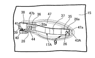
- FIG. 9 is a view taken in the direction of arrow 9 in FIG.
- FIG. 10 is a perspective view corresponding to FIG. 3 of the second embodiment.
- FIG. 11 is a perspective view showing a first modification of the base plate.
- FIG. 12 is a perspective view showing a second modification of the base plate. (Second modification)
- the first embodiment of the present invention will be described with reference to FIGS. 1 to 9.
- the outer panel 15 is provided with a handle body 16 having a grip portion 16a that extends long in the front-rear direction of the vehicle and is disposed on the outer side of the outer panel 15.
- the handle body 16 is connected to the outer panel 15. It is fixed to the outer panel 15 by engaging with a base plate 17A (see FIG. 2) fixed to the inner surface.
- the outer panel 15 is provided with an insertion recess 18 that allows a part of a hand holding the holding portion 16a to be inserted.
- the handle main body 16 is made of a synthetic resin handle base 19 that extends over the entire length of the gripping portion 16a, and a synthetic resin that is joined to the back of the rear half of the handle base 19 by a plurality of screw members 21.
- a cover member 20 is provided, and the handle base 19 and a part of the cover member 20 constitute the grip portion 16a.
- a substrate 22 fixed to the inner surface of the cover member 20 and the gripping portion 16a are disposed on the substrate 22 in order to detect a state in which the vehicle user holds the substrate.
- the antenna 24 disposed on the substrate 22 so as to be sandwiched between the sensor 23 and the substrate 22 are accommodated.
- a flange portion 25a projecting outward in the radial direction is formed at one end of the one end portion (front end portion in this embodiment) of the grip portion 16a on the outer panel 15 side.
- a cylindrical nut 25 is press-fitted, and a shaft portion 26b of a first bolt 26 having an enlarged head portion 26a is screwed into the nut 25.
- a first seal formed in a flat plate shape is integrally formed with a cover portion 27a that covers the flange portion 25a of the nut 25 from both sides on the surface of the one end portion of the grip portion 16a facing the outer panel 15 side.
- a member 27A is mounted, one end of the gripping portion 16a is brought into contact with the outer surface of the outer panel 15 via the first seal member 27A, and the first bolt 26 is a central portion of the first seal member 27A. And is screwed to one end of the gripping portion 16a so as to protrude outward.
- the other end portion in the longitudinal direction of the gripping portion 16a (the rear end portion in this embodiment) is provided with a protrusion 20a that protrudes into the outer panel 15.
- the rush portion 20a is provided integrally with the cover member 20 that constitutes a part of the grip portion 16a.
- the intrusion portion 20a is formed in a square tube shape having a square cross-sectional shape, and the harness 28 connected to the substrate 22 which is an electric component disposed in the grip portion 16a is externally provided.
- a through hole 29 to be led out is provided in the entry portion 20a.
- a flat plate-like second seal member 31 having an opening 30 through which the projecting portion 20a is inserted is attached to a surface of the other end portion of the grip portion 16a facing the outer panel 15 side.
- the other end of the gripping portion 16 a is in contact with the outer surface of the outer panel 15 via the second seal member 31.
- the protruding portion 20a protrudes from the second seal member 31, and a pair of locking grooves 32 extending in the vertical direction are formed on the outer periphery of the protruding portion 20a at the portion protruding from the second seal member 31. , 32 are provided.
- the base plate 17A is in contact with the inner surface of the outer panel 15 on one end (front end in this embodiment) side of the handle main body 16 and the enlarged head portion 26a of the first bolt 26.
- a first engagement portion 35 that can be engaged with the inner surface of the outer panel 15 on the other end (rear end in this embodiment) side of the handle main body 16 and the protrusion 20a.
- a second engaging portion 36 that can be engaged with the outer periphery, a bending portion 37 that connects the first and second engaging portions 35, 36 and swells on the opposite side of the outer panel 15;
- An abutment plate portion 38 that is continuous with the second engagement portion 36 on the opposite side of the portion 37 and abuts against the inner surface of the outer panel 15 is integrated with the passenger vehicle corresponding to the grip portion 16 a of the handle body 16. It will extend long in the front-rear direction It is formed on.
- the first engaging portion 35 at one end of the base plate 17A is formed in a flat plate shape and accommodates the first bolt 26 so that the enlarged diameter head portion 26a can be engaged with the first engaging portion 35.
- a first engagement recess 43 ⁇ / b> A is provided in the first engagement portion 35.
- the second engagement portion 36 at the other end of the base plate 17A is formed in a trapezoidal shape so as to protrude away from the outer panel 15, and the first bolt 26 is accommodated in the first engagement recess 43A.
- the abutting plate portion 38 is formed in a flat plate shape, and a connector holding portion 39 is connected to the lower side edge of the abutting plate portion 38 at a right angle.
- the connector holding portion 39 has a holding hole for elastically engaging and holding the clip 41 attached to the connector 40 to which the harness 28 led out from the through hole 29 of the entry portion 20a is connected. 42 is formed.
- the first and second engaging recesses 43A, 44 are provided in the base plate 17A so as to open to the side edge of the base plate 17A.
- the first engaging recess 43A is a passenger vehicle. Are provided at the front edge of the front end portion of the first engagement portion 35 so as to be opened forward in the front-rear direction, and provided at the lower edge of the second engagement portion 36 so as to open downward. It is done.
- the second engagement portion 36 has a trapezoidal shape, in the state where the second engagement portion 36 is engaged with the engagement groove 32 of the entry portion 20a, the engagement groove 32.
- the second engaging portion 36 exhibits elasticity between 15.
- the outer panel 15 has an enlarged diameter head portion 26 a and a locking hole 45 through which the first bolt 26 that is screwed to one end in the longitudinal direction of the gripping portion 16 a is inserted and engaged, An insertion hole 46 through which the protrusion 20a provided at the other end in the longitudinal direction of the grip 16a is inserted is provided.
- the outer panel 15 is provided with a bulging portion 47 that swells inwardly so as to form an insertion recess 18 provided on the outer surface side of the outer panel 15.
- the locking hole 45 is provided in the first flat part 47a formed at the front part of the protruding part 47, and the second flat part 47b formed at the rear part of the bulging part 47 along the front-rear direction is An insertion hole 46 is provided.
- the locking hole 45 allows insertion of the insertion hole portion 45a through which the enlarged diameter head portion 26a can be inserted and the shaft portion 26b of the first bolt 26, the insertion of the enlarged diameter head portion 26a becomes impossible.
- the handle main body 16 in a state in which the protrusion 20a is inserted into the insertion hole 46 is configured to be engaged with the engagement hole 45 of the first bolt 26.
- the outer panel 15 can be temporarily assembled to the outer panel 15 as a result.
- the shaft portion 26b is moved toward the locking slit portion 45b, whereby the first bolt 26 is inserted into the locking hole 45.
- the handle body 16 can be temporarily assembled to the outer panel 15 by inserting the protrusion 20a into the insertion hole 46 while engaging the.
- the base plate 17A in a state where the first bolt 26 is accommodated in the first engagement recess 43A is attached to the first base plate 17A.
- the second engaging portion 36 can be engaged with the locking grooves 32 of the rush portion 20a by rotating around the axis of the bolt 26, and as shown in FIG.
- the second engaging portion 36 is completely engaged with the engaging grooves 32 on the outer periphery of the projecting portion 20a while the projecting portion 20a is accommodated in the second engaging recess 44, and the second engaging portion 36 is flattened portion 47b.
- FIG. 9 shows a state in which the first bolt 26 is inserted into and engaged with the locking hole 45 and the other end of the base plate 17A is engaged with the locking groove 32 of the protrusion 20a.
- the opening direction of the first engaging recess 43A is set in a direction different from the opening direction of the locking slit 45b to the insertion hole 45a.
- the first engagement The opening direction of the recess 43A is forward along the front-rear direction of the passenger vehicle, whereas the opening direction of the locking slit portion 45b to the insertion hole 45a is rearward along the front-rear direction of the passenger vehicle.
- Locking for inserting and engaging the first bolt 26 having the enlarged diameter head portion 26a and screwed into one end portion in the longitudinal direction of the gripping portion 16a A hole 45 and an insertion hole 46 that is provided at the other end in the longitudinal direction of the gripping part 16a and that is inserted into the outer panel 15 and through which the insertion part 20a is inserted, allow the first bolt 26 to be inserted into the locking hole 45.
- the handle body 16 can be temporarily assembled to the outer panel 15 so as to be inserted into the insertion hole 46 while being engaged with the insertion hole 46, and is provided on the outer panel 15.
- the second engaging recess 44 to be accommodated is provided in the base plate 17A so as to open to the side edge of the base plate 17A.
- the base plate 17A in a state in which the first bolt 26 is received in the first engagement recess 43A is rotated around the axis of the first bolt 26.
- the other end portion of the base plate 17A can be engaged with the locking grooves 32 on the outer periphery of the protrusion 20a, and the enlarged head portion 26a of the first bolt 26 is further brought into contact with one end portion of the base plate 17A.
- the handle body 16 can be fixed to the outer panel 15 by tightening the first bolts 26 so as to contact and engage.
- the assembly of the handle body 16 to the vehicle door D is facilitated, and the fastening point is one place.
- the number of parts can be reduced and the number of assembly work steps can be reduced.
- the engagement of the base plate 17A with the handle body 16 is performed by rotating around the axis of the first bolt 26, and the base plate 17A only moves in parallel with the inner surface of the outer panel 15. Therefore, the rotating operation of the base plate 17A on the inner surface side of the outer panel 15 having only a narrow space is easy.
- the locking hole 45 provided in the outer panel 15 allows the insertion hole portion 45a through which the enlarged diameter head portion 26a can be inserted and the shaft portion 26b of the first bolt 26 to be inserted through the enlarged diameter head portion. 26a, and a locking slit portion 45b connected to the insertion hole 45a.
- the first bolt 26 is inserted into and engaged with the locking hole 45, and the locking groove 32 of the protrusion 20a. With the other end of the base plate 17A engaged, the opening direction of the first engaging recess 43A is set to a direction different from the opening direction of the locking slit 45b to the insertion hole 45a.
- one end of the base plate 17A is inserted in a state in which the shaft portion 26b of the first bolt 26 is inserted into the locking slit portion 45b of the locking hole 45 and the first bolt 26 is inserted into and engaged with the locking hole 45.
- the shaft portion 26b of the first bolt 26 does not move from the locking slit portion 45b to the insertion hole portion 45a when engaging, and one end portion of the base plate 17A is engaged with the first bolt 26.
- the first bolt 26 cannot be moved, and the handle body 16 is assembled to the vehicle door D. Becomes even easier.
- the penetration portion 20a provided at the other end portion of the handle body 16 is provided with a through hole 29 through which the harness 28 connected to the substrate 22 provided in the grip portion 16a is led out, It is possible to prevent the harness 28 from being caught between the panels 15.
- the second engaging portion 36 at the other end of the base plate 17A is formed in a shape that exerts elasticity between the locking groove 32 of the protruding portion 20a and the outer panel 15, the handle body 16 is fastened. It is possible to prevent rattling of the base plate 17A in the finished state.
- a proximal end portion of a second bolt 49 is implanted at one end portion of the grip portion 16a in the handle body 16, and the second bolt 49 is projected from the center portion at one end portion of the grip portion 16a.
- a flat plate-like first seal member 27B is attached.
- a nut 50 is screwed to the distal end side of the second bolt 49, and the nut 50 is screwed to the distal end side in a locking hole 45 (see the first embodiment) provided in the outer panel 15. It is possible to insert and engage the second bolt 49 in the combined state, and the first engagement recess 43A (first embodiment) provided in the first engagement portion 35 of the base plate 17A. Reference) can accommodate the second bolt 49 by engaging the nut 50 with the first engaging portion 35.
- the same effect as that of the first embodiment can be obtained also by the second embodiment.
- the front end part front of the 1st engaging part 35 which made it possible to engage the nut 50 screwed by the diameter expansion head 26a of the 1st volt
- the first engagement recess 43A is provided at the edge so as to open forward in the front-rear direction of the passenger vehicle.
- the first engagement recess is provided in the first engagement recess with the first bolt 26 or the second bolt 49.
- the base plate in a state of accommodating the first bolt 26 or the second bolt 49 can be rotated around the axis of the first bolt 26 or the second bolt 49, and the first bolt 26 or the second bolt 49 is inserted into the locking hole 45.
- the engaging slit 32b is engaged with the engaging groove 32 of the protrusion 20a and the other end of the base plate 17 is engaged with the opening direction of the engaging slit 45b to the insertion hole 45a.
- a first engagement recess 43B that opens downward may be provided in the first engagement portion 35 at one end of the base plate 17B.
- the 1st engagement recessed part 43C which inclines forward-lowering and opens diagonally forward downward may be provided in the 1st engagement part 35 of the one end part of the base board 17C.
Landscapes
- Lock And Its Accessories (AREA)
Abstract
Priority Applications (3)
| Application Number | Priority Date | Filing Date | Title |
|---|---|---|---|
| EP11768905.9A EP2559832B1 (fr) | 2010-04-15 | 2011-04-14 | Dispositif de poignee exterieure pour porte de vehicule |
| US13/639,383 US8857867B2 (en) | 2010-04-15 | 2011-04-14 | Outside handle device for vehicle door |
| CN201180019014.2A CN102844508B (zh) | 2010-04-15 | 2011-04-14 | 车门的外把手装置 |
Applications Claiming Priority (2)
| Application Number | Priority Date | Filing Date | Title |
|---|---|---|---|
| JP2010094237A JP5162617B2 (ja) | 2010-04-15 | 2010-04-15 | 車両用ドアのアウトハンドル装置 |
| JP2010-094237 | 2010-04-15 |
Publications (1)
| Publication Number | Publication Date |
|---|---|
| WO2011129384A1 true WO2011129384A1 (fr) | 2011-10-20 |
Family
ID=44798753
Family Applications (1)
| Application Number | Title | Priority Date | Filing Date |
|---|---|---|---|
| PCT/JP2011/059237 Ceased WO2011129384A1 (fr) | 2010-04-15 | 2011-04-14 | Dispositif de poignée extérieure pour porte de véhicule |
Country Status (5)
| Country | Link |
|---|---|
| US (1) | US8857867B2 (fr) |
| EP (1) | EP2559832B1 (fr) |
| JP (1) | JP5162617B2 (fr) |
| CN (1) | CN102844508B (fr) |
| WO (1) | WO2011129384A1 (fr) |
Cited By (1)
| Publication number | Priority date | Publication date | Assignee | Title |
|---|---|---|---|---|
| US20250075536A1 (en) * | 2023-08-28 | 2025-03-06 | Hushan Autoparts Inc. | Car tailgate handle base reinforcement repair method and structure |
Families Citing this family (26)
| Publication number | Priority date | Publication date | Assignee | Title |
|---|---|---|---|---|
| WO2015128332A1 (fr) * | 2014-02-28 | 2015-09-03 | Huf Hülsbeck & Fürst Gmbh & Co. Kg | Système de poignée de porte pour véhicules |
| JP6499827B2 (ja) * | 2014-03-14 | 2019-04-10 | 株式会社アルファ | 車両のドアハンドル |
| JP6388121B2 (ja) * | 2014-09-30 | 2018-09-12 | アイシン精機株式会社 | 車両用ドアハンドル装置 |
| US10876327B2 (en) * | 2015-03-18 | 2020-12-29 | Illinois Tool Works Inc. | Single axis adjustment feature for flush door handles |
| DE102015110531A1 (de) * | 2015-06-30 | 2017-01-05 | Huf Hülsbeck & Fürst Gmbh & Co. Kg | Türgriffsystem für Fahrzeuge |
| US9945151B2 (en) * | 2015-12-10 | 2018-04-17 | Whirlpool Corporation | Invisible handle locking system |
| CN106088864A (zh) * | 2016-08-10 | 2016-11-09 | 上汽通用五菱汽车股份有限公司 | 一种具有镶嵌螺母的汽车尾门拉手 |
| USD820737S1 (en) * | 2016-08-23 | 2018-06-19 | Bayerische Motoren Werke Aktiengesellschaft | Radiator grille for a vehicle |
| USD847711S1 (en) * | 2017-03-22 | 2019-05-07 | Ningbo Geely Automobile Research & Development Co., Ltd. | Side skirt for a vehicle |
| USD848334S1 (en) * | 2017-04-10 | 2019-05-14 | Nio Nextev Limited | Right vehicle side door |
| USD851003S1 (en) * | 2017-04-10 | 2019-06-11 | Nio Nextev Limited | Left vehicle side door |
| ZAA201701740S (en) * | 2017-05-10 | 2019-03-27 | Bayerische Motoren Werke Ag | Motor vehicles |
| USD854978S1 (en) * | 2017-05-24 | 2019-07-30 | Jaguar Land Rover Limited | Combined rear valance and bumper for a vehicle |
| USD852105S1 (en) * | 2017-06-15 | 2019-06-25 | Jaguar Land Rover Limited | Roof for a vehicle |
| USD899334S1 (en) * | 2017-08-29 | 2020-10-20 | Jaguar Land Rover Limited | Vehicle trunk lid |
| USD940020S1 (en) * | 2017-09-06 | 2022-01-04 | Jaguar Land Rover Limited | Rear spoiler for a vehicle |
| USD839164S1 (en) * | 2017-10-17 | 2019-01-29 | GM Global Technology Operations LLC | Vehicle side door |
| DE102018107503A1 (de) * | 2018-03-28 | 2019-10-02 | Huf Hülsbeck & Fürst Gmbh & Co. Kg | Griffvorrichtung für eine Tür oder eine Klappe |
| USD928678S1 (en) * | 2019-01-24 | 2021-08-24 | Dv8, Llc | Pair of front doors |
| USD930544S1 (en) * | 2019-01-31 | 2021-09-14 | Kia Motors Corporation | Front door panel for automobiles |
| USD915973S1 (en) * | 2019-02-25 | 2021-04-13 | Hyundai Motor Company | Front door panel for an automobile |
| USD945941S1 (en) * | 2020-01-30 | 2022-03-15 | Kia Motors Corporation | Front door panel for an automobile |
| USD971807S1 (en) * | 2020-06-01 | 2022-12-06 | Hyundai Motor Company | Front door panel for automobile |
| USD994566S1 (en) * | 2020-06-01 | 2023-08-08 | Hyundai Motor Company | Rear door panel for automobile |
| USD947738S1 (en) * | 2020-07-01 | 2022-04-05 | Hyundai Motor Company | Front door panel for vehicles |
| USD956650S1 (en) * | 2020-08-18 | 2022-07-05 | Hyundai Motor Company | Front door panel for vehicles |
Citations (2)
| Publication number | Priority date | Publication date | Assignee | Title |
|---|---|---|---|---|
| JP2003027773A (ja) | 2001-07-12 | 2003-01-29 | Hyundai Motor Co Ltd | 自動車のノンハウジンググリップタイプドアハンドル及びその組立工程 |
| JP2003293622A (ja) * | 2002-03-29 | 2003-10-15 | Nissan Diesel Motor Co Ltd | 車両用ドアハンドル取付ブラケット |
Family Cites Families (8)
| Publication number | Priority date | Publication date | Assignee | Title |
|---|---|---|---|---|
| US5519917A (en) * | 1994-08-05 | 1996-05-28 | Cambridge Industries, Inc. | Mounting device for a front mounted removable handle and the like |
| KR0163083B1 (ko) * | 1995-12-28 | 1999-03-20 | 김태구 | 자동차 도어의 인사이드 핸들 하우징 설치구조 |
| US6059329A (en) * | 1998-03-13 | 2000-05-09 | Adac Plastics Inc. | Door handle assembly with self-actuated mounting |
| DE19813316A1 (de) * | 1998-03-26 | 1999-10-07 | Huf Huelsbeck & Fuerst Gmbh | Betätigungsvorrichtung für ein Türschloß mit klappbeweglichem Griff, insbesondere für ein Fahrzeugschloß |
| US6594861B2 (en) * | 2001-07-20 | 2003-07-22 | Strattec Security Corporation | Motor vehicle door handle apparatus and method of installation |
| EP2290175B1 (fr) * | 2003-05-09 | 2016-12-21 | Honda Lock Mfg. Co., Ltd. | Dispositif de poignée de porte pour véhicules |
| JP4600323B2 (ja) | 2006-03-15 | 2010-12-15 | アイシン精機株式会社 | 車両用のドアハンドル |
| CN201092758Y (zh) * | 2007-09-27 | 2008-07-30 | 吴志光 | 一种汽车门把手 |
-
2010
- 2010-04-15 JP JP2010094237A patent/JP5162617B2/ja active Active
-
2011
- 2011-04-14 US US13/639,383 patent/US8857867B2/en active Active
- 2011-04-14 EP EP11768905.9A patent/EP2559832B1/fr active Active
- 2011-04-14 CN CN201180019014.2A patent/CN102844508B/zh active Active
- 2011-04-14 WO PCT/JP2011/059237 patent/WO2011129384A1/fr not_active Ceased
Patent Citations (2)
| Publication number | Priority date | Publication date | Assignee | Title |
|---|---|---|---|---|
| JP2003027773A (ja) | 2001-07-12 | 2003-01-29 | Hyundai Motor Co Ltd | 自動車のノンハウジンググリップタイプドアハンドル及びその組立工程 |
| JP2003293622A (ja) * | 2002-03-29 | 2003-10-15 | Nissan Diesel Motor Co Ltd | 車両用ドアハンドル取付ブラケット |
Cited By (1)
| Publication number | Priority date | Publication date | Assignee | Title |
|---|---|---|---|---|
| US20250075536A1 (en) * | 2023-08-28 | 2025-03-06 | Hushan Autoparts Inc. | Car tailgate handle base reinforcement repair method and structure |
Also Published As
| Publication number | Publication date |
|---|---|
| JP5162617B2 (ja) | 2013-03-13 |
| US8857867B2 (en) | 2014-10-14 |
| EP2559832A1 (fr) | 2013-02-20 |
| EP2559832A4 (fr) | 2016-02-24 |
| US20130020816A1 (en) | 2013-01-24 |
| CN102844508A (zh) | 2012-12-26 |
| JP2011226077A (ja) | 2011-11-10 |
| EP2559832B1 (fr) | 2017-03-15 |
| CN102844508B (zh) | 2014-10-15 |
Similar Documents
| Publication | Publication Date | Title |
|---|---|---|
| JP5162617B2 (ja) | 車両用ドアのアウトハンドル装置 | |
| JP4406458B2 (ja) | 車両用開閉体のヒンジ構造 | |
| WO2010114032A1 (fr) | Clip | |
| US11592049B2 (en) | Device for fastening a light strip to a motor vehicle | |
| CN1902064A (zh) | 用于汽车门的具有一体式锁定系统的组合支架 | |
| CN111971441A (zh) | 用于门或罩盖的把手装置 | |
| EP3038861B1 (fr) | Joint de prise avec ancrage de tube intégré | |
| KR20210112033A (ko) | 언더커버 체결용 클립 | |
| JP2010111136A (ja) | 内装部材の取付構造 | |
| EP1864858A1 (fr) | Structure d'installation et méthode d'installation de garniture et appareil | |
| US9994166B2 (en) | Dual molded grab handle spacer for a motor vehicle | |
| JP4201523B2 (ja) | ケーブルの複合クランプおよびクランプ方法 | |
| KR200467331Y1 (ko) | 조립형 마운팅-너트 유닛 | |
| WO2014092053A1 (fr) | Organe de retenue et structure de fixation au moyen d'un œillet | |
| JP3462447B2 (ja) | 車両ドアのシリンダ錠取付構造 | |
| JP4406459B2 (ja) | 車両用開閉体のヒンジ構造 | |
| JP5147477B2 (ja) | バックドア用のグロメット | |
| JP4213095B2 (ja) | フードリリースレバー取付構造 | |
| KR100857067B1 (ko) | 아웃사이드미러 가장착 구조 | |
| JP5024091B2 (ja) | グロメット取付構造 | |
| JP2006296050A (ja) | コルゲートクランプ | |
| JP4713213B2 (ja) | 車両用電子機器の取付構造 | |
| JP4289612B2 (ja) | 車載機器取付装置 | |
| JPH11257329A (ja) | スタッド係止具 | |
| JP2006280112A (ja) | グロメット及びグロメットの固定構造 |
Legal Events
| Date | Code | Title | Description |
|---|---|---|---|
| WWE | Wipo information: entry into national phase |
Ref document number: 201180019014.2 Country of ref document: CN |
|
| 121 | Ep: the epo has been informed by wipo that ep was designated in this application |
Ref document number: 11768905 Country of ref document: EP Kind code of ref document: A1 |
|
| REEP | Request for entry into the european phase |
Ref document number: 2011768905 Country of ref document: EP |
|
| WWE | Wipo information: entry into national phase |
Ref document number: 2011768905 Country of ref document: EP |
|
| WWE | Wipo information: entry into national phase |
Ref document number: 13639383 Country of ref document: US |
|
| NENP | Non-entry into the national phase |
Ref country code: DE |