WO2011142072A1 - 鉛蓄電池 - Google Patents
鉛蓄電池 Download PDFInfo
- Publication number
- WO2011142072A1 WO2011142072A1 PCT/JP2011/001538 JP2011001538W WO2011142072A1 WO 2011142072 A1 WO2011142072 A1 WO 2011142072A1 JP 2011001538 W JP2011001538 W JP 2011001538W WO 2011142072 A1 WO2011142072 A1 WO 2011142072A1
- Authority
- WO
- WIPO (PCT)
- Prior art keywords
- electrode plate
- negative electrode
- lead
- active material
- positive electrode
- Prior art date
- Legal status (The legal status is an assumption and is not a legal conclusion. Google has not performed a legal analysis and makes no representation as to the accuracy of the status listed.)
- Ceased
Links
Images



Classifications
-
- H—ELECTRICITY
- H02—GENERATION; CONVERSION OR DISTRIBUTION OF ELECTRIC POWER
- H02J—ELECTRIC POWER NETWORKS; CIRCUIT ARRANGEMENTS OR SYSTEMS FOR SUPPLYING OR DISTRIBUTING ELECTRIC POWER; SYSTEMS FOR STORING ELECTRIC ENERGY
- H02J7/00—Circuit arrangements for charging or discharging batteries or for supplying loads from batteries
-
- H—ELECTRICITY
- H01—ELECTRIC ELEMENTS
- H01M—PROCESSES OR MEANS, e.g. BATTERIES, FOR THE DIRECT CONVERSION OF CHEMICAL ENERGY INTO ELECTRICAL ENERGY
- H01M10/00—Secondary cells; Manufacture thereof
- H01M10/06—Lead-acid accumulators
- H01M10/12—Construction or manufacture
-
- H—ELECTRICITY
- H01—ELECTRIC ELEMENTS
- H01M—PROCESSES OR MEANS, e.g. BATTERIES, FOR THE DIRECT CONVERSION OF CHEMICAL ENERGY INTO ELECTRICAL ENERGY
- H01M10/00—Secondary cells; Manufacture thereof
- H01M10/42—Methods or arrangements for servicing or maintenance of secondary cells or secondary half-cells
- H01M10/44—Methods for charging or discharging
-
- H—ELECTRICITY
- H01—ELECTRIC ELEMENTS
- H01M—PROCESSES OR MEANS, e.g. BATTERIES, FOR THE DIRECT CONVERSION OF CHEMICAL ENERGY INTO ELECTRICAL ENERGY
- H01M4/00—Electrodes
- H01M4/02—Electrodes composed of, or comprising, active material
- H01M4/14—Electrodes for lead-acid accumulators
-
- H—ELECTRICITY
- H01—ELECTRIC ELEMENTS
- H01M—PROCESSES OR MEANS, e.g. BATTERIES, FOR THE DIRECT CONVERSION OF CHEMICAL ENERGY INTO ELECTRICAL ENERGY
- H01M4/00—Electrodes
- H01M4/02—Electrodes composed of, or comprising, active material
- H01M4/62—Selection of inactive substances as ingredients for active masses, e.g. binders, fillers
-
- H—ELECTRICITY
- H01—ELECTRIC ELEMENTS
- H01M—PROCESSES OR MEANS, e.g. BATTERIES, FOR THE DIRECT CONVERSION OF CHEMICAL ENERGY INTO ELECTRICAL ENERGY
- H01M4/00—Electrodes
- H01M4/02—Electrodes composed of, or comprising, active material
- H01M4/62—Selection of inactive substances as ingredients for active masses, e.g. binders, fillers
- H01M4/624—Electric conductive fillers
- H01M4/625—Carbon or graphite
-
- H—ELECTRICITY
- H01—ELECTRIC ELEMENTS
- H01M—PROCESSES OR MEANS, e.g. BATTERIES, FOR THE DIRECT CONVERSION OF CHEMICAL ENERGY INTO ELECTRICAL ENERGY
- H01M4/00—Electrodes
- H01M4/02—Electrodes composed of, or comprising, active material
- H01M2004/021—Physical characteristics, e.g. porosity, surface area
-
- Y—GENERAL TAGGING OF NEW TECHNOLOGICAL DEVELOPMENTS; GENERAL TAGGING OF CROSS-SECTIONAL TECHNOLOGIES SPANNING OVER SEVERAL SECTIONS OF THE IPC; TECHNICAL SUBJECTS COVERED BY FORMER USPC CROSS-REFERENCE ART COLLECTIONS [XRACs] AND DIGESTS
- Y02—TECHNOLOGIES OR APPLICATIONS FOR MITIGATION OR ADAPTATION AGAINST CLIMATE CHANGE
- Y02E—REDUCTION OF GREENHOUSE GAS [GHG] EMISSIONS, RELATED TO ENERGY GENERATION, TRANSMISSION OR DISTRIBUTION
- Y02E60/00—Enabling technologies; Technologies with a potential or indirect contribution to GHG emissions mitigation
- Y02E60/10—Energy storage using batteries
-
- Y—GENERAL TAGGING OF NEW TECHNOLOGICAL DEVELOPMENTS; GENERAL TAGGING OF CROSS-SECTIONAL TECHNOLOGIES SPANNING OVER SEVERAL SECTIONS OF THE IPC; TECHNICAL SUBJECTS COVERED BY FORMER USPC CROSS-REFERENCE ART COLLECTIONS [XRACs] AND DIGESTS
- Y02—TECHNOLOGIES OR APPLICATIONS FOR MITIGATION OR ADAPTATION AGAINST CLIMATE CHANGE
- Y02P—CLIMATE CHANGE MITIGATION TECHNOLOGIES IN THE PRODUCTION OR PROCESSING OF GOODS
- Y02P70/00—Climate change mitigation technologies in the production process for final industrial or consumer products
- Y02P70/50—Manufacturing or production processes characterised by the final manufactured product
-
- Y—GENERAL TAGGING OF NEW TECHNOLOGICAL DEVELOPMENTS; GENERAL TAGGING OF CROSS-SECTIONAL TECHNOLOGIES SPANNING OVER SEVERAL SECTIONS OF THE IPC; TECHNICAL SUBJECTS COVERED BY FORMER USPC CROSS-REFERENCE ART COLLECTIONS [XRACs] AND DIGESTS
- Y02—TECHNOLOGIES OR APPLICATIONS FOR MITIGATION OR ADAPTATION AGAINST CLIMATE CHANGE
- Y02T—CLIMATE CHANGE MITIGATION TECHNOLOGIES RELATED TO TRANSPORTATION
- Y02T10/00—Road transport of goods or passengers
- Y02T10/60—Other road transportation technologies with climate change mitigation effect
- Y02T10/70—Energy storage systems for electromobility, e.g. batteries
Definitions
- the present invention relates to a liquid lead-acid battery having an electrolytic solution released from an electrode plate group / separator in a battery case.
- Lead-acid batteries are inexpensive and highly reliable, and are widely used as power sources for starting automobiles, power sources for electric vehicles such as golf carts, and power supplies for industrial equipment such as uninterruptible power supplies. Yes.
- Micro-hybrid vehicles such as an idling stop vehicle (hereinafter referred to as an ISS vehicle) that reduces engine operation time and a power generation control vehicle that uses engine rotation as a power source are being considered as vehicles that have taken measures to improve fuel efficiency. .
- ISS cars In ISS cars, the number of engine starts increases, and the lead-acid battery is repeatedly discharged with a large current each time. Further, in an ISS vehicle or a power generation control vehicle, the amount of power generated by the alternator is reduced, and the lead storage battery is charged intermittently, so charging is often insufficient. Therefore, a lead storage battery used for this type of application is required to have a performance capable of performing as much charge as possible in a short time, that is, to improve charge acceptability.
- the battery that is used as described above is used in a partially charged state because there are few opportunities for charging and the battery is not fully charged.
- the partial charge state is referred to as PSOC (Partial State Of Charge).
- PSOC Partial State Of Charge
- Lead acid batteries tend to have a shorter life when used under PSOC than when used in a fully charged state.
- the lifespan is shortened.
- lead sulfate produced on the negative electrode plate becomes coarse during discharge, leading to lead sulfate. Is considered to be difficult to return to the lead metal as a charge product. Therefore, in order to extend the life of lead-acid batteries used under PSOC, it is possible to improve charge acceptance and prevent repeated charge and discharge in a state where charging is excessively insufficient. It is necessary to prevent lead sulfate from becoming coarse due to repetition.
- lead storage batteries used under PSOC have few opportunities for charging and do not reach a fully charged state, and therefore, stirring of the electrolyte accompanying generation of hydrogen gas hardly occurs in the battery case. Therefore, the electrolyte solution with a high concentration stays in the lower part of the battery case, and the electrolyte solution with a low concentration stays in the upper part of the battery case, and stratification of the electrolyte occurs.
- the electrolyte concentration is high, charging becomes more difficult to be accepted (charging reaction is difficult to proceed), and the life of the lead-acid battery is further reduced.
- Patent Document 1 and Patent Document 2 propose to improve the charge acceptability by increasing the amount of carbonaceous conductive material added to the negative electrode active material and to improve the life of the lead-acid battery under PSOC.
- the amount of carbonaceous conductive material added to the negative electrode active material has to be limited, and by adding the carbonaceous conductive material to the negative electrode active material, the charge acceptability of the lead acid battery as a whole is increased. There are limits to improving
- Sealed lead-acid batteries not only have a low battery capacity due to the limited amount of electrolyte, but also cause a phenomenon called thermal escape when the operating temperature is high, so they can be used in high-temperature environments such as engine rooms. Must be avoided. Therefore, when a sealed lead-acid battery is used in an automobile, it is necessary to mount the battery in a luggage room or the like. However, mounting the battery in a luggage room or the like causes an increase in wire harness, which is not preferable. As a lead acid battery for automobiles, it is preferable to use a liquid type lead acid battery without such restrictions. Therefore, with the spread of ISS cars, there is an urgent need to improve the charge acceptability of liquid lead-acid batteries.
- the negative electrode active material produced in association with charging / discharging is inhibited from becoming coarse, the surface area of the negative electrode is suppressed from decreasing, and the reactivity of the charge / discharge reaction is maintained at a high level.
- An organic compound that acts to suppress the coarsening of the substance is added to the negative electrode active material.
- lignin which is a main component of wood, has been used as an organic compound that suppresses the coarsening of the negative electrode active material.
- lignin has a wide variety of structures in which a plurality of unit structures are combined in a complex manner, and usually has a portion that is easily oxidized or reduced, such as a carbonyl group.
- the moiety is oxidized or reduced and decomposed. For this reason, even when lignin is added to the negative electrode active material, the effect of suppressing deterioration in performance due to repeated charge and discharge cannot be maintained for a long period of time.
- lignin adsorbs to lead ions that dissolve from lead sulfate during charging and reduces the reactivity of lead ions, thus inhibiting the charging reaction of the negative electrode active material and suppressing the improvement of charge acceptance. There are side effects. Therefore, the lignin added to the negative electrode active material has a problem in that although the discharge characteristics are improved, the improvement in charge acceptability is hindered.
- Patent Document 3 and Patent Document 4 disclose adding a bisphenol, aminobenzenesulfonic acid, formaldehyde condensate, and a carbonaceous conductive material to the negative electrode active material.
- Patent Document 4 shows the effect of suppressing the coarsening of lead sulfate by selecting bisphenols, aminobenzenesulfonic acid, and formaldehyde condensates as organic compounds that suppress the coarsening of lead sulfate associated with charge and discharge.
- Sustaining and adding a carbonaceous conductive material to improve charge acceptance are disclosed.
- Patent Document 5 discloses that conductive carbon and activated carbon are added to the negative electrode active material to improve discharge characteristics under PSOC.
- Patent Document 6 Japanese Patent Laid-Open No. 10-40907 discloses a lead storage battery in which the specific surface area of the positive electrode active material is increased to increase the discharge capacity.
- lignin is added to the electrolytic solution at the time of battery formation, whereby the positive electrode active material is refined and the specific surface area is increased.
- the invention disclosed in Patent Document 6 is an invention for increasing the discharge capacity of a battery, and is improved in charge acceptance required for lead storage batteries for idling stop vehicles and power generation control vehicles and cycle characteristics under PSOC. Is useless.
- JP 2003-36882 A Japanese Patent Application Laid-Open No. 07-201331 JP-A-11-250913 JP 2006-196191 A JP 2003-051306 A Japanese Patent Laid-Open No. 10-40907
- the purpose is to improve the life performance in use.
- the present invention provides an electrode plate group in which a negative electrode plate in which a negative electrode active material is filled in a negative electrode current collector and a positive electrode plate in which a positive electrode active material is filled in a positive electrode current collector are stacked via a separator. It is intended for a liquid lead-acid battery that has a configuration that is housed in a battery case together with a liquid, in which charging is performed intermittently and high-rate discharge to a load is performed in a partially charged state.
- At least a carbonaceous conductive material and an organic compound that suppresses the coarsening of the negative electrode active material due to repeated charge / discharge (hereinafter referred to as “an organic compound that suppresses the coarsening of the negative electrode active material”).
- an organic compound that suppresses the coarsening of the negative electrode active material Is added to the negative electrode active material.
- the positive electrode plate is configured so as to range from 3.5 to a positive electrode active material total surface area per unit plate group volume [cm 3] [m 2] 15.6 [m 2 / cm 3].
- the “electrode group volume” is the entire part of the electrode plate group accommodated in one cell, which is the minimum unit of the lead storage battery, with respect to the part relating to power generation, ignoring the irregularities on the outer surface. It is the apparent volume of the electrode group when viewed.
- the separator is formed larger than the positive electrode plate and the negative electrode plate, so that the unevenness is caused by the portion protruding from the electrode plate of the separator. Is formed.
- the volume of the portion actually involved in power generation is obtained ignoring such irregularities.
- a part excluding the respective ear part and leg part of the positive electrode current collector and the negative electrode current collector (if the leg part is not provided, only the ear part is provided. Excluded part, the same shall apply hereinafter) shall be the part involved in power generation of the electrode plate group.
- [cm 3 ] is used as a unit of the electrode plate group volume. The method for obtaining the electrode plate group volume will be described in more detail in the description of embodiments of the invention described later.
- the “positive electrode active material total surface area” is the total surface area of the positive electrode active materials of all the positive electrode plates constituting the electrode plate group accommodated in one cell which is the minimum unit of the lead storage battery.
- the surface area Sk of the kth positive electrode active material can be expressed by the product of the specific surface area of the active material filled in the positive electrode plate and the mass of the active material.
- the number of positive electrode plates constituting one electrode plate group is n
- the total surface area of the positive electrode active material is Sp
- the “total surface area of positive electrode active material” divided by the “electrode group volume” defined as described above is defined as “total surface area of positive electrode active material per unit electrode plate group volume”.
- the unit of the specific surface area is [m 2 / g].
- the specific surface area of the active material is measured by a measuring method described later.
- a negative electrode plate in which at least a carbonaceous conductive material and an organic compound that suppresses the coarsening of the negative electrode active material are added to the negative electrode active material is used, and the unit electrode plate group volume [cm 3 ] per unit electrode
- the positive electrode active material total surface area [m 2 ] is set in the range of 3.5 to 15.6 [m 2 / cm 3 ] and the positive electrode plate total surface area [cm 2 ] per unit electrode plate group volume [cm 3 ]. ] Is in the range of 2.8 to 5.5 [cm 2 / cm 3 ].
- [m 2 ] is used as the unit of the total surface area of the positive electrode active material, but [cm 2 ] is used as the unit of the total surface area of the positive electrode plate.
- the “total surface area of the positive electrode plate” is the total surface area of the portions involved in power generation of the positive electrode plate constituting the electrode plate group accommodated in one cell which is the minimum unit of the lead storage battery.
- the total surface area of both the front and back surfaces of each positive electrode plate excluding the ears and legs if the current collector frame is square or rectangular.
- the total surface area of the positive electrode plate is obtained by multiplying [cm 2 ] by the number of positive electrode plates constituting the electrode plate group, which is twice the product of the vertical dimension and the horizontal dimension of the frame portion.
- a value obtained by dividing “plate total surface area” by “electrode plate group volume” is referred to as “positive electrode plate total surface area per unit electrode plate group volume”.
- the present inventor when the total surface area of the positive electrode active material per unit electrode plate group volume is set in an appropriate range, reduces the reaction overvoltage in the charge reaction of the positive electrode active material, facilitates the progress of the charge reaction,
- the positive electrode plate having improved charge acceptability, and thus improved charge acceptability has at least a carbonaceous conductive material and an organic compound that suppresses coarsening of the negative electrode active material as a negative electrode active material.
- a negative electrode plate with improved performance When used together with a negative electrode plate with improved charge acceptability and improved life performance (hereinafter referred to as “a negative electrode plate with improved performance”), the charge acceptability of the entire lead storage battery is used. It has been found that the lifetime performance can be further improved when used under PSOC.
- Total positive electrode active material surface area per unit electrode plate group volume and “total positive electrode plate surface area per unit electrode plate group volume” were newly introduced.
- the same effect can be obtained by increasing the number of electrode plates and increasing the total surface area of the positive electrode plates.
- an actual lead storage battery for example, as defined in Japanese Industrial Standard JIS D 5301, there is a restriction that a necessary capacity is obtained by storing the electrode plate group in a certain battery volume.
- the amount of material and the surface area (number of electrode plates) cannot be set freely.
- the product of the specific surface area and the amount of active material is used instead of the specific surface area.
- the total surface area of the positive electrode active material is used, and the total surface area of the positive electrode plate, which is the total surface area of the parts involved in power generation of the positive electrode plate, is used instead of the number of electrode plates. Is used as a parameter for specifying the configuration of the positive electrode plate as the total surface area of the positive electrode plate per unit electrode plate group volume.
- the effect of improving the charge acceptance of the entire lead storage battery cannot be obtained significantly, but the unit electrode plate When the total surface area of the positive electrode active material per group volume is 3.5 m 2 / cm 3 or more, the effect of improving the charge acceptance of the entire lead-acid battery can be significantly obtained.
- the total surface area of the positive electrode active material per unit electrode plate group volume is not necessarily increased. According to experiments, when the total surface area of the positive electrode active material per unit electrode plate group volume is 3.5 m 2 / cm 3 or more, the battery charge acceptability and life performance can be improved.
- the value of the total surface area of the positive electrode active material exceeds 15.6 m 2 / cm 3 , it has been revealed that the phenomenon in which the positive electrode active material becomes muddy is prominent. Accordingly, the value of the total surface area of the positive electrode active material per unit electrode plate group volume is preferably set in the range of 3.5 m 2 / cm 3 or more and 15.6 m 2 / cm 3 or less.
- a negative electrode plate whose performance is improved by adding at least a carbonaceous conductive material and an organic compound that suppresses coarsening of the negative electrode active material associated with charge and discharge to the negative electrode active material, and a unit related to the discharge reaction
- a lead-acid battery is assembled using a positive electrode plate having a total surface area of positive electrode active material per electrode plate volume of 3.5 m 2 / cm 3 or more and 15.6 m 2 / cm 3 or less, the performance of the negative electrode is exclusively obtained.
- the charge acceptability can be further improved as compared with the conventional lead storage battery that has improved the charge acceptability, and a high rate discharge to the load under PSOC can be enabled.
- the lead sulfate as a discharge product is suppressed from being coarsened by repeated charge and discharge in a state where charging is insufficient, A lead storage battery having improved life performance when used under PSOC can be obtained.
- the carbonaceous conductive material added to the negative electrode active material in order to improve the charge acceptability of the negative electrode active material is a carbon-based conductive material, and conventionally known graphite, carbon black, activated carbon And at least one selected from the group of carbonaceous conductive materials composed of carbon fibers and carbon nanotubes.
- the carbonaceous conductive material is preferably graphite, and more preferably flaky graphite.
- the particle size of the flaky graphite is preferably 100 ⁇ m or more.
- scale-like graphite Since the electrical resistivity of scale-like graphite is an order of magnitude smaller than that of carbon blacks such as acetylene black, the use of scale-like graphite as the carbonaceous conductive material to be added to the negative electrode active material results in the electrical resistance of the negative electrode active material. Can be reduced to improve the charge acceptance performance.
- the charging reaction of the negative electrode active material depends on the concentration of lead ions dissolved from lead sulfate, which is a discharge product, and the charge acceptance increases as the amount of lead ions increases.
- the carbonaceous conductive material added to the negative electrode active material has a function of finely dispersing lead sulfate generated in the negative electrode active material during discharge. If the charge / discharge cycle is repeated in a state of insufficient charge, lead sulfate, which is a discharge product, is coarsened, and the concentration of lead ions dissolved from lead sulfate decreases, resulting in a decrease in charge acceptability.
- carbonaceous conductive material If carbonaceous conductive material is added, it is possible to keep lead sulfate in a fine state by suppressing the coarsening of lead sulfate, and to maintain a high concentration of lead ions dissolved from lead sulfate.
- the charge acceptability of the negative electrode can be maintained in a high state over a long period.
- an organic compound to be added to the negative electrode active material in order to suppress the coarsening of the negative electrode active material due to charge / discharge it is preferable to use a compound mainly composed of bisphenols, aminobenzenesulfonic acid and formaldehyde condensate.
- the condensate has a smaller amount of adsorption to lead ions than lignin, the side effect of inhibiting the charging reaction is small. Therefore, adding bisphenols, aminobenzenesulfonic acid and formaldehyde condensate together with the carbonaceous conductive material to the negative electrode active material maintains the improved charge acceptance of the negative electrode active material, and the charge / discharge reaction by repeated charge / discharge. It is possible to improve the charge acceptability and the life performance of the negative electrode plate by suppressing the deterioration of the properties.
- the surface opposite to the surface of the negative electrode plate of both surfaces in the thickness direction of the separator is made of a group of materials consisting of glass, pulp and polyolefin. It is preferable to comprise the nonwoven fabric which consists of the fiber of the at least 1 material selected from the inside.
- the value of the total surface area of the positive electrode active material per unit electrode plate group volume is particularly preferably in the range of 3.5 m 2 / cm 3 or more and 15.6 m 2 / cm 3 or less.
- the present invention uses a positive electrode plate in which the total surface area of the positive electrode active material per unit electrode plate group volume is set in an appropriate range in combination with a negative electrode plate with improved performance (charge acceptance and life performance).
- the negative electrode plate it is preferable to use a negative electrode plate having as high a charge acceptability and life performance as possible.
- the amount of carbonaceous conductive material added to the negative electrode active material in order to improve the charge acceptance of the negative electrode plate and the organic added to the negative electrode active material to suppress the coarsening of the negative electrode active material due to charge / discharge Although the amount of the compound is not particularly defined, it is natural to set the addition amount of the additive so as to improve the performance of the negative electrode plate as much as possible in carrying out the present invention.
- a positive electrode plate having a positive electrode active material total surface area per unit electrode plate group volume of 3.5 m 2 / cm 3 or more and 15.6 m 2 / cm 3 or less and improved charge acceptability, and a negative electrode active material
- a carbonaceous conductive material and an organic compound that suppresses the coarsening of the negative electrode active material in combination with a negative electrode plate with improved charge acceptability and life performance makes it possible for the lead storage battery as a whole to accept charge. Can be improved as compared with the conventional lead-acid battery, which has improved the charge acceptability by improving the negative electrode plate exclusively.
- the present invention as an organic compound added to the negative electrode active material in order to suppress the coarsening of the negative electrode active material due to charge and discharge, bisphenols, aminobenzenesulfonic acid, formaldehyde with reduced side effects that inhibit the charging reaction When the main component is a condensate, the charge acceptability and life performance of the lead storage battery can be greatly improved.
- FIG. 4 is a cross-sectional view showing the cell chamber in a cross-section along the line IV-IV in FIG.
- the lead acid battery according to the present invention is a liquid lead acid battery in which charging is performed intermittently and high rate discharge to a load is performed under PSOC, and is suitable for use in a micro hybrid vehicle such as an ISS car. is there.
- a lead storage battery according to the present invention is configured by laminating a negative electrode plate formed by filling a negative electrode current collector with a negative electrode active material and a positive electrode plate formed by filling a positive electrode current collector with a positive electrode current collector through a separator.
- the electrode plate group is housed in the battery case together with the electrolytic solution.
- the present inventor reduced the reaction overvoltage and improved the charge acceptance.
- improving the charge acceptability of the positive electrode plate further improves the charge acceptability of the lead acid battery as a whole, compared with the conventional lead acid battery that only improved the charge acceptability of the negative electrode plate. I found out to get. If the charge acceptability can be improved, not only can high-rate discharge to the load under PSOC be performed without trouble, but lead sulfate is coarsened by repeated charge and discharge in a state of insufficient charge. The life performance can be improved.
- FIG. 1 shows the relationship between the charging current and the potentials of the negative electrode plate and the positive electrode plate when charging an automotive lead-acid battery having an open circuit voltage of 12 V with a charging voltage of 14 V (constant).
- the vertical axis indicates the charging current
- the horizontal axis indicates the potential (vs. SHE) of the positive electrode plate and the negative electrode plate measured with reference to the standard hydrogen electrode.
- charging current vs. potential curves of N1 and N2 negative plates are shown
- charging current vs potential curves of P1 and P2 and positive plates are shown.
- the charging current vs. potential curve of the negative electrode plate should be shown in the third quadrant of the orthogonal coordinate system, but in FIG. In the first quadrant, the polarity of the potential and current is reversed and the charging current vs. potential curve of the positive electrode plate is shown.
- N1 shows a charging current versus potential curve when the overvoltage of the charging reaction performed on the negative electrode plate is higher than that of N2.
- the charging current vs. potential curve of the negative electrode plate is greatly swelled outward as shown in the figure, but when the overvoltage is low, it stands up from N1 as in N2. Become a curved line.
- P1 shows a charging current versus potential curve when the overvoltage of the charging reaction performed on the positive electrode plate is higher than that of P2.
- the charging current vs. potential curve P1 swells outward from the charging current vs. potential curve P2 when the reaction overvoltage is low, and when the reaction overvoltage is low, the curve rises more than P1.
- the overvoltage ⁇ of the charging reaction is a change in potential generated at each electrode when the charging voltage is applied in an open circuit state.
- the charging current vs. potential curve of the negative electrode plate that is not particularly devised to improve the charge acceptability of the negative electrode active material takes a shape bulging outward as shown by N1 in FIG. 1, but the negative electrode active material is a carbonaceous conductive material.
- the charge current vs. potential curve of the negative electrode plate improved in charge acceptability by adding an appropriate amount of an organic compound that suppresses the coarsening of the negative electrode active material caused by charging and discharging takes an upright shape such as N2.
- the charge current vs. potential curve of the positive electrode plate that is not particularly devised to improve the charge acceptability of the positive electrode active material takes the form of P1 in FIG.
- P1 is a charge current vs. potential curve of the positive electrode plate used in the conventional lead-acid battery, and is a curve that stands up compared to N1. This means that in a lead-acid battery, the charge acceptability of the negative electrode plate is originally low and the charge acceptability of the positive electrode plate is high. When the overvoltage of the charge reaction of the positive electrode active material is reduced to improve the charge acceptance of the positive electrode plate, the charge current vs. potential curve of the positive electrode plate takes a more upright shape than P1 as P2 in FIG. .
- a lead-acid battery is assembled using a negative electrode plate and a positive electrode plate whose charging current vs. potential characteristic curves are N1 and P1, respectively, charging that flows when a charging voltage of 14 V is applied from an open circuit voltage (12 V) state.
- the current is I11.
- the open circuit voltage is the difference between the positive electrode potential and the negative electrode potential, and 14 V to be applied is also the difference between the bipolar potentials.
- a lead-acid battery is formed by combining a negative electrode plate with improved charge acceptance by reducing the overvoltage of the charge reaction so that the charge current vs. potential characteristic curve is N2, and a positive electrode plate where the charge current vs. potential curve is P1.
- the charging current that flows when a charging voltage of 14 V is applied is I21 (> I11). This shows that the charging current can be greatly increased even if the charging current vs. potential curve of the positive electrode plate remains P1 (without particularly improving the performance of the positive electrode plate). That is, if the charge acceptability of the negative electrode active material is improved so that the charge current vs. potential characteristic curve is N2, the charge acceptability of the lead acid battery as a whole can be greatly increased without particularly improving the charge acceptability of the positive electrode plate. Can be improved.
- a lead-acid battery is assembled by combining a positive electrode plate having a reduced reaction overvoltage so that the charge current vs. potential curve is P2, and a negative electrode plate having a charge current vs. potential curve of N1, a charge voltage of 14V is obtained.
- the charging current that flows when applied is I12 (> I11), and the charge acceptance is improved as compared with the case where the positive electrode plate having a charging current vs. potential curve of P1 and the negative electrode plate having a charging current vs. potential curve of N1 is used. Can do. However, the charge acceptability cannot be improved as much as the combination of the positive electrode plate having the charge current vs. potential curve P1 and the negative electrode plate having the charge current vs. potential curve N2.
- the negative voltage was reduced so that the charge current vs. potential curve would be N2 (improves charge acceptance), and the overvoltage was lowered so that the charge current vs. potential curve would be P2 (charge acceptance).
- the charging current that flows when a 14V charging voltage is applied can be increased to I22 (> I11), and the lead-acid battery as a whole is accepted for charging.
- the property can be greatly improved.
- the positive electrode plate is used in combination with the negative electrode plate having improved charge acceptability, thereby charging the lead acid battery as a whole. Attention was paid to the fact that the acceptability can be significantly improved over conventional lead-acid batteries that have only improved the charge acceptability of the negative electrode plate.
- the volume of the electrode plate group is defined by the irregularities on the outer surface, particularly the positive electrode plate and the negative electrode plate, among the parts of the electrode plate group accommodated in one cell which is the minimum unit of the lead storage battery. Is an apparent volume when the entire electrode plate group is viewed ignoring the irregularities formed by the portion protruding from the electrode plate of the separator disposed between the two, and is obtained as follows.
- the negative electrode current collector is accommodated in the cell chamber in the area of one side excluding the ear portion and the leg portion.
- the thickness of the electrode plate group in the stacked state in the stacked state (the dimension of the electrode plate group measured in the electrode plate stacking direction) is calculated, or the ear and leg portions of the positive electrode current collector are removed.
- the electrode group volume is obtained by performing an operation of multiplying the area of one side of the portion by the thickness dimension in the stacking direction of the electrode group in the state accommodated in the cell chamber.
- the positive electrode plate 1 and the negative electrode plate 2 having the same vertical and horizontal dimensions are stacked through a separator 3 formed larger than the electrode plate.
- the electrode plate group 4 is accommodated in a cell chamber 6 formed in the battery case 5, and both ends of the electrode plate group 4 in the stacking direction are brought into contact with ribs 7 and 8 formed on the inner surface of the cell chamber 6.
- ribs 7 and 8 formed on the inner surface of the cell chamber 6.
- the thickness dimension d in the stacking direction of the electrode plate group 4 is a dimension in the stacking direction of the electrode plate group 4 measured in a state in which the electrode plate group 4 is accommodated in the cell chamber of the lead storage battery to be designed.
- the electrode plate group 4 is inserted into the cell chamber under pressure in the stacking direction, and ribs 7 and 8 are formed in the cell chamber with electrode plates arranged at both ends of the electrode plate group 4 in the stacking direction. Accordingly, the thickness dimension d in the stacking direction of the electrode plate group 4 is equal to the distance between the ribs 7 and 8 formed on the inner surfaces facing each other.
- the positive electrode plate and the negative electrode plate constituting the electrode plate group have the same size. However, when the positive electrode plate and the negative electrode plate constituting the electrode plate group 4 are different in size, the larger electrode is used.
- the plate group volume shall be obtained.
- the active material specific surface area of the positive electrode active material is measured by a gas adsorption method.
- a gas adsorption method an inert gas whose molecular size is known is adsorbed on the surface of a measurement sample, and the surface area is obtained from the amount of adsorption and the area occupied by the inert gas.
- Nitrogen gas can be used as the inert gas. Specifically, it is measured based on the following BET equation.
- the monomolecular layer adsorption amount Vm is obtained.
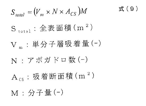
- the total surface area Stotal of the sample is determined by the formula (9), and the specific surface area S is determined by the formula (10) from the total surface area Stotal.
- the positive electrode active material total surface area per volume unit plate group i.e., the higher the product of the active material specific surface area and the active material weight is reactive species of the discharge reaction of hydrogen ions (H +) and sulfate ions (SO 4 2 - )
- H + hydrogen ions
- SO 4 2 - sulfate ions
- At least a carbonaceous conductive material and an organic compound that suppresses coarsening of the negative electrode active material due to charge / discharge are added to the negative electrode active material.
- the carbonaceous conductive material is preferably selected from a material group consisting of graphite, carbon black, activated carbon, carbon fiber, and carbon nanotube. Of these, graphite is preferable, and it is preferable to select scaly graphite as graphite. When using flaky graphite, the average primary particle diameter is preferably 100 ⁇ m or more.
- the amount of the carbonaceous conductive material added is in the range of 0.1 to 3 parts by mass with respect to 100 parts by mass of the fully charged negative electrode active material (sponge metal lead) (hereinafter simply referred to as “100 parts by mass of active material”). It is preferable to do this.
- the scale-like graphite refers to that described in JIS M-8601 (2005).
- the electrical resistivity of the scaly graphite is 0.02 ⁇ ⁇ cm or less, which is an order of magnitude less than about 0.1 ⁇ ⁇ cm of carbon blacks such as acetylene black. Therefore, by using scale-like graphite in place of the carbon blacks used in conventional lead-acid batteries, the electrical resistance of the negative electrode active material can be lowered and the charge acceptance performance can be improved.
- the average primary particle diameter of the scaly graphite is obtained according to the laser diffraction / scattering method described in JISM8511 (2005).
- a laser diffraction / scattering type particle size distribution analyzer for example, trade name Microtrac 9220FRA manufactured by Nikkiso Co., Ltd.
- a commercially available surfactant polyoxy as a dispersant is used.
- the obtained average particle diameter (median diameter: D50) is defined as the average primary particle diameter.
- Lead-acid batteries mounted on micro hybrid vehicles such as ISS cars and power generation control cars are used in a partially charged state called PSOC.
- PSOC a partially charged state
- the carbonaceous conductive material added to the negative electrode active material suppresses the coarsening of lead sulfate, maintains the lead sulfate in a fine state, suppresses the decrease in the concentration of lead ions dissolved from the lead sulfate, It acts to maintain a state with high charge acceptability.
- the organic compound that suppresses the coarsening of the negative electrode active material it is preferable to use bisphenols, aminobenzenesulfonic acid, and formaldehyde condensates.
- the bisphenols include bisphenol A, bisphenol F, and bisphenol S.
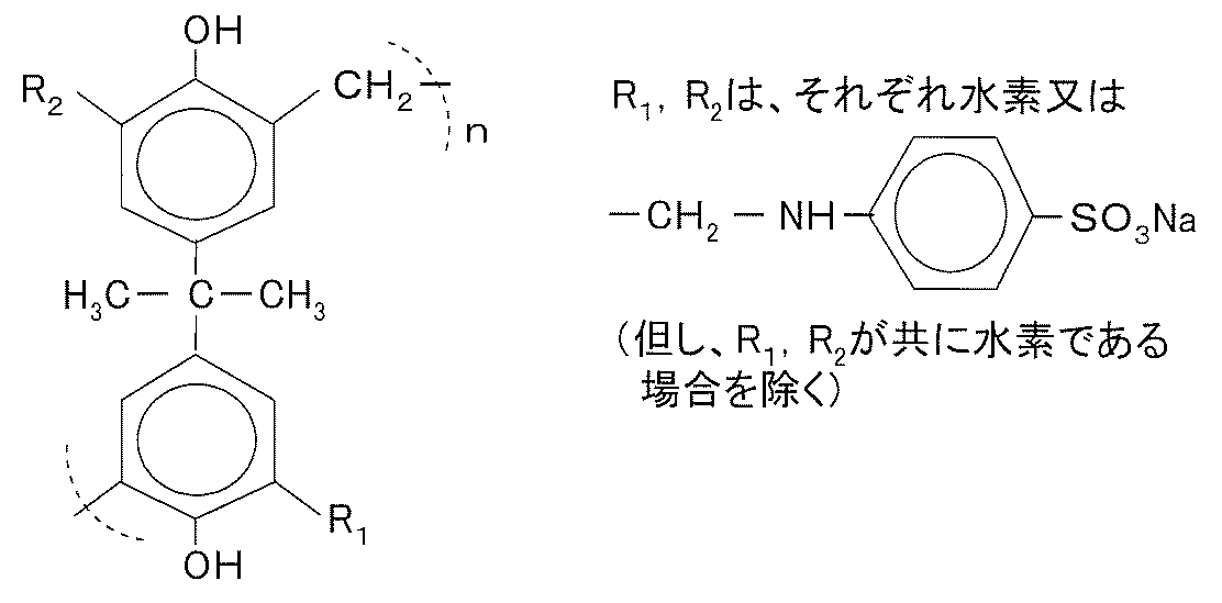
- the condensates a formaldehyde condensate of bisphenol A / aminobenzenesulfonic acid sodium salt represented by the chemical structural formula of [Chemical Formula 1] is particularly preferable.
- a particularly high effect can be obtained by using a condensate of a basic structural unit in which a p-aminobenzenesulfonic acid group is bonded to the benzene nucleus of a bisphenol, but using a condensate in which the sulfonic acid group is bonded to the benzene nucleus of a bisphenol. Can achieve the same effect.
- the charging reaction of the negative electrode active material depends on the concentration of lead ions dissolved from lead sulfate, which is a discharge product, and the charge acceptability increases as the amount of lead ions increases.
- Lignin which is widely used as an organic compound added to the negative electrode active material in order to suppress the coarsening of the negative electrode active material due to charge / discharge, decreases the reactivity of lead ions by adsorbing to lead ions, There is a side effect of inhibiting the charging reaction of the negative electrode active material and suppressing the improvement of charge acceptability.
- bisphenols, aminobenzenesulfonic acid and formaldehyde condensates having the chemical structural formula of [Chemical Formula 1] have a weak adsorption power to lead ions and a small amount of adsorption to lead ions. If the above condensate is used instead, the charge acceptability is hardly hindered, and the maintenance of the charge acceptability due to the addition of the carbonaceous conductive material is less likely to be hindered.
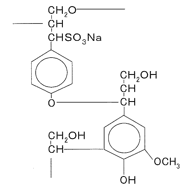
- the present invention prevents selection of sodium lignin sulfonate or the like represented by the chemical structural formula (partial structure) of [Chemical Formula 2] below as an organic compound that suppresses the coarsening of the negative electrode active material associated with charge and discharge. is not.
- sodium lignin sulfonate is frequently used as an organic compound that suppresses the coarsening of the negative electrode active material, it has a drawback that it has a strong adsorption power to lead ions and has a strong side effect of suppressing a charging reaction.
- bisphenols, aminobenzene sulfonic acid, and formaldehyde condensates have a weak adsorption capacity to lead ions and are less likely to be adsorbed by lead ions. Will not be disturbed.
- a normal polyethylene separator made of a polyethylene microporous sheet can be used as a separator.
- a polyethylene separator is not used alone, but glass fiber, polyolefin-based (polyethylene) It is preferable to use a separator made of a non-woven fabric made of fibers of materials such as fibers and pulp (simply referred to as “separator made of non-woven fabric”) and a polyethylene separator.
- a polyethylene separator and a non-woven fabric separator are overlapped and used so that the surface of the separator facing the negative electrode plate is constituted by the non-woven fabric separator.
- the separator made of a nonwoven fabric a separator made of a mixture of a plurality of fibers selected from the above-mentioned various materials may be used.
- the non-woven fabric made of a mixture of a plurality of fibers is not composed of glass fibers alone, such as a thin separator applied to a control valve type lead-acid battery disclosed in JP-A-2002-260714, for example. It is preferable to use a mixture of glass fibers and acid-resistant organic resin fibers, or a mixture of these mixtures with inorganic powders such as silica added to these mixtures as necessary.
- Non-woven fabric can be manufactured by dispersing the fiber in water and making it, so if the inorganic powder is dispersed in water together with the fiber during paper making, the inorganic powder can be easily contained in the nonwoven fabric. Can do.
- the charge acceptability of the entire battery can be further improved by combining the separator with the positive electrode plate described above. Can do. Further, by using this separator in combination with the positive electrode plate and the negative electrode plate described above, the charge acceptability of the entire lead storage battery can be greatly improved.
- Positive electrode plate An unchemically formed positive electrode plate was produced as follows. 0.1 mass% of cut fiber (short fiber of polyethylene terephthalate, the same applies hereinafter) was added to 1.0 kg of the raw material lead powder containing lead oxide as a main component, and mixed with a kneader. Next, water and dilute sulfuric acid having a specific gravity of 1.26 (converted to 20 ° C.) are dropped into the mixture of the raw material lead powder and the cut fiber and kneaded, and the water content is 14 mass% and the lead sulfate content is 15 mass%. A pasty positive electrode active material was prepared.
- the paste-like positive electrode active material was filled into a current collector made of a lead-calcium alloy lattice body in an amount of 67 kg, and then aged for 18 hours in an atmosphere at a temperature of 50 ° C. and a humidity of 95%. Thereafter, the positive electrode active material filled in the current collector was dried at a temperature of 60 ° C. for 16 hours to produce an unchemically formed positive electrode plate.
- Negative electrode plate An unformed negative electrode plate was prepared as follows. As an organic additive, (a) a bisphenol sulfonic acid polymer represented by the structural formula of (Chemical Formula 1) (molecular weight: 15,000 to 20,000, sulfur content in compound: 6 to 10% by mass) Got ready. 0.2 mass% of the bisphenol sulfonic acid polymer of the above (a) was blended and mixed with 1.0 kg of the raw material lead powder mainly composed of lead oxide. In this mixture, 1.0% by mass of carbon black powder (specific surface area 260 m 2 / g) using heavy oil as a raw material, 2.0% by mass of barium sulfate powder, and cut fiber 0.1% with respect to 1.0 kg of raw material lead powder.
- Mass% was added and mixed in a kneader to disperse the above-mentioned various blended materials in the raw material lead powder.
- Water and dilute sulfuric acid (specific gravity 1.26, converted to 20 ° C.) are dropped into the mixture thus obtained and kneaded, and a paste-like negative electrode active material having a water content of 12% by mass and a lead sulfate content of 13% by mass.
- the paste-like negative electrode active material was filled in a current collector made of a lead-calcium alloy lattice, and then aged for 18 hours in an atmosphere of a temperature of 50 ° C. and a humidity of 95%. Thereafter, the negative electrode active material filled in the current collector was dried to produce an unformed negative electrode plate.
- Negative electrodes A, B, and C shown below were prepared by using different organic compounds and carbonaceous conductive materials that suppress the coarsening of the negative electrode active material.
- Negative electrode plate A As the organic compound that suppresses the coarsening of the negative electrode active material, the organic compound mainly composed of sodium lignin sulfonate shown in the above [Chemical Formula 2] is selected, and carbon black using heavy oil as a raw material as a carbonaceous conductive material (ratio The surface area was 260 m 2 / g), and the amount added was 0.2 parts by mass with respect to 100 parts by mass of the active material.
- the negative electrode active material to which the organic compound and carbon black were added was filled in an expandable current collector to prepare a negative electrode plate A.
- Negative electrode plate B Formaldehyde condensate of bisphenol A / aminobenzenesulfonic acid sodium salt shown in [Chemical Formula 1] as an organic compound that suppresses the coarsening of the negative electrode active material (molecular weight: 17,000 to 20,000, sulfur content in the compound) 6 to 11% by mass) was selected as the main component, and the amount of carbon black added was 0.2 parts by mass with respect to 100 parts by mass of the active material.
- the negative electrode active material to which the organic compound and carbon black were added was filled in an expandable current collector to prepare a negative electrode plate B.
- Negative electrode plate C As an organic compound that suppresses the coarsening of the negative electrode active material, a formaldehyde condensate of bisphenol A and aminobenzenesulfonic acid sodium salt shown in [Chemical Formula 1] (molecular weight: 17,000 to 20,000, sulfur content in the compound) The main component is 6 to 11% by mass), scaly graphite (particle size: 180 ⁇ m) is used as the carbonaceous conductive material, and the amount added is 2 parts by mass with respect to 100 parts by mass of the active material. did. The negative electrode active material to which the organic compound and carbon black were added was filled in an expandable current collector to prepare a negative electrode plate C.
- the negative electrode plates A, B, and C, the positive electrode plate, and two types of separators were combined, and as an example, a B19 size lead-acid battery defined by the JIS standard was assembled.
- the battery is assembled by alternately laminating positive and negative plates through separators, and the total surface area of the positive plate per unit electrode plate group volume is 2.1 cm 2 / cm 3 (three positive plates and three negative plates).
- the electrode group volume of this lead storage battery was 325 [cm 3 ].
- the positive electrode plate and the negative electrode plate having the same size were used to form the electrode plate group. Therefore, the area of one side of the negative electrode current collector excluding the ear and the leg (width 10.1 [ cm] and height 11.1 [cm]) multiplied by 2.9 [cm] the thickness dimension of the electrode group in the state accommodated in the cell chamber (dimension measured in the stacking direction of the electrode plates). By performing the calculation, the electrode plate group volume was determined.
- separator P a separator using a polyethylene separator alone was designated as separator P
- separator Q a separator having a structure in which a nonwoven fabric made of glass fiber was arranged on the surface facing the negative electrode plate surface of the polyethylene separator was designated as separator Q.
- a glass fiber non-woven fabric was used as the non-woven fabric constituting the separator Q.
- a non-woven fabric made of fibers of a polyolefin-based material such as polyethylene or polypropylene, or a material of pulp or the like was used.
- a nonwoven fabric made of a mixture of fibers of these plural materials may be used.
- a nonwoven fabric made of a mixture of a plurality of fibers selected from the above-mentioned various materials is particularly preferable, but a nonwoven fabric having a configuration in which silica is further mixed into the mixture of these fibers is more preferable.
- the separator Q is configured by stacking a polyethylene separator and a nonwoven fabric made of glass fiber, but the separator Q may be configured only by a nonwoven fabric made of glass fiber or the like. That is, the separator Q may be any surface as long as the surface facing the negative electrode plate is made of a nonwoven fabric made of fibers of materials such as glass, polyolefin, and pulp.
- a battery case was formed.
- a dilute sulfuric acid having a specific gravity of 1.24 was injected into the battery case, and charged with an amount of electricity of 200% of the theoretical capacity based on the amount of active material charged to complete the lead acid battery.
- the characteristics and amount of the active material vary depending on the temperature at the time of chemical conversion, the current density, the specific gravity of the electrolyte, and the amount of lead sulfate contained in the paste.
- the specific surface area of the positive electrode active material can be decreased by increasing the chemical conversion temperature, and can be increased by increasing the specific gravity of the electrolyte.
- various lead storage batteries with different total positive electrode active material surface areas per unit electrode plate volume are prepared by adjusting the amount of active material according to the amount of lead sulfate contained in the paste and at the same time adjusting the temperature and electrolyte specific gravity at the time of battery formation. did. Adjustment of the total surface area of the positive electrode active material per unit electrode plate group volume is not limited to the amount of lead sulfate and chemical conversion conditions contained in the paste, for example, lead powder starting material, lead powder kneading conditions, electrode plate aging conditions, etc. It is realizable by selecting suitably.
- the total surface area of the positive electrode active material per unit electrode plate group volume is the product of the measured value of the specific surface area and the weight of the active material measured by the above-mentioned method after preparing a battery for active material property measurement, disassembling and taking out the positive electrode plate. was measured by a method of dividing this by the electrode group volume.
- NMR nuclear magnetic resonance
- the lead storage battery of Example 1 after chemical conversion was disassembled, and the negative electrode plate was taken out.
- the taken-out negative electrode plate was washed with water and the sulfuric acid content was washed away.
- the negative electrode active material after chemical conversion is porous metallic lead.
- the negative electrode plate was dried in an inert gas such as nitrogen.
- the negative electrode active material is separated from the dried negative electrode plate, pulverized, the pulverized product is put into a 10% sodium hydroxide solution, and the extracted liquid from which the generated precipitate (lead hydroxide) is removed is analyzed with the above apparatus. ⁇ It was measured.
- the measurement conditions are as shown in Table 1.
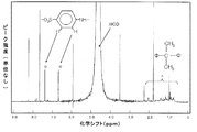
- FIG. 2 shows a spectrum measured by NMR spectroscopy.
- the horizontal axis indicates the chemical shift (ppm), and the vertical axis indicates the peak intensity.
- ppm chemical shift
- FIG. 2 with double circles p-aminobenzene, a formaldehyde condensate of bisphenol A / aminobenzenesulfonic acid sodium salt shown in [Chemical Formula 1], at chemical shifts of 6.7 ppm and 7.5 ppm. A peak derived from a sulfonic acid group was observed. Further, as indicated by a triangle in FIG.
- the charge acceptability was measured as follows. Adjust the SOC (charged state) to 90% of the fully charged state in a constant temperature bath at 25 ° C and apply 14V charging voltage (however, the current before reaching 14V is limited to 100A). ) The charging current value at 5 seconds from the start (5th charging current value) was measured. The higher the 5th second charging current value, the higher the initial charge acceptability.
- Cycle characteristics were measured as follows. Adjust the ambient temperature so that the battery temperature is 25 ° C, perform constant current discharge for 45A-59 seconds and 300A-1 seconds, then charge constant current / constant voltage for 100A-14V-60 seconds as one cycle.
- a life test was conducted. This test is a cycle test that simulates the use of lead-acid batteries in ISS cars. In this life test, since the amount of charge is small relative to the amount of discharge, the battery gradually becomes insufficient when charging is not performed completely. As a result, the voltage at the first second when the discharge current is 300 A for 1 second is obtained. Decrease gradually.
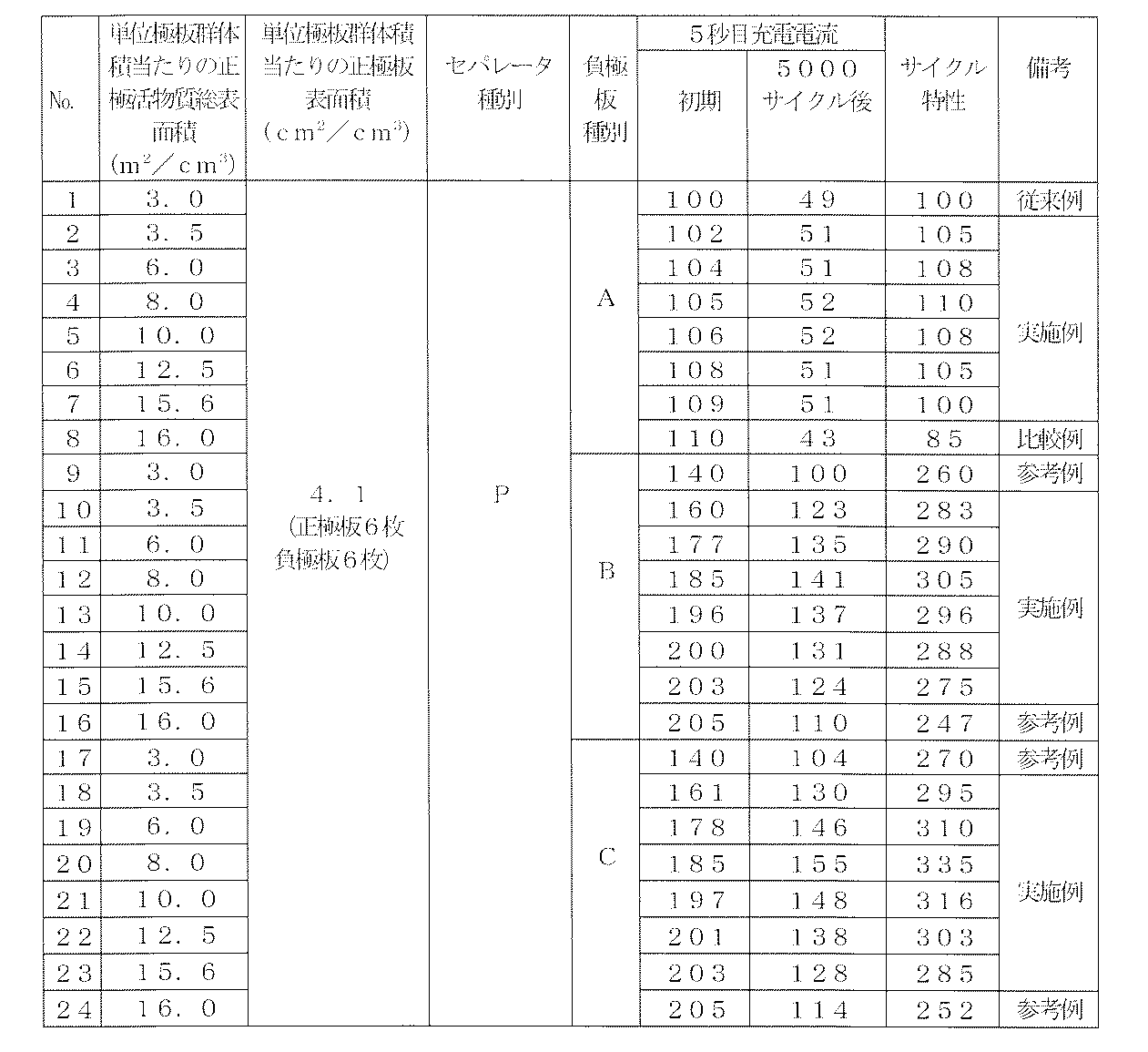
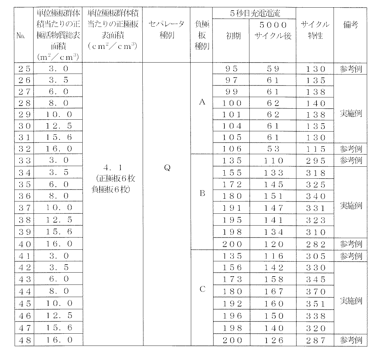
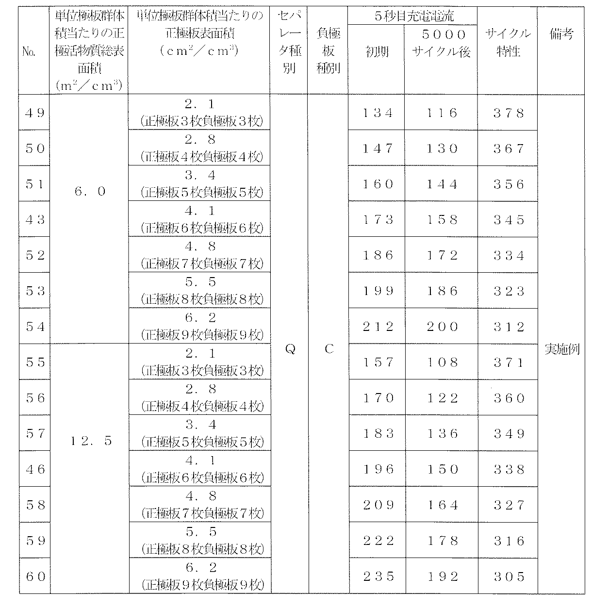
- Tables 2 and 3 show the measurement results of the charging current at the 5th second and the measurement results of the cycle characteristics, which were performed on the various lead storage batteries produced. The difference between Table 2 and Table 3 is only that the separators are different.
- the total surface area of the positive electrode active material per unit electrode plate group volume is 3.0 m 2 / cm 3 and the negative electrode plate A is combined as a conventional example, and the total surface area of the positive electrode active material per unit electrode plate group volume. was set to 16.0 m 2 / cm 3 as a comparative example.
- the total surface area of the positive electrode active material per unit electrode plate group volume was set to 3.0 or 16.0 m 2 / cm 3, and the case where the negative electrode plate B or C was combined was used as a reference example.
- Tables 2 and 3 show that the total surface area of the positive electrode plate per unit electrode plate group volume is fixed to 4.1 m 2 / cm 3 (six positive electrodes and six negative electrodes), and the positive electrode activity per unit electrode plate group volume.
- the thickness of the separator that is, the distance between adjacent electrode plates was set to a standard value of 0.8 mm. Even when the separator Q is used, the distance between the electrode plates does not increase as much as the glass mat is used together. The increase in thickness due to the combined use of the glass mat is absorbed, for example, by the ribs formed on the separator being deformed.
- the total surface area of the positive electrode active material per unit electrode plate group volume is set in the range of 3.5 to 15.6 m 2 / cm 3 .
- the charging current and cycle characteristics at the fifth second can be clearly improved as compared with the case of 2 / cm 3 .
- the charging current at 5 seconds continues to increase as the total surface area of the positive electrode active material per unit electrode plate group volume increases, but the cycle characteristic reaches a peak in the middle and starts to decrease.
- the total surface area of the positive electrode active material per unit electrode plate group volume is most preferably in the range of 3.5 to 15.6 m 2 / cm 3 .
- Scalar graphite is easy to increase because it has the characteristic that there is no change (curing) of paste properties even if the amount added is increased. In this embodiment, the case where 2 parts by mass of flaky graphite is added is shown.
- the charging current at the 5th second increases when the total surface area of the positive electrode plate per unit electrode plate group volume is increased, that is, the number of the electrode plates is increased.
- the cycle characteristics are in a conflicting relationship.
- the electrode plate group can be stored in a fixed volume battery case, and there is a limit in terms of the strength of the electrode plate even if the electrode plate is thinned and the number of electrode plates stored in the fixed volume battery case is increased. Therefore, it is usually difficult to set the total surface area of the positive electrode plate per unit electrode plate group volume to 6.2 cm 2 / cm 3 .
- the total positive electrode plate surface area per unit electrode plate group volume is preferably in the range of 2.8 to 5.5 cm 2 / cm 3 .
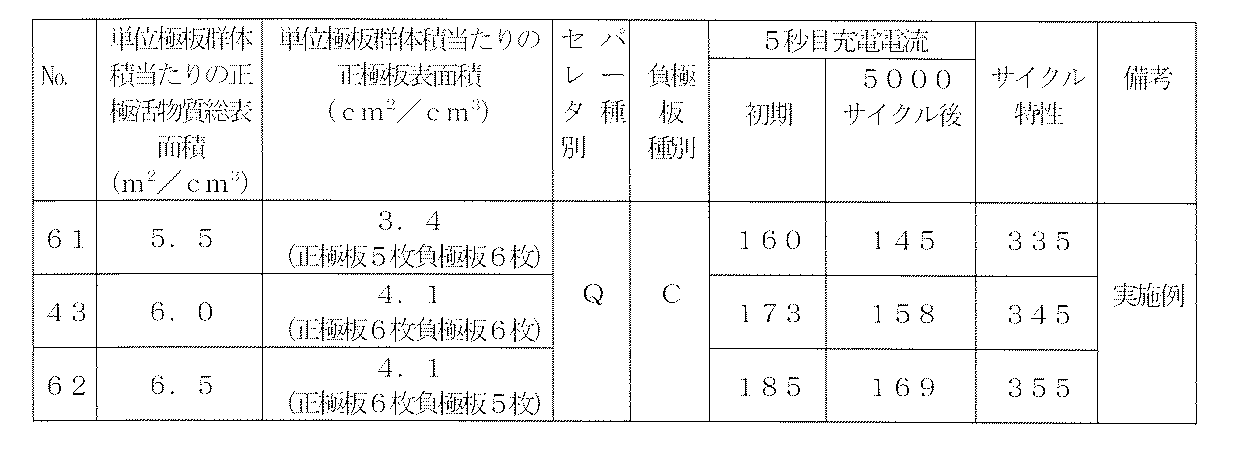
- Table 5 show the No. of the example (Table 3) where the number of positive and negative bipolar plates is the same. 43 shows the measurement result of the charging current at the 5th second and the measurement result of the cycle characteristics when one of the number of positive plates and the number of negative plates is larger than the other. is there.
- the thickness corresponding to the reduction of the total number of the electrode plates by one was allocated to the thickness of the positive and negative electrode plates and adjusted.
- the total surface area of the positive electrode active material per unit electrode plate group volume and the total surface area of the positive electrode plate per unit electrode plate group volume changed as shown in Table 5.
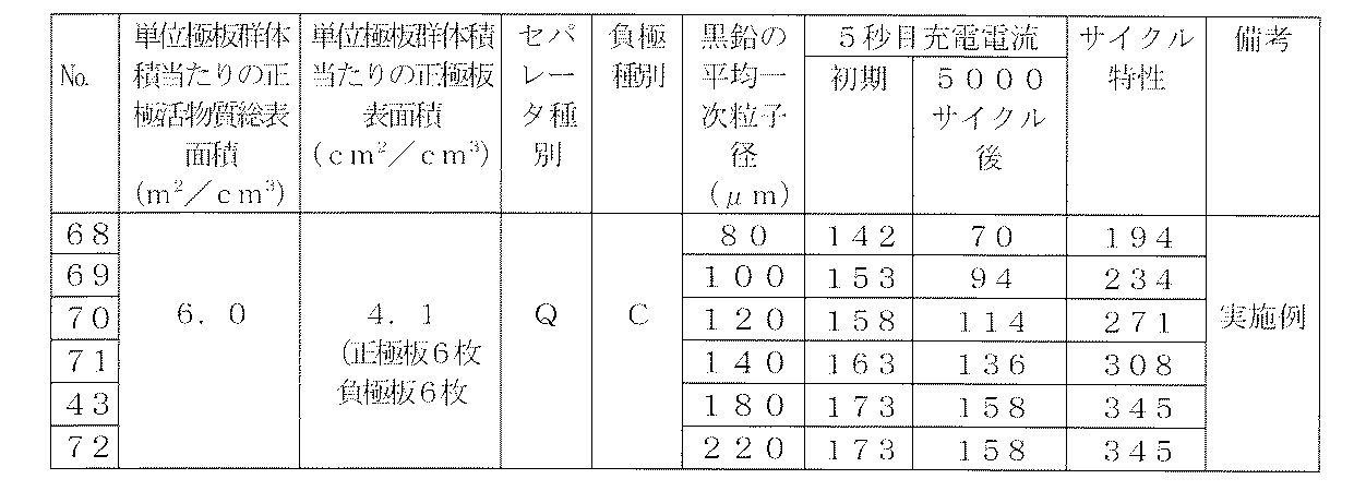
- the average primary particle size of the flake graphite is preferably in the range of 100 ⁇ m or more, and optimally 180 ⁇ m. An average primary particle diameter exceeding this is a natural product, so the production yield is poor and it is difficult to obtain.
- the charge acceptance was improved only by improving the characteristics of the negative electrode plate, but in the present invention, by increasing the value of the total surface area of the positive electrode active material per unit electrode plate group volume, The charge acceptability of the positive electrode plate was improved, thereby making it possible to further improve the charge acceptability of the whole battery as compared with the conventional battery, and enabling a further high rate discharge under PSOC.
- the present invention it is possible to improve the charge acceptability of the lead storage battery, so that it is possible to prevent repeated charge and discharge in a state of insufficient charge, so that discharge is generated by repeated charge and discharge in a state of insufficient charge. It is possible to prevent the lead sulfate, which is a product, from becoming coarse, and to improve the life performance of the lead storage battery under PSOC. This is a major advance for lead-acid batteries used under PSOC and greatly contributes to improving the performance of lead-acid batteries mounted on micro hybrid vehicles and the like.
- the present invention makes it possible to provide a liquid lead-acid battery with improved charge acceptability and lifetime performance under PSOC as compared with conventional micro hybrids such as ISS vehicles and power generation control vehicles. It contributes to the spread of cars. Therefore, the present invention is useful for solving the global problem of reducing carbon dioxide emission by improving the fuel efficiency of automobiles and suppressing global warming, and has great industrial applicability. .
Landscapes
- Chemical & Material Sciences (AREA)
- Chemical Kinetics & Catalysis (AREA)
- Electrochemistry (AREA)
- General Chemical & Material Sciences (AREA)
- Engineering & Computer Science (AREA)
- Manufacturing & Machinery (AREA)
- Power Engineering (AREA)
- Battery Electrode And Active Subsutance (AREA)
- Secondary Cells (AREA)
- Cell Separators (AREA)
Abstract
Description

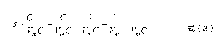
測定に用いる比表面積計では、吸着占有面積のわかったガス分子を試料に吸着させ、その吸着量(V)と相対圧力(P/Po)の関係を測定する。測定したVとP/Poより、式(2)の左辺とP/Poをプロットする。ここで、勾配をsとし、式(2)より式(3)を導く。
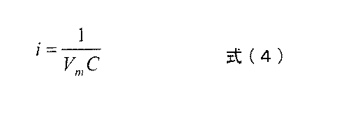
切片をiとすると、切片i、勾配sは、それぞれ式(4)、式(5)の通りとなる。式(4)及び式(5)を変形すると、それぞれ式(6)及び式(7)となり、単分子層吸着量Vmを求める式(8)が得られる。
すなわち、ある相対圧力P/Poにおける吸着量Vを数点測定し、プロットの傾きと切片を求めると、単分子層吸着量Vmが求まる。試料の全表面積Stotal は式(9)で求められ、比表面積Sは全表面積Stotal より式(10)で求められる。





次のようにして未化成の正極板を作製した。酸化鉛を主成分とする原料鉛粉1.0kgに対して、カットファイバ(ポリエチレンテレフタレートの短繊維、以下同じ。)を0.1質量%添加し、混練機にて混合した。次に、原料鉛粉とカットファイバとの混合物に水と比重1.26(20℃換算)の希硫酸とを滴下して混練し、水分含有量14質量%、硫酸鉛含有量15質量%のペースト状正極活物質を調製した。このペースト状の正極活物質を、鉛-カルシウム系合金の格子体からなる集電体に、1枚当たり67kg充填した後、温度50℃、湿度95%の雰囲気で18時間熟成させた。その後、集電体に充填された正極活物質を、温度60℃で16時間乾燥させて、未化成の正極板を作製した。
次のようにして未化成の負極板を作製した。有機添加剤として、前記(化1)の構造式で示される(a)ビスフェノールスルホン酸ポリマ(分子量:1.5万~2.0万、化合物中のイオウ含有量:6~10質量%)を準備した。酸化鉛を主成分とする原料鉛粉1.0kgに対して、上記(a)のビスフェノールスルホン酸ポリマを0.2質量%配合して混合した。この混合物に、原料鉛粉1.0kgに対して、重油を原料としたカーボンブラック粉末(比表面積260m2/g)1.0質量%、硫酸バリウム粉末2.0質量%、カットファイバ0.1質量%を添加し、混練機にて混合して上記の各種配合材を原料鉛粉中に分散させた。このようにして得られた混合物に水と希硫酸(比重1.26、20℃換算)を滴下して混練し、水分含有量12質量%、硫酸鉛含有量13質量%のペースト状負極活物質を調製した。このペースト状負極活物質を鉛-カルシウム系合金の格子体からなる集電体に充填した後、温度50℃、湿度95%の雰囲気で18時間の間熟成させた。その後、集電体に充填した負極活物質を乾燥させて、未化成の負極板を作製した。負極活物質の粗大化を抑制する有機化合物及び炭素質導電材を異ならせて、以下に示す負極板A,B,Cを作成した。
負極活物質の粗大化を抑制する有機化合物として、前記[化2]に示したリグニンスルホン酸ナトリウムを主成分とするものを選択し、炭素質導電材として、重油を原料としたカーボンブラック(比表面積260m2/g)を用い、その添加量を活物質100質量部に対し0.2質量部とした。上記有機化合物とカーボンブラックとを添加した負極活物質をエキスパンド式集電体に充填して負極板Aを作成した。
負極活物質の粗大化を抑制する有機化合物として[化1]に示したビスフェノールA・アミノベンゼンスルホン酸ナトリウム塩のホルムアルデヒド縮合物(分子量1.7万~2.0万,化合物中のイオウ含有量は6~11質量%)を主成分とするものを選択し、カーボンブラックの添加量を活物質100質量部に対し質0.2量部とした。上記有機化合物とカーボンブラックとを添加した負極活物質をエキスパンド式集電体に充填して負極板Bを作成した。
負極活物質の粗大化を抑制する有機化合物として、[化1]に示したビスフェノールA・アミノベンゼンスルホン酸ナトリウム塩のホルムアルデヒド縮合物(分子量1.7万~2.0万,化合物中のイオウ含有量は6~11質量%)を主成分とするものを選択し、炭素質導電材として、鱗片状黒鉛(粒径180μm)を用い、その添加量を活物質100質量部に対し2質量部とした。上記有機化合物とカーボンブラックとを添加した負極活物質をエキスパンド式集電体に充填して負極板Cを作成した。

この違いは、炭素質導電材の抵抗値がカーボンブラックよりも鱗片状黒鉛の方が低く、また鱗片状黒鉛の方が添加量を多くすることが出来るため、充電がより入りやすくなった結果と考えられる。
鱗片状黒鉛の平均一次粒子径を、80μm,100μm,120μm,140μm,180μm,220μmと変化させ、そのほかは表2のNo.19ならびに表3のNo.43のそれぞれのタイプの極板群構成と同様とした。5秒目充電電流とサイクル特性を評価した結果を、表6、7に示す。各表に示された5秒目充電電流及びサイクル特性は、表2の従来例を100(5秒目充電電流にあっては、初期を100)として評価したものである。

Claims (24)
- 負極活物質を負極集電体に充填してなる負極板と、正極活物質を正極集電体に充填してなる正極板とをセパレータを介して積層した極板群を、電解液とともに電槽内に収容した構成を有して、充電が間欠的に行われ、部分充電状態で負荷への高率放電が行われる液式鉛蓄電池であって、
少なくとも、炭素質導電材と、充放電に伴う負極活物質の粗大化を抑制する有機化合物とが前記負極活物質に添加され、
前記正極板は、単位極板群体積[cm3]当たりの正極活物質総表面積[m2]を、3.5ないし15.6[m2/cm3]の範囲とするように構成されていること、
を特徴とする鉛蓄電池。 - 前記正極板は、単位極板群体積[cm3]当たりの正極板総表面積[cm2]を2.8ないし5.5cm2/cm3の範囲とするように構成されていること、
を特徴とする請求項1に記載の鉛蓄電池。 - 前記充放電に伴う負極活物質の粗大化を抑制する有機化合物は、以下の化1の化学構造式で示されるビスフェノールA・アミノベンゼンスルホン酸・ホルムアルデヒド縮合物を主成分とする有機化合物である請求項1に記載の鉛蓄電池。

- 前記充放電に伴う負極活物質の粗大化を抑制する有機化合物は、以下の化1の化学構造式で示されるビスフェノールA・アミノベンゼンスルホン酸・ホルムアルデヒド縮合物を主成分とする有機化合物である請求項2に記載の鉛蓄電池。

- 前記炭素質導電材は、鱗片状黒鉛である請求項1に記載の鉛蓄電池。
- 前記炭素質導電材は、鱗片状黒鉛である請求項2に記載の鉛蓄電池。
- 前記炭素質導電材は、鱗片状黒鉛である請求項3に記載の鉛蓄電池。
- 前記炭素質導電材は、鱗片状黒鉛である請求項4に記載の鉛蓄電池。
- 前記鱗片状黒鉛は、平均一次粒子径が100μm以上である請求項5に記載の鉛蓄電池。
- 前記鱗片状黒鉛は、平均一次粒子径が100μm以上である請求項6に記載の鉛蓄電池。
- 前記鱗片状黒鉛は、平均一次粒子径が100μm以上である請求項7に記載の鉛蓄電池。
- 前記鱗片状黒鉛は、平均一次粒子径が100μm以上である請求項8に記載の鉛蓄電池。
- 前記セパレータは、前記負極板の表面に相対する表面が、ガラス、パルプ及びポリオレフィンからなる材料群から選択された少なくとも1つの材料の繊維で構成される不織布からなるように構成されている請求項1に記載の鉛蓄電池。
- 前記セパレータは、前記負極板の表面に相対する表面が、ガラス、パルプ及びポリオレフィンからなる材料群から選択された少なくとも1つの材料の繊維で構成される不織布からなるように構成されている請求項2に記載の鉛蓄電池。
- 前記セパレータは、前記負極板の表面に相対する表面が、ガラス、パルプ及びポリオレフィンからなる材料群から選択された少なくとも1つの材料の繊維で構成される不織布からなるように構成されている請求項3に記載の鉛蓄電池。
- 前記セパレータは、前記負極板の表面に相対する表面が、ガラス、パルプ及びポリオレフィンからなる材料群から選択された少なくとも1つの材料の繊維で構成される不織布からなるように構成されている請求項4に記載の鉛蓄電池。
- 前記セパレータは、前記負極板の表面に相対する表面が、ガラス、パルプ及びポリオレフィンからなる材料群から選択された少なくとも1つの材料の繊維で構成される不織布からなるように構成されている請求項5に記載の鉛蓄電池。
- 前記セパレータは、前記負極板の表面に相対する表面が、ガラス、パルプ及びポリオレフィンからなる材料群から選択された少なくとも1つの材料の繊維で構成される不織布からなるように構成されている請求項6に記載の鉛蓄電池。
- 前記セパレータは、前記負極板の表面に相対する表面が、ガラス、パルプ及びポリオレフィンからなる材料群から選択された少なくとも1つの材料の繊維で構成される不織布からなるように構成されている請求項7に記載の鉛蓄電池。
- 前記セパレータは、前記負極板の表面に相対する表面が、ガラス、パルプ及びポリオレフィンからなる材料群から選択された少なくとも1つの材料の繊維で構成される不織布からなるように構成されている請求項8に記載の鉛蓄電池。
- 前記セパレータは、前記負極板の表面に相対する表面が、ガラス、パルプ及びポリオレフィンからなる材料群から選択された少なくとも1つの材料の繊維で構成される不織布からなるように構成されている請求項9に記載の鉛蓄電池。
- 前記セパレータは、前記負極板の表面に相対する表面が、ガラス、パルプ及びポリオレフィンからなる材料群から選択された少なくとも1つの材料の繊維で構成される不織布からなるように構成されている請求項10に記載の鉛蓄電池。
- 前記セパレータは、前記負極板の表面に相対する表面が、ガラス、パルプ及びポリオレフィンからなる材料群から選択された少なくとも1つの材料の繊維で構成される不織布からなるように構成されている請求項11に記載の鉛蓄電池。
- 前記セパレータは、前記負極板の表面に相対する表面が、ガラス、パルプ及びポリオレフィンからなる材料群から選択された少なくとも1つの材料の繊維で構成される不織布からなるように構成されている請求項12に記載の鉛蓄電池。
Priority Applications (11)
| Application Number | Priority Date | Filing Date | Title |
|---|---|---|---|
| PH1/2012/502145A PH12012502145A1 (en) | 2010-05-10 | 2011-03-16 | Lead-acid battery |
| EP11780333.8A EP2571091B1 (en) | 2010-05-10 | 2011-03-16 | Lead storage battery |
| BR112012028803A BR112012028803A2 (pt) | 2010-05-10 | 2011-03-16 | bateria acumuladora de chumbo |
| AU2011251536A AU2011251536A1 (en) | 2010-05-10 | 2011-03-16 | Lead storage battery |
| US13/696,599 US20130099749A1 (en) | 2010-05-10 | 2011-03-16 | Lead-acid battery |
| EP17191158.9A EP3288107B1 (en) | 2010-05-10 | 2011-03-16 | Lead storage battery |
| RU2012153159/04A RU2533829C2 (ru) | 2010-05-10 | 2011-03-16 | Свинцово-кислотная аккумуляторная батарея |
| MX2012012944A MX2012012944A (es) | 2010-05-10 | 2011-03-16 | Bateria de plomo-acido. |
| KR1020127029401A KR20130062929A (ko) | 2010-05-10 | 2011-03-16 | 납 축전지 |
| CN201180023279.XA CN102893445B (zh) | 2010-05-10 | 2011-03-16 | 铅蓄电池 |
| JP2012514687A JP5783170B2 (ja) | 2010-05-10 | 2011-03-16 | 鉛蓄電池 |
Applications Claiming Priority (2)
| Application Number | Priority Date | Filing Date | Title |
|---|---|---|---|
| JP2010-108021 | 2010-05-10 | ||
| JP2010108021 | 2010-05-10 |
Publications (1)
| Publication Number | Publication Date |
|---|---|
| WO2011142072A1 true WO2011142072A1 (ja) | 2011-11-17 |
Family
ID=44914135
Family Applications (1)
| Application Number | Title | Priority Date | Filing Date |
|---|---|---|---|
| PCT/JP2011/001538 Ceased WO2011142072A1 (ja) | 2010-05-10 | 2011-03-16 | 鉛蓄電池 |
Country Status (11)
| Country | Link |
|---|---|
| US (1) | US20130099749A1 (ja) |
| EP (2) | EP3288107B1 (ja) |
| JP (1) | JP5783170B2 (ja) |
| KR (1) | KR20130062929A (ja) |
| CN (2) | CN108630900B (ja) |
| AU (1) | AU2011251536A1 (ja) |
| BR (1) | BR112012028803A2 (ja) |
| MX (1) | MX2012012944A (ja) |
| PH (1) | PH12012502145A1 (ja) |
| RU (1) | RU2533829C2 (ja) |
| WO (1) | WO2011142072A1 (ja) |
Cited By (23)
| Publication number | Priority date | Publication date | Assignee | Title |
|---|---|---|---|---|
| WO2013005733A1 (ja) * | 2011-07-05 | 2013-01-10 | 株式会社Gsユアサ | 液式鉛蓄電池 |
| WO2013058058A1 (ja) * | 2011-10-18 | 2013-04-25 | 新神戸電機株式会社 | 鉛蓄電池 |
| JPWO2011108175A1 (ja) * | 2010-03-02 | 2013-06-20 | 新神戸電機株式会社 | 鉛蓄電池 |
| JP2014123525A (ja) * | 2012-12-21 | 2014-07-03 | Gs Yuasa Corp | 鉛蓄電池用負極板及びその製造方法 |
| JPWO2013031263A1 (ja) * | 2011-09-01 | 2015-03-23 | 新神戸電機株式会社 | 鉛蓄電池 |
| JPWO2013073420A1 (ja) * | 2011-11-16 | 2015-04-02 | 新神戸電機株式会社 | 鉛蓄電池 |
| WO2015079631A1 (ja) * | 2013-11-29 | 2015-06-04 | 株式会社Gsユアサ | 鉛蓄電池 |
| JP2015225710A (ja) * | 2014-05-26 | 2015-12-14 | 新神戸電機株式会社 | 鉛蓄電池 |
| JP2016081736A (ja) * | 2014-10-17 | 2016-05-16 | 日立化成株式会社 | 鉛蓄電池 |
| JP2016119294A (ja) * | 2014-12-18 | 2016-06-30 | 株式会社Gsユアサ | 鉛蓄電池 |
| JP2016225113A (ja) * | 2015-05-29 | 2016-12-28 | 株式会社Gsユアサ | 鉛蓄電池 |
| JP2017004647A (ja) * | 2015-06-05 | 2017-01-05 | 日立化成株式会社 | 鉛蓄電池 |
| JP2017079166A (ja) * | 2015-10-21 | 2017-04-27 | 日立化成株式会社 | 鉛蓄電池 |
| WO2017099141A1 (ja) * | 2015-12-11 | 2017-06-15 | 日立化成株式会社 | 鉛蓄電池 |
| WO2017098665A1 (ja) * | 2015-12-11 | 2017-06-15 | 日立化成株式会社 | 鉛蓄電池 |
| JP2017174822A (ja) * | 2015-02-18 | 2017-09-28 | 株式会社Gsユアサ | 鉛蓄電池 |
| WO2017170422A1 (ja) * | 2016-03-30 | 2017-10-05 | 日立化成株式会社 | 鉛蓄電池、マイクロハイブリッド車及びアイドリングストップシステム車 |
| JP2018018798A (ja) * | 2016-07-29 | 2018-02-01 | 株式会社Gsユアサ | 鉛蓄電池 |
| JP2018018747A (ja) * | 2016-07-29 | 2018-02-01 | 株式会社Gsユアサ | 鉛蓄電池 |
| JP2018092959A (ja) * | 2018-03-27 | 2018-06-14 | 日立化成株式会社 | 鉛蓄電池 |
| US10003069B2 (en) | 2015-02-18 | 2018-06-19 | Gs Yuasa International Ltd. | Lead-acid battery |
| WO2019087683A1 (ja) | 2017-10-31 | 2019-05-09 | 株式会社Gsユアサ | 鉛蓄電池 |
| JP2019204801A (ja) * | 2019-09-04 | 2019-11-28 | 日立化成株式会社 | 鉛蓄電池 |
Families Citing this family (11)
| Publication number | Priority date | Publication date | Assignee | Title |
|---|---|---|---|---|
| JP5126454B2 (ja) | 2010-12-21 | 2013-01-23 | 新神戸電機株式会社 | 鉛蓄電池 |
| WO2015064445A1 (ja) * | 2013-10-28 | 2015-05-07 | 日立化成株式会社 | 樹脂組成物、電極、鉛蓄電池及びこれらの製造方法 |
| US9293748B1 (en) | 2014-09-15 | 2016-03-22 | Hollingsworth & Vose Company | Multi-region battery separators |
| EP3035433B1 (en) * | 2014-12-18 | 2020-02-19 | GS Yuasa International Ltd. | Lead-acid battery |
| US9786885B2 (en) | 2015-04-10 | 2017-10-10 | Hollingsworth & Vose Company | Battery separators comprising inorganic particles |
| CN104979561B (zh) * | 2015-05-23 | 2018-06-08 | 保定金阳光能源装备科技有限公司 | 一种石墨烯涂剂及该涂剂制作超级铅酸蓄电池负极板的制备方法 |
| CN108370032B (zh) * | 2015-10-06 | 2021-10-12 | 阿克爱科蒂夫有限公司 | 改进的铅酸蓄电池电极 |
| US20170302095A1 (en) * | 2016-04-18 | 2017-10-19 | Vitec Videocom Inc. | Smart charger with selective discharge capability |
| TWI829928B (zh) | 2019-05-31 | 2024-01-21 | 日商傑士湯淺國際股份有限公司 | 鉛蓄電池 |
| JP7505499B2 (ja) * | 2019-09-27 | 2024-06-25 | 株式会社Gsユアサ | 鉛蓄電池 |
| JP7424037B2 (ja) * | 2019-12-20 | 2024-01-30 | 株式会社Gsユアサ | 鉛蓄電池 |
Citations (14)
| Publication number | Priority date | Publication date | Assignee | Title |
|---|---|---|---|---|
| JPH0676815A (ja) * | 1992-06-29 | 1994-03-18 | Shin Kobe Electric Mach Co Ltd | 鉛蓄電池用陽極板及びその製造方法 |
| JPH07201331A (ja) | 1993-12-29 | 1995-08-04 | Japan Storage Battery Co Ltd | 密閉形鉛蓄電池 |
| JPH1040907A (ja) | 1996-07-29 | 1998-02-13 | Shin Kobe Electric Mach Co Ltd | 鉛蓄電池用正極板の製造法 |
| JPH11250913A (ja) | 1998-03-02 | 1999-09-17 | Aisin Seiki Co Ltd | 鉛蓄電池 |
| JP2000208143A (ja) * | 1999-01-14 | 2000-07-28 | Shin Kobe Electric Mach Co Ltd | 鉛蓄電池及びその製造方法 |
| JP2002141066A (ja) * | 2000-10-31 | 2002-05-17 | Shin Kobe Electric Mach Co Ltd | 制御弁式鉛蓄電池 |
| JP2002231247A (ja) * | 2001-01-30 | 2002-08-16 | Shin Kobe Electric Mach Co Ltd | 制御弁式鉛蓄電池 |
| JP2002260714A (ja) | 2001-03-01 | 2002-09-13 | Matsushita Electric Ind Co Ltd | 制御弁式鉛蓄電池 |
| JP2003036882A (ja) | 2001-07-19 | 2003-02-07 | Furukawa Battery Co Ltd:The | シール型鉛蓄電池 |
| JP2003051306A (ja) | 2001-08-07 | 2003-02-21 | Furukawa Battery Co Ltd:The | 鉛蓄電池用負極 |
| WO2005124920A1 (ja) * | 2004-06-16 | 2005-12-29 | Matsushita Electric Industrial Co., Ltd. | 鉛蓄電池 |
| JP2006196191A (ja) | 2005-01-11 | 2006-07-27 | Shin Kobe Electric Mach Co Ltd | 鉛蓄電池 |
| JP2007026753A (ja) * | 2005-07-13 | 2007-02-01 | Matsushita Electric Ind Co Ltd | 鉛蓄電池 |
| JP2009104914A (ja) * | 2007-10-24 | 2009-05-14 | Panasonic Corp | 鉛蓄電池 |
Family Cites Families (13)
| Publication number | Priority date | Publication date | Assignee | Title |
|---|---|---|---|---|
| JPS6091572A (ja) * | 1983-10-24 | 1985-05-22 | Yuasa Battery Co Ltd | 密閉形鉛蓄電池 |
| JPH0362452A (ja) * | 1989-07-31 | 1991-03-18 | Shin Kobe Electric Mach Co Ltd | 鉛蓄電池の製造方法 |
| WO1997037393A1 (fr) * | 1996-03-29 | 1997-10-09 | Aisin Seiki Kabushiki Kaisha | Accumulateur au plomb |
| JPH09306497A (ja) * | 1996-05-20 | 1997-11-28 | Japan Storage Battery Co Ltd | 鉛蓄電池用負極板 |
| JP3374665B2 (ja) * | 1996-07-23 | 2003-02-10 | 松下電器産業株式会社 | 密閉型鉛蓄電池 |
| AU2002218953A1 (en) * | 2000-12-14 | 2002-06-24 | Avansys Power Co., Ltd. | An environmental protection type of valve-regulated lead-acid storage battery |
| JP2003092098A (ja) * | 2001-09-17 | 2003-03-28 | Shin Kobe Electric Mach Co Ltd | 鉛蓄電池 |
| JP4501330B2 (ja) * | 2002-05-24 | 2010-07-14 | パナソニック株式会社 | 鉛蓄電池 |
| JP2005050608A (ja) * | 2003-07-31 | 2005-02-24 | Sumitomo Bakelite Co Ltd | 燃料電池セパレーターの製造方法 |
| JP4332783B2 (ja) * | 2003-09-25 | 2009-09-16 | 株式会社ジーエス・ユアサコーポレーション | 密閉形鉛蓄電池 |
| JP4812257B2 (ja) * | 2004-01-30 | 2011-11-09 | 古河電池株式会社 | サイクルユース用密閉型鉛蓄電池 |
| CN101202355A (zh) * | 2006-12-15 | 2008-06-18 | 夏振明 | 电动汽车用长寿命高容量双极型极板铅酸电池 |
| US8637183B2 (en) * | 2007-06-06 | 2014-01-28 | Hammond Group, Inc. | Expanders for lead-acid batteries |
-
2011
- 2011-03-16 EP EP17191158.9A patent/EP3288107B1/en active Active
- 2011-03-16 US US13/696,599 patent/US20130099749A1/en not_active Abandoned
- 2011-03-16 CN CN201810325275.0A patent/CN108630900B/zh not_active Expired - Fee Related
- 2011-03-16 RU RU2012153159/04A patent/RU2533829C2/ru not_active IP Right Cessation
- 2011-03-16 AU AU2011251536A patent/AU2011251536A1/en not_active Abandoned
- 2011-03-16 CN CN201180023279.XA patent/CN102893445B/zh active Active
- 2011-03-16 BR BR112012028803A patent/BR112012028803A2/pt not_active IP Right Cessation
- 2011-03-16 EP EP11780333.8A patent/EP2571091B1/en active Active
- 2011-03-16 JP JP2012514687A patent/JP5783170B2/ja active Active
- 2011-03-16 KR KR1020127029401A patent/KR20130062929A/ko not_active Withdrawn
- 2011-03-16 WO PCT/JP2011/001538 patent/WO2011142072A1/ja not_active Ceased
- 2011-03-16 MX MX2012012944A patent/MX2012012944A/es unknown
- 2011-03-16 PH PH1/2012/502145A patent/PH12012502145A1/en unknown
Patent Citations (14)
| Publication number | Priority date | Publication date | Assignee | Title |
|---|---|---|---|---|
| JPH0676815A (ja) * | 1992-06-29 | 1994-03-18 | Shin Kobe Electric Mach Co Ltd | 鉛蓄電池用陽極板及びその製造方法 |
| JPH07201331A (ja) | 1993-12-29 | 1995-08-04 | Japan Storage Battery Co Ltd | 密閉形鉛蓄電池 |
| JPH1040907A (ja) | 1996-07-29 | 1998-02-13 | Shin Kobe Electric Mach Co Ltd | 鉛蓄電池用正極板の製造法 |
| JPH11250913A (ja) | 1998-03-02 | 1999-09-17 | Aisin Seiki Co Ltd | 鉛蓄電池 |
| JP2000208143A (ja) * | 1999-01-14 | 2000-07-28 | Shin Kobe Electric Mach Co Ltd | 鉛蓄電池及びその製造方法 |
| JP2002141066A (ja) * | 2000-10-31 | 2002-05-17 | Shin Kobe Electric Mach Co Ltd | 制御弁式鉛蓄電池 |
| JP2002231247A (ja) * | 2001-01-30 | 2002-08-16 | Shin Kobe Electric Mach Co Ltd | 制御弁式鉛蓄電池 |
| JP2002260714A (ja) | 2001-03-01 | 2002-09-13 | Matsushita Electric Ind Co Ltd | 制御弁式鉛蓄電池 |
| JP2003036882A (ja) | 2001-07-19 | 2003-02-07 | Furukawa Battery Co Ltd:The | シール型鉛蓄電池 |
| JP2003051306A (ja) | 2001-08-07 | 2003-02-21 | Furukawa Battery Co Ltd:The | 鉛蓄電池用負極 |
| WO2005124920A1 (ja) * | 2004-06-16 | 2005-12-29 | Matsushita Electric Industrial Co., Ltd. | 鉛蓄電池 |
| JP2006196191A (ja) | 2005-01-11 | 2006-07-27 | Shin Kobe Electric Mach Co Ltd | 鉛蓄電池 |
| JP2007026753A (ja) * | 2005-07-13 | 2007-02-01 | Matsushita Electric Ind Co Ltd | 鉛蓄電池 |
| JP2009104914A (ja) * | 2007-10-24 | 2009-05-14 | Panasonic Corp | 鉛蓄電池 |
Non-Patent Citations (3)
| Title |
|---|
| JIS M, 2005, pages 8511 |
| JIS M, 2005, pages 8601 |
| See also references of EP2571091A4 |
Cited By (33)
| Publication number | Priority date | Publication date | Assignee | Title |
|---|---|---|---|---|
| JPWO2011108175A1 (ja) * | 2010-03-02 | 2013-06-20 | 新神戸電機株式会社 | 鉛蓄電池 |
| WO2013005733A1 (ja) * | 2011-07-05 | 2013-01-10 | 株式会社Gsユアサ | 液式鉛蓄電池 |
| JPWO2013031263A1 (ja) * | 2011-09-01 | 2015-03-23 | 新神戸電機株式会社 | 鉛蓄電池 |
| WO2013058058A1 (ja) * | 2011-10-18 | 2013-04-25 | 新神戸電機株式会社 | 鉛蓄電池 |
| JPWO2013058058A1 (ja) * | 2011-10-18 | 2015-04-02 | 新神戸電機株式会社 | 鉛蓄電池 |
| JPWO2013073420A1 (ja) * | 2011-11-16 | 2015-04-02 | 新神戸電機株式会社 | 鉛蓄電池 |
| JP2014123525A (ja) * | 2012-12-21 | 2014-07-03 | Gs Yuasa Corp | 鉛蓄電池用負極板及びその製造方法 |
| JPWO2015079631A1 (ja) * | 2013-11-29 | 2017-03-16 | 株式会社Gsユアサ | 鉛蓄電池 |
| WO2015079631A1 (ja) * | 2013-11-29 | 2015-06-04 | 株式会社Gsユアサ | 鉛蓄電池 |
| US10096862B2 (en) | 2013-11-29 | 2018-10-09 | Gs Yuasa International Ltd. | Lead-acid battery |
| JP2015225710A (ja) * | 2014-05-26 | 2015-12-14 | 新神戸電機株式会社 | 鉛蓄電池 |
| JP2016081736A (ja) * | 2014-10-17 | 2016-05-16 | 日立化成株式会社 | 鉛蓄電池 |
| JP2016119294A (ja) * | 2014-12-18 | 2016-06-30 | 株式会社Gsユアサ | 鉛蓄電池 |
| JP2017174822A (ja) * | 2015-02-18 | 2017-09-28 | 株式会社Gsユアサ | 鉛蓄電池 |
| US10003069B2 (en) | 2015-02-18 | 2018-06-19 | Gs Yuasa International Ltd. | Lead-acid battery |
| JP2016225113A (ja) * | 2015-05-29 | 2016-12-28 | 株式会社Gsユアサ | 鉛蓄電池 |
| JP2017004647A (ja) * | 2015-06-05 | 2017-01-05 | 日立化成株式会社 | 鉛蓄電池 |
| JP2017079166A (ja) * | 2015-10-21 | 2017-04-27 | 日立化成株式会社 | 鉛蓄電池 |
| WO2017098665A1 (ja) * | 2015-12-11 | 2017-06-15 | 日立化成株式会社 | 鉛蓄電池 |
| JP2018139230A (ja) * | 2015-12-11 | 2018-09-06 | 日立化成株式会社 | 鉛蓄電池 |
| JP2018170285A (ja) * | 2015-12-11 | 2018-11-01 | 日立化成株式会社 | 鉛蓄電池 |
| WO2017099141A1 (ja) * | 2015-12-11 | 2017-06-15 | 日立化成株式会社 | 鉛蓄電池 |
| WO2017099144A1 (ja) * | 2015-12-11 | 2017-06-15 | 日立化成株式会社 | 鉛蓄電池 |
| JPWO2017099144A1 (ja) * | 2015-12-11 | 2018-06-07 | 日立化成株式会社 | 鉛蓄電池 |
| JPWO2017099141A1 (ja) * | 2015-12-11 | 2018-07-12 | 日立化成株式会社 | 鉛蓄電池 |
| WO2017098666A1 (ja) * | 2015-12-11 | 2017-06-15 | 日立化成株式会社 | 鉛蓄電池 |
| JPWO2017170422A1 (ja) * | 2016-03-30 | 2018-08-02 | 日立化成株式会社 | 鉛蓄電池、マイクロハイブリッド車及びアイドリングストップシステム車 |
| WO2017170422A1 (ja) * | 2016-03-30 | 2017-10-05 | 日立化成株式会社 | 鉛蓄電池、マイクロハイブリッド車及びアイドリングストップシステム車 |
| JP2018018747A (ja) * | 2016-07-29 | 2018-02-01 | 株式会社Gsユアサ | 鉛蓄電池 |
| JP2018018798A (ja) * | 2016-07-29 | 2018-02-01 | 株式会社Gsユアサ | 鉛蓄電池 |
| WO2019087683A1 (ja) | 2017-10-31 | 2019-05-09 | 株式会社Gsユアサ | 鉛蓄電池 |
| JP2018092959A (ja) * | 2018-03-27 | 2018-06-14 | 日立化成株式会社 | 鉛蓄電池 |
| JP2019204801A (ja) * | 2019-09-04 | 2019-11-28 | 日立化成株式会社 | 鉛蓄電池 |
Also Published As
| Publication number | Publication date |
|---|---|
| BR112012028803A2 (pt) | 2016-07-26 |
| MX2012012944A (es) | 2012-12-17 |
| EP3288107B1 (en) | 2019-02-20 |
| KR20130062929A (ko) | 2013-06-13 |
| JP5783170B2 (ja) | 2015-09-24 |
| CN102893445A (zh) | 2013-01-23 |
| CN108630900A (zh) | 2018-10-09 |
| JPWO2011142072A1 (ja) | 2013-07-22 |
| CN102893445B (zh) | 2018-05-15 |
| EP2571091A1 (en) | 2013-03-20 |
| CN108630900B (zh) | 2021-11-09 |
| EP3288107A1 (en) | 2018-02-28 |
| US20130099749A1 (en) | 2013-04-25 |
| PH12012502145A1 (en) | 2013-01-07 |
| EP2571091A4 (en) | 2016-03-02 |
| EP2571091B1 (en) | 2017-11-29 |
| RU2533829C2 (ru) | 2014-11-20 |
| RU2012153159A (ru) | 2014-06-20 |
| AU2011251536A1 (en) | 2012-12-20 |
Similar Documents
| Publication | Publication Date | Title |
|---|---|---|
| JP5783170B2 (ja) | 鉛蓄電池 | |
| JP5621841B2 (ja) | 鉛蓄電池 | |
| JP5598532B2 (ja) | 鉛蓄電池 | |
| JP5500315B2 (ja) | 鉛蓄電池 | |
| JP5083481B2 (ja) | 鉛蓄電池 | |
| JP6597842B2 (ja) | 鉛蓄電池 | |
| JPWO2016084858A1 (ja) | 鉛蓄電池 | |
| JP2013065443A (ja) | 鉛蓄電池 |
Legal Events
| Date | Code | Title | Description |
|---|---|---|---|
| WWE | Wipo information: entry into national phase |
Ref document number: 201180023279.X Country of ref document: CN |
|
| 121 | Ep: the epo has been informed by wipo that ep was designated in this application |
Ref document number: 11780333 Country of ref document: EP Kind code of ref document: A1 |
|
| WWE | Wipo information: entry into national phase |
Ref document number: 12012502145 Country of ref document: PH |
|
| WWE | Wipo information: entry into national phase |
Ref document number: MX/A/2012/012944 Country of ref document: MX |
|
| ENP | Entry into the national phase |
Ref document number: 20127029401 Country of ref document: KR Kind code of ref document: A |
|
| WWE | Wipo information: entry into national phase |
Ref document number: 2012514687 Country of ref document: JP |
|
| WWE | Wipo information: entry into national phase |
Ref document number: 1201005865 Country of ref document: TH |
|
| NENP | Non-entry into the national phase |
Ref country code: DE |
|
| WWE | Wipo information: entry into national phase |
Ref document number: 10495/DELNP/2012 Country of ref document: IN |
|
| REEP | Request for entry into the european phase |
Ref document number: 2011780333 Country of ref document: EP |
|
| WWE | Wipo information: entry into national phase |
Ref document number: 2011780333 Country of ref document: EP |
|
| ENP | Entry into the national phase |
Ref document number: 2012153159 Country of ref document: RU Kind code of ref document: A |
|
| ENP | Entry into the national phase |
Ref document number: 2011251536 Country of ref document: AU Date of ref document: 20110316 Kind code of ref document: A |
|
| WWE | Wipo information: entry into national phase |
Ref document number: 13696599 Country of ref document: US |
|
| REG | Reference to national code |
Ref country code: BR Ref legal event code: B01A Ref document number: 112012028803 Country of ref document: BR |
|
| ENP | Entry into the national phase |
Ref document number: 112012028803 Country of ref document: BR Kind code of ref document: A2 Effective date: 20121109 |