WO2012017507A1 - Carte de circuit imprimé et son procédé de fabrication - Google Patents
Carte de circuit imprimé et son procédé de fabrication Download PDFInfo
- Publication number
- WO2012017507A1 WO2012017507A1 PCT/JP2010/007354 JP2010007354W WO2012017507A1 WO 2012017507 A1 WO2012017507 A1 WO 2012017507A1 JP 2010007354 W JP2010007354 W JP 2010007354W WO 2012017507 A1 WO2012017507 A1 WO 2012017507A1
- Authority
- WO
- WIPO (PCT)
- Prior art keywords
- circuit board
- lands
- land
- semiconductor device
- printed circuit
- Prior art date
- Legal status (The legal status is an assumption and is not a legal conclusion. Google has not performed a legal analysis and makes no representation as to the accuracy of the status listed.)
- Ceased
Links
Images



Classifications
-
- H—ELECTRICITY
- H05—ELECTRIC TECHNIQUES NOT OTHERWISE PROVIDED FOR
- H05K—PRINTED CIRCUITS; CASINGS OR CONSTRUCTIONAL DETAILS OF ELECTRIC APPARATUS; MANUFACTURE OF ASSEMBLAGES OF ELECTRICAL COMPONENTS
- H05K1/00—Printed circuits
- H05K1/02—Details
- H05K1/0296—Conductive pattern lay-out details not covered by sub groups H05K1/02 - H05K1/0295
-
- H—ELECTRICITY
- H05—ELECTRIC TECHNIQUES NOT OTHERWISE PROVIDED FOR
- H05K—PRINTED CIRCUITS; CASINGS OR CONSTRUCTIONAL DETAILS OF ELECTRIC APPARATUS; MANUFACTURE OF ASSEMBLAGES OF ELECTRICAL COMPONENTS
- H05K1/00—Printed circuits
- H05K1/02—Details
- H05K1/11—Printed elements for providing electric connections to or between printed circuits
- H05K1/111—Pads for surface mounting, e.g. lay-out
-
- H—ELECTRICITY
- H10—SEMICONDUCTOR DEVICES; ELECTRIC SOLID-STATE DEVICES NOT OTHERWISE PROVIDED FOR
- H10W—GENERIC PACKAGES, INTERCONNECTIONS, CONNECTORS OR OTHER CONSTRUCTIONAL DETAILS OF DEVICES COVERED BY CLASS H10
- H10W70/00—Package substrates; Interposers; Redistribution layers [RDL]
- H10W70/60—Insulating or insulated package substrates; Interposers; Redistribution layers
- H10W70/62—Insulating or insulated package substrates; Interposers; Redistribution layers characterised by their interconnections
- H10W70/65—Shapes or dispositions of interconnections
-
- H—ELECTRICITY
- H10—SEMICONDUCTOR DEVICES; ELECTRIC SOLID-STATE DEVICES NOT OTHERWISE PROVIDED FOR
- H10W—GENERIC PACKAGES, INTERCONNECTIONS, CONNECTORS OR OTHER CONSTRUCTIONAL DETAILS OF DEVICES COVERED BY CLASS H10
- H10W90/00—Package configurations
- H10W90/701—Package configurations characterised by the relative positions of pads or connectors relative to package parts
-
- H—ELECTRICITY
- H05—ELECTRIC TECHNIQUES NOT OTHERWISE PROVIDED FOR
- H05K—PRINTED CIRCUITS; CASINGS OR CONSTRUCTIONAL DETAILS OF ELECTRIC APPARATUS; MANUFACTURE OF ASSEMBLAGES OF ELECTRICAL COMPONENTS
- H05K2201/00—Indexing scheme relating to printed circuits covered by H05K1/00
- H05K2201/09—Shape and layout
- H05K2201/09209—Shape and layout details of conductors
- H05K2201/09654—Shape and layout details of conductors covering at least two types of conductors provided for in H05K2201/09218 - H05K2201/095
- H05K2201/09781—Dummy conductors, i.e. not used for normal transport of current; Dummy electrodes of components
-
- H—ELECTRICITY
- H05—ELECTRIC TECHNIQUES NOT OTHERWISE PROVIDED FOR
- H05K—PRINTED CIRCUITS; CASINGS OR CONSTRUCTIONAL DETAILS OF ELECTRIC APPARATUS; MANUFACTURE OF ASSEMBLAGES OF ELECTRICAL COMPONENTS
- H05K3/00—Apparatus or processes for manufacturing printed circuits
- H05K3/30—Assembling printed circuits with electric components, e.g. with resistors
- H05K3/32—Assembling printed circuits with electric components, e.g. with resistors electrically connecting electric components or wires to printed circuits
- H05K3/34—Assembling printed circuits with electric components, e.g. with resistors electrically connecting electric components or wires to printed circuits by soldering
- H05K3/341—Surface mounted components
- H05K3/3431—Leadless components
- H05K3/3436—Leadless components having an array of bottom contacts, e.g. pad grid array or ball grid array components
-
- H—ELECTRICITY
- H10—SEMICONDUCTOR DEVICES; ELECTRIC SOLID-STATE DEVICES NOT OTHERWISE PROVIDED FOR
- H10W—GENERIC PACKAGES, INTERCONNECTIONS, CONNECTORS OR OTHER CONSTRUCTIONAL DETAILS OF DEVICES COVERED BY CLASS H10
- H10W70/00—Package substrates; Interposers; Redistribution layers [RDL]
- H10W70/60—Insulating or insulated package substrates; Interposers; Redistribution layers
- H10W70/62—Insulating or insulated package substrates; Interposers; Redistribution layers characterised by their interconnections
- H10W70/65—Shapes or dispositions of interconnections
- H10W70/654—Top-view layouts
- H10W70/656—Fan-in layouts
-
- H—ELECTRICITY
- H10—SEMICONDUCTOR DEVICES; ELECTRIC SOLID-STATE DEVICES NOT OTHERWISE PROVIDED FOR
- H10W—GENERIC PACKAGES, INTERCONNECTIONS, CONNECTORS OR OTHER CONSTRUCTIONAL DETAILS OF DEVICES COVERED BY CLASS H10
- H10W74/00—Encapsulations, e.g. protective coatings
-
- H—ELECTRICITY
- H10—SEMICONDUCTOR DEVICES; ELECTRIC SOLID-STATE DEVICES NOT OTHERWISE PROVIDED FOR
- H10W—GENERIC PACKAGES, INTERCONNECTIONS, CONNECTORS OR OTHER CONSTRUCTIONAL DETAILS OF DEVICES COVERED BY CLASS H10
- H10W90/00—Package configurations
- H10W90/701—Package configurations characterised by the relative positions of pads or connectors relative to package parts
- H10W90/751—Package configurations characterised by the relative positions of pads or connectors relative to package parts of bond wires
- H10W90/754—Package configurations characterised by the relative positions of pads or connectors relative to package parts of bond wires between a chip and a stacked insulating package substrate, interposer or RDL
-
- Y—GENERAL TAGGING OF NEW TECHNOLOGICAL DEVELOPMENTS; GENERAL TAGGING OF CROSS-SECTIONAL TECHNOLOGIES SPANNING OVER SEVERAL SECTIONS OF THE IPC; TECHNICAL SUBJECTS COVERED BY FORMER USPC CROSS-REFERENCE ART COLLECTIONS [XRACs] AND DIGESTS
- Y02—TECHNOLOGIES OR APPLICATIONS FOR MITIGATION OR ADAPTATION AGAINST CLIMATE CHANGE
- Y02P—CLIMATE CHANGE MITIGATION TECHNOLOGIES IN THE PRODUCTION OR PROCESSING OF GOODS
- Y02P70/00—Climate change mitigation technologies in the production process for final industrial or consumer products
- Y02P70/50—Manufacturing or production processes characterised by the final manufactured product
Definitions
- the present invention relates to a circuit board including a semiconductor device and a printed board, and a method for manufacturing the circuit board.
- circuit boards including a printed circuit board and a semiconductor device mounted on the printed circuit board are used in electronic devices such as mobile phones, personal computers, and video equipment.
- array packages such as BGA (Ball Grid Array) type and LGA (Land Grid Array) type CSP (Chip size package) are widely known.
- Such a semiconductor device has a plurality of device-side lands that are mechanically connected to a printed circuit board via solder.
- a plurality of device-side lands may be arranged asymmetrically (see, for example, Patent Document 1 and Patent Document 2).
- the present invention has been made to solve the above-described problems, and an object thereof is to provide a circuit board capable of suppressing soldering defects and a method for manufacturing the circuit board.
- a circuit board includes a printed circuit board and a plurality of device-side lands arranged asymmetrically with respect to a predetermined reference point, and a semiconductor device mounted on the printed circuit board. Includes a plurality of device-side connection lands that are mechanically connected to the printed circuit board via solder, and a device-side separation land that is mechanically separated from the printed circuit board.
- circuit board capable of suppressing soldering defects and a method for manufacturing the circuit board.
- FIG. 1 is a plan view of a semiconductor device 20 according to an embodiment. 1 is a plan view of a semiconductor device 20 according to an embodiment. It is sectional drawing in the XX line of FIG. It is a top view of circuit board 100 concerning an embodiment. It is sectional drawing in the YY line
- FIG. 1 is a plan view of the printed circuit board 10 according to the embodiment as viewed from the mounting surface 10S side.
- the printed circuit board 10 includes a substrate body 11 and a plurality of substrate-side lands 12.
- the substrate body 11 is a plate-like member made of paper phenol or glass epoxy.
- the substrate body 11 has a mounting surface 10S.
- On the mounting surface 10S electronic components (for example, a CPU, a resistor, a capacitor, etc.) not shown are mounted.
- the semiconductor device 20 is mounted on the mounting surface 10S.
- the plurality of substrate-side lands 12 are terminals for mounting the semiconductor device 20.
- the plurality of board-side lands 12 are provided on the mounting surface 10S.
- the plurality of substrate-side lands 12 are made of, for example, copper foil.
- the plurality of board-side lands 12 are arranged asymmetrically with respect to a predetermined reference point A in a plan view of the mounting surface 10S. That is, the arrangement of the plurality of substrate-side lands 12 is not point-symmetric.
- the predetermined reference point A is, for example, the center point of the entire plurality of substrate-side lands 12.
- the plurality of substrate-side lands 12 include 45 substrate-side connection lands 12a and four substrate-side separation lands 12b.
- Each board-side connection land 12a is mechanically connected to the semiconductor device 20 via a connection portion 30 (see FIG. 5) described later.
- Each substrate-side separation land 12 b is mechanically separated from the semiconductor device 20.
- the 45 substrate-side connection lands 12 a which are a part of the plurality of substrate-side lands 12 contribute to the bonding of the semiconductor device 20, whereas the four substrate-side separated lands 12 b are formed on the semiconductor device 20. Does not contribute to joining.
- substrate side separation land 12b have the same structure.
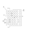
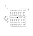
- FIG. 2 is a plan view of the semiconductor device 20 according to the embodiment as viewed from the facing surface 20S side.
- FIG. 3 is a plan view of the semiconductor device 20 from which the plurality of solder balls 22 are omitted, as viewed from the facing surface 20S side.
- 4 is a cross-sectional view taken along line XX of FIG. As shown in FIG.
- the semiconductor device 20 includes a package substrate 21 and a plurality of solder balls 22.
- an array package such as BGA (Ball Grid Array) type or LGA (Land Grid Array) type CSP (Chip size package) can be used.
- the package substrate 21 is a plate-like member made of an insulating material.
- the package substrate 21 has a facing surface 20S that faces the mounting surface 10S.
- the plurality of solder balls 22 are spherical members provided on the facing surface 20S.
- the plurality of solder balls 22 are made of solder (for example, an alloy of Sn3Ag0.5Cu (Ag is 3 wt%, Cu is 0.5 wt%, and the rest is Sn)).
- the plurality of solder balls 22 are arranged asymmetrically with reference to an intersection B between the perpendicular surface perpendicular to the opposing surface 20S and passing through the center of gravity of the semiconductor device 20 and the opposing surface 20S.
- the intersection point B passes through the approximate center of the facing surface 20S.
- the plurality of solder balls 22 include 45 connection balls 22a and 4 separation balls 22b.
- Each connection ball 22a mechanically connects the printed circuit board 10 and the semiconductor device 20 by constituting a part of the connection portion 30 (see FIG. 5) when the semiconductor device 20 is mounted. Since each separation ball 22b does not constitute a part of the connection portion 30 when the semiconductor device 20 is mounted, the printed circuit board 10 and the semiconductor device 20 are not mechanically connected.
- the 45 connection balls 22 a which are a part of the plurality of solder balls 22 contribute to the bonding of the semiconductor device 20, whereas the four separation balls 22 b do not contribute to the bonding of the semiconductor device 20.
- each connection ball 22a and each separation ball 22b have the same configuration.
- the semiconductor device 20 has a plurality of device-side lands 23.
- the plurality of device-side lands 23 are arranged asymmetrically with respect to the intersection B.
- the plurality of device-side lands 23 include 42 real lands 23R and seven dummy lands 23D.
- the 42 real lands 23R are mechanically connected to the printed circuit board via the connection portion 30 (see FIG. 5) when the semiconductor device 20 is mounted.
- Each real land 23R is electrically connected to a semiconductor element 24 (see FIG. 4) disposed in the semiconductor device 20. Accordingly, each real land 23 ⁇ / b> R contributes to the function of the semiconductor device 20.
- the 42 real lands 23R include a plurality of signal terminals, a plurality of power supply terminals, a plurality of grounding terminals, and the like.
- the seven dummy lands 23D are electrically separated from the semiconductor element 24 (see FIG. 4). Therefore, each dummy land 23 ⁇ / b> D does not contribute to the function of the semiconductor device 20.
- the seven dummy lands 23D include three first dummy lands 23D 1 and four second dummy lands 23D 2 .
- the first dummy land 23D 1 is mechanically connected to the printed circuit board via the connection portion 30 in the same manner as the 42 real lands 23R.
- the second dummy land 23D 2 is different from the first dummy land 23D 1, mechanically separated from the printed circuit board.
- 42 pieces of real land 23R and the three first dummy land 23D 1 each is connected to each board connection lands 12a.
- 42 pieces of real land 23R and the three first dummy land 23D 1 of constitutes "device-side connection land" to placed 45 corresponding to 45 of the board-side connection lands 12a.
- each second dummy land 23D 2 is disposed at a distance from the four substrate side spaced lands 12b.
- each second dummy land 23D 2 constitutes a “device-side separation land” that does not contribute to the function of the semiconductor device 20 and does not contribute to the bonding between the printed circuit board 10 and the semiconductor device 20.
- the second dummy land 23D 2 is appropriately referred to as “device-side separation land”.
- the semiconductor device 20 includes a semiconductor element 24, a first insertion wiring 25, a second insertion wiring 26, a wire 27, an electrode portion 28, and an exterior body 29.
- the semiconductor element 24 is an active element such as a transistor or an integrated circuit.
- the semiconductor element 24 is electrically connected to the electrode portion 28 of the package substrate 21 through the wire 27.
- One real land 23 ⁇ / b> R is electrically connected to the electrode portion 28 via the first insertion wiring 25.
- Another real land 23 ⁇ / b> R is electrically connected to the electrode portion 28 via the second interpolated wiring 26.
- the semiconductor element 24 is electrically connected to the two real lands 23R.
- the three first dummy lands 23D 1 and the two second dummy lands 23D 2 are electrically separated from the semiconductor element 24.
- FIG. 5 is a plan view of the circuit board 100 according to the embodiment as viewed from the mounting surface 10S side. 6 is a cross-sectional view taken along line YY of FIG. In FIG. 5, the 45 connecting portions 30 are indicated by broken lines, and the four spacing balls 22b are omitted. As shown in FIG. 5, the semiconductor device 20 is mounted on the printed circuit board 10 via 45 connection portions 30.
- connection portions 30 are disposed asymmetrically with respect to a perpendicular C passing through the center of gravity of the semiconductor device 20 and perpendicular to the mounting surface 10S.
- the perpendicular C passes through the intersection B.
- the plurality of device-side lands 23 include a plurality of device-side connection lands that are mechanically connected to the printed circuit board via the connection portion 30.
- seven device side land 23 shown includes five two real land 23R and the three first dummy land 23D 1 of the to be board-side connecting lands 12a and mechanically connected .
- the plurality of device-side lands 23 include device-side separation lands that are mechanically separated from the printed circuit board 10.
- seven device side land 23 shown includes a second dummy land 23D 2 mechanically separated from the two board-side spaced lands 12b.
- connecting portion 30 is mechanically connected to the board-side connecting lands 12a and real land 23R or first dummy land 23D 1.
- the connection portion 30 is formed by fusing the connection balls 22a with the cream solder 40 applied on the board-side connection lands 12a.
- the separation balls 22b maintain the original shape without forming the connection portions 30. Therefore, the separation ball 22b is separated from the substrate-side separation land 12b.
- the interval W between each device-side connection land (each real land 23R and the first dummy land 23D 1 ) and the printed board 10 (each board-side land 12) is uniform.
- the facing surface 20S is substantially parallel to the mounting surface 10S. That is, the semiconductor device 20 is not inclined with respect to the printed circuit board 10.
- cream solder 40 is applied on 45 substrate-side connection lands 12 a that are a part of the plurality of substrate-side lands 12 provided on the printed circuit board 10. At this time, the cream solder 40 is not applied on the four board-side separated lands 12b.
- a plurality of target lands (hereinafter referred to as “a plurality of target lands”) to which the cream solder 40 is to be applied are plural so that the semiconductor device 20 does not tilt with the solidification of the fusion body 30a described later.
- the device-side land 23 is selected.
- the fusion body 30a attempts to rotate the semiconductor device 20.
- the fusion body 30a attempts to rotate the semiconductor device 20.
- only the second dummy land 23D 2 among the plurality of apparatus-side lands 23 are excluded from the plurality of target lands.
- the semiconductor device 20 is placed on the printed circuit board 10 to which the cream solder 40 is applied.
- the lower end portion of each connection ball 22a is in contact with the cream solder 40 applied on each substrate-side connection land 12a.
- the cream solder 40 is not applied to each substrate-side separated land 12b, the lower end portion of each separated ball 22b does not contact the cream solder 40.
- the lower end portion of each separation ball 22b may be in contact with each substrate-side separation land 12b.
- the printed circuit board 10 and the semiconductor device 20 are placed in a heating device such as a reflow furnace, and the solder balls 22 are heated to the melting point or higher.
- the 45 connection balls 22a and the cream solder 40 are fused to form 45 fusion bodies 30a.
- the four spacing balls 22b melt, the cream solder 40 is not applied to the four board-side spacing lands 12b, so that the spacing balls 22b do not fuse with the cream solder 40.
- each fusion body 30a tends to be rounded by surface tension when it is liquefied by melting, and tends to shrink when solidified, so that each device-side connection land is printed by each fusion body 30a. Pulled to the plate 10 side.
- the semiconductor device 20 is subjected to a moment of tensile force by the 45 fusion bodies 30a.
- the cream solder 40 is applied only to a plurality of target lands selected from the plurality of device-side lands 23. Therefore, since the moment applied to the semiconductor device 20 is balanced, the inclination of the semiconductor device 20 is suppressed.
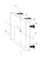
- FIG. 8 is a diagram schematically showing a moment applied to the semiconductor device 20 when the fusion body 30a is melted and solidified. Such a moment is generated according to the moment generated according to the surface tension of the melted fusion body 30a (the force by which the fusion body 30a tries to be small and round) and the contraction force when the fusion body 30a is solidified. Two types of moments are assumed: moments.
- the axis Q 1 passes through the center of gravity P of the semiconductor device 20 and is parallel to the facing surface 20S.
- the axis Q 2 passes through the center of gravity P of the semiconductor device 20, is parallel to the facing surface 20 S, and is perpendicular to the axis Q 1 . As shown in FIG.
- the semiconductor device 20 if a reference axis Q 1, is under the resultant moment M1 and resultant moment M2. Further, when the axis Q 2 is used as a reference, the semiconductor device 20 is applied with the resultant moment M3 and the resultant moment M4.
- the plurality of target lands are selected, for example, so that the combined moment M1 and the combined moment M2 are balanced, and the combined moment M3 and the combined moment M4 are balanced.
- the inclination of the semiconductor device 20 accompanying the melting and solidification of the 45 fusion bodies 30a is suppressed.
- the precision which suppresses the inclination of the semiconductor device 20 improves, so that many reference
- the semiconductor device 20 includes a plurality of device-side lands 23 that are asymmetrically arranged with respect to the intersection B.
- the plurality of device-side lands 23 include 45 device-side connecting lands (42 real lands 23R and three first dummy lands 23D 1 ) and four device-side separated lands (four second dummy lands). 23D 2 ).
- Each device-side connection land is mechanically connected to the printed circuit board 10 via the connection unit 30.
- Each device-side separation land is mechanically separated from the printed circuit board 10.
- the present inventors diligently investigated the cause of the occurrence of cracks in the vicinity of the boundaries between a plurality of device-side lands and solder, and found that the molten solder tried to be rounded by surface tension and the solder solidified. I got the knowledge that it was caused by the force to try to contract when doing. Specifically, for example, if all of the plurality of device-side lands 23 arranged asymmetrically are soldered to the plurality of board-side lands 12, the surface tension of the melted solder and the shrinkage force of the solidified solder are many. It becomes large in the area where the device-side lands 23 are densely packed. As described above, the semiconductor device 20 is inclined with respect to the printed circuit board 10 due to an unbalanced force acting on the semiconductor device 20.
- the circuit board 100 only the first dummy land 23D 1 of the dummy lands 23D is mechanically connected to the printed circuit board 10, and the second dummy land 23D 2 is mechanically connected to the printed circuit board 10. Not connected to. Therefore, compared with the case where all of the dummy lands 23D are mechanically joined to the printed circuit board 10, the surface tension and solidification shrinkage force of the solder are suppressed from being concentrated on a part of the semiconductor device 20. Thereby, since the inclination of the semiconductor device 20 is suppressed, generation
- the intervals between the plurality of device-side lands 23 and the printed circuit board 10 are uniform.
- the height of each of the plurality of connection portions 30 is formed uniformly, for example, the strength of each connection portion 30 is higher than when only a part of the plurality of connection portions 30 is formed elongated. Uniformity can be achieved.
- the facing surface 20S is substantially parallel to the mounting surface 10S.
- the strength of each connection portion 30 can be made uniform.
- the four device-side separation lands (four second dummy lands 23D 2 ) are electrically separated from the semiconductor element 24. As described above, the land that does not originally contribute to the function of the semiconductor device 20 is mechanically separated from the semiconductor device 10. Therefore, the function of the semiconductor device 20 is not deteriorated.
- the method for manufacturing the circuit board 100 includes a step of applying the cream solder 40 onto the 45 substrate-side connection lands 12a that are a part of the plurality of substrate-side lands 12.
- the cream solder 40 is applied only to the 45 substrate-side connection lands 12 a, only 45 device-side connection lands among the plurality of device-side lands 23 are mechanically connected to the printed circuit board 10. Therefore, compared with the case where all of the plurality of device-side lands 23 are mechanically bonded to the printed circuit board 10, it is possible to suppress the concentration of the solder surface tension and solidification contraction force on a part of the semiconductor device 20. As a result, since the semiconductor device 20 can be prevented from tilting, the occurrence of cracks and the like in the connection portion 30 can be reduced.
- the 45 device-side connection lands are arranged asymmetrically with respect to the intersection point B, but may be arranged symmetrically with respect to the intersection point B. In this case, it is possible to balance the moment of force that each device-side connection land is pulled toward the printed circuit board 10 via the connection portion 30 with higher accuracy.
- the four device side spaced lands although the electrically be connected not a four second dummy land 23D 2 in the semiconductor element 24 is not limited thereto.
- the four device-side separated lands may be selected from the real lands 23 ⁇ / b> R electrically connected to the semiconductor element 24.
- the real land 23R as the four device-side separated lands, a part of a plurality of signal terminals, a part of a plurality of power supply terminals, a part of a plurality of grounding terminals for transmitting the same signal repeatedly. It is preferred that some are selected.
- the plurality of device-side lands 23 include 42 real lands 23R, three first dummy lands 23D 1 , and four second dummy lands 23D 2 .
- the number of each land is not limited to this.
- the case where the plurality of device-side lands 23 include one second dummy land 23D 2 is, for example, a plurality of devices arranged in n ⁇ m rows in order to cause the transfer robot to automatically determine the orientation of the semiconductor device 20.
- the transfer robot to automatically determine the orientation of the semiconductor device 20.
- each separation ball 22b is physically (mechanically and electrically) separated from each substrate-side separation land 12b as shown in FIG. is not.
- Each separation ball 22b may be electrically connected to each substrate-side separation land 12b. That is, each separation ball 22b is not mechanically joined to each substrate-side separation land 12b, and is allowed to contact.
- the second dummy land 23D 2 is because it is electrically separated from the semiconductor element 24, there is no effect on the function of the semiconductor device 20.
- the interval W between each device-side connection land and the printed circuit board 10 is uniform. However, the present invention is not limited to this.
- the interval W between each device-side connection land and the printed circuit board 10 may vary within a predetermined range.
- the predetermined range can be set to such an extent that no cracks are generated in the connection portion 30. Further, as long as this is the case, the facing surface 20S may not be completely parallel to the mounting surface 10S.
- the device-side separated land is mechanically separated from the substrate-side separated land 12b by not applying the cream solder 40 to the substrate-side separated land 12b.
- the present invention is not limited to this. Absent.
- the apparatus-side separation land can be mechanically separated from the substrate-side separation land 12b by not providing the separation balls 22b on the apparatus-side separation land.
- the present invention naturally includes various embodiments not described herein. Therefore, the technical scope of the present invention is defined only by the invention specifying matters according to the scope of claims reasonable from the above description.
- circuit board capable of suppressing soldering defects and a manufacturing method thereof, which is useful in the field of electronic equipment.
Landscapes
- Engineering & Computer Science (AREA)
- Microelectronics & Electronic Packaging (AREA)
- Electric Connection Of Electric Components To Printed Circuits (AREA)
- Wire Bonding (AREA)
- Semiconductor Integrated Circuits (AREA)
- Design And Manufacture Of Integrated Circuits (AREA)
- Physics & Mathematics (AREA)
- Geometry (AREA)
Abstract
Priority Applications (3)
| Application Number | Priority Date | Filing Date | Title |
|---|---|---|---|
| US13/809,186 US9198284B2 (en) | 2010-08-06 | 2010-12-20 | Circuit board and method for manufacturing same |
| JP2012527480A JP5870303B2 (ja) | 2010-08-06 | 2010-12-20 | 回路基板及びその製造方法 |
| CN201080067544.XA CN102959699B (zh) | 2010-08-06 | 2010-12-20 | 电路基板及其制造方法 |
Applications Claiming Priority (2)
| Application Number | Priority Date | Filing Date | Title |
|---|---|---|---|
| JP2010176990 | 2010-08-06 | ||
| JP2010-176990 | 2010-08-06 |
Publications (1)
| Publication Number | Publication Date |
|---|---|
| WO2012017507A1 true WO2012017507A1 (fr) | 2012-02-09 |
Family
ID=45559039
Family Applications (1)
| Application Number | Title | Priority Date | Filing Date |
|---|---|---|---|
| PCT/JP2010/007354 Ceased WO2012017507A1 (fr) | 2010-08-06 | 2010-12-20 | Carte de circuit imprimé et son procédé de fabrication |
Country Status (4)
| Country | Link |
|---|---|
| US (1) | US9198284B2 (fr) |
| JP (1) | JP5870303B2 (fr) |
| CN (1) | CN102959699B (fr) |
| WO (1) | WO2012017507A1 (fr) |
Cited By (2)
| Publication number | Priority date | Publication date | Assignee | Title |
|---|---|---|---|---|
| JP2016502262A (ja) * | 2012-12-21 | 2016-01-21 | ▲華▼▲為▼終端有限公司Huawei Device Co., Ltd. | 電子装置及びランド・グリッド・アレイモジュール |
| US20230067845A1 (en) * | 2021-08-30 | 2023-03-02 | International Business Machines Corporation | Creating a standoff for a low-profile component without adding a process step |
Families Citing this family (8)
| Publication number | Priority date | Publication date | Assignee | Title |
|---|---|---|---|---|
| US9171798B2 (en) * | 2013-01-25 | 2015-10-27 | Taiwan Semiconductor Manufacturing Company, Ltd. | Methods and apparatus for transmission lines in packages |
| ES2565548B1 (es) * | 2014-09-03 | 2017-01-25 | Ontech Security, Sl | Sensor de campos electrostáticos y sistema de seguridad en ambientes industriales |
| KR102339899B1 (ko) * | 2014-12-12 | 2021-12-15 | 삼성전자주식회사 | 반도체 패키지, 모듈 기판 및 이를 포함하는 반도체 패키지 모듈 |
| KR102377472B1 (ko) * | 2015-03-10 | 2022-03-23 | 삼성전자주식회사 | 반도체 패키지 및 그 제조방법 |
| WO2019024058A1 (fr) * | 2017-08-03 | 2019-02-07 | 华为技术有限公司 | Module d'emballage de matrice de pastilles et terminal |
| CN108711272A (zh) * | 2018-05-28 | 2018-10-26 | 上海理工大学 | 一种基于NB-IoT的物体倾覆预警系统 |
| KR102785620B1 (ko) | 2020-06-15 | 2025-03-26 | 삼성전자주식회사 | 인쇄 회로 기판을 포함하는 전자 장치 |
| CN116056321B (zh) * | 2022-08-05 | 2023-10-20 | 荣耀终端有限公司 | 电路板、电路板组件和电子设备 |
Citations (4)
| Publication number | Priority date | Publication date | Assignee | Title |
|---|---|---|---|---|
| JP2003110055A (ja) * | 2001-09-28 | 2003-04-11 | Mitsumi Electric Co Ltd | 表面実装型半導体パッケージ |
| JP2004063761A (ja) * | 2002-07-29 | 2004-02-26 | Nec Electronics Corp | 半導体装置 |
| JP2005108996A (ja) * | 2003-09-29 | 2005-04-21 | Seiko Epson Corp | パッケージic、実装構造体、実装構造体を搭載した電気光学装置、および電気光学装置を搭載した電子機器 |
| JP2008172060A (ja) * | 2007-01-12 | 2008-07-24 | Oki Electric Ind Co Ltd | 半導体装置及びその製造方法 |
Family Cites Families (36)
| Publication number | Priority date | Publication date | Assignee | Title |
|---|---|---|---|---|
| US3458925A (en) * | 1966-01-20 | 1969-08-05 | Ibm | Method of forming solder mounds on substrates |
| US3871014A (en) * | 1969-08-14 | 1975-03-11 | Ibm | Flip chip module with non-uniform solder wettable areas on the substrate |
| US5157480A (en) * | 1991-02-06 | 1992-10-20 | Motorola, Inc. | Semiconductor device having dual electrical contact sites |
| US5186383A (en) * | 1991-10-02 | 1993-02-16 | Motorola, Inc. | Method for forming solder bump interconnections to a solder-plated circuit trace |
| US5269453A (en) * | 1992-04-02 | 1993-12-14 | Motorola, Inc. | Low temperature method for forming solder bump interconnections to a plated circuit trace |
| US5465152A (en) * | 1994-06-03 | 1995-11-07 | Robotic Vision Systems, Inc. | Method for coplanarity inspection of package or substrate warpage for ball grid arrays, column arrays, and similar structures |
| TW303427B (fr) * | 1994-06-10 | 1997-04-21 | Sony Co Ltd | |
| JP3310499B2 (ja) * | 1995-08-01 | 2002-08-05 | 富士通株式会社 | 半導体装置 |
| US5726502A (en) * | 1996-04-26 | 1998-03-10 | Motorola, Inc. | Bumped semiconductor device with alignment features and method for making the same |
| JPH09306954A (ja) * | 1996-05-20 | 1997-11-28 | Hitachi Ltd | 半導体装置及びその実装方法並びに実装構造体 |
| US5859474A (en) * | 1997-04-23 | 1999-01-12 | Lsi Logic Corporation | Reflow ball grid array assembly |
| JPH1174407A (ja) * | 1997-08-29 | 1999-03-16 | Mitsubishi Electric Corp | 半導体装置 |
| JPH11132737A (ja) | 1997-10-29 | 1999-05-21 | Juki Corp | 画像処理方法 |
| GB2344550A (en) * | 1998-12-09 | 2000-06-14 | Ibm | Pad design for electronic package |
| JP3437107B2 (ja) | 1999-01-27 | 2003-08-18 | シャープ株式会社 | 樹脂封止型半導体装置 |
| US6222277B1 (en) * | 1999-06-23 | 2001-04-24 | Emc Corporation | Non-collapsing interconnection for semiconductor devices |
| US6781245B2 (en) * | 2001-01-08 | 2004-08-24 | Siliconware Precision Industries Co., Ltd. | Array structure of solder balls able to control collapse |
| JP2003100801A (ja) * | 2001-09-25 | 2003-04-04 | Mitsubishi Electric Corp | 半導体装置 |
| JP3978369B2 (ja) * | 2002-05-20 | 2007-09-19 | アルプス電気株式会社 | 高周波モジュールの取付構造 |
| CN100472770C (zh) * | 2003-01-30 | 2009-03-25 | 高通股份有限公司 | 具有未电连接的焊锡球的区域阵列封装件 |
| US6762495B1 (en) | 2003-01-30 | 2004-07-13 | Qualcomm Incorporated | Area array package with non-electrically connected solder balls |
| DE10341206A1 (de) * | 2003-09-04 | 2005-04-14 | Infineon Technologies Ag | Anordnung zur Verbesserung der Zuverlässigkeit von BGA-Lötverbindungen |
| JP2005166794A (ja) * | 2003-12-01 | 2005-06-23 | Ricoh Co Ltd | 部品パッケージとプリント配線基板および電子機器 |
| US7109583B2 (en) * | 2004-05-06 | 2006-09-19 | Endwave Corporation | Mounting with auxiliary bumps |
| JP4401253B2 (ja) | 2004-06-30 | 2010-01-20 | Necエレクトロニクス株式会社 | 電子部品用パッケージ及びそれを用いた半導体装置 |
| JP2006222374A (ja) * | 2005-02-14 | 2006-08-24 | Fuji Film Microdevices Co Ltd | 半導体チップ |
| JP2006294670A (ja) | 2005-04-06 | 2006-10-26 | Renesas Technology Corp | 半導体装置の製造方法 |
| KR100702969B1 (ko) * | 2005-04-19 | 2007-04-03 | 삼성전자주식회사 | 더미 솔더 볼을 갖는 bga형 반도체 칩 패키지의 기판 실장 구조 |
| JP2006344824A (ja) | 2005-06-09 | 2006-12-21 | Nec Electronics Corp | 半導体装置および半導体装置の製造方法 |
| TWI366902B (en) * | 2007-02-16 | 2012-06-21 | Taiwan Tft Lcd Ass | Bump structure on a substrate |
| WO2008136251A1 (fr) | 2007-05-02 | 2008-11-13 | Murata Manufacturing Co., Ltd. | Module incorporant un composant et son procédé de fabrication |
| US7855397B2 (en) * | 2007-09-14 | 2010-12-21 | Nextreme Thermal Solutions, Inc. | Electronic assemblies providing active side heat pumping |
| WO2009116517A1 (fr) | 2008-03-17 | 2009-09-24 | 日本電気株式会社 | Dispositif électronique et son procédé de fabrication |
| US7989959B1 (en) * | 2009-01-29 | 2011-08-02 | Xilinx, Inc. | Method of forming stacked-die integrated circuit |
| US8093708B2 (en) * | 2009-07-06 | 2012-01-10 | Sony Ericsson Mobile Communications Ab | Semiconductor package having non-uniform contact arrangement |
| KR20130010359A (ko) * | 2011-07-18 | 2013-01-28 | 삼성전자주식회사 | 반도체 장치용 기판 및 그를 포함한 반도체 장치 |
-
2010
- 2010-12-20 WO PCT/JP2010/007354 patent/WO2012017507A1/fr not_active Ceased
- 2010-12-20 JP JP2012527480A patent/JP5870303B2/ja not_active Expired - Fee Related
- 2010-12-20 US US13/809,186 patent/US9198284B2/en not_active Expired - Fee Related
- 2010-12-20 CN CN201080067544.XA patent/CN102959699B/zh not_active Expired - Fee Related
Patent Citations (4)
| Publication number | Priority date | Publication date | Assignee | Title |
|---|---|---|---|---|
| JP2003110055A (ja) * | 2001-09-28 | 2003-04-11 | Mitsumi Electric Co Ltd | 表面実装型半導体パッケージ |
| JP2004063761A (ja) * | 2002-07-29 | 2004-02-26 | Nec Electronics Corp | 半導体装置 |
| JP2005108996A (ja) * | 2003-09-29 | 2005-04-21 | Seiko Epson Corp | パッケージic、実装構造体、実装構造体を搭載した電気光学装置、および電気光学装置を搭載した電子機器 |
| JP2008172060A (ja) * | 2007-01-12 | 2008-07-24 | Oki Electric Ind Co Ltd | 半導体装置及びその製造方法 |
Cited By (4)
| Publication number | Priority date | Publication date | Assignee | Title |
|---|---|---|---|---|
| JP2016502262A (ja) * | 2012-12-21 | 2016-01-21 | ▲華▼▲為▼終端有限公司Huawei Device Co., Ltd. | 電子装置及びランド・グリッド・アレイモジュール |
| US9905918B2 (en) | 2012-12-21 | 2018-02-27 | Huawei Device Co., Ltd. | Electronic apparatus and land grid array module |
| US20230067845A1 (en) * | 2021-08-30 | 2023-03-02 | International Business Machines Corporation | Creating a standoff for a low-profile component without adding a process step |
| US11812562B2 (en) * | 2021-08-30 | 2023-11-07 | International Business Machines Corporation | Creating a standoff for a low-profile component without adding a process step |
Also Published As
| Publication number | Publication date |
|---|---|
| JP5870303B2 (ja) | 2016-02-24 |
| JPWO2012017507A1 (ja) | 2013-09-19 |
| CN102959699A (zh) | 2013-03-06 |
| US20130107484A1 (en) | 2013-05-02 |
| US9198284B2 (en) | 2015-11-24 |
| CN102959699B (zh) | 2015-12-09 |
Similar Documents
| Publication | Publication Date | Title |
|---|---|---|
| JP5870303B2 (ja) | 回路基板及びその製造方法 | |
| US8368195B2 (en) | Semiconductor device including arrangement to control connection height and alignment between a plurity of stacked semiconductor chips | |
| US8120166B2 (en) | Semiconductor package and method of manufacturing the same, and semiconductor device and method of manufacturing the same | |
| JP3069792B2 (ja) | チップサイズ半導体パッケ―ジ及びその集合体並びにその製造方法 | |
| US8536462B1 (en) | Flex circuit package and method | |
| CN101897175B (zh) | 焊接连接可靠性改进的可回焊相机模块 | |
| US10177131B2 (en) | Semiconductor packages and methods of manufacturing the same | |
| CN103367302A (zh) | 基板装置 | |
| JP5881829B2 (ja) | クワッドフラットノーリードパッケージ体をパッケージングする方法、及びパッケージ体 | |
| CN101145551A (zh) | 集成器件 | |
| KR101519458B1 (ko) | 핀 부착 | |
| JP2011171427A (ja) | 積層型半導体装置 | |
| JP4965989B2 (ja) | 電子部品内蔵基板および電子部品内蔵基板の製造方法 | |
| WO2011125434A1 (fr) | Dispositif électronique | |
| JP2005123463A (ja) | 半導体装置及びその製造方法、半導体装置モジュール、回路基板並びに電子機器 | |
| KR101111426B1 (ko) | 코팅된 솔더볼을 갖는 반도체 장치 | |
| JP5672769B2 (ja) | 半導体装置及びその製造方法 | |
| JP5342359B2 (ja) | 撮像モジュール及び撮像装置、並びに撮像モジュールの製造方法 | |
| JP5934057B2 (ja) | プリント回路基板 | |
| JP4606376B2 (ja) | 半導体装置 | |
| JP2011258709A (ja) | 相互接続構造、及び相互接続方法 | |
| JP2023087886A (ja) | 電子モジュール、電子機器、中間接続ユニット、中間接続ユニットの製造方法、及び電子モジュールの製造方法 | |
| JP3604001B2 (ja) | 半導体装置の製造方法 | |
| KR20120059796A (ko) | 스프링을 이용한 적층 패키지 및 그 제조방법 | |
| KR20120032762A (ko) | 플립칩 패키지 및 이의 제조 방법 |
Legal Events
| Date | Code | Title | Description |
|---|---|---|---|
| WWE | Wipo information: entry into national phase |
Ref document number: 201080067544.X Country of ref document: CN |
|
| 121 | Ep: the epo has been informed by wipo that ep was designated in this application |
Ref document number: 10855597 Country of ref document: EP Kind code of ref document: A1 |
|
| WWE | Wipo information: entry into national phase |
Ref document number: 2012527480 Country of ref document: JP |
|
| WWE | Wipo information: entry into national phase |
Ref document number: 13809186 Country of ref document: US |
|
| NENP | Non-entry into the national phase |
Ref country code: DE |
|
| 122 | Ep: pct application non-entry in european phase |
Ref document number: 10855597 Country of ref document: EP Kind code of ref document: A1 |