WO2012029242A1 - Dispositif radar - Google Patents
Dispositif radar Download PDFInfo
- Publication number
- WO2012029242A1 WO2012029242A1 PCT/JP2011/004591 JP2011004591W WO2012029242A1 WO 2012029242 A1 WO2012029242 A1 WO 2012029242A1 JP 2011004591 W JP2011004591 W JP 2011004591W WO 2012029242 A1 WO2012029242 A1 WO 2012029242A1
- Authority
- WO
- WIPO (PCT)
- Prior art keywords
- unit
- transmission
- signal
- correlation value
- code
- Prior art date
- Legal status (The legal status is an assumption and is not a legal conclusion. Google has not performed a legal analysis and makes no representation as to the accuracy of the status listed.)
- Ceased
Links
Images








Classifications
-
- G—PHYSICS
- G01—MEASURING; TESTING
- G01S—RADIO DIRECTION-FINDING; RADIO NAVIGATION; DETERMINING DISTANCE OR VELOCITY BY USE OF RADIO WAVES; LOCATING OR PRESENCE-DETECTING BY USE OF THE REFLECTION OR RERADIATION OF RADIO WAVES; ANALOGOUS ARRANGEMENTS USING OTHER WAVES
- G01S13/00—Systems using the reflection or reradiation of radio waves, e.g. radar systems; Analogous systems using reflection or reradiation of waves whose nature or wavelength is irrelevant or unspecified
- G01S13/02—Systems using reflection of radio waves, e.g. primary radar systems; Analogous systems
- G01S13/06—Systems determining position data of a target
- G01S13/08—Systems for measuring distance only
- G01S13/10—Systems for measuring distance only using transmission of interrupted, pulse modulated waves
- G01S13/26—Systems for measuring distance only using transmission of interrupted, pulse modulated waves wherein the transmitted pulses use a frequency- or phase-modulated carrier wave
- G01S13/28—Systems for measuring distance only using transmission of interrupted, pulse modulated waves wherein the transmitted pulses use a frequency- or phase-modulated carrier wave with time compression of received pulses
- G01S13/284—Systems for measuring distance only using transmission of interrupted, pulse modulated waves wherein the transmitted pulses use a frequency- or phase-modulated carrier wave with time compression of received pulses using coded pulses
-
- G—PHYSICS
- G01—MEASURING; TESTING
- G01S—RADIO DIRECTION-FINDING; RADIO NAVIGATION; DETERMINING DISTANCE OR VELOCITY BY USE OF RADIO WAVES; LOCATING OR PRESENCE-DETECTING BY USE OF THE REFLECTION OR RERADIATION OF RADIO WAVES; ANALOGOUS ARRANGEMENTS USING OTHER WAVES
- G01S7/00—Details of systems according to groups G01S13/00, G01S15/00, G01S17/00
- G01S7/02—Details of systems according to groups G01S13/00, G01S15/00, G01S17/00 of systems according to group G01S13/00
- G01S7/28—Details of pulse systems
- G01S7/282—Transmitters
-
- G—PHYSICS
- G01—MEASURING; TESTING
- G01S—RADIO DIRECTION-FINDING; RADIO NAVIGATION; DETERMINING DISTANCE OR VELOCITY BY USE OF RADIO WAVES; LOCATING OR PRESENCE-DETECTING BY USE OF THE REFLECTION OR RERADIATION OF RADIO WAVES; ANALOGOUS ARRANGEMENTS USING OTHER WAVES
- G01S13/00—Systems using the reflection or reradiation of radio waves, e.g. radar systems; Analogous systems using reflection or reradiation of waves whose nature or wavelength is irrelevant or unspecified
- G01S13/02—Systems using reflection of radio waves, e.g. primary radar systems; Analogous systems
- G01S13/06—Systems determining position data of a target
- G01S13/08—Systems for measuring distance only
- G01S13/10—Systems for measuring distance only using transmission of interrupted, pulse modulated waves
- G01S13/26—Systems for measuring distance only using transmission of interrupted, pulse modulated waves wherein the transmitted pulses use a frequency- or phase-modulated carrier wave
- G01S13/28—Systems for measuring distance only using transmission of interrupted, pulse modulated waves wherein the transmitted pulses use a frequency- or phase-modulated carrier wave with time compression of received pulses
- G01S13/284—Systems for measuring distance only using transmission of interrupted, pulse modulated waves wherein the transmitted pulses use a frequency- or phase-modulated carrier wave with time compression of received pulses using coded pulses
- G01S13/288—Systems for measuring distance only using transmission of interrupted, pulse modulated waves wherein the transmitted pulses use a frequency- or phase-modulated carrier wave with time compression of received pulses using coded pulses phase modulated
-
- G—PHYSICS
- G01—MEASURING; TESTING
- G01S—RADIO DIRECTION-FINDING; RADIO NAVIGATION; DETERMINING DISTANCE OR VELOCITY BY USE OF RADIO WAVES; LOCATING OR PRESENCE-DETECTING BY USE OF THE REFLECTION OR RERADIATION OF RADIO WAVES; ANALOGOUS ARRANGEMENTS USING OTHER WAVES
- G01S13/00—Systems using the reflection or reradiation of radio waves, e.g. radar systems; Analogous systems using reflection or reradiation of waves whose nature or wavelength is irrelevant or unspecified
- G01S13/02—Systems using reflection of radio waves, e.g. primary radar systems; Analogous systems
- G01S13/50—Systems of measurement based on relative movement of target
- G01S13/58—Velocity or trajectory determination systems; Sense-of-movement determination systems
- G01S13/581—Velocity or trajectory determination systems; Sense-of-movement determination systems using transmission of interrupted pulse modulated waves and based upon the Doppler effect resulting from movement of targets
- G01S13/582—Velocity or trajectory determination systems; Sense-of-movement determination systems using transmission of interrupted pulse modulated waves and based upon the Doppler effect resulting from movement of targets adapted for simultaneous range and velocity measurements
-
- G—PHYSICS
- G01—MEASURING; TESTING
- G01S—RADIO DIRECTION-FINDING; RADIO NAVIGATION; DETERMINING DISTANCE OR VELOCITY BY USE OF RADIO WAVES; LOCATING OR PRESENCE-DETECTING BY USE OF THE REFLECTION OR RERADIATION OF RADIO WAVES; ANALOGOUS ARRANGEMENTS USING OTHER WAVES
- G01S13/00—Systems using the reflection or reradiation of radio waves, e.g. radar systems; Analogous systems using reflection or reradiation of waves whose nature or wavelength is irrelevant or unspecified
- G01S13/88—Radar or analogous systems specially adapted for specific applications
- G01S13/93—Radar or analogous systems specially adapted for specific applications for anti-collision purposes
- G01S13/931—Radar or analogous systems specially adapted for specific applications for anti-collision purposes of land vehicles
-
- G—PHYSICS
- G01—MEASURING; TESTING
- G01S—RADIO DIRECTION-FINDING; RADIO NAVIGATION; DETERMINING DISTANCE OR VELOCITY BY USE OF RADIO WAVES; LOCATING OR PRESENCE-DETECTING BY USE OF THE REFLECTION OR RERADIATION OF RADIO WAVES; ANALOGOUS ARRANGEMENTS USING OTHER WAVES
- G01S7/00—Details of systems according to groups G01S13/00, G01S15/00, G01S17/00
- G01S7/02—Details of systems according to groups G01S13/00, G01S15/00, G01S17/00 of systems according to group G01S13/00
- G01S7/28—Details of pulse systems
- G01S7/285—Receivers
- G01S7/288—Coherent receivers
- G01S7/2886—Coherent receivers using I/Q processing
Definitions
- the present invention relates to a radar device that detects a target by receiving a signal of a reflected wave reflected by the target with an antenna.
- the radar device is a device that radiates radio waves from a measurement point into space, receives a reflected wave signal reflected from the target, and measures the distance, direction, and the like between the measurement point and the target.
- the radar device in recent years, development of radar devices that can detect not only automobiles but also pedestrians and the like by high-resolution measurements using short-wave radio waves such as microwaves and millimeter waves has been underway.
- the radar apparatus may receive a signal in which reflected waves from a target at a short distance and a target at a long distance are mixed.
- a range side lobe occurs in the autocorrelation characteristics of the reflected wave signal from the target at a short distance
- this range side lobe and the main lobe generated in the autocorrelation characteristics of the reflected wave signal from the target at a long distance May be mixed.
- the detection accuracy when the radar apparatus detects a target at a long distance may deteriorate.
- the radar device mixes the reflected wave signals from cars and pedestrians with different radar reflection cross sections (RCS: Radar cross section). May be received.
- RCS radar reflection cross section
- the radar reflection cross section of a pedestrian is lower than the radar reflection cross section of an automobile. For this reason, the radar apparatus is required to properly receive not only the automobile but also the reflected wave from the pedestrian even when the automobile and the pedestrian are at the same distance from the measurement point.
- the autocorrelation characteristic has a low range sidelobe level (hereinafter referred to as “low range sidelobe characteristic”). It is required that a pulse wave or a pulse modulated wave having Further, when receiving the radar device, it is required to have a reception dynamic range that is wide enough to receive a reflected wave signal reflected by the target having various reception levels depending on the distance and type of the target. .
- pulse compression radars that transmit high-frequency transmission signals using complementary codes as pulse waves or pulse modulated waves having low range side lobe characteristics are conventionally known.
- the pulse compression means that a pulse signal is subjected to pulse modulation or phase modulation and transmitted using a signal having a wide pulse width, and the received signal is demodulated in a signal processing after reception to obtain a signal having a narrow pulse width.
- This is a method of equivalently increasing received power by converting (compressing).
- the pulse compression the detection distance of the target can be increased, and further, the distance estimation accuracy with respect to the detection distance can be improved.
- the complementary code a plurality of, for example two complementary code sequences (a n, b n) consists in each autocorrelation calculation result of one of the complementary code sequences a n and the other of the complementary code sequence b n, the delay time (shift (Time) When [tau] [seconds] are matched and each autocorrelation calculation result is added, the range side lobe is zero.
- the parameter L indicates the code sequence length or simply the code length.
- FIG. 14 is an explanatory diagram showing an example of a procedure for generating a code sequence of a general complementary code.
- one complementary code sequence a is a concatenation of a sub code sequence c and a sub code sequence d.
- the other complementary code sequence b is obtained by concatenating the sub code sequence c and the sub code sequence -d.
- the code sequences a and b each represent a complementary code sequence
- the code sequences c and d each represent a sub code sequence constituting the complementary code sequence.
- the parameter p determines the code length L of each complementary code sequence (a, b) to be generated.
- FIG. 15 is an explanatory diagram for explaining the nature of a conventional complementary code.
- FIG (a) is an explanatory diagram showing an auto-correlation value calculation result of one of the complementary code sequences a n.
- FIG (b) is an explanatory diagram showing an auto-correlation value calculation result of the other complementary code sequence b n.
- FIG. 6C is an explanatory diagram showing the added value of the autocorrelation value calculation results of two complementary code sequences (a n , b n ).
- Two complementary code sequences (a n, b n) one of the complementary code sequences a n autocorrelation value calculation result of the is derived according to equation (1).
- Autocorrelation value calculation result of the other complementary code sequence b n is derived according to equation (2).
- the parameter R indicates the autocorrelation value calculation result.
- the asterisk * indicates a complex conjugate operator.
- Equation (1) one of the complementary code sequences a n autocorrelation value calculation result R aa (tau) which is derived in accordance with the, as shown in FIG. 15 (a), standing the peak when the delay time tau is zero, If the delay time ⁇ is not zero, there is a range side lobe.
- the autocorrelation value calculation result R bb ( ⁇ ) of the other complementary code sequence b n derived according to Equation (2) has a peak when the delay time ⁇ is zero, as shown in FIG. When the delay time ⁇ is not zero, a range side lobe exists.
- the sum of these autocorrelation value calculation results (R aa ( ⁇ ), R bb ( ⁇ )) has a peak when the delay time (or shift time) ⁇ is zero, as shown in FIG. (Hereinafter, the peak when the delay time ⁇ is zero is called a main lobe), and when the delay time ⁇ is not zero, the range side lobe does not exist and becomes zero.
- the horizontal axis indicates the delay time ( ⁇ ) in the autocorrelation value calculation
- the vertical axis indicates the calculated autocorrelation value calculation result.
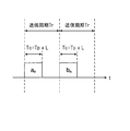
- FIG. 16 is an explanatory diagram of a transmission cycle Tr in a conventional pulse compression radar and complementary codes a n and b n which are transmission codes used in transmission in each transmission cycle.
- the received signal is expressed by Equation (4) due to the Doppler frequency f d generated along with the movement.
- the parameter t indicates time.
- a transmission interval for transmitting each high-frequency transmission signal generated based on the complementary codes a n and b n is defined as a transmission period Tr .
- the next transmission cycle T r receives a signal of the reflected wave with respect to the high frequency transmission signal generated based on the complementary code b n.
- this reflected wave signal is subjected to the phase change ⁇ (t) shown in Equation (4).
- a parameter T p is a transmission time per pulse corresponding to a pulse code having a code length L.
- Parameter T c is the transmission time in the transmission section of the complementary code a n or complementary code b n frequency transmission signal generated respectively based on the code length L.
- Patent document 1 is known in relation to the problem of deterioration.
- the dispersion compression type pulse echo system transmitting / receiving apparatus disclosed in Patent Document 1 transmits, in a time division manner, a high-frequency signal modulated with a code sequence having a different pulse compression code in accordance with each mode (B mode, Doppler mode). Specifically, the transmission / reception apparatus transmits a high-frequency signal modulated with a complementary code sequence for the short-range range in the B mode. Further, the transmission / reception apparatus transmits a high-frequency transmission signal modulated by a Barker code sequence or an M sequence in the Doppler mode. As a result, transmission pulses can be properly used according to the target to be measured, and pulse echoes caused by targets that move quickly at a short distance can be reduced.
- the reflected wave from the target located at a relatively far position is in the range side lobe of the reflected wave signal from the target located relatively near the radar apparatus.
- the main lobe of the signal was sometimes buried.
- the detection accuracy of the target existing at a distant position deteriorates, and thus the above-described problem greatly affects the measurement performance of the radar apparatus.
- pulse compression is performed by alternately switching between a complementary code sequence used in the B mode and an M sequence code or a Barker code sequence used in the Doppler mode.
- a complementary code sequence used in the B mode when the target moves, degradation of the side lobe level when transmitting using a complementary code is not considered, and side lobe levels such as an M-sequence code and a Barker code sequence are not considered.
- the peak side lobe level is approximately 20 Log (L) for a Barker code sequence having a code length L. Therefore, even in the case of the longest code length 13 known as the Barker code, since the peak sidelobe level is about 22.3 [dB], the measurement performance of the radar apparatus is affected.
- an object of the present invention is to provide a radar apparatus that suppresses degradation of separation performance in detection of a plurality of targets.
- the present invention is a radar apparatus as described above, wherein a code generation unit that generates a first code sequence and a second code sequence that form a pair of complementary codes, a first transmission sequence by modulating the first code sequence, The first modulation unit to be generated, the second modulation unit to modulate the second code sequence to generate the second transmission signal, and the first and second transmission signals respectively generated by the first and second modulation units are used.
- a quadrature modulation unit that performs quadrature modulation, an amplification unit that generates a high-frequency transmission signal from a signal that is quadrature-modulated by the quadrature modulation unit, and an antenna unit that transmits the high-frequency transmission signal from a transmission antenna.
- the detection of a plurality of targets is performed by maintaining the low range side lobe characteristics in the signal of the reflected wave from the target and effectively suppressing the range side lobe level. It is possible to suppress the degradation of the separation performance in.
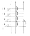
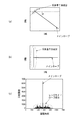
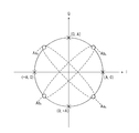
- the block diagram which shows the internal structure of the radar apparatus of 1st Embodiment. Timing chart for the operation of the radar apparatus of the first embodiment, (a) illustrates the transmission codes used in the transmission period T r and the transmission cycle T r, (b) illustrates the measurement zone, (c) each Explanatory drawing explaining the relationship between transmission cycle Tr and discrete time k Signal point arrangement diagram of high-frequency transmission signal IQ-multiplexed in the radar apparatus of the first embodiment An explanatory diagram showing the IQ correlation value AC (k) on the IQ plane, (a) an explanatory diagram of the IQ correlation value AC (k) before the subtraction processing by the subtraction unit, and (b) when used for the subtraction processing by the subtraction unit.
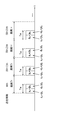
- Timing chart for the operation of the radar apparatus of the second embodiment (a) illustrates the transmission codes used in the transmission period T r and the transmission cycle T r, (b) illustrates the measurement zone, (c) each Explanatory drawing explaining the relationship between transmission cycle Tr and discrete time k Signal constellation diagram of IQ multiplexed radio frequency transmission signal in the radar apparatus of the second embodiment, at the M-th and the (M + 2) th transmission period, the complementary code a n on I axis (a), the complementary code b Signal constellation diagram of transmission signal IQ-multiplexed by assigning each b n to Q-axis, (b) Complementary code b n on I-axis at (M + 1) th and (M + 3) th transmission cycles constellation diagram of a transmission signal IQ multiplexing assigns each a n to Q axis Explanatory drawing which shows the detail of the transmission code used for each transmission cycle Tr in the radar apparatus of 2nd Embodiment.
- the block diagram which shows the internal structure of the radar transmission part in the modification 1 of each embodiment (a) The block diagram which shows the internal structure of the radar transmission part of the modification 1 of 1st Embodiment, (b) 2nd implementation The block diagram which shows the internal structure of the radar transmission part of the modification 1 of an aspect Complementary code a n is assigned -45 degree phase shift to the I-axis, the signal point arrangement diagram of a complementary code b n is -45 degree phase shift assigned to the Q axis IQ-multiplexed high-frequency transmission signal.
- the block diagram which shows the internal structure of the signal processing part of the radar receiving part in the modification 2 of each embodiment (a) The block diagram which shows the internal structure of the signal processing part of the radar receiving part of the modification 2 of 1st Embodiment (B) The block diagram which shows the internal structure of the signal processing part of the radar receiving part of the modification 2 of 2nd Embodiment.
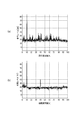
- An explanatory diagram showing a simulation result relating to target detection accuracy (a) an explanatory diagram when each high-frequency transmission signal generated based on complementary codes a n and b n in a conventional radar device is transmitted in a time-sharing manner; b) Explanatory drawing when a high-frequency transmission signal generated by IQ multiplexing of complementary codes a n and b n is transmitted by the radar apparatus of the first embodiment.
- the block diagram which shows the other internal structure of the transmission signal generation part in the radar apparatus of 2nd Embodiment.
- Explanatory drawing showing a procedure for generating a code sequence of a general complementary code Explanatory drawing explaining the nature of the conventional complementary code, (a) explanatory drawing showing the autocorrelation calculation result of one complementary code sequence, (b) explanatory drawing showing the autocorrelation calculation result of the other complementary code sequence, (c) ) Explanatory drawing showing the added value of autocorrelation calculation results of two complementary code sequences Explanatory diagram of transmission cycle and transmission code used in each transmission cycle in conventional pulse compression radar
- the reception signal received by the radar apparatus includes a reflected wave signal obtained by reflecting a high-frequency transmission signal transmitted from the radar apparatus by a target, and a noise signal around the radar apparatus. And are included.
- FIG. 1 is a block diagram showing an internal configuration of the radar apparatus 1 according to the first embodiment.
- FIG. 2 is a timing chart regarding the operation of the radar apparatus 1 according to the first embodiment.
- FIG (a) is an explanatory view of the transmission codes used in the transmission cycle T r and the transmission cycle T r.
- FIG. 4B is an explanatory diagram of the measurement section.
- FIG. 4C is an explanatory diagram for explaining the relationship between each transmission cycle Tr and the discrete time k.
- FIG. 3 is a signal point arrangement diagram of a high-frequency transmission signal that is IQ-multiplexed in the radar apparatus 1 according to the first embodiment.
- FIG. 4 is an explanatory diagram showing the IQ correlation value AC (k) on the IQ plane.
- FIG. 6A is an explanatory diagram of the IQ correlation value AC (k) before the subtraction processing by the subtraction unit 31.
- FIG. 6B is an explanatory diagram of the IQ correlation value AC (k) when used in the subtraction process by the subtraction unit 31.
- FIG. 6C is an explanatory diagram showing the relationship between the discrete time k and the absolute value
- the radar apparatus 1 includes a reference oscillator L 0 , a radar transmission unit 2 to which a transmission antenna ANT 0 is connected, and a radar reception unit 3 to which a reception antenna ANT 1 is connected.
- the radar apparatus 1 transmits a predetermined intermittent high-frequency transmission signal generated by the radar transmission unit 2 from the transmission antenna ANT 0, and receives a reflected wave signal reflected by the target by the radar reception unit 3.
- the radar apparatus 1 detects the presence / absence of a target by performing signal processing on the reception signal received by the radar receiver 3.
- the target is an object to be detected by the radar apparatus 1 and is, for example, an automobile or a person, and the same applies to the following embodiments.
- the radar transmission unit 2 includes a transmission signal generation unit 4 and a transmission RF (Radio Frequency) unit 11.
- the transmission signal generation unit 4 includes a first code generation unit 5, a second code generation unit 6, a first modulation unit 7, a second modulation unit 8, an LPF (Low Pass Filter) 9, and an LPF 10. .
- the transmission signal generation unit 4 is configured to include the LPF 9 and the LPF 10, but the LPF 9 and LPF 10 may be configured in the radar transmission unit 2 independently of the transmission signal generation unit 4.
- the transmission RF unit 11 includes a local oscillator L 1 , a mixer 12, a first phase shift unit 13, a mixer 14, an adder 15, and an amplifier 16.
- the transmission signal generation unit 4 Based on the reference signal generated by the reference oscillator L 0 , the transmission signal generation unit 4 generates a signal obtained by multiplying the reference signal by a predetermined factor. Each unit of the transmission signal generation unit 4 operates based on the generated signal.
- the transmission signal generation unit 4 periodically generates a baseband transmission signal by modulating the pulse compression codes of the complementary code sequences a n and b n having the code length L, respectively.
- n 1,..., L
- the parameter L represents the code length of the complementary code sequences a n and b n .
- the transmission signal generated by the transmission signal generation unit 4 is not a continuous signal.
- the complementary code sequences a n and b n of the code length L thus, there are N 0 [number] samples per pulse code.
- the parameter M is a natural number.
- N u [number] samples as baseband transmission signals.
- the first code generating unit 5 generates a transmission code for pulse compression of the complementary code sequence a n is a pair of complementary code sequence with a code length L.
- the transmission code of the complementary code sequences a n are described as conveniently transmitted symbols a n.
- the second code generation unit 6 generates a transmission code for pulse compression of a complementary code sequence b n that is a pair of complementary code sequences of code length L.
- the second code generation unit 6 outputs the generated transmission code of the complementary code sequence b n to the second modulation unit 8.
- the transmission code of the complementary code sequence b n is referred to as a transmission code b n for convenience.
- First modulation unit 7 inputs the transmission code a n output by the first code generating unit 5.
- First modulation unit 7 performs pulse modulation to the transmission code a n which is the input (amplitude modulation, ASK (Amplitude Shift Keying)) or phase modulation (PSK (Phase Shift Keying)) , baseband transmission signal I (k) is generated.
- the first modulation unit 7 outputs, to the transmission RF unit 11, a transmission signal I (k) that is equal to or less than a preset limit band among the generated transmission signal I (k) via the LPF 9.
- the second modulation unit 8 receives the transmission code b n output from the second code generation unit 6.
- the second modulation unit 8 performs pulse modulation (amplitude modulation, ASK) or phase modulation (PSK) on the input transmission code b n to generate a baseband transmission signal Q (k).
- the second modulation unit 8 outputs, to the transmission RF unit 11, the transmission signal Q (k) that is equal to or less than a preset limit band among the generated transmission signal Q (k) via the LPF 10.
- Transmission RF unit 11 based on the reference signal generated by reference oscillator L 0, to generate a signal multiplied the reference signal to a predetermined multiple.
- the transmission RF unit 11 operates based on the generated signal.
- the transmission RF unit 11 assigns the transmission signal I (k) output from the first modulation unit 7 to the I axis on the IQ plane shown in FIG. Further, the transmission RF unit 11 assigns the transmission signal Q (k) output from the second modulation unit 8 to the Q axis on the IQ plane shown in FIG.
- the transmission RF unit 11 additively multiplexes the transmission signal I (k) assigned to the I axis and the transmission signal Q (k) assigned to the Q axis.
- the transmission signal I (k) output from the first modulation unit 7 is assigned to the I axis
- the transmission signal Q (k) output from the second modulation unit 8 is assigned to the Q axis. Processing for generating a high-frequency transmission signal by additively multiplexing the signals I (k) and Q (k) is referred to as “IQ multiplexing”.
- the details of the IQ multiplexing process will be described in detail.
- the IQ multiplexing is performed by the mixer 12, the first phase shift unit 13, the mixer 14, and the addition unit 15 in the transmission RF unit 11.
- the mixer 12, the first phase shift unit 13, the mixer 14, and the addition unit 15 may be described as an orthogonal modulation unit that performs IQ multiplexing.
- Transmission signal I output by the first modulation section 7 (k), at the mixer 12 is multiplied with the signal from the local oscillator L 1 carrier frequency f c Acos (2 ⁇ f c t) .
- the parameter A indicates a predetermined amplitude value.
- Signals multiplied by the mixers 12 and 14 are added by the adder 15.
- the orthogonally modulated high-frequency transmission signal s (t) shown in Equation (6) is generated by IQ multiplexing of the transmission codes a n and b n .
- Constellation diagram shown in FIG. 3 the transmission code a n of the complementary code in I axis, the transmission code b n of complementary codes allocated to the Q axis, is a signal point arrangement diagram of the IQ-multiplexed high-frequency transmission signal . Therefore, the high-frequency transmission signal s (t) shown in the equation (6) has signal points (A, A), (A, -A), (-A, A) and (-A, -A) shown in FIG. of, as one is selected, in which the transmission code a n and transmission code b n have been generated are IQ multiplexed.
- Amplifier 16 enter the formula (6) RF-value transmission signal s (t) generated according amplifies the level of the input high frequency-value transmission signal s (t) to a predetermined level, the transmission antenna ANT 0 Output.
- the amplified radio frequency transmission signal s (t) is transmitted so as to radiate into the space through the transmission antenna ANT 0.
- the transmission antenna ANT 0 transmits the high-frequency transmission signal s (t) output by the transmission RF unit 11 so as to be radiated into space. As shown in FIG. 2 (a), the high frequency transmission signal s (t) it is transmitted between the transmission interval T w of the transmission cycle T r, transmission between the non-transmission period (T r -T w) Not.
- the radar receiving unit 3 includes a receiving antenna ANT 1 , a receiving RF unit 17, and a signal processing unit 21.
- the reception RF unit 17 includes an amplifier 18, a frequency conversion unit 19, and a quadrature detection unit 20.
- the signal processing unit 21 includes: A / D conversion units 22 and 23; first and second reference signal generation units 24 and 25; first and second correlation value calculation units 26 and 27; an addition unit 28; A signal extraction unit 29, an IQ multiple interference component extraction unit 30, a subtraction unit 31, an averaging processing unit 32, and an arrival distance estimation unit 33 are provided.
- the radar receiving unit 3 periodically calculates each transmission cycle Tr as a signal processing section in the signal processing unit 21.
- the reception antenna ANT 1 receives a reflected wave signal obtained by reflecting the high-frequency transmission signal s (t) transmitted from the radar transmission unit 2 by the target and a noise signal around the radar apparatus 1 as a reception signal.
- the reflected wave signal is a high frequency band signal.
- a reception signal received by the reception antenna ANT 1 is input to the reception RF unit 17.
- the radar receiver 3 holds one receiving antenna ANT 1 .
- the reception antenna ANT 1 receives the reception signal described above in a section corresponding to each transmission cycle Tr . Accordingly, a section Tr in which the received signal is received is set as a measurement section in the radar apparatus 1.
- Reception RF section 17 like the transmission RF unit 11, based on the reference signal generated by reference oscillator L 0, to generate a signal multiplied the reference signal to a predetermined times.
- the reception RF unit 17 operates based on the generated signal. This makes it possible to take the synchronization between the local oscillator L 1 of the transmission RF unit 11 and the local oscillator of the receiver RF unit 17 (not shown).
- the amplifier 18 receives the reception signal in the high frequency band received by the reception antenna ANT 1 , amplifies the level of the input reception signal in the high frequency band, and outputs the amplified signal to the frequency conversion unit 19.
- the frequency converter 19 receives the received signal in the high frequency band output from the amplifier 18, down-converts the input received signal in the high frequency band to the baseband, and converts the received signal thus down-converted into a quadrature detector 20 is output.
- the quadrature detection unit 20 generates a baseband reception signal composed of an in-phase signal (in-phase signal) and a quadrature signal (quadrate signal) by performing quadrature detection on the baseband reception signal output from the frequency conversion unit 19. To do.
- the quadrature detection unit 20 outputs the in-phase signal component of the generated reception signal to the A / D conversion unit 22, and outputs the quadrature signal component of the generated reception signal to the A / D conversion unit 23. .
- the A / D conversion unit 22 samples the baseband in-phase signal output from the quadrature detection unit 20 at a discrete time k and converts the in-phase signal of analog data into digital data.
- the A / D converter 22 outputs the in-phase signal of the converted digital data to the first correlation value calculator 26.
- the A / D conversion unit 23 performs sampling at the discrete time k on the baseband quadrature signal output from the quadrature detection unit 20, and converts the quadrature signal of analog data into digital data.
- the A / D conversion unit 23 outputs the orthogonal signal of the converted digital data to the second correlation value calculation unit 27.
- the parameter k corresponds to the number of samples of the baseband transmission signals I (k) and Q (k) that are the basis of the high-frequency transmission signal transmitted in each transmission period Tr shown in FIG. Represents a discrete time.
- the received signal at the discrete time k converted by the A / D converters 22 and 23 is expressed by a mathematical formula ( 7) as a complex signal.
- the range of the discrete time k is the same in each embodiment described later.
- the discrete time k (N r + N u ) shows a time point immediately before end of transmission code a n and transmission code b n are transmission cycle T r of the high frequency transmission signal s generated are IQ-multiplexed (t).
- T r transmission cycle
- the range of the discrete time k is shown only in the Mth transmission cycle.
- the first reference signal generation unit 24 synchronizes with the operation of the transmission signal generation unit 4 and multiplies the reference signal by a predetermined multiple on the basis of the reference signal generated by the reference oscillator L 0 in the same manner as the transmission signal generation unit 4. A signal multiplied by is generated.
- the first reference signal generation unit 24 generates a first reference transmission signal I (k) having the same baseband as the transmission signal I (k) generated by the first modulation unit 7 based on the generated signal. To do.
- the first reference signal generation unit 24 outputs the generated first reference transmission signal I (k) to the first correlation value calculation unit 26. In FIG. 1, description of input of the reference signal to the first reference signal generation unit 24 is omitted.
- the second reference signal generation unit 25 synchronizes with the operation of the transmission signal generation unit 4 and multiplies the reference signal by a predetermined multiple based on the reference signal generated by the reference oscillator L 0 in the same manner as the transmission signal generation unit 4. A signal multiplied by is generated. Based on the generated signal, the second reference signal generation unit 25 applies the same baseband transmission signal Q (k) as the transmission signal Q (k) generated by the second modulation unit 8 to IQ multiplexing. A second reference transmission signal jQ (k) with a Q-axis phase rotation is periodically generated. The second reference signal generation unit 25 outputs the generated second reference transmission signal jQ (k) to the second correlation value calculation unit 27. In FIG. 1, description of input of the reference signal to the second reference signal generation unit 25 is omitted.
- the first correlation value calculator 26 is a digital data complex signal x (k) output from the A / D converter 22 and a first reference transmission signal I (k) output from the first reference signal generator 24. ). The first correlation value calculator 26 calculates a first correlation value AC 1 (k) between the input complex signal x (k) and the first reference transmission signal I (k). Note that * (asterisk) represents a complex conjugate operator.
- the first correlation value calculation unit 26 outputs the first correlation value AC 1 (k) calculated according to Equation (8) to the addition unit 28.
- the second correlation value calculation unit 27 includes the complex signal x (k) of the digital data output from the A / D conversion unit 23 and the second reference transmission signal jQ (k) output from the second reference signal generation unit 25. ).
- the second correlation value calculator 27 calculates a second correlation value AC 2 (k) between the input complex signal x (k) and the second reference transmission signal jQ (k). Note that * (asterisk) represents a complex conjugate operator.
- the second correlation value calculation unit 27 outputs the second correlation value AC 2 (k) calculated according to Equation (9) to the addition unit 28.
- the measurement range (k range) may be further limited by the presence range of the target to be measured by the radar apparatus.
- the radar apparatus 1 can reduce the calculation amounts of the first correlation value calculation unit 26 and the second correlation value calculation unit 27, respectively. That is, the radar apparatus 1 can reduce the power consumption based on the reduction in the amount of calculation by the signal processing unit 21.
- the adder 28 receives the first correlation value AC 1 (k) output from the first correlation value calculator 26 and the second correlation value AC 2 (k) output from the second correlation value calculator 27. To do. The adder 28 adds the input first correlation value AC 1 (k) and the second correlation value AC 2 (k) as shown in Expression (10) in a state where the discrete times k are aligned. The third correlation value AC (k) is then calculated. In the following description, the third correlation value added by the adding unit 28 is referred to as “IQ correlation value”. The adder 28 outputs the calculated IQ correlation value AC (k) to the received signal extractor 29 and the subtractor 31, respectively.
- the first correlation value calculation unit 26 and the second correlation value calculation unit 27 can be applied with reference to, for example, the complementary code fast correlator described in Reference Non-Patent Document 1 below. The same applies to the following embodiments.
- the reception signal extraction unit 29 receives the IQ correlation value AC (k) output from the addition unit 28.
- the reception signal extraction unit 29 extracts an IQ correlation value AC (k pq ) exceeding a predetermined threshold B set in advance from the input IQ correlation value AC (k).
- the reception signal extraction unit 29 extracts the discrete time k pq that satisfies Equation (11), and the IQ correlation values AC (k pq ) corresponding to the extracted discrete time k pq are arranged in descending order.
- AC (k p1 ), AC (k p2 ),..., AC (k pv ) are output to IQ multiple interference component extraction unit 30.
- the parameters p1, p2,..., Pv are each a natural number of samples 1 to (N r + N u ) and correspond to an IQ correlation value AC (k pq ) that satisfies the formula (11).
- the predetermined threshold B is a level obtained by adding a predetermined margin (about 3 [dB] to 10 [dB]) to the noise level. The same applies to the predetermined threshold B in the following embodiments.
- the IQ multiple interference component extraction unit 30 receives the IQ correlation values AC (k pq ) output from the reception signal extraction unit 29.
- Im ⁇ x ⁇ is an operator that extracts the imaginary component of the complex number x.
- the IQ multiple interference component extraction unit 30 outputs the calculated IQ multiple interference component to the subtraction unit 31.
- the subtracting unit 31 inputs the IQ multiple interference component output by the IQ multiple interference component extracting unit 30. Further, as shown in the equation (13), the subtraction unit 31 calculates the IQ multiple interference component calculated based on the equation (12) from the IQ correlation value AC (k pq ) extracted by the reception signal extraction unit 29. A fourth correlation value AC ′ (k pq ) from which IQ multiple interference components have been removed is derived by removing (subtracting).
- k k pq ⁇ N 0 L + 1, k pq ,..., K pq + N 0 L ⁇ 1.
- k ⁇ 1 or k> (N r + N u ) it is not included in the range for performing the subtraction process.
- FIGS. 4A and 4B are explanatory diagrams in which IQ correlation values AC (k) are plotted on a complex plane composed of the I axis and the Q axis.
- FIG. 4C is a graph in which the absolute value
- transmission cycle T r which is the complementary code transmission code a n and transmission code b n are generated are IQ-multiplexed high-frequency-value transmission signal s (t) is transmitted in the radar transmitter 2
- the transmission code a n and the transmission code b n are not orthogonal codes but codes having cross-correlation. Accordingly, such transmission code a n and transmission code b n is when the high frequency transmission signal s generated are IQ-multiplexed (t) is transmitted is reflected by the target of the high frequency transmission signal s (t) An IQ multiple interference component is generated in the reflected wave signal.
- the IQ correlation value AC (k) obtained by the adder 28 of the radar receiver 3 is shown in FIG.
- An IQ multiple interference component appears as a peak range side lobe in a direction orthogonal to the peak direction ⁇ (k pq ) of the IQ correlation value AC (k pq ) that satisfies the above formula (11).
- this IQ multiple interference component corresponds to the range side lobe component shown in the portion surrounded by the dotted line.
- the IQ multiple interference component extraction unit 30 calculates a component (see Expression (12)) orthogonal to the peak direction ⁇ (k pq ) of the IQ correlation value AC (k pq ), whereby the dotted line in FIG. It is possible to extract the range side lobe component in the IQ correlation value AC (k pq ) shown in the portion surrounded by.
- Equation (12) Since the phase rotation ⁇ (k pq ) is given to extract the IQ multiple interference component as shown in Equation (12), the second value on the right side of Equation (13) is used to obtain the original phase component.
- the coefficient exp (j ⁇ (k pq )) is multiplied.
- Im ⁇ x ⁇ in the second expression on the right side of Equation (13) is an operator that extracts the imaginary number component of the complex number x, but the subtraction unit 31 returns to the original imaginary number component.
- a complex coefficient j indicating the application of 90 degree phase rotation is multiplied.
- the subtraction unit 31 can remove the range side lobe component from each IQ correlation value AC (k) extracted by the reception signal extraction unit 29 according to the equation (13).
- the averaging processing unit 32 inputs the fourth correlation value AC ′ (k) derived by the subtracting unit 31.
- the averaging processing unit 32 averages each fourth correlation value AC ′ (k) input over a predetermined plurality of transmission periods Tr .
- the averaging processing unit 32 outputs the average value of the averaged fourth correlation values AC ′ (k) to the arrival distance estimating unit 33. Thereby, the radar apparatus 1 can suppress noise components around the radar apparatus 1 and improve the measurement performance related to the estimation of the arrival angle and distance of the target.
- the arrival distance estimation unit 33 inputs the average value output by the averaging processing unit 32.
- the arrival distance estimation unit 33 performs an estimation calculation of the distance to the target based on the input average value.
- the calculation for estimating the distance to the target by the arrival distance estimation unit 33 is a known technique, and can be realized by referring to the following non-patent document 2, for example.
- the arrival distance estimation unit 33 based on the fourth correlation value of the average value calculated by the averaging processing unit 32, the discrete time and the transmission time of the high-frequency transmission signal when the fourth correlation value takes the maximum value. And determine the time difference. Furthermore, the arrival distance estimation unit 33 estimates the distance to the target based on the determined time difference.
- the radar apparatus 1 of the first embodiment even when the target moves, the low range side lobe characteristic in the signal of the reflected wave from the target is maintained, and the range side lobe level is effectively suppressed. As a result, it is possible to suppress the degradation of the separation performance in the detection of a plurality of targets.
- Patent Document 1 in order to obtain a single pulse compression result, three types of code sequences, that is, two types of codes that form a pair of complementary code sequences and one type of Barker code or M sequence code, etc. Therefore, it was necessary to take a time corresponding to a total of three transmission cycles.
- the radar apparatus 1 of the first embodiment in order to IQ multiplexing the transmission code a n and transmission code b n during transmission, in order to obtain a single measurement result, corresponding to the transmission period of a total of one It takes time to do. For this reason, according to the radar apparatus 1, the number of times of measurement within a predetermined time can be increased, that is, the measurement performance can be improved.
- FIG. 5 is a block diagram showing an internal configuration of the radar apparatus 1a according to the second embodiment.
- FIG. 6 is a timing chart regarding the operation of the radar apparatus 1a according to the second embodiment.
- FIG (a) is an explanatory view of the transmission codes used in the transmission cycle T r and the transmission cycle T r.
- FIG. 4B is an explanatory diagram of the measurement section.
- FIG. 4C is an explanatory diagram for explaining the relationship between each transmission cycle Tr and the discrete time k.
- FIG. 7 is a signal point arrangement diagram of transmission signals in the radar apparatus 1a of the second embodiment.
- FIG (a) is a M-th and the (M + 2) th transmission period, the complementary code a n on I axis, the signal point arrangement of the transmission signal the complementary code b n and IQ multiplexed allocated to the Q axis
- FIG. (b) is a (M + 1) th -th and the (M + 3) th transmission period, the complementary code b n to the I axis, the signal of the transmission signal the complementary code a n and IQ multiplexed allocated to the Q axis
- FIG. 8 is an explanatory diagram showing details of transmission codes used in each transmission cycle Tr in the radar apparatus 1a of the second embodiment.
- the radar device 1a for each transmission cycle T r, switches the transmission code to be assigned to the I axis of the transmission code that IQ multiplexing to alternate between transmission code a n a transmission code b n, alternately switching the transmission code to be assigned to the Q axis between a transmission code b n a transmission code a n. Furthermore, in the second embodiment, the Doppler frequency f d generated with the movement of the target is calculated, and IQ multiple interference components are removed for the IQ correlation value exceeding the calculated Doppler frequency f d .
- the radar apparatus 1 a includes a reference oscillator L 0 , a radar transmitter 2 a to which the transmission antenna ANT 0 is connected, and a radar receiver 3 a to which the reception antenna ANT 1 is connected.
- the radar apparatus 1a transmits a predetermined intermittent high frequency transmission signal generated by the radar transmitter 2a from the transmission antenna ANT 0, it receives a signal of the reflected wave reflected on the target by the radar receiver 3a.
- the radar apparatus 1 detects the presence / absence of a target by performing signal processing on the reception signal received by the radar receiver 3a.
- the radar transmitter 2a includes a transmission signal generator 4a and a transmission RF unit 11.
- the transmission signal generation unit 4a includes a first code generation unit 5a, a second code generation unit 6a, a first switch unit SW1, a second switch unit SW2, a transmission code control unit CT1, and a first modulation unit 7a.
- the second modulation unit 8a, the LPF 9, and the LPF 10 are provided.
- the transmission signal generation unit 4a is configured to include the LPF 9 and the LPF 10, but the LPF 9 and LPF 10 may be configured in the radar transmission unit 2a independently of the transmission signal generation unit 4a. Since the configuration and operation of the transmission RF unit 11 are the same as those in the first embodiment, description of the configuration and operation is omitted.
- Transmission signal generating unit 4a based on the reference signal generated by reference oscillator L 0, to generate a timing clock obtained by multiplying the reference signal to a predetermined times. Each unit of the transmission signal generation unit 4a operates based on the generated timing clock.
- the transmission signal generation unit 4a periodically generates a baseband transmission signal by modulating the pulse compression codes of the complementary code sequences a n and b n each having a code length L.
- n 1,..., L
- the parameter L represents the code length of the complementary code sequences a n and b n .
- the transmission signal generated by the transmission signal generation unit 4a is not a continuous signal.
- the transmission interval T w of the M-th, second (M + 3) -th each transmission cycle T r, the complementary code sequence a n of the code length L, with respect to b n There are N 0 samples per pulse code.
- N 0 samples exist as baseband transmission signals in the non-transmission period (T r ⁇ T w ) of each of the Mth to (M + 3) th transmission periods T r .
- the first code generating unit 5a generates a transmission code for pulse compression of the complementary code sequence a n is a pair of complementary code sequence with a code length L.
- the first code generating unit 5a and outputs the transmission code a n which is the product to the first switch unit SW1 and the second switch SW2.
- the second code generating unit 6a generates a transmission code for pulse compression of the complementary code sequence b n is a pair of complementary code sequence with a code length L.
- the second code generation unit 6a outputs the generated transmission code b n to the first switch unit SW1 and the second switch unit SW2, respectively.
- the first switch unit SW1 inputs the transmission code a n and transmission code b n respectively output by the first code generating unit 5a and the second code production section 6a.
- the first switch unit SW1 is based on the outputted code switching control signal by the transmission code controller CT1, selectively one of the transmission code of the transmission code a n and transmission code b n which is the input
- the switched transmission code is output to the first modulation unit 7a.
- Second switch SW2 inputs the transmission code a n and transmission code b n respectively output by the first code generating unit 5a and the second code production section 6a.
- the second switch unit SW2 based on the outputted code switching control signal by the transmission code controller CT1, selectively one of the transmission code of the transmission code a n and transmission code b n which is the input
- the switched transmission code is output to the second modulation unit 8a.
- Transmission code controller CT1 for each transmission cycle T r, the first switch unit so as to switch the transmission code a n and the transmission code b n are input to the first switch unit SW1 and the second switch SW2 selectively SW1 and the second switch unit SW2 are controlled. That is, the transmission code control unit CT1 outputs a code switching control signal for selectively switching the transmission code to the first switch unit SW1 and the second switch unit SW2 for each transmission cycle Tr .
- Transmission code controller CT1 is, in the M-th transmission cycle T r, controls the first switch unit SW1 so as to output the transmission code a n to the first modulation section 7a. That is, the transmission code controller CT1 outputs the M-th transmission cycle T r, the sign switching control signal indicating to switch to transmission code a n to the first switch unit SW1. Further, the transmission code control unit CT1 controls the second switch unit SW2 so that the transmission code b n is output to the second modulation unit 8a in the M-th transmission cycle Tr . That is, the transmission code control unit CT1 outputs a code switching control signal for switching to the transmission code b n to the second switch unit SW2 in the M-th transmission cycle Tr .
- the transmission code controller CT1 may control the first (M + 1) th transmit the cycle T r, the first switch unit SW1 so as to output the transmission code b n to the first modulation section 7a. That is, the transmission code control unit CT1 outputs a code switching control signal for switching to the transmission code b n to the first switch unit SW1 in the (M + 1) -th transmission cycle Tr .
- the transmission code controller CT1 may control the first (M + 1) th transmit the cycle T r, the second switch unit SW2 so as to output the transmission code a n to a second modulation section 8a. That is, the transmission code controller CT1 outputs the first (M + 1) th transmission cycle T r, the sign switching control signal indicating to switch to transmission code a n to the second switch SW2.
- the transmission code controller CT1 may control the first (M + 2) th transmit the cycle T r, the first switch unit SW1 so as to output the transmission code a n to the first modulation section 7a. That is, the transmission code controller CT1 outputs the first (M + 2) th transmission cycle T r, the sign switching control signal indicating to switch to transmission code a n to the first switch unit SW1.
- the transmission code controller CT1 may control the first (M + 2) th transmit the cycle T r, the second switch unit SW2 so as to output the transmission code b n to the second modulation unit 8a. That is, the transmission code controller CT1 outputs the first (M + 2) th transmission cycle T r, the sign switching control signal indicating switching to the transmission code b n to the second switch SW2.
- the transmission code control unit CT1 controls the first switch unit SW1 so as to output the transmission code b n to the first modulation unit 7a in the (M + 3) th transmission cycle Tr . That is, the transmission code controller CT1 outputs the first (M + 3) th transmission cycle T r, the sign switching control signal indicating switching to the transmission code b n to the first switch unit SW1.
- the transmission code controller CT1 may control the first (M + 3) -th in the transmission cycle T r, the second switch unit SW2 so as to output the transmission code a n to a second modulation section 8a. That is, the transmission code controller CT1 outputs the first (M + 3) th transmission cycle T r, the sign switching control signal indicating to switch to transmission code a n to the second switch SW2.
- the Mth and (M + 1) th total transmission cycles shown in FIG. 6A are taken as one unit, and each transmission cycle for each unit.
- a transmission code corresponding to is generated and repeatedly output to the first modulation unit 7a and the second modulation unit 8a.
- First modulation unit 7a inputs the transmission code a n or the transmission code b n outputted by the first switch unit SW1.
- First modulation unit 7a a pulse modulation to the transmission code a n or the transmission code b n is the input (amplitude modulation, ASK) performs or phase modulation (PSK), transmission signal I baseband (k) Generate.
- the first modulation unit 7 a outputs, to the transmission RF unit 11, a transmission signal I (k) that is equal to or less than a preset limit band among the generated transmission signal I (k) via the LPF 9.
- Second modulation section 8a inputs the transmission code b n or transmission code a n outputted by the second switch SW2.
- the second modulation unit 8a, the pulse modulation on the transmission code b n or transmission code a n is the input (amplitude modulation, ASK) performs or phase modulation (PSK), transmission signal Q baseband (k) Generate.
- the second modulation unit 8 a outputs, to the transmission RF unit 11, a transmission signal Q (k) that is equal to or less than a preset limit band among the generated transmission signal Q (k) via the LPF 10.
- the signal point arrangement diagram of the high-frequency transmission signal IQ-multiplexed by the transmission RF unit 11 is input to the first modulation unit 7a and the second modulation unit 8a by the transmission code control unit CT1, respectively. Different transmission codes. For this reason, the signal point arrangement diagram of the high-frequency transmission signal IQ-multiplexed by the transmission RF unit 11 is different for each transmission cycle Tr as shown in FIGS. 7 (a) and 7 (b).
- I-axis transmission code a n 7 is a signal point arrangement diagram of high-frequency transmission signals IQ-multiplexed by assigning transmission codes b n to the Q-axis. Therefore, the high-frequency transmission signal s (t) shown in the above equation (6) has the signal points (A, A), (A, ⁇ A), ( ⁇ A, A) and ( ⁇ ) shown in FIG.
- the transmission codes a n and b n are generated by IQ multiplexing so that one of A, -A) is selected.
- the transmission code b n is set to the I axis in the (M + 1) -th and (M + 3) -th transmission cycles Tr shown in FIG. 6A.
- a signal point arrangement diagram of the IQ-multiplexed high-frequency transmission signal by assigning each a transmission code a n to Q axis. Therefore, the high-frequency transmission signal s (t) shown in the above equation (6) has signal points (A, A), (A, -A), (-A, A) and (- The transmission codes a n and b n are generated by IQ multiplexing so that one of A, -A) is selected.
- the radar receiving unit 3a includes a receiving antenna ANT 1 , a receiving RF unit 17, and a signal processing unit 21a.
- the reception RF unit 17 includes an amplifier 18, a frequency conversion unit 19, and a quadrature detection unit 20.
- the signal processing unit 21a includes A / D conversion units 22 and 23, first and second reference signal generation units 24a and 25a, first and second correlation value calculation units 26a and 27a, an addition unit 28a, and reception.
- a signal selection unit 29a, an IQ multiple interference component extraction unit 30, a subtraction unit 31, an averaging processing unit 32, an arrival distance estimation unit 33, and a Doppler frequency estimation unit 34 are provided.
- the radar receiver 3a periodically calculates a double transmission cycle T r (2T r ) as a signal processing section in the signal processor 21a.
- the reception antenna ANT 1 receives the reception signal described above in a section corresponding to each transmission cycle Tr . Accordingly, the section Tr in which the received signal is received is set as a measurement section in the radar apparatus 1a.
- the transmission code a n and the transmission code b n are alternately switched every transmission cycle T r and subjected to IQ multiplexing, and as a result, the generated high-frequency transmission signal s (t ) Shows the time immediately before the end of the transmission cycle Tr .
- the range of the discrete time k is shown only in the Mth transmission cycle.
- First reference signal generating unit 24a is synchronized with the operation of the transmission signal generator 4a, based on the reference signal generated by reference oscillator L 0 as with the transmission signal generating unit 4a, predetermined times the reference signal A timing clock multiplied by is generated. Based on the generated timing clock, the first reference signal generation unit 24a receives the first reference transmission signal I (k) having the same baseband as the transmission signal I (k) generated by the first modulation unit 7a. Generate periodically.
- the transmission code control unit CT1 transmits the transmission code a generated by the first code generation unit 5a. n is output to the first modulation unit 7a via the first switch unit SW1. Also, in the (M + 1) th and (M + 3) th transmission cycles Tr shown in FIG. 6A, the transmission code control unit CT1 uses the transmission code b n generated by the second code generation unit 6a. And output to the first modulation unit 7a via the first switch unit SW1.
- the first reference signal generating unit 24a the M-th and the (M + 2) th each transmission cycle T r shown in FIG. 6 (a), the transmission code a n input to the first modulation section 7a
- a first reference transmission signal I (k) that is the same as the transmission signal I (k) generated based on this is generated.
- the first reference signal generation unit 24a transmits the transmission code b input to the first modulation unit 7a in each of the (M + 1) th and (M + 3) th transmission periods Tr shown in FIG.
- a first reference transmission signal I (k) identical to the transmission signal I (k) generated based on n is generated.
- the first reference signal generation unit 24a outputs the first reference transmission signal I (k) generated in each transmission cycle Tr to the first correlation value calculation unit 26a.
- the second reference signal generating unit 25a in synchronism with the operation of the transmission signal generator 4a, based on the reference signal generated by reference oscillator L 0 as with the transmission signal generating unit 4a, predetermined times the reference signal A timing clock multiplied by is generated. Based on the generated timing clock, the second reference signal generation unit 25a performs IQ multiplexing on the transmission signal Q (k) having the same baseband as the transmission signal Q (k) generated by the second modulation unit 8a.
- the second reference transmission signal jQ (k) to which the phase rotation of the Q axis is added is periodically generated.
- transmission code control unit CT1 transmits the transmission code b generated by the second code generation unit 6a. n is output to the second modulation unit 8a via the second switch unit SW2. Further, in the (M + 1) th position and the (M + 3) th transmission cycle T r shown in FIG. 6 (a), transmission code controller CT1 is a transmission code a n generated by the first code generating unit 5a And output to the second modulation section 8a via the first switch section SW1.
- the second reference signal generation unit 25a sets the transmission code b n input to the second modulation unit 8a in each of the Mth and (M + 2) th transmission periods Tr shown in FIG.
- a second reference transmission signal jQ (k) is generated by adding a Q-axis phase rotation in IQ multiplexing to the same transmission signal Q (k) as the transmission signal Q (k) generated based on the above. Further, the second reference signal generation unit 25a transmits the transmission code a input to the second modulation unit 8a in each of the (M + 1) th and (M + 3) th transmission periods Tr shown in FIG. 6A.
- a second reference transmission signal jQ (k) is generated by adding a Q-axis phase rotation in IQ multiplexing to the same transmission signal Q (k) as the transmission signal Q (k) generated based on n .
- the second reference signal generation unit 25a outputs the second reference transmission signal jQ (k) generated in each transmission cycle Tr to the second correlation value calculation unit 27a.
- the first correlation value calculator 26a includes the complex signal x (k) of the digital data output from the A / D converter 22 and the first reference transmission signal I (k) output from the first reference signal generator 24a. ). The first correlation value calculator 26a calculates a first correlation value AC 1 (k) between the input complex signal x (k) and the first reference transmission signal I (k). Note that * (asterisk) represents a complex conjugate operator.
- the first correlation value calculation unit 26a outputs the first correlation value AC 1 (k) calculated according to Equation (8) to the addition unit 28a.
- the second correlation value calculation unit 27a includes the digital signal complex signal x (k) output from the A / D conversion unit 23 and the second reference transmission signal jQ (k) output from the second reference signal generation unit 25a. ).
- the second correlation value calculator 27a calculates a second correlation value AC 2 (k) between the input complex signal x (k) and the second reference transmission signal jQ (k). Note that * (asterisk) represents a complex conjugate operator.
- the second correlation value calculation unit 27a outputs the second correlation value AC 2 (k) calculated according to Equation (9) to the addition unit 28a.
- the measurement range (k range) may be further limited by the presence range of the target to be measured by the radar apparatus.
- the radar apparatus 1a can reduce the amount of calculation of each of the first correlation value calculation unit 26a and the second correlation value calculation unit 27a. That is, the radar apparatus 1a can reduce the amount of power consumption based on the calculation amount by the signal processing unit 21a.
- the adder 28a receives the first correlation value AC 1 (k) output from the first correlation value calculator 26a and the second correlation value AC 2 (k) output from the second correlation value calculator 27a. To do.
- the adding unit 28a sets the input first correlation value AC 1 (k) and second correlation value AC 2 (k) to the above-described formula (10) in a state where the discrete times k are aligned.
- the adder 28a outputs the calculated IQ correlation value AC (k) to the received signal selector 29a and the subtractor 31, respectively.
- the adder 28 a outputs the first half correlation value AC sub1 (k) in the first half of the transmission interval T w of each transmission cycle T r out of the IQ correlation value AC (k) to the Doppler frequency estimation unit 34. Further, the addition section 28a, the correlation value late in the latter half portion of the transmission interval T w of each transmission cycle T r of the IQ correlation value AC (k) AC sub2 (k + (N r / 2)) Doppler frequency estimation unit 34 Output to.
- the Doppler frequency estimator 34 receives the first half correlation value AC sub1 (k) and the second half correlation value AC sub2 (k + (N r / 2)) respectively output from the adder 28a.
- the Doppler frequency estimation unit 34 performs the Doppler frequency f d in the IQ correlation value AC (k) based on the input first half correlation value AC sub1 (k) and second half correlation value AC sub2 (k + (N r / 2)). Is calculated.
- FIG. 8 is an explanatory diagram showing details of transmission codes used in each transmission cycle Tr in the radar apparatus 1a of the second embodiment.
- the complementary code sequences a n and b n are obtained by concatenating c n and d n which are pairs of sub-complementary codes having a code length L / 2 as shown in Equation (14). It is what was done. Note that c n and d n which are pairs of sub-complementary codes can be expressed as in Equation (15).
- the Doppler frequency estimator 34 adds the latter half correlation value AC sub2 (k + (N r / 2)) to give a 90 degree phase rotation to the latter half correlation value AC sub2 (k + (N r / 2)). Is multiplied by an imaginary coefficient j.
- the Doppler frequency estimator 34 provides the latter half correlation value AC sub2 (k + (N r / 2) in order to give a ⁇ 90 degree phase rotation to the latter half correlation value AC sub2 (k + (N r / 2)). ) Is multiplied by a complex coefficient -j.
- the reception signal selection unit 29a receives the IQ correlation value AC (k) output from the addition unit 28a and the Doppler frequency f d (k) output from the Doppler frequency estimation unit 34.
- the received signal selection unit 29a exceeds a predetermined threshold value B that is set in advance among the input IQ correlation value AC (k) and the input Doppler frequency f d (k) is set to a predetermined value.
- An IQ correlation value AC (k pq ) greater than or equal to the threshold D is selected.
- the reception signal selection unit 29a extracts the discrete time k pq that satisfies Equation (22), and the IQ correlation values AC (k pq ) corresponding to the extracted discrete time k pq are arranged in descending order.
- (K p1 ), AC (k p2 ),..., AC (k pv ) are respectively output to the IQ multiple interference component extraction unit 30.
- the parameters p1, p2,..., Pv are each a natural number of samples 1 to (N r + N u ) and correspond to an IQ correlation value AC (k pq ) that satisfies the formula (11).
- the predetermined threshold value D shows the signal processing portion 21a, when signal processing, the value that can not be ignored the influence of the Doppler frequency f d which is generated along with the movement of the target. The same applies to the predetermined threshold value D in the following embodiments.
- the averaging processing unit 32 inputs the fourth correlation value AC ′ (k) derived by the subtracting unit 31.
- An averaging process is performed by adding the fourth correlation value AC ′ (k) in the period of + N u ).
- the addition is performed for each correlation calculation result at each time k.
- the averaging processing unit 32 outputs the average value of the averaged fourth correlation values AC ′ (k) to the arrival distance estimating unit 33.
- the side lobe can be ideally made zero by utilizing the property of the complementary code.
- the radar apparatus 1 can suppress noise components around the radar apparatus 1 and improve the measurement performance related to the estimation of the arrival angle and distance of the target.
- the radar apparatus 1a of the second embodiment even when the target moves, the low range side lobe characteristic in the signal of the reflected wave from the target is maintained, and the range side lobe level is effectively suppressed. As a result, it is possible to suppress the degradation of the separation performance in the detection of a plurality of targets.
- the radar apparatus 1a of the second embodiment since the IQ multiplexing the transmission code a n and transmission code b n during transmission, in order to obtain a single measurement result, a total of twice the transmission period It takes time equivalent to. For this reason, according to the radar apparatus 1a, the number of times of measurement can be increased within a predetermined time similarly to the radar apparatus 1 of the first embodiment, that is, the measurement performance can be improved.
- the radar device 1a and the Doppler frequency f d exceeds a predetermined threshold value B selects the IQ correlation value exceeding a predetermined threshold value D, the removal of the IQ multiplexing interference component in the selected IQ correlation value. Therefore, the radar apparatus 1a, for the Doppler frequency f d low range side lobe characteristics are not such reflected wave signal degradation even under the influence of occurring along with the movement of the target, the IQ multiplexing interference components Do not remove.
- the radar apparatus 1a the removal of the IQ multiplexing interference component only to the reflected wave of the signal, such as low-range side lobe characteristics deteriorate when subjected to the influence of the Doppler frequency f d which is generated along with the movement of the target I do. Accordingly, the radar apparatus 1a can significantly reduce the amount of calculation processing for removing the IQ multiple interference component, as compared with the radar apparatus 1 of the first embodiment.
- FIG. 9 is a block diagram showing an internal configuration of the radar transmitter in the first modification of each embodiment.
- FIG. 4A is a block diagram showing an internal configuration of the radar transmitter 2b according to the first modification of the first embodiment.
- FIG. 6B is a block diagram showing the internal configuration of the radar transmitter 2c according to the first modification of the second embodiment.
- Figure 10 is a complementary code a n is -45 degree phase shift assigned to the I axis, the complementary code b n is -45 degree phase shift assigned to the Q axis signal points of IQ multiplexed radio frequency transmission signal FIG.
- the transmission signal generating unit 4b based on the reference signal generated by reference oscillator L 0, the reference signal A signal multiplied by a predetermined factor is generated.
- Each unit of the transmission signal generation unit 4b operates based on the generated signal.
- transmission RF section 11 based on the reference signal generated by reference oscillator L 0, to generate a signal multiplied the reference signal to a predetermined multiple.
- the transmission RF unit 11 operates based on the generated signal.
- the radar transmitter 2b in the first modification of the first embodiment and the radar transmitter 2c in the first modification of the second embodiment will be described in this order.
- the radar transmitter 2b includes a transmission signal generator 4b and a transmission RF unit 11.
- the transmission signal generation unit 4b includes a first code generation unit 5b, a second code generation unit 6b, a second phase shift unit 35, a third phase shift unit 36, a first modulation unit 7b, and a second modulation unit. 8b, LPF9, and LPF10.
- the transmission signal generation unit 4b is configured to include the LPF 9 and the LPF 10, but the LPF 9 and LPF 10 are configured in the radar transmission unit 2b independently of the transmission signal generation unit 4b. Also good. Since the configuration and operation of the transmission RF unit 11 are the same as those in the first embodiment, description thereof is omitted. Furthermore, since the configuration and operation of the radar receiver in Modification 1 of the first embodiment are the same as those of the radar receiver 3 of the first embodiment, description of the configuration and operation is omitted.
- the transmission code a n generated by the first code generating unit 5b is input to the second shift phase section 35.
- the transmission code b n generated by the second code generation unit 6 b is input to the third shift phase unit 36.
- the third phase shifter 36 applies a phase rotation corresponding to a predetermined angle ⁇ to the input transmission code b n .
- the third phase shift unit 36 applies a phase rotation of ⁇ 45 degrees to the transmission code b n output from the second code generation unit 6b.
- the third phase shift unit 36 outputs the phase-rotated transmission code b n to the second modulation unit 8b.
- the radar transmitter 2c in the first modification of the second embodiment includes a transmission signal generator 4c and a transmission RF unit 11.
- the transmission signal generation unit 4c includes a first code generation unit 5c, a second code generation unit 6c, a second phase shift unit 37, a third phase shift unit 38, a first switch unit SW1, and a second switch unit.
- SW2, transmission code control part CT2, 1st modulation part 7c, 2nd modulation part 8c, LPF9, and LPF10 are provided.
- the transmission signal generation unit 4b is configured to include the LPF 9 and the LPF 10, but the LPF 9 and LPF 10 are configured in the radar transmission unit 2c independently of the transmission signal generation unit 4c. Also good. Since the configuration and operation of the transmission RF unit 11 are the same as those in the second embodiment, description thereof is omitted. Furthermore, since the configuration and operation of the radar receiver in Modification 1 of the second embodiment are the same as those of the radar receiver 3a of the second embodiment, description of the configuration and operation is omitted.
- the transmission code a n generated by the first code generating unit 5c is input to the second shift phase section 37.
- the transmission code b n generated by the second code generation unit 6 c is input to the third shift phase unit 38.
- the second phase shift unit 37 to the transmission code a n which is the input, imparts phase rotation corresponding to a predetermined angle theta. As described above, for example, the second phase shifter 37 imparts phase rotation of -45 degrees to the transmission code a n output by the first code production section 5c. The second phase shift unit 37 outputs the transmission code a n which is rotated the phase to the first switch unit SW1 and the second switch SW2.
- the third phase shift unit 38 gives a phase rotation corresponding to a predetermined angle ⁇ to the input transmission code b n .
- the third phase shift unit 38 applies a phase rotation of ⁇ 45 degrees to the transmission code b n output from the second code generation unit 6c.
- the third phase shift unit 38 outputs the transmission code b n rotated in phase to the first switch unit SW1 and the second switch unit SW2.
- first switch unit SW1 the second switch unit SW2, the transmission code control unit CT2, the first modulation unit 7c, and the second modulation unit 8c are the same as those in the second embodiment, and thus related to the operations. Description is omitted.
- the radar apparatus according to Modification 1 of each embodiment has a signal point arrangement after IQ multiplexing shown in FIG. 10 as compared with the radar apparatus 1 according to the first embodiment or the radar apparatus 1a according to the second embodiment. Based on this, a high frequency transmission signal is generated. For this reason, according to the radar apparatus of the first modification of each embodiment, in addition to the effects of the radar apparatus 1 or the radar apparatus 1a described above, a phase rotation of 45 degrees or ⁇ 45 degrees is imparted in the shift phase unit. In this case, since the signal points of the high-frequency transmission signal s (t) described above are arranged on the I axis and the Q axis during IQ multiplexing, the average transmission power can be reduced.
- FIG. 11 is a block diagram illustrating an internal configuration of the signal processing unit of the radar receiving unit in Modification 2 of each embodiment.
- FIG. 6A is a block diagram showing an internal configuration of the signal processing unit 21d of the radar receiving unit according to Modification 2 of the first embodiment.
- FIG. 7B is a block diagram showing an internal configuration of the signal processing unit 21e of the radar receiving unit according to the second modification of the second embodiment.
- the IQ multiple interference component extraction unit 30 includes the phase component ⁇ (k pq ) of each IQ correlation value AC (k pq ) output from the reception signal extraction unit 29 or the reception signal selection unit 29a. ), A component orthogonal to the phase component ⁇ (k pq ) is calculated as an IQ multiple interference component.
- an IQ multiple interference component generation unit 39 is provided instead of the IQ multiple interference component extraction unit 30. Furthermore, in the second modification of the second embodiment, an IQ multiple interference component generation unit 40 is provided instead of the IQ multiple interference component extraction unit 30.
- the IQ multiple interference component generation units 39 and 40 calculate a replica of the IQ multiple interference component with high accuracy based on the phase component ⁇ (k pq ).
- the signal processing unit 21d of the radar receiving unit in Modification 2 of the first embodiment includes A / D conversion units 22 and 23, and first and second reference transmission signal generation units. 24, 25, first and second correlation value calculating units 26, 27, an adding unit 28, a received signal extracting unit 29, an IQ multiple interference component replica generating unit 39, a subtracting unit 31, and an averaging processing unit 32 and an arrival distance estimation unit 33.
- the signal processing unit 21d periodically calculates each transmission cycle Tr as a signal processing section in the signal processing unit 21d.
- the configuration and operation of the radar transmission unit and the reception RF unit of the radar reception unit in Modification 2 of the first embodiment are the same as those of the radar transmission unit 2 and the reception RF unit 17 of the first embodiment. Description of the configuration and operation is omitted.
- a / D converters 22, 23, first and second reference transmission signal generators 24, 25, first and second correlation value calculators 26, 27, adder 28, received signal extractor 29, averaging processor 32 and the arrival distance estimation unit 33 are the same as those in the first embodiment, and thus the description thereof is omitted.
- the IQ multiple interference component replica generation unit 39 receives the IQ correlation values AC (k pq ) output from the reception signal extraction unit 29.
- the IQ multiple interference component replica generation unit 39 calculates an IQ multiple interference component replica U (k) according to Equation (23) based on each IQ correlation value AC (k pq ).
- the IQ multiple interference component replica generation unit 39 outputs the calculated IQ multiple interference component replica U (k) to the subtraction unit 31.
- k k pq ⁇ N 0 L + 1, k pq ,..., K pq + N 0 L ⁇ 1.
- the replica generation process is not included in the range.
- the subtraction unit 31 receives the IQ multiple interference component replica U (k) output from the IQ multiple interference component replica generation unit 39. Further, as shown in the equation (24), the subtraction unit 31 uses the IQ multiple interference component replica U (k) calculated based on the equation (23) as the IQ correlation values extracted by the reception signal extraction unit 29. Remove (subtract) from AC (k). The subtraction unit 31 derives the fourth correlation value AC ′ (k) from which the IQ multiple interference component is removed with high accuracy by this removal. The subtraction unit 31 outputs the derived fourth correlation value AC ′ (k) to the averaging processing unit 32.
- the subtraction unit 31 can remove the range side lobe component from the IQ correlation values AC (k) extracted by the reception signal extraction unit 29 with high accuracy according to the mathematical formula (24). Therefore, the subtractor 31 can obtain the fourth correlation value AC ′ (k) in which the range side lobe is effectively suppressed even when the reflected wave signal reflected by the moving target is received. .
- the signal processing unit 21e of the radar receiving unit in Modification 2 of the second embodiment includes A / D conversion units 22 and 23, and first and second reference transmission signal generating units. 24a, 25a, first and second correlation value calculators 26a, 27a, an adder 28a, a received signal selector 29a, an IQ multiple interference component replica generator 40, a subtractor 31, and an averaging processor 32, an arrival distance estimation unit 33, and a Doppler frequency estimation unit 34.
- the signal processing unit 21e periodically calculates a double transmission cycle (2T r ) as a signal processing section in the signal processing unit 21e.
- a double transmission cycle (2T r ) As a signal processing section in the signal processing unit 21e.
- the configuration and operation of the radar transmitter and the reception RF unit of the radar receiver in Modification 2 of the second embodiment are the same as those of the radar transmitter 2a and the reception RF unit 17 of the second embodiment. Description of the operation is omitted.
- the IQ multiple interference component replica generation unit 40 receives the IQ correlation values AC (k pq ) output from the reception signal extraction unit 29a. The IQ multiple interference component replica generation unit 40, based on the calculated phase component ⁇ (k pq ) of each IQ correlation value AC (k pq ), the IQ multiple interference component replica U (k ) Is calculated. The IQ multiple interference component replica generation unit 40 outputs the calculated IQ multiple interference component replica U (k) to the subtraction unit 31.
- k k pq ⁇ N 0 L + 1, k pq ,..., K pq + N 0 L ⁇ 1. However, if k ⁇ 1 or k> (N r + N u ), the replica generation process is not included in the range.
- the subtraction unit 31 receives the IQ multiple interference component replica U (k) output from the IQ multiple interference component replica generation unit 40. Further, the subtraction unit 31 extracts the IQ multiple interference component replica U (k) calculated based on the above equation (23) by the received signal extraction unit 29 as shown in the above equation (23). Remove from IQ correlation value AC (k). The subtraction unit 31 derives the fourth correlation value AC ′ (k) from which the IQ multiple interference component is removed with high accuracy by this removal. The subtraction unit 31 outputs the derived fourth correlation value AC ′ (k) to the averaging processing unit 32.
- the subtraction unit 31 can remove the range sidelobe component from each IQ correlation value AC (k pq ) selected by the reception signal selection unit 29a with high accuracy according to the above-described equation (24). Therefore, the subtracting unit 31 can obtain the fourth correlation value AC ′ (k pq ) in which the range side lobe is effectively suppressed even when the reflected wave signal reflected by the moving target is received. it can.
- the radar apparatus according to Modification 2 of each embodiment generates an IQ multiple interference component with higher accuracy than the radar apparatus 1 according to the first embodiment or the radar apparatus 1a according to the second embodiment. For this reason, according to the radar apparatus of the modification 2 of each embodiment, in addition to the effects of the radar apparatus 1 or the radar apparatus 1a described above, the deterioration of the low-range sidelobe characteristics is more effectively caused by the movement of the target. Can be suppressed.
- FIG. 12 is an explanatory diagram illustrating a simulation result regarding target detection accuracy.
- FIG. 6A shows the result when the conventional radar apparatus transmits the high-frequency transmission signals generated based on the complementary codes a n and b n in a time division manner.
- FIG. 5B shows the result when a high-frequency transmission signal generated by IQ multiplexing of complementary codes a n and b n is transmitted by the radar apparatus of the first embodiment.
- the reflected wave signal (main lobe) reflected by the target located at a position 40 [m] away from the conventional radar apparatus is located at another short distance (10 [m]). It is buried in the reflected wave signal (range side lobe) reflected by the target.
- the high-frequency transmission signal generated based on the complementary codes a n and b n by the conventional radar apparatus is transmitted in a time division manner, the target originally located at the position of 40 [m] is detected. It is difficult.
- FIG. 12B shows a state in which a target present at a position 10 [m] away from the radar apparatus 1 and a target present at a position 40 [m] away are detected with high accuracy. ing. Therefore, according to the radar apparatus 1 of the first embodiment, even 10 [m] If the target is present in the remote location moves affected Doppler frequency f d, which is reflected by the target The low-range side lobe characteristics of the reflected wave signal can be maintained. That is, according to the radar apparatus 1 of the first embodiment, it is possible to detect a target present at a position 10 [m] away and a target present at a position 40 [m] away with high accuracy.
- the A / D conversion units 22 and 23 respond to the discrete time k with respect to the baseband in-phase signal and quadrature signal output by the quadrature detection unit 20 of the reception RF unit 17. Convert to digital data by oversampling.
- the A / D converters 22 and 23 do not have to perform A / D conversion at the same sampling rate as the baseband transmission signal in the radar transmitter 2.
- the radar transmitter of the embodiments described above by using the number of samples N r to the code length L, baseband transmission signal is generated. This corresponds to oversampling of Nr / L samples per code.
- the received signal can be processed even with one or more samples per code.
- FIG. 13 is a block diagram illustrating an internal configuration of a transmission signal generation unit 4f which is another example of the transmission signal generation unit 4a in the radar apparatus 1a according to the second embodiment.
- the transmission signal generation unit 4f includes a transmission code storage unit CM, a transmission code control unit CT3, a first modulation unit 7f, a second modulation unit 8f, an LPF 9, and an LPF 10.
- the transmission code control unit CT3 cyclically reads out and outputs the transmission codes output to the first modulation unit 7f and the second modulation unit 8f for each transmission cycle Tr from the transmission code storage unit 7a.
- the transmission code controller CT3 is, in the M-th and the (M + 2) th each transmission cycle T r shown in FIG. 6 (a), reads the transmission code a n from the transmission code storage unit CM and outputs the first modulation unit 7f, also outputs the second modulation section 8f reads out the transmission code b n.
- the transmission code control unit CT3 reads the transmission code b n from the transmission code storage unit CM and performs the first modulation in each of the (M + 1) -th and (M + 3) -th transmission periods Tr shown in FIG. output to parts 7f, also outputs the second modulation section 8f reads out the transmission code a n. Since the operations after being output to the first modulation unit 7f and the second modulation unit 8f are the same as those in the above-described embodiments, the description regarding the same contents is omitted.
- the radar apparatus maintains a low range sidelobe characteristic in a signal of a reflected wave from the target even when the target moves, and effectively suppresses the range sidelobe level to detect a plurality of targets. This is useful as a radar device that suppresses the degradation of separation performance.
Landscapes
- Engineering & Computer Science (AREA)
- Radar, Positioning & Navigation (AREA)
- Remote Sensing (AREA)
- Computer Networks & Wireless Communication (AREA)
- Physics & Mathematics (AREA)
- General Physics & Mathematics (AREA)
- Radar Systems Or Details Thereof (AREA)
Abstract
La présente invention concerne un dispositif radar qui conserve un attribut de lobe secondaire de faible gamme même lorsque la cible à mesurer se déplace, et qui inhibe la dégradation des performances de séparation lors de la détection de plusieurs cibles. Un signal d'émission d'onde haute fréquence est émis par une antenne émettrice à un cycle d'émission prédéfini et un signal d'une onde de réflexion provenant d'une cible réfléchissante est reçu par une antenne réceptrice. Une unité de génération de codes génère une première séquence de codes et une seconde séquence de codes devant être appariées comme codes complémentaires. Une première unité de modulation génère le premier signal d'émission par la modulation de la première séquence de codes. Une seconde unité de modulation génère le second signal d'émission par la modulation de la seconde séquence de codes. Une unité de modulation en quadrature utilise les premier et second signaux d'émission générés pour réaliser une modulation en quadrature. Le signal d'émission haute fréquence est généré à partir d'un signal modulé par la modulation en quadrature et est émis par l'antenne émettrice.
Priority Applications (2)
| Application Number | Priority Date | Filing Date | Title |
|---|---|---|---|
| US13/814,712 US9213091B2 (en) | 2010-09-02 | 2011-08-16 | Radar device |
| EP11821267.9A EP2613174B1 (fr) | 2010-09-02 | 2011-08-16 | Dispositif radar |
Applications Claiming Priority (2)
| Application Number | Priority Date | Filing Date | Title |
|---|---|---|---|
| JP2010197023A JP5842143B2 (ja) | 2010-09-02 | 2010-09-02 | レーダ装置 |
| JP2010-197023 | 2010-09-02 |
Publications (1)
| Publication Number | Publication Date |
|---|---|
| WO2012029242A1 true WO2012029242A1 (fr) | 2012-03-08 |
Family
ID=45772369
Family Applications (1)
| Application Number | Title | Priority Date | Filing Date |
|---|---|---|---|
| PCT/JP2011/004591 Ceased WO2012029242A1 (fr) | 2010-09-02 | 2011-08-16 | Dispositif radar |
Country Status (4)
| Country | Link |
|---|---|
| US (1) | US9213091B2 (fr) |
| EP (1) | EP2613174B1 (fr) |
| JP (1) | JP5842143B2 (fr) |
| WO (1) | WO2012029242A1 (fr) |
Cited By (2)
| Publication number | Priority date | Publication date | Assignee | Title |
|---|---|---|---|---|
| US10509103B2 (en) | 2015-02-16 | 2019-12-17 | Panasonic Intellectual Property Management Co., Ltd. | Radar device |
| CN116774160A (zh) * | 2023-05-08 | 2023-09-19 | 中国人民解放军32806部队 | 一种雷达有源干扰信号识别方法、装置、设备及存储介质 |
Families Citing this family (47)
| Publication number | Priority date | Publication date | Assignee | Title |
|---|---|---|---|---|
| US8736481B2 (en) * | 2011-10-28 | 2014-05-27 | Texas Instruments Incorporated | Carrier frequency offset compensation in beamforming systems |
| JP5986835B2 (ja) * | 2012-07-19 | 2016-09-06 | パナソニック株式会社 | センシング方法及びセンシング装置 |
| US9405003B2 (en) * | 2013-02-26 | 2016-08-02 | Panasonic Corporation | Radar apparatus |
| JP5464724B1 (ja) * | 2013-09-10 | 2014-04-09 | 耕司 西村 | 受信装置、受信方法及び送受信システム |
| ES2544581B1 (es) * | 2014-01-31 | 2016-06-08 | Vicente Diaz Fuente | Método y aparato para la detección de distancia, velocidad y dirección de objetos |
| JP6340689B2 (ja) | 2014-05-23 | 2018-06-13 | パナソニックIpマネジメント株式会社 | パルスレーダ装置、およびパルスレーダ装置の制御方法 |
| US10036800B2 (en) * | 2014-08-08 | 2018-07-31 | The United States Of America, As Represented By The Secretary Of The Navy | Systems and methods for using coherent noise filtering |
| US10114116B2 (en) | 2014-08-19 | 2018-10-30 | Navico Holding As | Common burst for pulse compression radar |
| JP6495771B2 (ja) * | 2015-07-10 | 2019-04-03 | 株式会社東芝 | 気象レーダ装置、並びに、気象レーダ装置の制御装置、制御方法、及び制御プログラム |
| US10261179B2 (en) | 2016-04-07 | 2019-04-16 | Uhnder, Inc. | Software defined automotive radar |
| WO2017175190A1 (fr) | 2016-04-07 | 2017-10-12 | Uhnder, Inc. | Transmission adaptative et annulation de brouillage pour radar mimo |
| US9846228B2 (en) | 2016-04-07 | 2017-12-19 | Uhnder, Inc. | Software defined automotive radar systems |
| US9791564B1 (en) | 2016-04-25 | 2017-10-17 | Uhnder, Inc. | Adaptive filtering for FMCW interference mitigation in PMCW radar systems |
| EP3449272B1 (fr) | 2016-04-25 | 2022-11-02 | Uhnder, Inc. | Système radar de véhicule comportant un système radar et de communication partagé, et procédé de gestion d'un tel système au sein d'un véhicule |
| US9599702B1 (en) | 2016-04-25 | 2017-03-21 | Uhnder, Inc. | On-demand multi-scan micro doppler for vehicle |
| WO2017187243A1 (fr) | 2016-04-25 | 2017-11-02 | Uhnder, Inc. | Système de détection de radar de véhicule utilisant un générateur de nombres aléatoires vrais à haut débit |
| EP4628936A3 (fr) | 2016-04-25 | 2026-03-11 | Robert Bosch GmbH | Atténuation d'interférences pmcw-pmcw |
| US9945935B2 (en) | 2016-04-25 | 2018-04-17 | Uhnder, Inc. | Digital frequency modulated continuous wave radar using handcrafted constant envelope modulation |
| US10573959B2 (en) | 2016-04-25 | 2020-02-25 | Uhnder, Inc. | Vehicle radar system using shaped antenna patterns |
| US9791551B1 (en) * | 2016-04-25 | 2017-10-17 | Uhnder, Inc. | Vehicular radar system with self-interference cancellation |
| WO2017187299A2 (fr) | 2016-04-25 | 2017-11-02 | Uhnder, Inc. | Atténuation d'interférences de signaux successives |
| US9753121B1 (en) | 2016-06-20 | 2017-09-05 | Uhnder, Inc. | Power control for improved near-far performance of radar systems |
| KR101807522B1 (ko) * | 2016-06-29 | 2017-12-12 | 재단법인대구경북과학기술원 | 자기 간섭을 이용한 레이더의 수신 채널 보상 장치 및 그 방법 |
| WO2018051288A1 (fr) | 2016-09-16 | 2018-03-22 | Uhnder, Inc. | Configuration de radar virtuel pour réseau 2d |
| WO2018146633A1 (fr) | 2017-02-10 | 2018-08-16 | Uhnder, Inc. | Génération de code programmable pour systèmes de détection radar |
| US11454697B2 (en) | 2017-02-10 | 2022-09-27 | Uhnder, Inc. | Increasing performance of a receive pipeline of a radar with memory optimization |
| US10908272B2 (en) | 2017-02-10 | 2021-02-02 | Uhnder, Inc. | Reduced complexity FFT-based correlation for automotive radar |
| DE112017007143B4 (de) | 2017-03-31 | 2021-05-06 | Mitsubishi Electric Corporation | Radarvorrichtung |
| EP3428679B1 (fr) * | 2017-07-11 | 2021-11-17 | Nxp B.V. | Système radar |
| EP3483622B1 (fr) * | 2017-11-10 | 2020-08-05 | Nxp B.V. | Unité radar doté d'un test automatique intégré |
| US11105890B2 (en) | 2017-12-14 | 2021-08-31 | Uhnder, Inc. | Frequency modulated signal cancellation in variable power mode for radar applications |
| WO2019116980A1 (fr) * | 2017-12-15 | 2019-06-20 | 日本電気株式会社 | Dispositif de télémétrie et procédé de commande |
| US12386029B2 (en) | 2018-01-29 | 2025-08-12 | Robert Bosch Gmbh | Millimeter wave automotive radar systems |
| US11474225B2 (en) | 2018-11-09 | 2022-10-18 | Uhnder, Inc. | Pulse digital mimo radar system |
| US11555882B2 (en) * | 2019-03-12 | 2023-01-17 | Ay Dee Kay Llc | High resolution MIMO radar system |
| WO2020183392A1 (fr) | 2019-03-12 | 2020-09-17 | Uhnder, Inc. | Procédé et appareil d'atténuation du bruit basse fréquence dans des systèmes radar |
| DE102020001515A1 (de) * | 2019-03-12 | 2020-09-17 | Semiconductor Components Industries, Llc | Hochauflösendes mimo-radar-system |
| DE102020115387A1 (de) * | 2019-06-13 | 2020-12-17 | Panasonic Intellectual Property Management Co., Ltd. | Radar-Vorrichtung |
| EP3819660B1 (fr) * | 2019-11-05 | 2025-01-08 | NXP USA, Inc. | Module d'émetteur radar de modulation numérique |
| WO2021144711A2 (fr) | 2020-01-13 | 2021-07-22 | Uhnder, Inc. | Procédé et système de gestion d'intéfrence pour radars numériques |
| JP7261198B2 (ja) * | 2020-05-15 | 2023-04-19 | 株式会社デンソー | 軸ずれ推定装置 |
| US12013484B2 (en) * | 2020-05-20 | 2024-06-18 | Infineon Technologies Ag | Radar receiving system and method for compensating a phase error between radar receiving circuits |
| US11791800B2 (en) | 2020-12-23 | 2023-10-17 | Skyworks Solutions, Inc. | Apparatus and methods for phase shifting |
| US12028038B2 (en) | 2020-12-23 | 2024-07-02 | Skyworks Solutions, Inc. | Phase shifters with switched transmission line loads |
| JP7537750B2 (ja) * | 2021-02-26 | 2024-08-21 | 株式会社光電製作所 | レーダ受信機、サイドローブ抑圧装置 |
| US12498452B2 (en) | 2021-12-02 | 2025-12-16 | Robert Bosch Gmbh | Radar system with enhanced processing for increased contrast ratio, improved angular separability and accuracy, and elimination of ghost targets in a single-snapshot |
| US12468030B2 (en) * | 2023-07-26 | 2025-11-11 | Alps Alpine Co., Ltd. | Radar signal processing in advanced driver assistance systems |
Citations (5)
| Publication number | Priority date | Publication date | Assignee | Title |
|---|---|---|---|---|
| JPH01303135A (ja) | 1988-05-31 | 1989-12-07 | Yokogawa Medical Syst Ltd | 分散圧縮方式パルスエコーシステム送受信装置 |
| JPH11341092A (ja) * | 1998-05-26 | 1999-12-10 | Nec Corp | 絶対位相検出回路 |
| JP2005321359A (ja) * | 2004-05-11 | 2005-11-17 | Mitsubishi Electric Corp | 符号変調パルス圧縮方式及び符号変調パルス圧縮方法 |
| WO2009092393A1 (fr) * | 2008-01-23 | 2009-07-30 | Achille Emanuele Zirizzotti | Radar sscc (à code complémentaire à un coup) à modulation qpsk |
| JP2010197023A (ja) | 2009-02-27 | 2010-09-09 | Iseki & Co Ltd | 穀物乾燥機の表示画面 |
Family Cites Families (20)
| Publication number | Priority date | Publication date | Assignee | Title |
|---|---|---|---|---|
| US4153900A (en) * | 1967-12-20 | 1979-05-08 | Rockwell International Corporation | Phase-coded pulse compression type pulsed energy system |
| US3680105A (en) * | 1970-10-05 | 1972-07-25 | Raytheon Co | Pulse compression radar system |
| US4521779A (en) * | 1980-04-24 | 1985-06-04 | The United States Of America As Represented By The Secretary Of The Navy | Pulse compression system |
| US4937580A (en) * | 1988-05-19 | 1990-06-26 | Trustees Of Dartmouth College | Geophysical radar apparatus and method |
| US5325095A (en) * | 1992-07-14 | 1994-06-28 | The United States Of America As Represented By The United States Department Of Energy | Stepped frequency ground penetrating radar |
| US5376939A (en) * | 1993-06-21 | 1994-12-27 | Martin Marietta Corporation | Dual-frequency, complementary-sequence pulse radar |
| US5440311A (en) * | 1993-08-06 | 1995-08-08 | Martin Marietta Corporation | Complementary-sequence pulse radar with matched filtering and Doppler tolerant sidelobe suppression preceding Doppler filtering |
| US5848160A (en) * | 1996-02-20 | 1998-12-08 | Raytheon Company | Digital synthesized wideband noise-like waveform |
| US5719579A (en) * | 1996-05-30 | 1998-02-17 | Esco Electronics Corporation | Virtual noise radar waveform for reduced radar detectability |
| JP3717269B2 (ja) * | 1997-03-26 | 2005-11-16 | 三菱電機株式会社 | パルス圧縮送受信装置及びパルス圧縮送受信方法 |
| DE10104022A1 (de) * | 2001-01-31 | 2002-08-01 | Bosch Gmbh Robert | Radareinrichtung und Verfahren zum Codieren einer Radareinrichtung |
| JP2003290454A (ja) | 2002-04-02 | 2003-10-14 | Heiwa Corp | 遊技停電処理装置 |
| US20100111217A1 (en) | 2002-12-30 | 2010-05-06 | Fuente Vicente D | Method and system for reducing phase difference and doppler effects in detection and communication systems |
| ES2255390B1 (es) | 2004-05-28 | 2008-02-01 | Vicente Diaz Fuente | Dispositivo y metodo de estimacion optima de la distorsion del medio de transmision mediante la emision secuencial de pares de secuencias complementarias en cuadratura. |
| CN101043269B (zh) * | 2006-03-22 | 2011-01-05 | 富士通株式会社 | I-q正交调制发射机及其i-q路间相位偏置的监测装置和方法 |
| JP2008260886A (ja) | 2007-04-13 | 2008-10-30 | Mitsubishi Rayon Co Ltd | アクリル樹脂フィルムおよびその使用 |
| US20090092392A1 (en) | 2007-10-08 | 2009-04-09 | Nec Laboratories America, Inc. | Virtual i/q multiplexing in optical code division for secure local area ofdm |
| WO2011102130A1 (fr) * | 2010-02-18 | 2011-08-25 | パナソニック株式会社 | Procédé et dispositif de mesure par ultrasons |
| JP5810287B2 (ja) * | 2010-07-29 | 2015-11-11 | パナソニックIpマネジメント株式会社 | レーダ装置 |
| JP5861059B2 (ja) * | 2010-09-01 | 2016-02-16 | パナソニックIpマネジメント株式会社 | レーダ装置 |
-
2010
- 2010-09-02 JP JP2010197023A patent/JP5842143B2/ja not_active Expired - Fee Related
-
2011
- 2011-08-16 US US13/814,712 patent/US9213091B2/en not_active Expired - Fee Related
- 2011-08-16 WO PCT/JP2011/004591 patent/WO2012029242A1/fr not_active Ceased
- 2011-08-16 EP EP11821267.9A patent/EP2613174B1/fr not_active Not-in-force
Patent Citations (5)
| Publication number | Priority date | Publication date | Assignee | Title |
|---|---|---|---|---|
| JPH01303135A (ja) | 1988-05-31 | 1989-12-07 | Yokogawa Medical Syst Ltd | 分散圧縮方式パルスエコーシステム送受信装置 |
| JPH11341092A (ja) * | 1998-05-26 | 1999-12-10 | Nec Corp | 絶対位相検出回路 |
| JP2005321359A (ja) * | 2004-05-11 | 2005-11-17 | Mitsubishi Electric Corp | 符号変調パルス圧縮方式及び符号変調パルス圧縮方法 |
| WO2009092393A1 (fr) * | 2008-01-23 | 2009-07-30 | Achille Emanuele Zirizzotti | Radar sscc (à code complémentaire à un coup) à modulation qpsk |
| JP2010197023A (ja) | 2009-02-27 | 2010-09-09 | Iseki & Co Ltd | 穀物乾燥機の表示画面 |
Non-Patent Citations (3)
| Title |
|---|
| J. J. BUSSGANG ET AL.: "A Unified Analysis of Range Performance of CW, Pulse, and Pulse Doppler Rader", PROCEEDINGS OF THE IRE, vol. 47, no. 10, 1959, pages 1753 - 1762 |
| S. Z. BUDISIN: "Efficient Pulse Compressor for Golay complementary Sequences", ELECTRONICS LETTERS 31ST, vol. 27, no. 3, January 1991 (1991-01-01) |
| See also references of EP2613174A4 |
Cited By (2)
| Publication number | Priority date | Publication date | Assignee | Title |
|---|---|---|---|---|
| US10509103B2 (en) | 2015-02-16 | 2019-12-17 | Panasonic Intellectual Property Management Co., Ltd. | Radar device |
| CN116774160A (zh) * | 2023-05-08 | 2023-09-19 | 中国人民解放军32806部队 | 一种雷达有源干扰信号识别方法、装置、设备及存储介质 |
Also Published As
| Publication number | Publication date |
|---|---|
| EP2613174A4 (fr) | 2014-07-09 |
| US20130135140A1 (en) | 2013-05-30 |
| EP2613174A1 (fr) | 2013-07-10 |
| US9213091B2 (en) | 2015-12-15 |
| JP2012052964A (ja) | 2012-03-15 |
| JP5842143B2 (ja) | 2016-01-13 |
| EP2613174B1 (fr) | 2019-08-07 |
Similar Documents
| Publication | Publication Date | Title |
|---|---|---|
| JP5842143B2 (ja) | レーダ装置 | |
| US9239378B2 (en) | Radar device | |
| JP7676632B2 (ja) | レーダ信号処理回路及びレーダ信号処理方法 | |
| JP6105473B2 (ja) | レーダ装置 | |
| JP5938737B2 (ja) | レーダ装置 | |
| JP6818541B2 (ja) | レーダ装置および測位方法 | |
| US10613195B2 (en) | Radar apparatus and radar method | |
| JP5810287B2 (ja) | レーダ装置 | |
| WO2013080570A1 (fr) | Dispositif radar | |
| JP2012181109A (ja) | レーダ装置 | |
| JPWO2013073135A1 (ja) | レーダ装置 | |
| JP2014081311A (ja) | レーダ装置 | |
| JP2020056589A (ja) | レーダ装置、及び、レーダ方法 | |
| JP7854541B2 (ja) | レーダ信号処理回路及びレーダ信号処理方法 | |
| JP2012154640A (ja) | レーダ装置 |
Legal Events
| Date | Code | Title | Description |
|---|---|---|---|
| 121 | Ep: the epo has been informed by wipo that ep was designated in this application |
Ref document number: 11821267 Country of ref document: EP Kind code of ref document: A1 |
|
| WWE | Wipo information: entry into national phase |
Ref document number: 13814712 Country of ref document: US |
|
| WWE | Wipo information: entry into national phase |
Ref document number: 2011821267 Country of ref document: EP |
|
| NENP | Non-entry into the national phase |
Ref country code: DE |