WO2012029782A1 - 航空機の防除氷システム及びこれを備える航空機 - Google Patents
航空機の防除氷システム及びこれを備える航空機 Download PDFInfo
- Publication number
- WO2012029782A1 WO2012029782A1 PCT/JP2011/069609 JP2011069609W WO2012029782A1 WO 2012029782 A1 WO2012029782 A1 WO 2012029782A1 JP 2011069609 W JP2011069609 W JP 2011069609W WO 2012029782 A1 WO2012029782 A1 WO 2012029782A1
- Authority
- WO
- WIPO (PCT)
- Prior art keywords
- aircraft
- outside air
- air
- icing system
- oil
- Prior art date
- Legal status (The legal status is an assumption and is not a legal conclusion. Google has not performed a legal analysis and makes no representation as to the accuracy of the status listed.)
- Ceased
Links
Images




Classifications
-
- F—MECHANICAL ENGINEERING; LIGHTING; HEATING; WEAPONS; BLASTING
- F01—MACHINES OR ENGINES IN GENERAL; ENGINE PLANTS IN GENERAL; STEAM ENGINES
- F01D—NON-POSITIVE DISPLACEMENT MACHINES OR ENGINES, e.g. STEAM TURBINES
- F01D25/00—Component parts, details, or accessories, not provided for in, or of interest apart from, other groups
- F01D25/02—De-icing means for engines having icing phenomena
-
- B—PERFORMING OPERATIONS; TRANSPORTING
- B64—AIRCRAFT; AVIATION; COSMONAUTICS
- B64D—EQUIPMENT FOR FITTING IN OR TO AIRCRAFT; FLIGHT SUITS; PARACHUTES; ARRANGEMENT OR MOUNTING OF POWER PLANTS OR PROPULSION TRANSMISSIONS IN AIRCRAFT
- B64D15/00—De-icing or preventing icing on exterior surfaces of aircraft
- B64D15/02—De-icing or preventing icing on exterior surfaces of aircraft by ducted hot gas or liquid
- B64D15/04—Hot gas application
Definitions
- the present invention relates to an anti-icing system for an aircraft for preventing or removing ice from adhering to the outside of a wing leading edge of an aircraft during navigation, and an aircraft including the same.
- the aircraft is equipped with an anti-icing device for preventing or preventing the ice from adhering to the wing leading edge during navigation.
- an anti-icing device for preventing or preventing the ice from adhering to the wing leading edge during navigation.
- a warm air chamber is formed inside the wing leading edge of the main wing, and bleed air (hot air) extracted from the main engine is supplied to the warm air chamber so that the wing leading edge of the main wing is inside.
- the above conventional ice prevention device operates only under conditions where the aircraft is likely to be iced, for example, in a cloud.
- the wing leading edge portion is heated by bleed air extracted from the main aircraft, there is a problem in that the operation cost is deteriorated due to a reduction in the original main engine thrust and fuel consumption. That is, it has become a factor that causes a decrease in aircraft performance.
- the present invention provides an aircraft anti-icing system that makes it possible to improve aircraft performance, such as reducing the main engine thrust and improving fuel efficiency, while enabling effective ice prevention.
- An aircraft including the above is provided.
- the present invention provides the following means.
- An aircraft ice prevention system is an ice prevention system for preventing ice from adhering to an aircraft wing or removing adhering ice, comprising a warm air chamber formed inside an aircraft wing, A bleed air supply line for supplying bleed air extracted from the main aircraft of the aircraft to the warm air chamber, and outside air taken in from the air intake of the aircraft to the warm air chamber via the heat source of the aircraft And a switching means for selectively supplying the warm air chamber with the temperature rising outside air supply line for supplying, the bleed air, and the outside air heated by the heat source, and is supplied to the warm air chamber.
- This is an anti-icing system in which the wings are heated and de-iced with warm air.
- bleed air is supplied from the main engine to the warm air chamber to prevent deicing of the wing (wing leading edge), and the outside air taken in from the air intake provided in the fuselage is applied to the aircraft by the ram pressure. It is sent to the heat source of the aircraft, and warm air (heated outside air) is generated using this heat source. The deicing is performed by supplying the warmed outside air to the warm air chamber.
- the heat source is at least one of an oil cooler, an oil tank, or an aircraft main unit provided in a hydraulic circuit provided in the aircraft.
- an oil cooler or an oil tank of a hydraulic circuit or an aircraft main unit is used as a heat source for raising the temperature of the outside air taken in from the air intake, so that the outside air can be reliably used for ice prevention. Raise the temperature.
- outside air taken in from an air intake is used as a cooling medium, and the heated outside air after heat exchange has been discharged to the outside.
- the elevated outside air is effectively used for ice prevention. Is done.
- the oil tank when heat is exchanged with the hydraulic oil stored in the oil tank to raise the temperature of the outside air, the oil tank is not only cooled by the oil cooler but also exchanged with the outside air. Lower the temperature (lower temperature) of the hydraulic oil inside. This delays the oxidative degradation of the hydraulic oil and prolongs the replacement interval of the hydraulic oil.
- the oil cooler includes an inner pipe through which hydraulic oil circulates and an outer pipe through which the outside air taken in from the air intake is circulated between the inner pipe and the inner pipe. It is more preferable to provide a heat transfer tube having a heavy tube structure and to raise the temperature of the outside air by heat exchange with the hydraulic oil flowing through the inner tube.
- the oil cooler is configured so that the outside air taken in from the air intake is circulated between the outer tube and the inner tube of the heat transfer tube having a double tube structure, whereby the inner tube is circulated reliably and efficiently.
- the temperature of the outside air is raised by heat exchange with the working oil, and the temperature of the outside air is effectively utilized for ice prevention.
- the inner pipe has a convex portion on the outer surface.
- the convex portion is provided on the outer surface of the inner tube, the heat transfer area increases, and the flow of the outside air by the convex portion occurs when the outside air flows between the outer tube and the inner tube. Becomes a turbulent state, thereby promoting heat exchange between the hydraulic oil and the outside air. Thereby, heat exchange efficiency is increased and the piping length (heat transfer tube length) in the oil cooler is shortened. In addition, since the piping length in the oil cooler can be shortened in this way, it contributes to weight reduction of the aircraft body.
- the oil tank includes an outer shell body that forms a circulation space with an outer surface of the tank body that stores the hydraulic oil, and the hydraulic oil in the tank body. It is desirable to raise the temperature of the outside air flowing through the circulation space by heat exchange.
- an oil tank is formed by providing an outer shell body that forms a circulation space with the outer surface of the tank body, and the outside air is reliably circulated using the oil tank as a heat source by circulating the outside air through the circulation space. Let warm.
- the tank body has a convex portion on the outer surface.
- the heat transfer area is increased by providing the convex portion on the outer surface of the tank body. Further, when the outside air flows through the flow space between the tank body and the outer shell body, the flow becomes a turbulent state by the convex portion, thereby promoting the heat exchange with the hydraulic oil. As a result, the heat exchange efficiency is increased, and the temperature of the outside air is reliably and efficiently raised, and the raised outside air is effectively used for ice prevention.
- the main engine includes an outer shell body that forms a circulation space with the outer surface of the casing, and the temperature is raised by circulating the outside air into the circulation space. desirable.
- an outer shell body that forms a circulation space with the outer surface of a casing such as a combustor that becomes relatively high temperature
- a main machine is formed, and this air is circulated through the circulation space. Raise the temperature of the outside air using the main engine as a heat source.
- the outer surface of the casing is provided with a convex portion.
- the convex portion such as the fin is provided on the outer surface of the casing, thereby increasing the heat transfer area, and the convex portion when the outside air flows through the circulation space between the casing and the outer shell body.
- the flow becomes turbulent and heat exchange with the main engine is promoted.
- the heat exchange efficiency is increased, and the temperature of the outside air is reliably and efficiently raised, and the raised outside air is effectively used for ice prevention.
- the convex portion on the outer surface of the casing is formed so as to circulate and circulate the outside air along the outer surface of the casing.
- the outside air is swirled along the outer surface of the casing by the convex portions on the outer surface of the casing to be circulated.
- the contact time between the outside air and the casing is increased, the heat exchange efficiency is increased, the outside air is heated more reliably and efficiently, and the raised outside air is effectively used for ice prevention.
- the switching means includes a first on-off valve provided on the bleed air supply line, a second on-off valve provided on the temperature rising outside air supply line, the first, And a controller that controls the operation of the second on-off valve.
- the aircraft of the present invention is provided with any one of the above-described aircraft ice prevention systems.
- the operational effect of the aircraft anti-icing system is obtained.
- the aircraft anti-icing system and the aircraft equipped with the same in addition to the configuration in which bleed air is supplied from the main engine to the warm air chamber, the outside air taken in from the air intake provided in the aircraft body is used.
- the ram pressure is sent to the heat source of the aircraft fuselage, and warm air generated using this heat source (heated outside air) is supplied to the warm air chamber to prevent ice removal.
- the bleed air and the outside air heated by the heat source are selectively supplied to the warm air chamber to perform deicing, so that the outside air heated by the heat source can be sufficiently deiced. Eliminates the need to use bleed air.
- ice prevention is surely performed by using bleed air.
- the wings can be kept warm with the heated outside air (the wings can be preheated), and it becomes difficult for ice to adhere. The amount can be minimized.
- FIG. 1 is a diagram showing an aircraft according to an embodiment of the present invention.
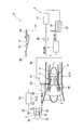
- 1 is a diagram illustrating an aircraft anti-icing system according to a first embodiment of the present invention. It is a figure which shows the structure which supplies a bleed air from this main machine to the warm air chamber of a blade
- FIG. 4 is a cross-sectional view taken along the line X1-X1 of FIG. It is a figure which shows the heat exchanger tube which the oil cooler of the anti-icing system of the aircraft which concerns on 1st Embodiment of this invention comprises. It is a figure which shows the anti-icing system of the aircraft which concerns on 2nd Embodiment of this invention.
- FIG. 1 It is a figure which shows a part of oil tank (tank main body, outer shell body, distribution space) of the anti-icing system for aircraft according to the second embodiment of the present invention. It is a figure which shows the anti-icing system of the aircraft which concerns on 3rd Embodiment of this invention.
- (A) is a figure which shows the distribution space (casing, outer-shell body, convex part) formed in the main machine of the anti-icing system of the aircraft which concerns on 3rd Embodiment of this invention
- (b) is A of (a). It is an arrow view.
- the aircraft 1 includes a main machine 3 provided on the main wing 2, a hydraulic pump 25 using the main machine 3 as a drive source, and a hydraulic circuit that operates with the hydraulic pump 25. 5, and a manifold 5 ′ for controlling the actuator 4 that forms part of the hydraulic circuit 5 and is provided on the main wing 2.
- the gas turbine 6, which is the main machine 3 includes a fan casing 7 and a core engine casing 8.
- the fan 9 is accommodated in the fan casing 7, and the compressor 10 and the combustion are in the core engine casing 8.
- the vessel 11 and the turbine 12 are accommodated.
- the fan 9 is formed by mounting a plurality of fan blades 16 on the outer periphery of the rotating shaft 15.
- the compressor 10 includes a low-pressure compressor 17 and a high-pressure compressor 18.
- the turbine 12 includes a high-pressure turbine 19 and a low-pressure turbine 20, and is disposed downstream of the compressor 10.
- the rotating shaft 15 of the fan 9 and the low-pressure compressor 17 are connected, and the low-pressure compressor 17 and the low-pressure turbine 20 are connected by a first rotor shaft 21.
- the high-pressure compressor 18 and the high-pressure turbine 19 are connected by a cylindrical second rotor shaft 22 located on the outer peripheral side of the first rotor shaft 21.
- the air taken in from the air intake port is compressed by passing through a plurality of stationary blades and moving blades (not shown) of the low pressure compressor 17 and the high pressure compressor 18 of the compressor 10, thereby compressing at a high temperature and a high pressure. It becomes air.
- a predetermined fuel is supplied to the compressed air by the combustor 11 and burned to generate a high-temperature and high-pressure combustion gas.
- the combustion gas thus generated passes through a plurality of stationary blades and moving blades (not shown) of the high-pressure turbine 19 and the low-pressure turbine 20 that constitute the turbine 12, so that the turbine 12 is rotationally driven.
- the power of the low-pressure turbine 20 is transmitted to the fan 9 by the first rotor shaft 21, and the fan 9 blows air to obtain thrust.
- the hydraulic circuit 5 of this embodiment supplies and discharges hydraulic oil to and from an actuator 4 for a steering system such as a flap, an aileron, a rudder, and a landing gear, and drives the actuator 4.
- a hydraulic pump 25 an oil cooler (heat exchanger) 26, and an oil tank 27.
- the hydraulic pump 25 is driven by the main machine and is installed in the main machine nacelle, and the oil cooler 26 and the oil tank 27 are installed in the lower part of the fuselage (machine body) 28.
- hydraulic oil is supplied from the oil tank 27 to the actuator 4 by driving the hydraulic pump 25, and the actuator 4 is driven and operated from the actuator 4.
- Oil (returned oil) is returned to the oil tank 27 through the oil cooler 26.
- the oil cooler 26 is formed by meandering a heat transfer pipe (hydraulic line) 30, and uses a low temperature outside air S 1 taken from an air intake 31 formed in the body 28 as a cooling medium, for example, 70 to 80 ° C.
- the return oil is cooled by returning heat to the oil tank 27 by exchanging heat between the high-temperature return oil and the outside air S ⁇ b> 1.
- the outside air S1 ′ heated by the heat source 26 of the machine body is selectively supplied to the warm air chamber 32 formed inside the blade leading edge 2a of the main wing 2 to perform ice prevention.
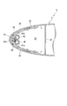
- the blade leading edge portion 2a of the main wing 2 is formed in a curved shape by joining upper and lower plate materials whose tip portions are curved, for example, as shown in FIGS.
- a guide plate 33 is disposed inside the blade leading edge 2a with a predetermined gap. Further, the guide plate 33 is formed in a curved shape by joining, for example, curved upper and lower plate materials, similarly to the blade leading edge portion 2a.
- the blade leading edge portion 2a indicates a portion including the vicinity of the leading edge of the blade 2.
- the wing leading edge 2a extends along the longitudinal direction of the main wing 2 (the vertical direction in FIG. 4), and the guide plate 33 has a predetermined length along the width direction of the aircraft 1, A plurality are arranged side by side in the direction. Further, the blade leading edge 2a is provided with a partition wall 34 along the longitudinal direction of the main wing 2 and along the longitudinal direction of the main wing 2 (the left-right direction in FIG. 3). It is formed at a predetermined interval in the longitudinal direction of the main wing 2. Further, each guide plate 33 is provided with its both end portions in contact with or fixed to the end face of the partition wall 34.
- the warm air chamber 32 is formed by being surrounded by the blade leading edge 2a, the rear partition wall 35, and the left and right partition walls 34.
- a space between the blade leading edge 2a and the guide plate 33 is a warm air passage 36.
- the warm air passage 36 extends along the inside of the blade leading edge 2a and extends rearward from the tip of the blade leading edge 2a. It is extended and opened to the warm air chamber 32.
- the warm air chamber 32 is provided with an exhaust port for appropriately discharging the air in the warm air chamber 32 to the outside.
- each of the duct pipes 40 and 41 is formed by closing both ends, and extends through the partition wall 34 along the longitudinal direction of the main wing 2.
- the guide plate 33 has an opening 33a at a position corresponding to the tip of the blade leading edge 2a.
- an injection hole 40a, 41a that opens toward the front of the blade leading edge 2a is formed at a position facing the opening 33a formed in the guide plate 33.
- the injection holes 40 a, 41 a are connected to the opening 33 a of the guide plate 33 through the connection pipes 42, 43.
- a plurality of openings 33a, injection holes 40a and 41a, and connecting pipes 42 and 43 are provided with a predetermined interval with respect to one guide plate 33.
- the two duct pipes 40 and 41 are individually connected to the opening 33a of the guide plate 33 via the connection pipes 42 and 43, that is, the injection holes 40a and 41a are individually connected to the warm air passage 36. Is provided.
- one duct pipe 40 is connected to the compressor 10 of the main machine 3 by a pipe (bleed air supply line) 45,
- the bleed air S2 of the compressor 10 of the main engine 3 is supplied from the bleed air supply line 45 to the warm air passage 36 (warm air chamber 32).
- the other duct pipe 41 is connected to the oil cooler 26 provided in the hydraulic circuit 5 by a pipe (temperature rising outside air supply line) 46.
- the meandering heat transfer pipe 30 of the oil cooler 26 is taken in from the air intake 31 and the inner pipe 47 through which the hydraulic oil discharged from the actuator 4 flows, as shown in FIGS.
- the outer pipe 48 is provided with an outer pipe 48 for allowing the outside air S1 to flow between the inner pipe 47 and the outer pipe S1.
- the inner tube 47 has a plurality of rings integrally attached thereto, and a convex portion 49 that protrudes from the outer surface of the inner tube 47 toward the inner surface of the outer tube 48 is formed by these rings.
- the other duct pipe 41 is connected to a circulation space 50 through which the outside air S1 between the inner pipe 47 and the outer pipe 48 of the heat transfer pipe 30 of the oil cooler 26 circulates via a temperature rising outside air supply line 46.
- the bleed air supply line 45 and the temperature rising outside air supply line 46 are provided with on-off valves 51 and 52, respectively.
- the valve controller 54 uses the valve controller 54 based on the measurement result of the thermometer 53 that measures the surface temperature (outside surface temperature or outside temperature) of the wing leading edge 2a of the main wing 2.
- the on-off valves 51 and 52 are controlled to open and close.
- a check valve for preventing air from flowing back from the warm air chamber 32 (warm air passage 36) to the main engine 3 and the oil cooler (heat source) 26 is provided in the bleed air supply line 45 and the temperature rising outside air supply line 46, respectively. Etc. (not shown) are provided.
- outside air S1 is taken in from the air intake 31 during navigation and is sent to the oil cooler 26 by ram pressure, and the operating oil is cooled by the oil cooler 26 using the outside air S1 as a cooling medium. Heat exchange is performed.
- the heat transfer tube 30 of the oil cooler 26 is formed in a double tube structure, and the outside air S ⁇ b> 1 flows in the distribution space 50 between the inner tube 47 and the outer tube 48.
- the low-temperature outside air S1 flows along the inner pipe 47 through which the high-temperature working oil flows through the circulation space 50 in this manner, so that heat exchange is efficiently performed between the working oil and the outside air S1.
- the outside air S1 rises in temperature.
- the heat transfer area of the inner tube 47 is increased. Heat exchange is promoted by the flow of the outside air S1 flowing through the circulation space 50 between the outer pipe 48 and the outer pipe 48 becoming a turbulent state. As a result, the heat exchange efficiency is increased, and the outside air S1 is heated reliably and efficiently.
- the outside air (warm air) S1 ′ heated by the oil cooler 26 is supplied to the other duct piping 41 of the warm air chamber 32 through the temperature rising outside air supply line 46, and is connected from the injection hole 41a of the other duct piping 41. It is injected into the warm air passage 36 between the blade leading edge 2 a and the guide plate 33 through the tube 43 and the opening 33 a of the guide plate 33.
- the heated outside air S1 ′ flows through the warm air passage 36, whereby the blade leading edge 2a is heated from the inside, preventing the ice from adhering to the outside of the blade 2 or removing the attached ice.
- the outside air S1 that has been conventionally taken out from the air intake 31 and used as a cooling medium for the oil cooler 26 is used for ice prevention.
- the bleed air S2 when the deicing can be sufficiently performed with the outside air S1 'heated by the oil cooler 26.
- the thermometer 53 detects a temperature at which ice prevention is sufficiently performed, the on-off valve 51 is closed by the control of the valve controller 54, but the on-off valve 52 is opened, so that only the outside air S1 'is in the other duct pipe 41.
- the valve controller 54 controls the opening and closing of the on-off valves 51 and 52, and the bleed air S2 from the main engine 3 enters the warm air passage 36 through the injection hole 40a of one duct pipe 40, the connecting pipe 42, and the opening 33a of the guide plate 33. Be injected. Since the bleed air S2 is hotter than the outside air S1 'heated by the oil cooler 26, the ice prevention is surely performed.
- the aircraft ice prevention system A it is possible to supply the bleed air S2 from the main engine 3 to the warm air chamber 32 in the same manner as in the past to perform ice prevention of the wing leading edge 2a. Then, the outside air S1 taken in from the air intake 31 provided in the machine body 28 is sent to the oil cooler 26 by the ram pressure to generate warm air (heated outside air) S1 ′.
- the outside air S1 taken from the air intake 31 is conventionally used as a cooling medium and the oil cooler 26 that discharges the outside air S1 ′ after heat exchange to the outside is used as a heat source.
- the heat generated by the navigation of the aircraft 1 is effectively used for deicing.
- the bleed air S2 and the outside air S1 ′ heated by the oil cooler 26 are selectively supplied to the warm air chamber 32 to perform deicing, and the outside air S1 ′ heated by the oil cooler 26 is sufficiently controlled.
- the bleed air S2 it is not necessary to use the bleed air S2.
- the ice prevention is surely performed by using the bleed air S2.
- the blade 2 can be kept warm with the heated outside air S1 ′ (the blade 2 can be preheated), and the ice is not easily attached. Therefore, the extraction amount of the bleed air S2 can be minimized.
- the bleed air S2 extracted from the main engine 3 is not required during navigation, or the bleed amount of the bleed air S2 is reduced to the minimum necessary amount. Therefore, compared with the case where the conventional anti-icing device is provided, the aircraft performance is improved such as the reduction of the main engine thrust and the reduction of the operation cost accompanying the improvement of the fuel consumption.
- the oil cooler 26 is configured so that the outside air S1 taken in from the air intake 31 is circulated between the outer tube 48 and the inner tube 47 of the heat transfer tube 30 having a double tube structure. As a result, the temperature of the outside air S1 is raised by heat exchange with the hydraulic oil that reliably flows through the inner pipe 47.
- the convex portion 49 is provided on the outer surface of the inner tube 47, the heat transfer area is increased, and when the outside air S1 flows between the outer tube 48 and the inner tube 47, the convex portion 49 flows.
- the heat exchange is promoted by the turbulent state. This makes it possible to increase the heat exchange efficiency between the hydraulic oil flowing through the inner pipe 47 and the outside air S1 flowing between the inner pipe 47 and the outer pipe 48, and the pipe length (transmission) in the oil cooler 26 can be increased. Reduce heat pipe length). And the weight of the aircraft 1 can be reduced by shortening the pipe length in the oil cooler 26 in this way.
- the aircraft ice prevention system of the present embodiment differs from the first embodiment only in the heat source that raises the temperature of the outside air mainly taken from the air intake. For this reason, the same components as those in the first embodiment are denoted by the same reference numerals, and detailed description thereof is omitted.
- the aircraft ice prevention system B includes bleed air S ⁇ b> 2 extracted from the main engine 3, and outside air taken in from the air intake 31 and heated by an oil tank (heat source of the aircraft fuselage) 27.
- S1 ′ is selectively supplied to the warm air chamber 32 formed inside the blade leading edge 2a of the main wing 2 to prevent ice removal.
- the oil tank 27 includes an outer shell body 56 that forms a circulation space 50 with the outer surface of the tank body 55 that stores hydraulic oil. Further, the tank body 55 includes a convex portion (convex piece) 57 on the outer surface.
- the other duct pipe 41 is connected to the oil tank 27 provided in the hydraulic circuit 5 by a temperature rising outside air supply line 46. At this time, the other duct pipe 41 is connected to the circulation space 50 through which the outside air S ⁇ b> 1 between the tank body 55 and the outer shell body 56 of the oil tank 27 circulates via the temperature rising outside air supply line 46.
- One duct pipe 40 is connected to the main engine 3 by a bleed air supply line 45 as in the first embodiment, and the bleed air S2 of the main machine 3 is connected from the one duct pipe 40 to the warm air passage 36 (warm air chamber 32). To supply.
- outside air S1 is taken in from the air intake 31 during navigation and is sent to the oil tank 27 by ram pressure.
- the tank body of the outside air S1 and the oil tank 27 Heat exchange is performed with the hydraulic oil temporarily stored in 55.
- the oil tank 27 is formed with the tank body 55 and the outer shell body 56, and the outside air S1 flows through the flow space 50 between the tank body 55 and the outer shell body 56.
- the outside air S1 flows along the outer surface of the tank body 55 that stores the working oil through the circulation space 50 in this way, so that heat is efficiently exchanged between the working oil and the outside air S1.
- S1 rises in temperature.
- the convex portion 57 is provided on the outer surface of the tank body 55, the heat transfer area of the tank body 55 is increased, and further, the circulation space 50 between the tank body 55 and the outer shell body 56. Heat exchange is promoted by the turbulent flow of the outside air S1 flowing through the air. Thereby, like the first embodiment, the heat exchange efficiency is increased, and the temperature of the outside air is reliably and efficiently raised.
- the outside air (warm air) S 1 ′ thus heated in the oil tank 27 is supplied to the other duct piping 41 of the warm air chamber 32 through the temperature rising outside air supply line 46 and connected from the injection hole 41 a of the other duct piping 41. It is injected into the warm air passage 36 between the blade leading edge 2 a and the guide plate 33 through the tube 43 and the opening 33 a of the guide plate 33.
- the heated outside air S1 ′ flows through the warm air passage 36, whereby the blade leading edge 2a is heated from the inside, preventing the ice from adhering to the outside of the blade 2 or removing the attached ice.
- the valve controller 54 controls the on-off valves 51 and 52 to open and close as in the first embodiment.
- the bleed air S ⁇ b> 2 is injected into the warm air passage 36 through the injection hole 40 a of the one duct pipe 40, the connecting pipe 42, and the opening 33 a of the guide plate 33.
- the bleed air S2 is higher in temperature than the outside air S1 'heated in the oil tank 27, so that the ice prevention is surely performed.
- the aircraft ice prevention system B of the present embodiment it is possible to supply the bleed air S2 from the main engine 3 to the warm air chamber 32 and perform ice prevention of the wing leading edge portion 2a, as in the first embodiment.
- the outside air S1 taken in from the air intake 31 provided in the machine body 28 is sent to the oil tank 27 by the ram pressure, and warm oil (heated outside air) S1 ′ is generated using the oil tank 27.
- the bleed air S2 extracted from the main engine 3 is not required during navigation, or the bleed amount of the bleed air S2 is the minimum necessary amount. Therefore, compared with the case where the conventional anti-icing device is provided, the aircraft performance is improved such as the reduction of the main engine thrust and the reduction of the operation cost accompanying the improvement of the fuel consumption.
- the aircraft ice prevention system C is bleed air S2 extracted from the main machine 3, and is taken in from the air intake 31 and lifted by the main machine 3 and the oil cooler 26 (heat source of the aircraft fuselage).
- the warm outside air S1 ′ is selectively supplied to a warm air chamber 32 formed inside the blade leading edge portion 2a of the main wing 2 to prevent ice removal.
- the outside air S1 taken from the air intake 31 is branched and sent to the oil cooler 26 and the main unit 3 by ram pressure, respectively, and the outside air S1 ′ heated at the oil cooler 26 and the main unit 3 is mixed. This is supplied to the other duct pipe 41 in the warm air chamber 32.
- oil cooler 26 of this embodiment is provided with the heat exchanger tube 30 of the double tube structure similarly to 1st Embodiment (refer FIG. 5).
- the casing of the combustor 11 is formed in a double cylinder structure. That is, as shown in FIG. 9, the cylindrical core engine casing 8 includes an outer shell body 60 that forms a flow space 50 between the outer surface of the core engine casing 8. Furthermore, in the portion provided with the outer shell body 60 (combustor 11 in this embodiment), first convex portions (convex portions) 61 such as fins are distributed and arranged on the entire outer surface of the core engine casing 8. ing.
- the first convex portion 61 is formed so as to protrude from the outer surface of the core engine casing 8 toward the inner surface of the outer shell body 60. That is, the tip of the first convex portion 61 is not in contact with the inner surface of the outer shell body 60.
- a plurality of second protrusions that protrude from the outer surface to the inner surface of the outer shell body 60 are provided on the outer surface of the core engine casing 8 including the outer shell body 60 in addition to the first protrusions 61.
- a portion (convex portion) 62 is provided. And these 2nd convex parts 62 are formed so that it may extend in the circumferential direction of the axis line O1 center of the core engine casing 8, and may go to the other end side gradually from the one end side in the direction of the axial line O1. Further, a predetermined gap is formed between the adjacent second convex portions 62. Accordingly, a spiral flow space 50 is formed between the second convex portions 62 adjacent in the direction of the axis O1.
- the other duct pipe 41 is connected to the oil cooler 26 and the main machine 3 via the temperature rising outside air supply line 46. At this time, the other duct pipe 41 is connected via the temperature rising outside air supply line 46.
- the circulation space 50 between the inner pipe 47 and the outer pipe 48 of the oil cooler 26 and the circulation space 50 between the core engine casing 8 and the outer shell body 60 of the main machine 3 are connected.
- One duct pipe 40 is connected to the main machine 3 by a bleed air supply line 45 as in the first and second embodiments, and the bleed air S2 of the main machine 3 is supplied from the one duct pipe 40 to the warm air passage 36. To do.
- the outside air S1 is taken from the air intake 31 and branched to be sent to the oil cooler 26 and the main engine 3 by ram pressure.
- the temperature is raised by heat exchange with an oil cooler, and the temperature is raised by heat exchange with the core engine casing 8 of the main engine 3.
- the outside air S1 flows through the plurality of distribution spaces 50 between the core engine casing 8 and the outer shell body 60.
- these circulation space 50 severe 2nd convex part 62
- the heat transfer area is increased by the second convex portion 62 and the first convex portion 61.
- the heat exchange is promoted by the turbulent flow of the outside air S1 flowing through each distribution space 50. Thereby, the heat transfer efficiency is increased, and the outside air temperature is reliably and efficiently raised.
- the outside air (warm air) S 1 ′ heated outside the core engine casing 8 of the main engine 3 is mixed with the outside air S 1 ′ heated by the oil cooler 26, and the other of the warm air chamber 32 through the temperature rising outside air supply line 46. Is supplied to the duct pipe 41. Then, the air is injected from the injection hole 41 a of the other duct pipe 41 into the warm air passage 36 between the blade leading edge 2 a and the guide plate 33 through the connection pipe 43 and the opening 33 a of the guide plate 33.
- the valve controller 54 controls opening / closing of the on-off valves 51, 52, and the bleed air S 2 from the main machine 3 is connected to the blade leading edge 2 a through the injection hole 40 a of one duct pipe 40, the connecting pipe 42, and the opening 33 a of the guide plate 33. It is injected into the warm air passage 36 between the guide plates 33. And since this bleed air S2 is higher temperature than the heated external air S1 ', ice prevention is reliably performed.
- the outside air S1 is circulated outside the core engine casing 8 of the main engine 3 to raise the temperature, so that the heat source is the oil cooler 26 of the hydraulic circuit 5, as in the first embodiment and the second embodiment.
- the engine 3 is designed so as not to cause a reduction in the thrust of the main machine 3, and the main air 3 is used as a heat source, so that the outside air S1 'supplied to the warm air chamber 32 is heated to a higher temperature. For this reason, compared with 1st Embodiment or 2nd Embodiment, the deicing prevention effect becomes high.
- the bleed air S2 is supplied from the main engine 3 to the warm air chamber 32 to perform ice prevention of the wing leading edge portion 2a, as in the first and second embodiments.
- the outside air S1 taken from the air intake 31 provided in the machine body 28 is sent to the main machine 3 (and the oil cooler 26) by the ram pressure, and warm air (heated outside air) S1 ′ is generated using the main machine 3.
- the bleed air S2 and the outside air S1 ′ heated by the main machine 3 are selectively supplied to the warm air chamber 32 to perform ice prevention ice, and the outside air S1 ′ heated by the main machine 3 sufficiently performs ice prevention ice removal. If this is possible, there is no need to use the bleed air S2. Further, when the outside air S1 'heated only by the main machine 3 is not sufficient, the ice prevention is surely performed by using the bleed air S2. Furthermore, even when this bleed air S2 is used, the blade 2 can be kept warm with the heated outside air S1 'in advance, and the amount of extraction of the bleed air S2 is minimized in order to keep the ice from sticking. Can be suppressed.
- the bleed air S2 extracted from the main engine 3 is not required during navigation, or the bleed amount of the bleed air S2 is the minimum necessary amount. Therefore, as compared with the case where the conventional anti-icing device is provided, the aircraft performance is improved, such as the reduction of the main engine thrust and the reduction of the operation cost accompanying the improvement of the fuel consumption.
- the first convex portion 61 such as a fin is provided on the outer surface of the core engine casing 8, thereby increasing the heat transfer area, and the outside air S ⁇ b> 1 is separated from the core engine casing 8.
- the first convex portion 61 makes the flow turbulent, thereby promoting heat exchange.
- the efficiency of heat exchange with the outside air S1 flowing through the circulation space 50 is increased, and the temperature of the outside air S1 is reliably and efficiently raised, and the raised outside air S1 'is effectively used for ice prevention.
- the 2nd convex part 62 is formed so that external air S1 may rotate and distribute
- the heat sources of the first, second, and third embodiments are selectively combined, and the oil cooler 26 and the oil tank 27,
- the outside air S ⁇ b> 1 taken from the air intake 31 may be heated by the oil tank 27 and the main unit 3, and the oil cooler 26, the oil tank 27 and the main unit 3, and supplied to the warm air chamber 32.
- the outside air S1 ′ raised from a plurality of heat sources is individually supplied to the warming chamber 32 (parallel type)
- the outside air S1 is gradually raised by the plurality of heat sources to the warming chamber 32. You may supply (series type).
- the bleed air S2 and the outside air S1 ′ heated by the heat source are supplied to the warm air chamber 32 formed at the blade leading edge portion 2a of the main wing 2 to the main wing 2.
- the warm air chamber 32 is formed on the tail wing and the like, and the warm air chamber 32 formed on the other wings by the ice prevention systems A, B, and C similar to the present embodiment ( The deicing effect may also be obtained by supplying the bleed air S2 or the outside air S1 ′ heated by the heat source to the warm air chamber 32 formed on another blade.
- the 1st convex part 61 and the spiral 2nd convex part 62 were provided and the distribution
- the temperature of the outside air S1 is raised by the main unit 3, it is not necessarily limited to the temperature rise of the outside air S1 by the combustor 11.
Landscapes
- Engineering & Computer Science (AREA)
- Aviation & Aerospace Engineering (AREA)
- Mechanical Engineering (AREA)
- General Engineering & Computer Science (AREA)
- Heat-Exchange Devices With Radiators And Conduit Assemblies (AREA)
- Structures Of Non-Positive Displacement Pumps (AREA)
- Fluid-Pressure Circuits (AREA)
- Lubrication Details And Ventilation Of Internal Combustion Engines (AREA)
Abstract
Description
本願は、2010年8月30日に日本に出願された特願2010-192618号について優先権を主張し、その内容をここに援用する。
以下、図1から図5を参照し、本発明の第1実施形態に係る航空機の防除氷システム及びこれを備える航空機について説明する。
次に、図1、図3から図7を参照し、本発明の第2実施形態に係る航空機の防除氷システム及びこれを備える航空機について説明する。本実施形態の航空機の防除氷システムは、第1実施形態に対して、主にエアインテークから取り込んだ外気を昇温させる熱源のみが異なる。このため、第1実施形態と同様の構成に対しては、同一符号を付してその詳細な説明を省略する。
次に、図1、図3から図5、図8、図9を参照し、本発明の第3実施形態に係る航空機の防除氷システム及びこれを備える航空機について説明する。本実施形態の航空機の防除氷システムでは、エアインテークから取り込んだ外気をオイルクーラーと主機で昇温し、第1実施形態及び第2実施形態と熱源が異なる。このため、本実施形態においても、第1実施形態及び第2実施形態と同様の構成に対しては、同一符号を付してその詳細な説明を省略する。
2 主翼(翼)
2a 翼前縁部
3 主機(熱源)
4 アクチュエータ
5 油圧回路
5’ マニホールド
6 ガスタービン
7 ファンケーシング
8 コアエンジンケーシング
9 ファン
10 圧縮機
11 燃焼器
12 タービン
15 回転軸
16 ファンブレード
17 低圧コンプレッサ
18 高圧コンプレッサ
19 高圧タービン
20 低圧タービン
21 第1ロータ軸
22 第2ロータ軸
25 油圧ポンプ
26 オイルクーラー(熱源)
27 オイルタンク(熱源)
28 胴体(機体)
30 伝熱管
31 エアインテーク
32 暖気室
33 ガイド板
33a 開口部
34 隔壁
35 隔壁
36 暖気通路
40 ダクト配管
40a 噴射孔
41 ダクト配管
41a 噴射孔
42 連結管
43 連結管
45 ブリードエア供給ライン
46 昇温外気供給ライン
47 内管
48 外管
49 凸部
50 流通空間
51 開閉弁
52 開閉弁
53 温度計
54 バルブコントローラ
55 タンク本体
56 外殻体
60 外殻体
61 第1凸部(凸部)
62 第2凸部(凸部)
A 航空機の防除氷システム
B 航空機の防除氷システム
C 航空機の防除氷システム
S1 外気
S1’ 昇温した外気
S2 ブリードエア
Claims (11)
- 航空機の翼に氷が付着することを防止、あるいは付着した氷を除去するための防除氷システムであって、
航空機の翼の内側に形成された暖気室と、
前記航空機の主機から抽気されたブリードエアを、前記暖気室に供給するためのブリードエア供給ラインと、
前記航空機のエアインテークから取り込まれた外気を、前記航空機の熱源を介して前記暖気室に供給するための昇温外気供給ラインと、
前記ブリードエアと前記熱源によって加熱された外気とを、前記暖気室に選択的に供給するための切換手段と、
を備え、
前記暖気室に供給された空気によって、前記翼を暖めて防除氷する防除氷システム。 - 請求項1記載の航空機の防除氷システムにおいて、前記熱源が、航空機に設けられた油圧回路に具備されたオイルクーラー、オイルタンク、または、航空機の主機の少なくとも一つである航空機の防除氷システム。
- 請求項2記載の航空機の防除氷システムにおいて、前記オイルクーラーは、作動油が流通する内管と、前記エアインテークから取り込んだ前記外気を前記内管との間で流通させる外管とからなる二重管構造の伝熱管を備え、前記内管を流通する作動油との熱交換によって前記外気を昇温させる航空機の防除氷システム。
- 請求項3記載の航空機の防除氷システムにおいて、前記内管が外面に凸部を備えている航空機の防除氷システム。
- 請求項2から請求項4のいずれか一項に記載の航空機の防除氷システムにおいて、前記オイルタンクは、作動油を貯留するタンク本体の外面との間に流通空間を形成する外殻体を備え、前記タンク本体内の作動油との熱交換によって、前記流通空間を流通する前記外気を昇温させる航空機の防除氷システム。
- 請求項5記載の航空機の防除氷システムにおいて、前記タンク本体が外面に凸部を備えている航空機の防除氷システム。
- 請求項2から請求項6のいずれか一項に記載の航空機の防除氷システムにおいて、前記主機は、ケーシングの外面との間に流通空間を形成する外殻体を備え、前記外気を前記流通空間に流通させることにより昇温させる航空機の防除氷システム。
- 請求項7記載の航空機の防除氷システムにおいて、前記ケーシングの外面に凸部を備えている航空機の防除氷システム。
- 請求項8記載の航空機の防除氷システムにおいて、前記ケーシングの外面の凸部は、前記外気を前記ケーシングの外面に沿って旋回して流通させるように形成されている航空機の防除氷システム。
- 請求項1から請求項9のいずれか一項に記載の防除氷システムであって、前記切換手段は、前記ブリードエア供給ラインに設けられた第一開閉弁と、前記昇温外気供給ラインに設けられた第二開閉弁と、前記第一、第二開閉弁の作動を制御する制御部と、を含む防除氷システム。
- 請求項1から請求項10のいずれかに記載の航空機の防除氷システムを備えた航空機。
Priority Applications (6)
| Application Number | Priority Date | Filing Date | Title |
|---|---|---|---|
| CA2808362A CA2808362C (en) | 2010-08-30 | 2011-08-30 | Aircraft ice protection system and aircraft provided with the same |
| CN201180039942.5A CN103068679B (zh) | 2010-08-30 | 2011-08-30 | 航空器的防除冰系统及具备该系统的航空器 |
| EP11821798.3A EP2612814B1 (en) | 2010-08-30 | 2011-08-30 | Aircraft ice protection system and aircraft provided with same |
| US13/816,562 US8967543B2 (en) | 2010-08-30 | 2011-08-30 | Aircraft ice protection system and aircraft provided with the same |
| RU2013106192/11A RU2529927C1 (ru) | 2010-08-30 | 2011-08-30 | Противообледенительная система летательного аппарата и летательный аппарат, оснащенный указанной системой |
| BR112013003732-6A BR112013003732A2 (pt) | 2010-08-30 | 2011-08-30 | sistema de proteção contra gelo para aeronave, e, aeronave |
Applications Claiming Priority (2)
| Application Number | Priority Date | Filing Date | Title |
|---|---|---|---|
| JP2010192618A JP5582927B2 (ja) | 2010-08-30 | 2010-08-30 | 航空機の防除氷システム及びこれを備える航空機 |
| JP2010-192618 | 2010-08-30 |
Publications (1)
| Publication Number | Publication Date |
|---|---|
| WO2012029782A1 true WO2012029782A1 (ja) | 2012-03-08 |
Family
ID=45772864
Family Applications (1)
| Application Number | Title | Priority Date | Filing Date |
|---|---|---|---|
| PCT/JP2011/069609 Ceased WO2012029782A1 (ja) | 2010-08-30 | 2011-08-30 | 航空機の防除氷システム及びこれを備える航空機 |
Country Status (8)
| Country | Link |
|---|---|
| US (1) | US8967543B2 (ja) |
| EP (1) | EP2612814B1 (ja) |
| JP (1) | JP5582927B2 (ja) |
| CN (1) | CN103068679B (ja) |
| BR (1) | BR112013003732A2 (ja) |
| CA (1) | CA2808362C (ja) |
| RU (1) | RU2529927C1 (ja) |
| WO (1) | WO2012029782A1 (ja) |
Cited By (2)
| Publication number | Priority date | Publication date | Assignee | Title |
|---|---|---|---|---|
| JP2016533955A (ja) * | 2013-08-19 | 2016-11-04 | ザ・ボーイング・カンパニーThe Boeing Company | 抽気ダクトから廃エネルギーを回復するための方法 |
| RU2840467C1 (ru) * | 2024-09-09 | 2025-05-26 | Федеральное государственное казенное военное образовательное учреждение высшего образования "Военный учебно-научный центр Военно-воздушных сил "Военно-воздушная академия имени профессора Н.Е. Жуковского и Ю.А. Гагарина" (г. Воронеж) Министерства обороны Российской Федерации | Устройство защиты от обледенения крыла летательного аппарата |
Families Citing this family (35)
| Publication number | Priority date | Publication date | Assignee | Title |
|---|---|---|---|---|
| JP5582927B2 (ja) * | 2010-08-30 | 2014-09-03 | 三菱重工業株式会社 | 航空機の防除氷システム及びこれを備える航空機 |
| US9429072B2 (en) * | 2013-05-22 | 2016-08-30 | General Electric Company | Return fluid air cooler system for turbine cooling with optional power extraction |
| FR3007738B1 (fr) * | 2013-06-28 | 2015-07-31 | Aircelle Sa | Dispositif de degivrage et de conditionnement pour aeronef |
| US9764847B2 (en) * | 2013-10-18 | 2017-09-19 | The Boeing Company | Anti-icing system for aircraft |
| EP3018304B1 (en) * | 2014-11-06 | 2020-10-14 | United Technologies Corporation | Thermal management system for a gas turbine engine |
| EP3045699B1 (en) * | 2015-01-14 | 2018-10-03 | Goodrich Actuation Systems Limited | Anti-icing systems |
| CN104787344A (zh) * | 2015-04-23 | 2015-07-22 | 四川正冠科技有限公司 | 一种飞机表面自动加热装置 |
| CN104787343A (zh) * | 2015-04-23 | 2015-07-22 | 四川正冠科技有限公司 | 一种飞机表面加热器 |
| RU2604921C2 (ru) * | 2015-05-06 | 2016-12-20 | Публичное акционерное Общество "Таганрогский авиационный научно-технический комплекс им. Г.М. Бериева" (ПАО "ТАНТК им. Г.М. Бериева") | Способ удаления льда и снега с поверхности самолета |
| US11214381B2 (en) * | 2015-08-07 | 2022-01-04 | Pratt & Whitney Canada Corp. | Aircraft heating assembly with liquid cooled internal combustion engine and heating element using waste heat |
| JP6661369B2 (ja) | 2015-12-25 | 2020-03-11 | 三菱航空機株式会社 | 航空機の高温ダクトと構造部材との挟入シート、航空機のダクト構造、および航空機 |
| US10167085B2 (en) | 2016-01-27 | 2019-01-01 | General Electric Company | Nozzle and vane system for nacelle anti-icing |
| JP2017136893A (ja) * | 2016-02-01 | 2017-08-10 | 三菱航空機株式会社 | 防氷装置、及び、航空機 |
| US10513978B2 (en) | 2016-05-02 | 2019-12-24 | General Electric Company | Directed flow nozzle swirl enhancer |
| US10737792B2 (en) * | 2016-09-22 | 2020-08-11 | The Boeing Company | Turbofan engine fluid ice protection delivery system |
| CN107764574B (zh) * | 2017-09-08 | 2021-09-14 | 中国飞行试验研究院 | 一种推进式航空螺旋桨防冰功能验证试飞测试方法 |
| US10655539B2 (en) * | 2017-10-16 | 2020-05-19 | Rolls-Royce North America Technologies Inc. | Aircraft anti-icing system |
| CN107745828A (zh) * | 2017-11-28 | 2018-03-02 | 中国航空工业集团公司沈阳空气动力研究所 | 一种热气防除冰试验引气装置 |
| US20190359341A1 (en) * | 2018-05-25 | 2019-11-28 | The Boeing Company | Method of thermal ice protection for an aircraft wing |
| US11130582B2 (en) | 2018-08-03 | 2021-09-28 | Rolls-Royce Corporation | Systems and methods of optimizing cooling and providing useful heating from single phase and two phase heat management in propulsion systems |
| RU2712103C1 (ru) * | 2019-04-12 | 2020-01-24 | Федеральное государственное унитарное предприятие "Центральный институт авиационного моторостроения имени П.И. Баранова" | Способ управления противообледенительной системой турбореактивного двухконтурного двигателя |
| US11299280B2 (en) * | 2019-07-24 | 2022-04-12 | The Boeing Company | Leading-edge thermal anti-ice systems and methods |
| RU2747853C2 (ru) * | 2019-10-04 | 2021-05-17 | Публичное акционерное общество "Научно-производственная корпорация "Иркут" | Способ защиты крыла самолёта от обледенения и система защиты |
| RU2748665C1 (ru) * | 2020-09-28 | 2021-05-28 | федеральное государственное автономное образовательное учреждение высшего образования "Пермский национальный исследовательский политехнический университет" | Способ удаления обледенения на аэродинамических поверхностях |
| CN114112354A (zh) * | 2021-11-19 | 2022-03-01 | 中国直升机设计研究所 | 一种直升机进气道防冰系统的试验方法 |
| CN115234374B (zh) * | 2022-07-26 | 2025-06-17 | 中国航发沈阳发动机研究所 | 一种空天飞机发动机进气道进口射流预冷结构 |
| US12428992B2 (en) | 2022-11-01 | 2025-09-30 | General Electric Company | Gas turbine engine |
| US12196131B2 (en) | 2022-11-01 | 2025-01-14 | General Electric Company | Gas turbine engine |
| US12410753B2 (en) | 2022-11-01 | 2025-09-09 | General Electric Company | Gas turbine engine |
| US12503980B2 (en) | 2022-11-01 | 2025-12-23 | General Electric Company | Gas turbine engine |
| US12392290B2 (en) | 2022-11-01 | 2025-08-19 | General Electric Company | Gas turbine engine |
| US12535033B2 (en) | 2022-11-01 | 2026-01-27 | General Electric Company | Gas turbine engine |
| DE102025122365A1 (de) * | 2024-06-12 | 2025-12-18 | Eaton Intelligent Power Limited | Eisschutzsystem mit abwärmerückgewinnung |
| KR102860628B1 (ko) * | 2024-12-03 | 2025-09-16 | 경상국립대학교산학협력단 | 연료전지 방열을 이용한 항공기 결빙 방지 시스템 및 방법 |
| US12540551B1 (en) | 2025-07-01 | 2026-02-03 | General Electric Company | Gas turbine engines including splittered airfoils |
Citations (8)
| Publication number | Priority date | Publication date | Assignee | Title |
|---|---|---|---|---|
| JPH01149894A (ja) | 1987-12-07 | 1989-06-12 | Kanebo Ltd | 成型炭 |
| JPH01149894U (ja) * | 1988-04-08 | 1989-10-17 | ||
| JPH06206593A (ja) | 1993-01-08 | 1994-07-26 | Mitsubishi Heavy Ind Ltd | 航空機の防除氷装置 |
| US6196500B1 (en) * | 1996-06-19 | 2001-03-06 | Cox & Company, Inc. | Hybrid ice protection system for use on roughness-sensitive airfoils |
| JP3529911B2 (ja) * | 1995-09-05 | 2004-05-24 | 本田技研工業株式会社 | 航空機の前縁構造及び前縁部の製造方法 |
| JP2008521693A (ja) * | 2004-12-03 | 2008-06-26 | エアバス・ドイチュラント・ゲーエムベーハー | 航空機におけるエネルギー供給のための供給システム、航空機、及びエネルギーを航空機に供給する方法 |
| WO2009127652A2 (de) * | 2008-04-16 | 2009-10-22 | Airbus Operations Gmbh | Enteisungssystem für ein flugzeug |
| JP2010100285A (ja) * | 2002-10-22 | 2010-05-06 | Boeing Co:The | 航空機用の電気ベースの2次動力システムアーキテクチャ |
Family Cites Families (58)
| Publication number | Priority date | Publication date | Assignee | Title |
|---|---|---|---|---|
| US2581760A (en) * | 1946-04-02 | 1952-01-08 | Douglas Aircraft Co Inc | Airplane deicing construction |
| US3449891A (en) * | 1966-11-15 | 1969-06-17 | United Aircraft Corp | Engine inlet air particle separator |
| US3441236A (en) * | 1967-01-16 | 1969-04-29 | Eric Arnholdt | Airfoil |
| US3576329A (en) * | 1968-11-26 | 1971-04-27 | Cement Asbestos Products Co | Pipe packing joint with gasket providing combined deformation and lip seals |
| US3925979A (en) * | 1973-10-29 | 1975-12-16 | Gen Electric | Anti-icing system for a gas turbine engine |
| US3917193A (en) * | 1974-01-21 | 1975-11-04 | Boeing Co | Boundary layer control and anti-icing apparatus for an aircraft wing |
| JPS58156499A (ja) | 1982-03-13 | 1983-09-17 | 住友電気工業株式会社 | 飛行機の除氷装置 |
| US4688745A (en) * | 1986-01-24 | 1987-08-25 | Rohr Industries, Inc. | Swirl anti-ice system |
| US4738416A (en) * | 1986-09-26 | 1988-04-19 | Quiet Nacelle Corporation | Nacelle anti-icing system |
| US5011098A (en) * | 1988-12-30 | 1991-04-30 | The Boeing Company | Thermal anti-icing system for aircraft |
| US5114100A (en) * | 1989-12-29 | 1992-05-19 | The Boeing Company | Anti-icing system for aircraft |
| GB9120113D0 (en) * | 1991-09-20 | 1992-09-23 | Short Brothers Plc | Thermal antiicing of aircraft structures |
| US5782435A (en) * | 1995-05-24 | 1998-07-21 | Cox & Company, Inc. | Electro-magnetic expulsion de-icing system |
| JP3529910B2 (ja) | 1995-09-05 | 2004-05-24 | 本田技研工業株式会社 | 航空機の前縁構造及びその製造方法 |
| US5807454A (en) * | 1995-09-05 | 1998-09-15 | Honda Giken Kogyo Kabushiki Kaisha | Method of maufacturing a leading edge structure for aircraft |
| US6003814A (en) * | 1996-06-17 | 1999-12-21 | Seniors Flexonics Inc. Stainless Steel Products Division | Double-walled duct assembly for aircraft anti-icing conduit systems |
| JP3647612B2 (ja) | 1997-07-24 | 2005-05-18 | 富士重工業株式会社 | 航空機の前縁構造及びその製造方法 |
| US5841079A (en) * | 1997-11-03 | 1998-11-24 | Northrop Grumman Corporation | Combined acoustic and anti-ice engine inlet liner |
| FR2772341B1 (fr) * | 1997-12-12 | 2000-03-24 | Aerospatiale | Diffuseur d'air chaud pour capot d'entree d'air de moteur a reaction a circuit de degivrage |
| US6267328B1 (en) * | 1999-10-21 | 2001-07-31 | Rohr, Inc. | Hot air injection for swirling rotational anti-icing system |
| US6354538B1 (en) * | 1999-10-25 | 2002-03-12 | Rohr, Inc. | Passive control of hot air injection for swirling rotational type anti-icing system |
| US6371411B1 (en) * | 1999-11-23 | 2002-04-16 | The Boeing Company | Method and apparatus for aircraft inlet ice protection |
| US6688558B2 (en) * | 1999-11-23 | 2004-02-10 | The Boeing Company | Method and apparatus for aircraft inlet ice protection |
| FR2813581B1 (fr) * | 2000-09-06 | 2002-11-29 | Aerospatiale Matra Airbus | Capot d'entree d'air de moteur a reaction pourvu de moyens de degivrage |
| US6702233B1 (en) * | 2001-02-07 | 2004-03-09 | Rohr, Inc. | Airfoil anti-icing assembly and method |
| FR2820715B1 (fr) * | 2001-02-15 | 2003-05-30 | Eads Airbus Sa | Procede de degivrage d'un capot d'entree d'air de moteur a reaction et dispositif pour sa mise en oeuvre |
| AU2002250133A1 (en) * | 2001-02-16 | 2002-09-04 | Hamilton Sundstrand Corporation | Improved aircraft system architecture |
| FR2823533B1 (fr) * | 2001-04-17 | 2003-08-08 | Eads Airbus Sa | Capot d'entree d'air pour moteur a reaction, pourvu de moyens de degivrage |
| US6698687B2 (en) * | 2002-02-13 | 2004-03-02 | The Boeing Company | Aircraft wing heat exchanger apparatus and method |
| JP3973474B2 (ja) | 2002-04-05 | 2007-09-12 | 日本飛行機株式会社 | 航空機翼前縁部の製造方法 |
| GB0211800D0 (en) * | 2002-05-22 | 2002-07-03 | Short Brothers Plc | An ice protection system for aircraft structures |
| DE10361655B4 (de) * | 2003-12-30 | 2007-10-04 | Airbus Deutschland Gmbh | Vorrichtung und Verfahren zur Fußbodenheizung in einem Flugzeug |
| US20060032983A1 (en) * | 2004-07-19 | 2006-02-16 | Brand Joseph H | Foreign object damage tolerant nacelle anti-icing system |
| DE502006001066D1 (de) * | 2006-01-05 | 2008-08-21 | Norma Germany Gmbh | Verbindungsanordnung mit Rohrstutzen zum Verbinden von Fluidaufnahmeteilen |
| US7708227B2 (en) * | 2006-01-06 | 2010-05-04 | Cox & Company, Inc. | Energy-efficient electro-thermal ice-protection system |
| FR2896228B1 (fr) | 2006-01-16 | 2008-02-15 | Airbus France Sas | Procede de degivrage du bord d'attaque d'une surface aerodynamique et aeronef mettant en oeuvre un tel procede. |
| EP2004488B1 (en) * | 2006-03-17 | 2012-04-25 | Ultra Electronics Limited | Ice protection system |
| US7779866B2 (en) * | 2006-07-21 | 2010-08-24 | General Electric Company | Segmented trapped vortex cavity |
| US7575196B2 (en) * | 2006-12-19 | 2009-08-18 | Honeywell International Inc. | Ice protection system and method including a plurality of segmented sub-areas and a cyclic diverter valve |
| JP2008309059A (ja) | 2007-06-14 | 2008-12-25 | Ihi Corp | タービンケーシングの冷却構造 |
| US20090108134A1 (en) * | 2007-10-25 | 2009-04-30 | General Electric Company | Icing protection system and method for enhancing heat transfer |
| FR2924409B1 (fr) * | 2007-12-03 | 2010-05-14 | Airbus France | Nacelle d'aeronef comprenant des moyens d'evacuations d'air chaud |
| FR2924407B1 (fr) * | 2007-12-03 | 2010-05-14 | Airbus France | Systeme de sortie d'air pour un bord d'attaque d'aeronef |
| US7900872B2 (en) * | 2007-12-12 | 2011-03-08 | Spirit Aerosystems, Inc. | Nacelle inlet thermal anti-icing spray duct support system |
| DE102008007278B4 (de) * | 2008-02-01 | 2010-04-08 | Airbus Deutschland Gmbh | Bleedairduct-Segment, Bleedairduct-Anordnung mit solchen Bleedairduct-Segmenten und Bleedairduct-System mit Regulierungsvorrichtung |
| US7975966B2 (en) | 2008-02-04 | 2011-07-12 | Embraer - Empresa Brasileira De Aeronautica S.A. | Icing protection for aircraft air inlet scoops |
| FR2927882B1 (fr) * | 2008-02-27 | 2010-02-12 | Aircelle Sa | Structure d'entree d'air pour une nacelle d'un aeronef |
| US8052089B2 (en) * | 2008-11-03 | 2011-11-08 | The Boeing Company | Anti-icing apparatus for honeycomb structures |
| US8061657B2 (en) * | 2008-12-31 | 2011-11-22 | General Electric Company | Method and apparatus for aircraft anti-icing |
| US8100364B2 (en) * | 2009-01-15 | 2012-01-24 | Textron Innovations Inc. | Anti-icing piccolo tube standoff |
| FR2953811B1 (fr) * | 2009-12-15 | 2012-03-16 | Airbus Operations Sas | Panneau pour une entree d'air d'une nacelle d'aeronef assurant un traitement acoustique et un traitement du givre optimises |
| FR2954280B1 (fr) * | 2009-12-18 | 2012-03-23 | Airbus Operations Sas | Entree d'air d'une nacelle d'aeronef comprenant un traitement du givre optimise |
| FR2954279B1 (fr) * | 2009-12-18 | 2014-08-22 | Airbus Operations Sas | Entree d'air d'une nacelle d'aeronef integrant des moyens d'injection en air chaud pour le traitement du givre optimises |
| JP2011183922A (ja) * | 2010-03-08 | 2011-09-22 | Mitsubishi Heavy Ind Ltd | 航空機における翼前縁部の防除氷装置及び航空機主翼 |
| JP5582927B2 (ja) * | 2010-08-30 | 2014-09-03 | 三菱重工業株式会社 | 航空機の防除氷システム及びこれを備える航空機 |
| US8430359B2 (en) * | 2010-10-18 | 2013-04-30 | Cox & Company, Inc. | Energy-efficient electro-thermal and electro-mechanical ice-protection method |
| GB201101335D0 (en) * | 2011-01-26 | 2011-03-09 | Airbus Uk Ltd | Aircraft slat assembly with anti-icing system |
| DE102011102458A1 (de) * | 2011-05-24 | 2012-11-29 | Rolls-Royce Deutschland Ltd & Co Kg | Enteisungsvorrichtung eines Fluggasturbinentriebwerks |
-
2010
- 2010-08-30 JP JP2010192618A patent/JP5582927B2/ja not_active Expired - Fee Related
-
2011
- 2011-08-30 CN CN201180039942.5A patent/CN103068679B/zh not_active Expired - Fee Related
- 2011-08-30 WO PCT/JP2011/069609 patent/WO2012029782A1/ja not_active Ceased
- 2011-08-30 BR BR112013003732-6A patent/BR112013003732A2/pt not_active Application Discontinuation
- 2011-08-30 CA CA2808362A patent/CA2808362C/en not_active Expired - Fee Related
- 2011-08-30 RU RU2013106192/11A patent/RU2529927C1/ru not_active IP Right Cessation
- 2011-08-30 EP EP11821798.3A patent/EP2612814B1/en not_active Not-in-force
- 2011-08-30 US US13/816,562 patent/US8967543B2/en not_active Expired - Fee Related
Patent Citations (8)
| Publication number | Priority date | Publication date | Assignee | Title |
|---|---|---|---|---|
| JPH01149894A (ja) | 1987-12-07 | 1989-06-12 | Kanebo Ltd | 成型炭 |
| JPH01149894U (ja) * | 1988-04-08 | 1989-10-17 | ||
| JPH06206593A (ja) | 1993-01-08 | 1994-07-26 | Mitsubishi Heavy Ind Ltd | 航空機の防除氷装置 |
| JP3529911B2 (ja) * | 1995-09-05 | 2004-05-24 | 本田技研工業株式会社 | 航空機の前縁構造及び前縁部の製造方法 |
| US6196500B1 (en) * | 1996-06-19 | 2001-03-06 | Cox & Company, Inc. | Hybrid ice protection system for use on roughness-sensitive airfoils |
| JP2010100285A (ja) * | 2002-10-22 | 2010-05-06 | Boeing Co:The | 航空機用の電気ベースの2次動力システムアーキテクチャ |
| JP2008521693A (ja) * | 2004-12-03 | 2008-06-26 | エアバス・ドイチュラント・ゲーエムベーハー | 航空機におけるエネルギー供給のための供給システム、航空機、及びエネルギーを航空機に供給する方法 |
| WO2009127652A2 (de) * | 2008-04-16 | 2009-10-22 | Airbus Operations Gmbh | Enteisungssystem für ein flugzeug |
Cited By (2)
| Publication number | Priority date | Publication date | Assignee | Title |
|---|---|---|---|---|
| JP2016533955A (ja) * | 2013-08-19 | 2016-11-04 | ザ・ボーイング・カンパニーThe Boeing Company | 抽気ダクトから廃エネルギーを回復するための方法 |
| RU2840467C1 (ru) * | 2024-09-09 | 2025-05-26 | Федеральное государственное казенное военное образовательное учреждение высшего образования "Военный учебно-научный центр Военно-воздушных сил "Военно-воздушная академия имени профессора Н.Е. Жуковского и Ю.А. Гагарина" (г. Воронеж) Министерства обороны Российской Федерации | Устройство защиты от обледенения крыла летательного аппарата |
Also Published As
| Publication number | Publication date |
|---|---|
| JP5582927B2 (ja) | 2014-09-03 |
| RU2529927C1 (ru) | 2014-10-10 |
| CN103068679B (zh) | 2016-08-24 |
| BR112013003732A2 (pt) | 2020-06-30 |
| EP2612814A1 (en) | 2013-07-10 |
| EP2612814A4 (en) | 2017-11-01 |
| CA2808362A1 (en) | 2012-03-08 |
| US20130195658A1 (en) | 2013-08-01 |
| CA2808362C (en) | 2015-02-17 |
| JP2012046151A (ja) | 2012-03-08 |
| RU2013106192A (ru) | 2014-10-10 |
| EP2612814B1 (en) | 2019-04-24 |
| CN103068679A (zh) | 2013-04-24 |
| US8967543B2 (en) | 2015-03-03 |
Similar Documents
| Publication | Publication Date | Title |
|---|---|---|
| JP5582927B2 (ja) | 航空機の防除氷システム及びこれを備える航空機 | |
| US11029103B2 (en) | Dual seated by-pass valve for surface coolers | |
| EP2990335B1 (en) | Gas turbine engine | |
| US20160114898A1 (en) | Circuit for de-icing an air inlet lip of an aircraft propulsion assembly | |
| US10294822B2 (en) | Turbine engine nacelle fitted with a heat exchanger | |
| JP6259219B2 (ja) | 熱交換器組立体およびガスタービンエンジン組立体 | |
| CN108137163B (zh) | 具有液体冷却的内燃机和利用废热的加热元件的飞行器加热组件 | |
| US9038397B2 (en) | Gas turbine engine thermal management system | |
| US20160115864A1 (en) | Conformal surface heat exchanger for aircraft | |
| KR101619278B1 (ko) | 냉각수 제어밸브를 갖는 엔진시스템 | |
| CN113914945A (zh) | 热管理系统 | |
| US20150291284A1 (en) | De-icing system with thermal management | |
| US20180038280A1 (en) | Turbomachine comprising a heat management system | |
| CN105339263A (zh) | 用于飞行器的除冰及调节设备 | |
| RU2659426C1 (ru) | Газотурбинная силовая установка летательного аппарата | |
| CN111502813B (zh) | 具有热管理系统的发动机组件 |
Legal Events
| Date | Code | Title | Description |
|---|---|---|---|
| WWE | Wipo information: entry into national phase |
Ref document number: 201180039942.5 Country of ref document: CN |
|
| 121 | Ep: the epo has been informed by wipo that ep was designated in this application |
Ref document number: 11821798 Country of ref document: EP Kind code of ref document: A1 |
|
| ENP | Entry into the national phase |
Ref document number: 2808362 Country of ref document: CA |
|
| WWE | Wipo information: entry into national phase |
Ref document number: 2011821798 Country of ref document: EP |
|
| NENP | Non-entry into the national phase |
Ref country code: DE |
|
| WWE | Wipo information: entry into national phase |
Ref document number: 13816562 Country of ref document: US |
|
| ENP | Entry into the national phase |
Ref document number: 2013106192 Country of ref document: RU Kind code of ref document: A |
|
| REG | Reference to national code |
Ref country code: BR Ref legal event code: B01A Ref document number: 112013003732 Country of ref document: BR |
|
| ENP | Entry into the national phase |
Ref document number: 112013003732 Country of ref document: BR Kind code of ref document: A2 Effective date: 20130218 |