WO2012060175A1 - 酸化物触媒、酸化物触媒の製造方法、不飽和酸の製造方法及び不飽和ニトリルの製造方法 - Google Patents
酸化物触媒、酸化物触媒の製造方法、不飽和酸の製造方法及び不飽和ニトリルの製造方法 Download PDFInfo
- Publication number
- WO2012060175A1 WO2012060175A1 PCT/JP2011/072781 JP2011072781W WO2012060175A1 WO 2012060175 A1 WO2012060175 A1 WO 2012060175A1 JP 2011072781 W JP2011072781 W JP 2011072781W WO 2012060175 A1 WO2012060175 A1 WO 2012060175A1
- Authority
- WO
- WIPO (PCT)
- Prior art keywords
- catalyst
- oxide catalyst
- firing
- temperature
- dry powder
- Prior art date
- Legal status (The legal status is an assumption and is not a legal conclusion. Google has not performed a legal analysis and makes no representation as to the accuracy of the status listed.)
- Ceased
Links
Images
Classifications
-
- B—PERFORMING OPERATIONS; TRANSPORTING
- B01—PHYSICAL OR CHEMICAL PROCESSES OR APPARATUS IN GENERAL
- B01J—CHEMICAL OR PHYSICAL PROCESSES, e.g. CATALYSIS OR COLLOID CHEMISTRY; THEIR RELEVANT APPARATUS
- B01J23/00—Catalysts comprising metals or metal oxides or hydroxides, not provided for in group B01J21/00
- B01J23/38—Catalysts comprising metals or metal oxides or hydroxides, not provided for in group B01J21/00 of noble metals
- B01J23/54—Catalysts comprising metals or metal oxides or hydroxides, not provided for in group B01J21/00 of noble metals combined with metals, oxides or hydroxides provided for in groups B01J23/02 - B01J23/36
-
- B—PERFORMING OPERATIONS; TRANSPORTING
- B01—PHYSICAL OR CHEMICAL PROCESSES OR APPARATUS IN GENERAL
- B01J—CHEMICAL OR PHYSICAL PROCESSES, e.g. CATALYSIS OR COLLOID CHEMISTRY; THEIR RELEVANT APPARATUS
- B01J23/00—Catalysts comprising metals or metal oxides or hydroxides, not provided for in group B01J21/00
- B01J23/16—Catalysts comprising metals or metal oxides or hydroxides, not provided for in group B01J21/00 of arsenic, antimony, bismuth, vanadium, niobium, tantalum, polonium, chromium, molybdenum, tungsten, manganese, technetium or rhenium
- B01J23/24—Chromium, molybdenum or tungsten
- B01J23/30—Tungsten
-
- B—PERFORMING OPERATIONS; TRANSPORTING
- B01—PHYSICAL OR CHEMICAL PROCESSES OR APPARATUS IN GENERAL
- B01J—CHEMICAL OR PHYSICAL PROCESSES, e.g. CATALYSIS OR COLLOID CHEMISTRY; THEIR RELEVANT APPARATUS
- B01J23/00—Catalysts comprising metals or metal oxides or hydroxides, not provided for in group B01J21/00
- B01J23/70—Catalysts comprising metals or metal oxides or hydroxides, not provided for in group B01J21/00 of the iron group metals or copper
- B01J23/76—Catalysts comprising metals or metal oxides or hydroxides, not provided for in group B01J21/00 of the iron group metals or copper combined with metals, oxides or hydroxides provided for in groups B01J23/02 - B01J23/36
- B01J23/84—Catalysts comprising metals or metal oxides or hydroxides, not provided for in group B01J21/00 of the iron group metals or copper combined with metals, oxides or hydroxides provided for in groups B01J23/02 - B01J23/36 with arsenic, antimony, bismuth, vanadium, niobium, tantalum, polonium, chromium, molybdenum, tungsten, manganese, technetium or rhenium
- B01J23/85—Chromium, molybdenum or tungsten
- B01J23/888—Tungsten
- B01J23/8885—Tungsten containing also molybdenum
-
- B—PERFORMING OPERATIONS; TRANSPORTING
- B01—PHYSICAL OR CHEMICAL PROCESSES OR APPARATUS IN GENERAL
- B01J—CHEMICAL OR PHYSICAL PROCESSES, e.g. CATALYSIS OR COLLOID CHEMISTRY; THEIR RELEVANT APPARATUS
- B01J27/00—Catalysts comprising the elements or compounds of halogens, sulfur, selenium, tellurium, phosphorus or nitrogen; Catalysts comprising carbon compounds
- B01J27/02—Sulfur, selenium or tellurium; Compounds thereof
- B01J27/057—Selenium or tellurium; Compounds thereof
- B01J27/0576—Tellurium; Compounds thereof
-
- B—PERFORMING OPERATIONS; TRANSPORTING
- B01—PHYSICAL OR CHEMICAL PROCESSES OR APPARATUS IN GENERAL
- B01J—CHEMICAL OR PHYSICAL PROCESSES, e.g. CATALYSIS OR COLLOID CHEMISTRY; THEIR RELEVANT APPARATUS
- B01J35/00—Catalysts, in general, characterised by their form or physical properties
- B01J35/30—Catalysts, in general, characterised by their form or physical properties characterised by their physical properties
- B01J35/396—Distribution of the active metal ingredient
-
- B—PERFORMING OPERATIONS; TRANSPORTING
- B01—PHYSICAL OR CHEMICAL PROCESSES OR APPARATUS IN GENERAL
- B01J—CHEMICAL OR PHYSICAL PROCESSES, e.g. CATALYSIS OR COLLOID CHEMISTRY; THEIR RELEVANT APPARATUS
- B01J35/00—Catalysts, in general, characterised by their form or physical properties
- B01J35/40—Catalysts, in general, characterised by their form or physical properties characterised by dimensions, e.g. grain size
-
- B—PERFORMING OPERATIONS; TRANSPORTING
- B01—PHYSICAL OR CHEMICAL PROCESSES OR APPARATUS IN GENERAL
- B01J—CHEMICAL OR PHYSICAL PROCESSES, e.g. CATALYSIS OR COLLOID CHEMISTRY; THEIR RELEVANT APPARATUS
- B01J35/00—Catalysts, in general, characterised by their form or physical properties
- B01J35/60—Catalysts, in general, characterised by their form or physical properties characterised by their surface properties or porosity
- B01J35/61—Surface area
- B01J35/613—10-100 m2/g
-
- B—PERFORMING OPERATIONS; TRANSPORTING
- B01—PHYSICAL OR CHEMICAL PROCESSES OR APPARATUS IN GENERAL
- B01J—CHEMICAL OR PHYSICAL PROCESSES, e.g. CATALYSIS OR COLLOID CHEMISTRY; THEIR RELEVANT APPARATUS
- B01J37/00—Processes, in general, for preparing catalysts; Processes, in general, for activation of catalysts
- B01J37/0009—Use of binding agents; Moulding; Pressing; Powdering; Granulating; Addition of materials ameliorating the mechanical properties of the product catalyst
- B01J37/0027—Powdering
- B01J37/0045—Drying a slurry, e.g. spray drying
-
- B—PERFORMING OPERATIONS; TRANSPORTING
- B01—PHYSICAL OR CHEMICAL PROCESSES OR APPARATUS IN GENERAL
- B01J—CHEMICAL OR PHYSICAL PROCESSES, e.g. CATALYSIS OR COLLOID CHEMISTRY; THEIR RELEVANT APPARATUS
- B01J37/00—Processes, in general, for preparing catalysts; Processes, in general, for activation of catalysts
- B01J37/04—Mixing
-
- B—PERFORMING OPERATIONS; TRANSPORTING
- B01—PHYSICAL OR CHEMICAL PROCESSES OR APPARATUS IN GENERAL
- B01J—CHEMICAL OR PHYSICAL PROCESSES, e.g. CATALYSIS OR COLLOID CHEMISTRY; THEIR RELEVANT APPARATUS
- B01J37/00—Processes, in general, for preparing catalysts; Processes, in general, for activation of catalysts
- B01J37/08—Heat treatment
-
- C—CHEMISTRY; METALLURGY
- C07—ORGANIC CHEMISTRY
- C07C—ACYCLIC OR CARBOCYCLIC COMPOUNDS
- C07C253/00—Preparation of carboxylic acid nitriles
- C07C253/24—Preparation of carboxylic acid nitriles by ammoxidation of hydrocarbons or substituted hydrocarbons
-
- C—CHEMISTRY; METALLURGY
- C07—ORGANIC CHEMISTRY
- C07C—ACYCLIC OR CARBOCYCLIC COMPOUNDS
- C07C51/00—Preparation of carboxylic acids or their salts, halides or anhydrides
- C07C51/16—Preparation of carboxylic acids or their salts, halides or anhydrides by oxidation
- C07C51/21—Preparation of carboxylic acids or their salts, halides or anhydrides by oxidation with molecular oxygen
- C07C51/215—Preparation of carboxylic acids or their salts, halides or anhydrides by oxidation with molecular oxygen of saturated hydrocarbyl groups
-
- B—PERFORMING OPERATIONS; TRANSPORTING
- B01—PHYSICAL OR CHEMICAL PROCESSES OR APPARATUS IN GENERAL
- B01J—CHEMICAL OR PHYSICAL PROCESSES, e.g. CATALYSIS OR COLLOID CHEMISTRY; THEIR RELEVANT APPARATUS
- B01J2235/00—Indexing scheme associated with group B01J35/00, related to the analysis techniques used to determine the catalysts form or properties
-
- B—PERFORMING OPERATIONS; TRANSPORTING
- B01—PHYSICAL OR CHEMICAL PROCESSES OR APPARATUS IN GENERAL
- B01J—CHEMICAL OR PHYSICAL PROCESSES, e.g. CATALYSIS OR COLLOID CHEMISTRY; THEIR RELEVANT APPARATUS
- B01J2235/00—Indexing scheme associated with group B01J35/00, related to the analysis techniques used to determine the catalysts form or properties
- B01J2235/30—Scanning electron microscopy; Transmission electron microscopy
-
- B—PERFORMING OPERATIONS; TRANSPORTING
- B01—PHYSICAL OR CHEMICAL PROCESSES OR APPARATUS IN GENERAL
- B01J—CHEMICAL OR PHYSICAL PROCESSES, e.g. CATALYSIS OR COLLOID CHEMISTRY; THEIR RELEVANT APPARATUS
- B01J2523/00—Constitutive chemical elements of heterogeneous catalysts
-
- B—PERFORMING OPERATIONS; TRANSPORTING
- B01—PHYSICAL OR CHEMICAL PROCESSES OR APPARATUS IN GENERAL
- B01J—CHEMICAL OR PHYSICAL PROCESSES, e.g. CATALYSIS OR COLLOID CHEMISTRY; THEIR RELEVANT APPARATUS
- B01J35/00—Catalysts, in general, characterised by their form or physical properties
- B01J35/30—Catalysts, in general, characterised by their form or physical properties characterised by their physical properties
- B01J35/396—Distribution of the active metal ingredient
- B01J35/397—Egg shell like
-
- Y—GENERAL TAGGING OF NEW TECHNOLOGICAL DEVELOPMENTS; GENERAL TAGGING OF CROSS-SECTIONAL TECHNOLOGIES SPANNING OVER SEVERAL SECTIONS OF THE IPC; TECHNICAL SUBJECTS COVERED BY FORMER USPC CROSS-REFERENCE ART COLLECTIONS [XRACs] AND DIGESTS
- Y02—TECHNOLOGIES OR APPLICATIONS FOR MITIGATION OR ADAPTATION AGAINST CLIMATE CHANGE
- Y02P—CLIMATE CHANGE MITIGATION TECHNOLOGIES IN THE PRODUCTION OR PROCESSING OF GOODS
- Y02P20/00—Technologies relating to chemical industry
- Y02P20/50—Improvements relating to the production of bulk chemicals
- Y02P20/52—Improvements relating to the production of bulk chemicals using catalysts, e.g. selective catalysts
Definitions
- the present invention relates to an oxide catalyst, a method for producing an oxide catalyst, a method for producing an unsaturated acid using the same, and a method for producing an unsaturated nitrile.
- Patent Document 1 discloses that Mo—V—Sb / Te-based catalysts include tungsten, molybdenum, chromium, zirconium, titanium, niobium, tantalum, vanadium, boron, bismuth, tellurium, palladium, cobalt, nickel, iron, phosphorus, silicon. And a method of impregnating a solution containing one or more elements selected from the group consisting of rare earth elements, alkali metals, and alkaline earth metals.
- Patent Document 2 an additive such as an antimony compound, a molybdenum compound, a tellurium compound, or a tungsten compound is mixed with a catalyst for use in the reaction, or the additive is mixed with a catalyst or a catalyst precursor and calcined.
- a catalyst for use in the reaction
- the additive is mixed with a catalyst or a catalyst precursor and calcined.
- Patent Document 1 describes that a catalyst is impregnated with a solution of a metal oxide or the like. However, in order to perform the impregnation, a step of preparing a solution containing a metal oxide or the like, a step of impregnating the catalyst with the solution, a step of drying the impregnated catalyst, and a step of re-firing after drying are necessary. . This complicates the manufacturing process as compared with the case where the impregnation operation is not performed, and there is a problem in industrial mass production.
- Patent Document 2 describes that an additive such as a metal compound is added to a catalyst or a catalyst precursor. However, when this method is used, industrially sufficient selectivity and yield are not obtained.
- the present inventor presumes that the added amount of the additive is too small or too large, and as a result, the selectivity and yield of the target product are lowered. In order to maximize the effect of the additive, it is considered necessary to mutually define the amount and shape of the additive. Therefore, the present invention has been made in view of the above circumstances, and is an oxide catalyst used for gas phase catalytic oxidation or gas phase catalytic ammoxidation reaction of propane or isobutane, and obtains a target product in high yield. It is an object of the present invention to provide an oxide catalyst that can be produced, and a method for producing an oxide catalyst suitable for industrially producing the oxide catalyst in large quantities and efficiently.
- a method for producing an oxide catalyst used for gas phase catalytic oxidation reaction or gas phase catalytic ammoxidation reaction of propane or isobutane (I) Mo compound, V compound, Nb compound, compound of at least one element selected from the group consisting of Sb and Te, optionally W compound, optionally Mn, B, Ti, Al, Ta
- the step (III) of firing includes a step of obtaining a pre-stage fired powder or a main fired powder by firing the dry powder in the presence of a solid compound containing W, or firing the dry powder.
- a method for producing an oxide catalyst wherein the solid satisfies a condition represented by the following formula (2), and the oxide catalyst includes a catalyst component having a composition represented by the following general formula (3).
- a Mo : A V : A W : A Nb : A X : A Z 1: a: b: c: x: z (1)
- a Mo is Mo
- a V is V
- a W is W
- a Nb is Nb
- a X is selected from the group consisting of Sb and Te
- a Z is Mn
- B Ti , Al, Ta
- a, b, c, x and z are respectively 0.01 ⁇ a ⁇ 1, 0 ⁇ b ⁇ 1, 0.01 ⁇ c ⁇ 1, 0.01 ⁇ x ⁇ 1, and 0 ⁇ z ⁇ 1.
- 3m -1 ⁇ R W / Mo / d ⁇ 600000m -1 ⁇ (2)
- RW / Mo represents the atomic ratio of W contained in the solid to Mo contained in the dry powder, and d
- the oxide catalyst is a catalyst in which the catalyst component is supported on 10 to 80% by mass of the silica in terms of SiO 2 with respect to the total amount of the catalyst component and silica.
- an oxide catalyst for use in a gas phase catalytic oxidation reaction or gas phase catalytic ammoxidation reaction of propane or isobutane which can obtain a target product in a high yield, and the oxide thereof It is possible to provide a method for producing an oxide catalyst suitable for industrially producing a catalyst in large quantities and efficiently.
- the present embodiment a mode for carrying out the present invention (hereinafter simply referred to as “the present embodiment”) will be described in detail.
- the present invention is not limited to the following embodiment, and can be implemented with various modifications within the scope of the gist.
- the oxide catalyst of the present embodiment is in the form of particles, and is a compound of at least one element selected from the group consisting of Mo compound, V compound, Nb compound, and Sb and Te. , W compound and optionally at least one element selected from the group consisting of Mn, B, Ti, Al, Ta, alkali metal, alkaline earth metal, La, Ce, Pr, Yb, Co, Y and Sc
- the compound is contained at an atomic ratio represented by the following formula (0).
- W is unevenly distributed on the particle surface and in the vicinity thereof.
- C Mo Mo
- C V is V
- C W is W
- C Nb is Nb
- C X is at least one element selected from the group consisting of Sb and Te
- C Z is Mn
- B Ti
- the atomic ratios of at least one element selected from the group consisting of Al, Ta, alkali metal, and alkaline earth metal hereinafter sometimes collectively referred to as “element Z”) are shown.
- a, w, c, x and z are 0.01 ⁇ a ⁇ 1, 0 ⁇ w ⁇ 2, 0.01 ⁇ c ⁇ 1, 0.01 from the viewpoint of obtaining the target product in high yield, respectively.
- the oxide catalyst of this embodiment at least one element selected from the group consisting of Mo, V, Nb, and Sb and Te forms a composite oxide, and this composite oxide is in the vapor phase contact of propane or isobutane. It shows activity for oxidation reaction or gas phase catalytic ammoxidation reaction. Furthermore, when W is complexed with this oxide, an oxide catalyst capable of obtaining the target product in a higher yield can be obtained. From the viewpoint of easily forming an active crystal with respect to the above-mentioned gas phase catalytic oxidation reaction or gas phase catalytic ammoxidation reaction, the composition of each element is preferably in the above range.
- the oxide catalyst contains element Z, it suppresses the combustion of ammonia, suppresses the formation of undesired crystals (crystals that hinder obtaining the target product), and intermediate products such as the target product and propylene
- at least one element selected from the group consisting of Mn, B and an alkaline earth metal is preferable, from the viewpoint of suppressing the formation of a site (decomposition point) for decomposing the raw material gas (ammonia, propane), etc.
- Ce is particularly preferable from the viewpoint of suppressing the formation of the decomposition point of the target product.
- W is unevenly distributed on the particle surface and in the vicinity thereof.
- “uneven distribution” of W indicates that the existence ratio of W in a certain region is higher than that in other regions.
- the “particle surface” refers to a surface that forms the outside of the oxide catalyst. When the oxide catalyst has pores inside (inside) the particle, the region that can come into contact with gas or liquid entering from the outside does not correspond to the particle surface. Further, “near” the particle surface indicates a region existing from the particle surface toward the center of the particle to a depth of about 1 ⁇ 2 of the distance.
- the center of the oxide catalyst particle is defined as the midpoint of the particle diameter of the cut surface that provides the longest particle diameter when the oxide catalyst particle is cut in any direction.
- a region where W is unevenly distributed depends on the type, particle diameter, amount, and addition method of the tungsten compound (W compound) to be added in the oxide catalyst production method described later. In general, it is preferable to be unevenly distributed in a region within 5 ⁇ m from the surface of the catalyst particle toward the center of the particle.
- the distribution of W is measured for oxide catalyst particles having a particle diameter of 40 to 70 ⁇ m.
- the oxide catalyst does not have an average particle diameter within this range, it contains particles with a particle diameter of 40 to 70 ⁇ m, and when the distribution of W is measured for the particles having this particle diameter, it is unevenly distributed within 5 ⁇ m from the surface. If so, it can be said that the preferable uneven distribution state is satisfied.
- particles having a particle size of 40 to 70 ⁇ m exhibit a catalytic action particularly efficiently. Therefore, an oxide catalyst having at least this particle size is described above. The effect can be obtained by setting the preferable W distribution.
- the boundary between the region where W is unevenly distributed and the region inside (the center side of the particle) need not be clear.
- a region where W is unevenly distributed for example, a region where W within 5 ⁇ m is present at a relatively high concentration from the particle surface toward the center of the particle
- a region where W inside is present at a relatively low concentration.
- the ratio of W may decrease smoothly as it goes to the center, or may decrease sharply.
- W is unevenly distributed on the particle surface or in the vicinity thereof, and the existing ratio of W tends to decrease toward the center.
- the average particle diameter of the oxide catalyst is preferably 20 to 100 ⁇ m. When used in a fluidized bed reaction, the average particle diameter is more preferably 30 to 90 ⁇ m, particularly preferably from the viewpoint of fluidity of the catalyst. Is 40 to 70 ⁇ m. The average particle diameter of the catalyst is measured by the method described later.
- W In the region where W is unevenly distributed (for example, the region within 5 ⁇ m from the particle surface where W is unevenly distributed) and the region inside (region center side of) the other component (element) contained in the oxide catalyst is W.
- the components may be distributed regardless of the distribution, and each component may be evenly distributed, or may be unevenly distributed in the vicinity of the surface in the same manner as W.
- the “center region” refers to a portion on the inner side (particle center side) than the vicinity of the particle surface. It is presumed that at least a part of W present in the central region is substituted by molybdenum (Mo) or vanadium (V) sites in the active crystal of the composite oxide, and the crystal structure of the composite oxide It is thought that it contributes to heat resistance and oxidation-reduction resistance. For this reason, when W is contained in the central region of the catalyst particles, the catalyst life is long and tends to be advantageous for industrial long-term use.
- W is unevenly distributed on the particle surface and the vicinity thereof, and the composition in the region other than the particle surface and the vicinity thereof as long as the entire catalyst satisfies the atomic ratio represented by the above formula (0).
- the structure is not particularly limited. In a region other than the particle surface and the vicinity thereof, a ratio obtained by subtracting the unevenly distributed W from the atomic ratio represented by the above formula (0) (therefore, the ratio is a ratio represented by the above formula (0)).
- the atomic ratio of W is smaller than that in the case of W), which is preferable from the viewpoint of improving the yield of the target product.
- uniform means the distribution and presence of W when the composition of the cross section of the oxide catalyst particles is linearly analyzed and the intensity of W in the region having a region other than the particle surface and the vicinity thereof is a particle. It means that it is within ⁇ 25% with respect to the average intensity of the entire region other than the surface and its vicinity.
- Whether or not W is unevenly distributed on the particle surface of the oxide catalyst and in the vicinity thereof is determined by performing a line analysis on the composition of the cross section of the oxide catalyst particle and measuring the W on the particle surface and in the vicinity thereof with respect to the average intensity of W in the entire particle.
- the average intensity ratio (Sw0) can be determined. This ratio of average intensity (Sw0) shall be calculated by the formula (S1) described later. Further, in the later-described line analysis, the ratio (Sw) of the average intensity of W existing from the particle surface to the depth of 5 ⁇ m toward the particle center with respect to the average intensity of W in the entire particle exceeds 1.05. It can be evaluated that W is unevenly distributed on the particle surface and in the vicinity thereof, and is more preferably 1.08 or more.
- This average intensity ratio (Sw) is calculated by the formula (S2) described later.
- the average intensity of W existing in a region within 5 ⁇ m from the surface of the oxide catalyst particle toward the center of the particle is 1.05 relative to the average intensity of W existing in the entire oxide catalyst. It can be said that it is more than double, or 1.08 times or more.
- SEM-EDX is used for the line analysis.
- EPMA Electro Probe X-ray Microanalyzer
- Sw0 and Sw are specifically measured as follows using SEM-EDX.
- the particles to be measured are embedded in an appropriate matrix resin (for example, an unsaturated polyester resin), polished, and the whole is shaved until the cross section of the embedded catalyst particles is exposed.
- an appropriate matrix resin for example, an unsaturated polyester resin
- a suspended aqueous solution containing a polishing agent such as aluminum oxide can be used, but at the time of measurement, washing is performed so that the polishing agent does not remain.
- the position of the sample is adjusted so that the cross section of the exposed catalyst particles falls within the observation field of view in the SEM-EDX measurement.
- the cross section of the catalyst particle is irradiated with an electron beam, and the region to be analyzed is counted with the electron beam while counting the intensity of the characteristic X-rays of W (that is, the intensity of W) coming out from the portion irradiated with the electron beam.
- Line analysis is performed by scanning.
- the measurement conditions are preferably set using a reflected electron image, an acceleration voltage of 0-15 kV, a dwell time of 1.0 msec, a scanning frequency of 5000 times, a spot size of 50, and a working distance of 10 mm.
- a Si (Li) semiconductor is used for the detector.
- the line analysis is performed on the longest particle diameter portion in the cross section of the catalyst particle.
- Sw0 and Sw are calculated from the obtained line analysis data according to the following formulas (S1) and (S2). At this time, the particle exposed to the center of the particle or the vicinity thereof, 10 or more particles having a particle diameter of 40 to 70 ⁇ m is subjected to linear analysis measurement, Sw0 and Sw of each particle are calculated, and an average value thereof is taken.
- average intensity means the average value of the intensity excluding the background.
- the data capture interval is preferably 1 ⁇ m or less.
- Sw is evaluated for catalyst particles having a particle size of 40 to 70 ⁇ m, and Sw is not evaluated for catalyst particles having a particle size smaller than 40 ⁇ m or larger than 70 ⁇ m.
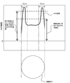
- FIG. 1 is a schematic diagram for explaining the average intensity of W when a line analysis is performed on the average intensity of W in the oxide catalyst particles.
- FIG. 1 shows an example in which Sw is measured and calculated. As shown in FIG. 1, when the average intensity of W existing in the whole oxide catalyst particle is higher than the average intensity of W existing in a region within 5 ⁇ m from the particle surface, and Sw exceeds 1.05, The effect by invention can be show
- the oxide catalyst in which W is unevenly distributed on the particle surface and in the vicinity thereof has high wear resistance because W having high hardness exists on the surface and in the vicinity thereof, and is particularly preferable for use in a fluidized bed reaction.
- W has a higher melting point than other components contained in the catalyst, and therefore has the effect of preventing the Mo-containing oxide having a low melting point from precipitating on the surface, particularly when the reaction temperature is high. Useful.
- W having a high melting point is unevenly distributed on and near the catalyst particle surface prevents the catalyst from adhering to each other due to the elution of components having a low melting point and the fluidity of the catalyst in the fluidized bed reaction from being deteriorated. It is thought that there is also.
- the surface is exposed most frequently to the contact frequency between particles and the reaction atmosphere (gas, temperature, pressure, etc.), so W is unevenly distributed in a relatively close area within 5 ⁇ m from the surface.
- the amount of W added to the oxide catalyst is small, the effect can be exhibited effectively, and adverse effects on performance such as decomposition of ammonia due to excessively added W can be reduced and added. Since the amount of W to be saved can be saved, it is economically preferable.
- Iw (average intensity of W in the diameter from the both ends (surface) of the longest particle diameter to the center from 5 ⁇ m) / (average intensity of W in the entire longest particle diameter)
- 0.3 ⁇ Iw ⁇ 1 is preferable, and 0.5 ⁇ Iw ⁇ 0.99 is more preferable.
- the method for producing an oxide catalyst of the present embodiment is a method for producing an oxide catalyst used in a gas phase catalytic oxidation reaction or gas phase catalytic ammoxidation reaction of propane or isobutane, I) A step of obtaining a raw material mixture containing a Mo compound, a V compound, a W compound, an Nb compound, and a compound of at least one element selected from the group consisting of Sb and Te at a specific atomic ratio. (Hereinafter referred to as “raw material preparation step”), (II) a step of drying the raw material preparation liquid to obtain a dry powder (hereinafter referred to as “drying step”), and (III) firing the dry powder. Process (hereinafter referred to as “firing process”).
- (I) Raw material preparation step In the raw material preparation step, preferably, a compound containing a constituent element of the oxide catalyst is dissolved or dispersed in a solvent and / or a dispersion medium to obtain a raw material preparation solution.
- a solvent and / or dispersion medium water can be usually used.
- the amount of the solvent and the dispersion medium in the raw material preparation liquid is a catalyst constituent element that sufficiently dissolves and / or disperses a compound containing the constituent element of the oxide catalyst (hereinafter also simply referred to as “catalyst constituent element”).
- the final raw material preparation liquid It is preferably 70 to 95% by mass and more preferably 75 to 90% by mass with respect to the total amount.
- a compound containing a constituent element of an oxide catalyst including a salt.
- the dissolution procedure, mixing procedure or dispersion procedure of the constituent element compound is not particularly limited.
- the raw materials such as constituent element compounds may be dissolved, mixed or dispersed in the same aqueous medium, or the raw materials such as constituent element compounds may be dissolved, mixed or dispersed in different aqueous media and then their aqueous The medium may be mixed. Moreover, you may heat and / or stir as needed.
- the blending ratio of each constituent element compound can be adjusted as appropriate in consideration of the ratio of each constituent element in the finally obtained oxide catalyst and the blending amount of each constituent element compound added in the subsequent step such as the firing step. Good.
- the raw material preparation liquid preferably contains Mo, V, Nb, and Te and / or Sb.
- a constituent element compound is not specifically limited, For example, the following compound is mentioned.
- Mo compound the Mo-containing compound (hereinafter referred to as “Mo compound”; the same applies to other elements) as a raw material of Mo include ammonium heptamolybdate [(NH 4 ) 6 Mo 7 O 24 ⁇ 4H 2.
- ammonium heptamolybdate (NH 4 ) 6 Mo 7 O 24 ⁇ 4H 2 O] is preferable.
- V compound as a raw material for V include ammonium metavanadate [NH 4 VO 3 ], vanadium pentoxide [V 2 O 5 ] and vanadium chloride [VCl 4 , VCl 3 ].
- ammonium metavanadate [NH 4 VO 3 ] is preferred.
- Nb compound used as a raw material for Nb include niobic acid, niobium inorganic acid salt, and niobium organic acid salt. Among these, solubility, Nb valence, versatility, and availability.
- Niobic acid is preferable from the viewpoint of the above. Niobic acid is represented by a chemical formula of Nb 2 O 5 .nH 2 O and is also referred to as niobium hydroxide or niobium oxide hydrate.
- the dicarboxylic acid / niobium molar ratio is preferably 1 to 4.
- an oxalic acid is preferable from a viewpoint of solubility and the appropriateness of complex formation with Nb.
- Sb compound used as the raw material for Sb examples include antimony oxides [Sb 2 O 3 , Sb 2 O 5 ], antimony acid [HSbO 2 ], antimonic acid [HSbO 3 ], and ammonium antimonate [(NH 4 ).
- diantimony trioxide [Sb 2 O 3 ] is preferable.
- Te compound that is a raw material of Te examples include telluric acid [H 6 TeO 6 ] and metal tellurium. Among these, viewpoints such as solubility, valence of Te, versatility, and availability. Therefore, telluric acid [H 6 TeO 6 ] is preferable.
- Examples of the W compound as a raw material for W include, for example, ammonium paratungstate, ammonium metatungstate, tungstic acid, tungsten trioxide, tungsten dioxide, silicotungstic acid, silicotungsto molybdic acid, caivanadotungstic acid, sodium tungstate, Examples include calcium tungstate, calcium tungstate, and cobalt tungstate. Among these, from the viewpoints of solubility, valence of W, versatility, availability, influence of coexisting metal elements, etc., trioxide Tungsten, ammonium metatungstate, and cobalt tungstate are preferred.
- Z compounds which are raw materials for Mn, B, Ti, Al, Ta, alkali metals, alkaline earth metals, La, Ce, Pr, Yb, Co, Y and Sc.
- the substance contains any of these elements, and examples thereof include compounds containing these elements, and metals obtained by solubilizing these elements with an appropriate reagent.
- the compounds containing these elements include ammonium salts, nitrates, carboxylates, ammonium carboxylates, peroxocarboxylates, ammonium peroxocarboxylates, ammonium halides, halides, acetylacetonates and alkoxides.
- water-soluble raw materials such as nitrate and carboxylate are preferable.
- the raw material preparation liquid preferably contains a silica raw material.
- Silica sol can be used as the silica raw material, and powder silica can also be used for a part or all of the silica raw material.
- the silica sol preferably contains 0 to 270 ppm by mass, more preferably 10 to 270 ppm by mass of nitrate ions with respect to the mass of SiO 2 (silica) therein.
- the term “silica sol” refers to an aqueous silicic acid solution in a transparent state.
- the nitrate ion concentration in the silica sol which is the raw material of the silica carrier, to the above specific range
- a silica sol as the carrier raw material
- the nitrate ion concentration relative to the silica in the silica sol can be determined by ion chromatography.
- the measurement apparatus and measurement conditions are shown below.
- an ion chromatograph (trade name “IC-2001”) manufactured by Tosoh Corporation can be used.
- TSKgel superIC-AZ is used as a column, and TSKguardcolumn superIC-AZ is used as a guard column. Further, TSKsuppress A is used as the suppressor valve cleaning liquid.
- a 1.9 mmol / L NaHCO 3 aqueous solution and a 3.2 mmol / L Na 2 CO 3 aqueous solution are mixed and used. The flow rate at that time is 0.8 mL / min.
- silica sol production method examples include (1) dialysis after neutralization of water glass, (2) electrodialysis, (3) dissolution of metal silicon in ammonia or amine aqueous solution, and (4) solution of silica gel.
- the most common method for producing silica sol is a method using water glass deNa removal with an ion exchange resin.
- LiOH, NaOH, KOH or the like is added as a stabilizer in order to enhance the stability under high concentration.
- the stable pH range of silica sol is about 8-10.
- the silica particles in the sol need to repel each other.
- a stabilizer is added to adsorb OH 2 ⁇ on the surface of the silica particles to exhibit a stabilizing effect due to negative charges, thereby preventing gelation.
- alkali alkali metal ions in the stabilizer
- the alkali ions are adsorbed and negative charge is reduced, resulting in instability.
- many silica sols that have the original characteristics of these silica sols and can be used for various purposes are commercially available.
- Snowtex series of Nissan Chemical Industries, Ltd. uses Snowtex 30 with a silica sol concentration of 30%, Snowtex C used for applications that may cause gelation, and volatile weak bases as stabilizers.
- Snowtex N for the purpose that there is no fear of residual alkali
- Snowtex O suitable for applications that require use in acidity, etc.
- the surface of the silica particles of the silica sol obtained by the above-mentioned production method it is classified into an acidic type and an alkaline type.
- any type there are almost no nitrate ions in the silica sol.
- hydrogen ions are mainly used as a stabilizer
- sodium ions or ammonium ions are used as a stabilizer.
- acidic type counter anion SO 4 2 ⁇ , Cl ⁇ and the like are used
- OH ⁇ is generally used.
- silica sol in which the mass ratio of nitrate ions is 0 to 270 ppm by mass relative to the mass of silica, water, which is a general method for producing silica sol, is used.
- nitrate such as nitric acid or ammonium nitrate to adjust the amount of nitrate ions to 0 to 270 mass ppm with respect to silica.
- anions and nitrate ions in the aqueous water glass solution may be exchanged by ion exchange.
- the nitrate ion amount may be adjusted by adding nitrate ions to an existing silica sol with a dropper or the like.
- the nitric acid source may be nitric acid or a salt such as ammonium nitrate.
- the raw material of the silica carrier may be only silica sol, but a part of it can be replaced with powder silica.
- powdered silica as a raw material for the silica support, effects such as improvement in catalyst activity and / or yield of the target product can be expected. Remarkably low.
- the term “powdered silica” refers to solid SiO 2 fine particles. If the primary particle diameter of silica is too large, the resulting catalyst tends to become brittle, and nanometer-sized powder silica is preferred.
- the powder silica is preferably produced by a high heat method from the viewpoint of the purity of the contained silica. Specific examples of preferable powdered silica include Aerosil 200 (trade name) manufactured by Nippon Aerosil Co., Ltd.
- the powder silica is preferably dispersed in water in advance.
- the method for dispersing the powder silica in water is not particularly limited, and the powder silica can be dispersed by using a general homogenizer, a homomixer, an ultrasonic vibrator, or the like alone or in combination.
- silica sol and powder silica are used in combination as raw materials for the silica carrier, it is preferable that 20 to 80 mass% of the total amount of silica sol and powder silica is powder silica.
- the proportion of the powdered silica is within this range, a catalyst having sufficient wear resistance and catalytic activity can be easily prepared as compared with other proportions.
- powdered silica need not contain nitrate ions. Even if the nitrate ion concentration in the silica sol is controlled to 10 to 270 mass ppm with respect to SiO 2 for the purpose of increasing the yield and / or physical strength of the target product, the nitrate ions contained in the powder silica There is no need to control.
- X compounds The solvent and / or dispersant and water, Mo compound, V compound, Nb compounds, Te and / or Sb compounds (hereinafter, referred to as. "X compounds") the case of preparing a raw material mixture containing and Z Compound Example Therefore, a raw material preparation process will be described.
- an Mo compound, a V compound, an X compound, and a Z compound are added to water and heated to prepare an aqueous mixture (A).
- the aqueous mixture (A) heating temperature and time of the preparation is such that each raw material is in a state capable of sufficiently dissolved and / or dispersed, from this viewpoint, the heating temperature is preferably 70 The heating time is preferably 30 minutes to 5 hours.
- the number of rotations of stirring at the time of heating can be adjusted to an appropriate number of rotations at which the raw materials are easily dissolved and / or dispersed.
- the raw material is a metal salt
- the inside of the container may be an air atmosphere, but from the viewpoint of adjusting the oxidation number of the resulting oxide catalyst, a nitrogen atmosphere can also be used.
- an amount of hydrogen peroxide suitable for the aqueous mixed solution (A) can be added as necessary.
- H 2 O 2 / Sb molar ratio
- the heating temperature and time after adding hydrogen peroxide to the aqueous mixed liquid (A) are preferably such that the liquid phase oxidation reaction with hydrogen peroxide can proceed sufficiently.
- the heating temperature is preferably 30 ° C. to 70 ° C., and the heating time is preferably 5 minutes to 4 hours.
- the number of rotations of stirring during heating can be adjusted to an appropriate number of rotations in which a liquid phase oxidation reaction with hydrogen peroxide easily proceeds. From the viewpoint of sufficiently proceeding with the liquid phase oxidation reaction with hydrogen peroxide, it is desirable to maintain a stirring state during heating.
- the Nb compound and dicarboxylic acid are added to another water, and heated and stirred to prepare a mixed solution (B 0 ).
- the dicarboxylic acid include oxalic acid [(COOH) 2 ].
- H 2 O 2 / Nb (molar ratio) forms a complex with the Nb compound and stabilizes it in a dissolved state, appropriately adjusts the redox state of the catalyst constituent elements, and makes the catalyst performance of the resulting catalyst appropriate.
- it is preferably 0.5 to 20, and more preferably 1 to 10.
- the aqueous mixed liquid (A) and the aqueous mixed liquid (C) are mixed at a suitable blending ratio to obtain the aqueous mixed liquid (D).
- the obtained aqueous mixed solution (D) is aged as necessary to obtain a slurry of the raw material preparation solution.
- the aging of the aqueous mixed liquid (D) means that the aqueous mixed liquid (D) is allowed to stand for a predetermined time or is stirred.
- the aging time includes not only the aging time before spray drying but also the time from the start to the end of spray drying.
- the aging time is preferably 90 minutes or longer and 50 hours or shorter, and more preferably 90 minutes or longer and 6 hours or shorter from the viewpoint of improving the catalyst performance of the resulting composite oxide.
- the aging time is less than 90 minutes or exceeds 50 hours, the aqueous mixed liquid (IV) having a suitable redox state (potential) is hardly formed, and the catalytic performance of the resulting composite oxide tends to be reduced.
- the processing speed of the spray dryer is usually limited, and after a part of the aqueous mixture (IV) is spray-dried, all the mixture is spray-dried. It takes time to finish. In the meantime, the aging of the aqueous mixture not spray-dried is continued. Therefore, the aging time includes not only the aging time before drying in step (c) described later but also the time from the start to the end of drying.
- the aging temperature is preferably 25 ° C. or higher from the viewpoint of preventing condensation of the Mo component and precipitation of V.
- the aging temperature is preferably 25 ° C. or more and 65 ° C. or less, and more preferably 30 ° C. or more and 60 ° C. or less.
- the atmosphere around the aqueous mixture (D) at the time of aging for example, the atmosphere in the vessel when aging the aqueous mixture (D) in the vessel preferably has a sufficient oxygen concentration.
- the gas phase oxygen concentration in the surrounding atmosphere is more preferably 1% by volume or more, for example, aging in an air atmosphere is preferable.
- the gas phase oxygen concentration can be measured by a general method, for example, using a zirconia oxygen analyzer.
- the place where the gas phase oxygen concentration is measured is preferably near the interface between the aqueous mixed liquid (D) and the gas phase from the viewpoint of grasping the accurate oxygen concentration.
- the gas phase oxygen concentration it is preferable to measure the gas phase oxygen concentration at the same point three times within 1 minute, and use the arithmetic average value of the measurement results of the three times as the gas phase oxygen concentration.
- the dilution gas for reducing the gas phase oxygen concentration is not particularly limited, and examples thereof include nitrogen, helium, argon, carbon dioxide, and water vapor. Industrially, nitrogen gas is preferable. Further, as the gas used for increasing the gas phase oxygen concentration, for example, pure oxygen or air with a high oxygen concentration is preferable.
- the redox potential of the aqueous mixture (D) is dominated by the potential of the aqueous mixture (C) (for example, 600 mV / AgCl when the dicarboxylic acid in the aqueous mixture (C) is oxalic acid). It is considered that the potential decreases with time when the peroxide of dicarboxylic acid and Nb contained in the aqueous mixed liquid (C) and other metal components cause some kind of oxidation-reduction reaction.
- a preferable redox potential of the aqueous mixture (D) is 450 to 530 mV / AgCl, and more preferably 470 to 510 mV / AgCl.
- the oxygen concentration in the atmosphere around the aging aqueous mixed solution (D) is preferably 1% by volume or more.
- the oxygen concentration in the atmosphere around the aging aqueous mixture (D) is preferably 25% by volume or less. In any case, since oxygen in the gas phase affects the redox state of the slurry, it is necessary to maintain the oxygen concentration within an appropriate range. The range is more preferably 5 to 23% by volume, still more preferably 10 to 20% by volume.
- aqueous mixture (D) may occur.
- concentration of the aqueous mixture (D) may occur.
- aging is preferably performed in an atmosphere having an oxygen concentration of 1 to 25% by volume.
- the liquid density, the amount of the raw material mixture, the number of revolutions of the stirring blade, etc. can be controlled. preferable.
- the power (hereinafter referred to as “Pv”) applied from the stirring blade of the stirring device to the raw material mixed solution per unit volume in the device for obtaining the raw material mixed solution is calculated by the following formula (formula A).
- Pv is preferably 0.005 ⁇ 300kW / m 3, more preferably 0.01 ⁇ 280kW / m 3, more preferably from 0.1 ⁇ 250kW / m 3.
- Np the power number which is a dimensionless number related to the power required for stirring
- ⁇ the liquid density (kg / m 3 )
- n the rotational speed (s ⁇ 1 ) of the stirring blade
- d Indicates a stirring blade diameter (m)
- V indicates a raw material preparation liquid amount (m 3 ).
- Np can be calculated using the following formula (formula B1).
- b represents the width (m) of the stirring blade
- d represents the stirring blade diameter (m)
- D represents the stirring tank diameter (m)
- Z represents the liquid depth (m)
- ⁇ represents the stirring blade Indicates the inclination angle (°) of the wing from the horizontal.
- the viscosity at room temperature (25 ° C.) of the obtained raw material preparation liquid is that the raw material preparation liquid is gelled, it becomes difficult to obtain a dry powder by closing the inside of the pipe, and the catalyst performance is lowered.
- the formation of dents in the catalyst particles after spray drying, or the suppression of the catalyst particles from becoming a distorted particle shape preferably 1 to 100 cp, more preferably 2 to 90 cp, Preferably, it is 2.5 to 80 cp.
- the viscosity of the raw material preparation liquid can be measured by, for example, a method of measuring using a commercially available viscometer, or a method of measuring a pressure loss in a pipe through which the raw material preparation liquid flows.
- a method of measuring a pressure loss in a pipe through which the raw material preparation liquid flows For example, when measuring the viscosity of a liquid that gradually gelates without stirring, the viscosity may change gradually when measured using a commercially available viscometer. From the viewpoint, it is preferable to measure the viscosity by a method of measuring the pressure loss in the pipe through which the raw material mixture is circulated.
- ⁇ P represents the pressure loss (mmH 2 O) in the pipe
- ⁇ represents the liquid viscosity (cp) at the measurement temperature
- u represents the liquid flow average speed (m / s)
- L represents the pipe length.
- M and D indicates the pipe diameter (m).
- the raw material preparation liquid is obtained by mixing a plurality of raw material liquids in which the respective components are dissolved
- stirring may be stopped after substantially all the solid particles in each raw material liquid are dissolved.
- the oxide catalyst is a silica-supported product
- the compound containing the catalyst constituent element is sufficiently dissolved and / or dispersed, the redox state of the catalyst constituent element is adjusted appropriately, and the resulting catalyst particle shape and / or strength is preferred.
- the raw material preparation liquid is prepared so as to contain silica sol.
- Silica sol can be added as appropriate.
- a part of the silica sol can be made into an aqueous dispersion of powdered silica.
- An aqueous dispersion of powdered silica can also be added as appropriate.
- the above raw material preparation steps can be repeatedly performed according to the production amount.
- W is contained in the raw material preparation liquid obtained through the raw material preparation step (I) and the dry powder obtained through the drying step (II) described later in the method for producing an oxide catalyst, the above formula (1 ), B> 0.
- W exists also in the area
- a dry powder (dried product) is obtained by drying the slurry of the raw material preparation liquid obtained through the raw material preparation process. Drying can be performed by a known method, for example, spray drying or evaporation to dryness.
- a fine spherical dry powder or a catalyst precursor is used from the viewpoint of making fluidity in a reactor in a preferable state. Since it is preferable to obtain, it is preferable to employ spray drying.
- the atomization in the spray drying method may be any of a centrifugal method, a two-fluid nozzle method, or a high-pressure nozzle method.
- the drying heat source air heated by steam, an electric heater or the like can be used.
- the inlet temperature of the dryer of the spray dryer is preferably 150 to 300 ° C. from the viewpoints of obtaining a favorable shape and / or strength of the obtained catalyst particles and improving the catalyst performance of the obtained composite oxide.
- the outlet temperature of the dryer is preferably 100 to 160 ° C.
- the spraying speed, the feeding speed of the slurry, the rotation speed of the atomizer in the case of the centrifugal method, etc. may be adjusted according to the size of the apparatus so that the particle diameter of the obtained dry powder falls within a suitable range.
- the average particle size of the dry powder is preferably 5 ⁇ m to 200 ⁇ m, more preferably 10 to 150 ⁇ m.
- the average particle size of the dry powder particles is obtained by measuring the particle size distribution in accordance with JIS R 1629-1997 “Method for measuring particle size distribution of fine ceramic raw material by laser diffraction / scattering method” and averaging on a volume basis. It is a thing. More specifically, a part of the dry powder is calcined in air at 400 ° C. for 1 hour, and the obtained particles are measured using a laser diffraction scattering method particle size distribution measuring apparatus BECKMAN COULTER LS230. The average particle size is measured after a part of the dry powder is “baked at 400 ° C. in air for 1 hour” in order to prevent the dry powder from being dissolved in water. In other words, “baking in air at 400 ° C.
- the average particle size is measured as follows according to a manual attached to a laser diffraction / scattering particle size distribution measuring apparatus (manufactured by BECKMAN COULTER, trade name “LS230”). First, after background measurement (RunSpeed 60), 0.2 g of particles are weighed into a screw tube of an appropriate size, and 10 cc of water is added. The screw tube is covered (sealed) and shaken well to disperse the particles in water. An ultrasonic wave of 300 W is applied by the apparatus, and the screw tube is sufficiently shaken again.
- the particles dispersed in water are injected into the apparatus main body using a dropper so as to have an appropriate concentration (concentration 10, PIDS60).
- concentration 10, PIDS60 concentration 10, PIDS60.
- concentration display is stable, the application of ultrasonic waves is stopped, and after standing for 10 seconds, the measurement is started (measurement time 90 seconds).
- the median diameter value of the measurement result is defined as the average particle diameter.
- the performance of the oxide catalyst finally obtained from the absorption or reflection spectrum can be predicted.
- the oxidation / reduction degree of the oxide catalyst is changed by heating during the drying process, and the performance of the oxide catalyst is affected by the change.
- a part of the dry powder adheres to and / or deposits on the wall surface and / or bottom of the device and stays in the device for a long time. As a result, unintended heat is applied to the dry powder, and the redox degree changes.
- the oxidation-reduction degree of the dry powder hardly affects the performance of the obtained catalyst.
- the redox degree of the dry powder tends to affect the performance of the oxide catalyst.
- the preparation method is optimized in consideration of the oxidation-reduction degree of the oxide catalyst, if the oxidation-reduction degree of the dry powder is out of the desired range, the catalyst performance tends to deteriorate as a matter of course.
- the color of the dry powder changes as the redox degree changes.
- the performance of the oxide catalyst tends to deteriorate, particularly as the dry powder turns black. This is because, for example, the organic component or inorganic component contained in the dry powder is thermally decomposed by unintentional heating, whereby the surrounding metal element is reduced, or a redox reaction between the metal elements occurs. Can be considered. Therefore, the performance of the oxide catalyst can be predicted by measuring the degree of discoloration by measuring the absorption or reflection spectrum of the dry powder.
- a dry powder accumulation preventing apparatus such as a vibrator that gives vibration to the spray drying apparatus or an air knocker that gives an impact. preferable. It is also preferable that spray drying is temporarily stopped at an appropriate frequency and the inside of the apparatus is washed with water or the like. The measurement of the spectrum is preferably performed immediately after the drying process in which unintended heating is likely to occur.
- the operating conditions of the air knocker installed in the drying device can be arbitrarily adjusted according to the size of the device, the wall thickness, or the degree of peeling of the deposits.
- Examples of operating conditions include air knocker impact strength, impact frequency, increase / decrease in the number of air knockers installed, and change of installation position.
- the impact strength of the air knocker is preferably so strong that the wall surface and / or other drying device parts are not deformed or broken even during long-term operation.
- the hitting frequency is preferably once or more per minute, and more preferably once or more per 10 seconds.
- the number and position of air knockers installed increase the number of parts where severe adhesion is observed by internal observation after long-term operation, or move the knocker of the part with little adhesion to the part with strong adhesion. Etc. are preferred.
- the method for measuring the absorption or reflection spectrum is not particularly limited, and can be determined, for example, by the absorbance of the dry powder measured using a visible / ultraviolet spectrophotometer.
- the dry powder that gives an oxide catalyst that is discolored black and has poor performance has an absorbance at a wavelength of 500 nm or more larger than that of the dry powder that is not discolored black. It was. Therefore, the absorbance at an arbitrary wavelength in the wavelength range of 500 nm or more, preferably 500 nm or more and 800 nm or less can be selected and used as an index of measurement.
- continuously measuring means measuring at a frequency of once or more every three months. More preferably, the spectrum is measured once a month, more preferably once a week, and particularly preferably once a day or more. The more frequently it is measured, the lower the risk of producing a large amount of dry powder with an inappropriate redox degree, but the absorption or reflection spectrum of the dry powder is less likely to change depending on the production conditions. Since it may be unnecessary, the frequency may be set as appropriate.
- step (i) may be determined.
- Step (i) the performance of the oxide catalyst finally obtained from the measured absorption or reflection spectrum is predicted, and the operating conditions in each step are controlled based on the predicted performance of the oxide catalyst, thereby improving the performance. It is possible to efficiently obtain an excellent catalyst.
- the absorption or reflection spectrum of the dry powder obtained under different drying conditions and the oxidation obtained from the dry powder. Correlation diagrams of product catalyst performance can be used.
- the absorption or reflection spectrum of the dry powder obtained under different drying conditions it is preferable to use the absorbance for a specific wavelength obtained using an ultraviolet-visible spectrophotometer from the viewpoint of obtaining a good correlation.
- the dry powder obtained under different drying conditions may change at least one of the supply amount per unit time of the raw material preparation liquid (aqueous raw material), the supply air amount per unit time and the supply air temperature in the drying process.
- the dry powder can be obtained by changing the operating conditions of the dry powder deposition preventing device attached to the drying device.
- the dry powder can be obtained by changing the number of revolutions of the disc and the disc diameter. Further, it may be a dry powder obtained by subjecting a dry powder obtained through the drying step to color change by heating at a different time and / or temperature.
- the absorption or reflection spectrum of the dry powder obtained under different drying conditions can be measured in the same manner as described above.
- each of the dry powders obtained under different drying conditions is further subjected to gas phase catalytic oxidation or gas phase catalytic ammoxidation reaction of propane or isobutane using an oxide catalyst obtained by calcining under the same conditions, The catalyst performance at that time is examined.
- the catalyst performance to be investigated include yield, activity, conversion, and yield of by-products, and these may be combined.
- an oxide catalyst with better performance can be easily obtained by changing the operating conditions in each step according to the expected value of the performance of the oxide catalyst finally obtained.
- step (i) depending on the monitored absorption or reflection spectrum, the operating conditions in at least one of the above-mentioned (I) raw material preparation step, (II) drying step, and (III) firing step described later To decide. From the viewpoint of ease of control, it is preferable to determine the operating conditions in the (II) drying step according to the absorption or reflection spectrum.
- steps for determining the operation conditions step (i-1), step (i-2)
- Step (i-1) is a step of determining the preparation conditions in the raw material preparation step according to the measured absorption or reflection spectrum.
- the correlation between the absorption or reflection spectra of the dry powder obtained under different dry conditions and the performance of the oxide catalyst obtained from the dry powder is used to determine the final oxide catalyst.
- the preparation conditions are determined so that the performance is good.
- the means for “determining the preparation conditions” in this step is not particularly limited.
- the constituent element compound when dissolved and / or dispersed in an aqueous medium, the oxidation / reduction of the catalyst components according to the dissolution procedure or the mixing procedure. Examples thereof include a method for controlling the degree, a method for adding an oxidizing agent or a reducing agent, and the like.
- Step (i-2) is a step of determining the drying conditions in the drying step according to the measured absorption or reflection spectrum.
- the correlation between the absorption or reflection spectra of the dry powder obtained under different dry conditions and the performance of the oxide catalyst obtained from the dry powder is used to determine the final oxide catalyst.
- the drying conditions are determined so that the performance is good.
- the supply amount of the raw material preparation liquid per unit time, the supply air amount, the supply air temperature per unit time examples thereof include a method of changing operating conditions of a dry powder accumulation preventing device attached to the drying device. From the viewpoint of maintaining the performance, physical shape, strength, etc. of the obtained catalyst, a method of changing the operating conditions of the dry powder deposition preventing apparatus is more preferable.
- the atomization is a centrifugal method, the number of revolutions of the disc and the disc diameter may be changed. Moreover, you may combine these.
- the dry powder has a content of particles having a particle diameter of 25 ⁇ m or less of 20% by mass or less, preferably 15% by mass or less, more preferably 10% by mass or less, still more preferably 5% by mass or less, and particularly preferably 2% by mass or less.
- the catalyst precursor particles are likely to be fixed. Therefore, it is estimated that there is a possibility that heat transfer to the inside may be insufficient due to the lamination of the fixed matter on the wall surface of the calciner, or that an excessively calcined catalyst stuck for a long time may be mixed.
- the “catalyst precursor” refers to a compound that is generated in the middle of the firing step described later. For example, what is obtained by pre-stage calcination is called a catalyst precursor.
- the oxide catalyst contains Mo, Sb, Te or the like
- a low melting point compound is likely to be generated during the firing. Since particles having a particle size of 25 ⁇ m or less have a larger surface ratio than particles having a particle size of more than 25 ⁇ m, it is considered that fixation is more likely to occur. If the amount of fixing becomes too large, problems such as inability to obtain a sufficient firing temperature for the catalyst layer and inability to secure the production amount occur. Therefore, it is preferable that the number of particles having a particle size of 25 ⁇ m or less is small before firing, that is, the content of the particles is 20% by mass or less.
- the dry powder preferably has an average particle size of 5 to 200 ⁇ m, more preferably 10 to 150 ⁇ m, still more preferably 35 to 70 ⁇ m, still more preferably 40 to 65 ⁇ m, still more preferably 42 to 65 ⁇ m, and particularly preferably. It is prepared to be 45 to 63 ⁇ m, very preferably 45 to 60 ⁇ m.
- the average particle size is 5 ⁇ m or more, it is possible to suppress decrease in fluidity and decrease in yield of the target product in the fluidized bed reaction, or scattering from the fluidized bed reactor increases the amount of catalyst. It tends to be able to prevent.
- the average particle size is 200 ⁇ m or less, the fluidity of the oxide catalyst is lowered, and the contact efficiency with the reaction gas is lowered, whereby the yield of the target product in the fluidized bed reaction tends to be suppressed. .
- the catalyst precursor in the calcining step is adjusted by adjusting the average particle size of the dry powder to preferably 35 to 70 ⁇ m and the content of particles having a particle size of 25 ⁇ m or less to 20% by mass or less.
- the reduction rate of the body can be adjusted to a preferred range.
- the dry powder usually contains at least one of ammonium root, organic acid and inorganic acid.
- the ammonium root evaporates to ammonia gas, which reduces the dry powder or catalyst precursor particles from the gas phase.
- the reduction rate varies depending on the firing time and firing temperature in the pre-stage firing described below.
- the firing time is long or when the firing temperature is high, the reduction easily proceeds and the reduction rate becomes high.
- a large amount of dry powder having a relatively small particle size typically, the average particle size is less than 35 ⁇ m or the content of particles having a particle size of 25 ⁇ m or less. If it exceeds 20% by mass, the particles of the dry powder or catalyst precursor are entrained in the inert gas or fluctuate with the rotation of the calcining tube that is the calciner, and there are many small particles that go back in the calcining tube.
- the reason why the content of particles having a particle diameter of 25 ⁇ m or less is measured after “baking in air at 400 ° C. for 1 hour” is to prevent the dry powder from being dissolved in water. That is, “calcination in air at 400 ° C. for 1 hour” is exclusively for measurement, and is not related to the later-described firing step. It may be considered that the particle diameter does not substantially change before and after the firing. Although the reduction rate of the sample obtained by this firing may be different from other dry powders, usually the sample is very small, so even if it is subjected to the firing step described later, it does not serve However, the performance of the entire catalyst is hardly affected.
- the measurement target of the average particle size is not necessarily a dry powder, and the average particle size of the calcined catalyst precursor may be measured as necessary.
- the content of particles having a particle size of 25 ⁇ m or less is 35 to 70 ⁇ m.
- Examples thereof include a method of adjusting the supply amount of the mixed liquid and a method of classifying the dry powder.
- the classification method is not particularly limited, and for example, a method using a general apparatus such as a centrifugal classifier, an air classifier, a gravity classifier, an inertia classifier, a sieve, and a cyclone can be employed.
- a dry classifier can be suitably used from the viewpoint of preventing elution of the catalyst constituent elements into the solvent and not adversely affecting the catalyst performance.
- the apparatus is adjusted to a condition such that the recovery rate of the dry powder in the classification is preferably 75% by mass or more, more preferably 80% by mass or more, or an apparatus that satisfies the conditions. It is preferable to select and use.
- the calcination step is performed by coexisting a solid of a compound containing W (hereinafter referred to as “W-containing compound solid”) in the dry powder obtained through the drying step.
- W-containing compound solid a solid of a compound containing W
- the (III) firing step is a step of obtaining the fired powder by calcination in the presence of a W-containing compound solid in the pre-fired powder obtained by firing the dry powder (hereinafter referred to as (b-2) ) (Also referred to as a process).
- the (III) firing step may optionally include a step (hereinafter also referred to as (b-3) step) in which the fired powder and the W-containing compound solid coexist. .
- a step hereinafter also referred to as (b-3) step
- an oxide catalyst is obtained. That is, in the firing step, as described later, conditions such as temperature may be changed at each stage, and firing may be performed in multiple stages, or may be performed in one stage with constant conditions.
- the timing at which the W-containing compound solid is allowed to coexist can be appropriately selected.
- the setting of the firing conditions and the setting of the timing for coexisting the W-containing compound solid may be independent from each other, and are selected independently from the viewpoint of the desired performance of the oxide catalyst, the simplicity of the manufacturing process, etc. be able to.
- a rotary furnace (rotary kiln) can be used, for example.
- the shape of the calciner is not particularly limited, but a tubular shape (firing tube) is preferable from the viewpoint of continuous firing, and a cylindrical shape is particularly preferable.
- the heating method is preferably an external heating type from the viewpoint of easy adjustment of the firing temperature so as to have a preferable temperature rise pattern, and an electric furnace can be suitably used.
- the size and material of the firing tube an appropriate one can be selected according to the firing conditions and the production amount.
- the inner diameter of the calcining tube is preferably 70 to 2000 mm, more preferably 100 to 1700 mm, from the viewpoints of preventing unevenness in the calcining temperature distribution in the catalyst layer and adjusting the calcining time and production amount to appropriate values. It is.
- the length of the calcining tube is such that the residence time of the dry powder and catalyst precursor particles in the calcining tube, that is, the distribution of the calcining time, is minimized, the distortion of the calcining tube is prevented, the calcining time and the production amount are appropriate. From the viewpoint of adjusting the value, etc., the thickness is preferably 200 to 10,000 mm, more preferably 800 to 8000 mm.
- the thickness is preferably 2 mm or more, more preferably 4 mm or more, from the viewpoint of having a sufficient thickness that does not damage the fired tube. Further, from the viewpoint that the impact is sufficiently transmitted to the inside of the firing tube, the thickness is preferably 100 mm or less, more preferably 50 mm or less.
- the firing tube is in the direction in which the powder flows. It is preferable that the height of the outlet is lower than the height of the powder inlet.
- the inclination angle ⁇ from the horizontal is preferably 0 ° ⁇ ⁇ 80 °, and more preferably 1 ° ⁇ ⁇ ⁇ 40 °.
- the material of the calciner is not particularly limited as long as it is preferably heat-resistant and has a strength that does not break due to impact.
- SUS can be suitably used.
- the calcining tube It is also possible to divide the calcining tube into two or more areas by providing a weir plate in the calcining tube that has a hole in the center for passage of the powder perpendicular to (or substantially perpendicular to) the powder flow. .
- a weir plate By installing the weir plate, it becomes easy to secure the residence time of the powder in the firing tube.
- the number of weir plates may be one or more.
- the material of the barrier plate is preferably a metal, and the same material as that of the firing tube can be suitably used.
- the height of the weir plate can be adjusted according to the residence time to be secured.
- the height of the weir plate is preferably 5 to 50 mm, more preferably 10 to 40 mm. More preferably, it is 13 to 35 mm.
- the thickness of the weir plate is not particularly limited and is preferably adjusted according to the size of the firing tube.
- the thickness of the barrier plate is preferably 0.3 mm or more and 30 mm or less, more preferably 0.5 mm or more and 15 mm or less.
- the rotation speed of the firing tube is preferably 0.1 to 30 rpm, more preferably 0.5 to 20 rpm, and still more preferably 1 to 10 rpm.
- the temperature of the dry powder is increased from a temperature lower than 400 ° C. from the viewpoint of bringing the obtained catalyst into a preferable redox state, improving the catalyst performance, and the like. It is preferable to raise the temperature continuously or stepwise to a temperature in the range of 800 ° C.
- the calcination atmosphere may be an air atmosphere or an air flow, but from the viewpoint of easy adjustment of the catalyst to a preferred redox state, at least a part of the calcination is an inert gas substantially free of oxygen such as nitrogen. It is preferable to carry out while distributing.
- the supply amount of the inert gas is preferably 50 N liter / hr or more, more preferably 50 to 5000 N liter / hr, per 1 kg of the dry powder. More preferably, it is 50 to 3000 N liter / hr.
- N liter means a liter measured at standard temperature and pressure conditions, that is, at 0 ° C. and 1 atm.
- the supply amount of the inert gas is preferably 50 Nl / hr or more, more preferably 50 to 5000 Nl / hr, per 1 kg of the dry powder from the viewpoint of adjusting to a preferable redox state. More preferably, it is 50 to 3000 N liter / hr.
- the contact form between the inert gas and the dry powder may be a countercurrent contact or a cocurrent contact. However, considering the gas components generated from the dry powder and the air that can be mixed in a trace amount in the dry powder, Flow contact is preferred.
- the dry powder is preferably fired while circulating an inert gas substantially free of oxygen such as nitrogen.
- the dry powder usually may contain ammonium root, organic acid, inorganic acid, etc. in addition to moisture.
- the reduction rate of the oxide catalyst should be within the desired range, since only the reduction needs to be performed in the calcination step. is there.
- an oxidizing component or a reducing component may be added to the firing atmosphere so that the reduction rate falls within a desired range. Calcination is preferably carried out so that the resulting oxide catalyst has a reduction rate of 8 to 12% and a specific surface area of 5 to 30 m 2 / g.
- the specific surface area of the catalyst is 5 to 30 m 2 / g, more sufficient activity is obtained, deterioration is further suppressed, and the yield is further increased.
- the effect of addition of the molybdenum compound for maintaining the yield during the oxidation reaction or ammoxidation reaction the effect is more fully exhibited and does not show sharp deterioration. Can be reduced.
- the specific surface area is smaller than 5 m 2 / g, the active surface of the active species that controls the reaction is also small, and the effect of adding the molybdenum compound is difficult to be exhibited.
- Reduction rate (%) ((n 0 ⁇ n) / n 0 ) ⁇ 100 (6)
- n is the number of oxygen atoms satisfying the valence of the constituent element other than oxygen in the oxide catalyst or catalyst precursor
- n 0 is the constituent element other than oxygen in the oxide catalyst or catalyst precursor. Is the number of oxygen atoms required when each has the highest oxidation number.
- the value of (n 0 -n) in the above formula (6) can be obtained by oxidation-reduction titration of the sample with KMnO 4 .
- the value of (n 0 -n) can be determined by oxidation-reduction titration for both the catalyst precursor before the end of firing and the oxide catalyst after the end of firing.
- the measurement conditions are different between the catalyst precursor before the completion of the calcination and the catalyst after the calcination. An example of a measurement method is shown below for each of the catalyst precursor before the calcination and the catalyst after the calcination.
- the reduction rate is measured as follows. First, about 200 mg of a sample is accurately weighed in a beaker. An excessive amount of KMnO 4 aqueous solution having a known concentration is added thereto. Next, 150 mL of pure water at 70 ° C. and 2 mL of 1: 1 sulfuric acid (that is, a sulfuric acid aqueous solution obtained by mixing concentrated sulfuric acid and water at a volume ratio of 1/1) were added to the beaker, and then the opening of the beaker Is closed with a watch glass, and the liquid in the beaker is stirred in a 70 ° C. ⁇ 2 ° C. water bath for 1 hour to oxidize the sample.
- 1: 1 sulfuric acid that is, a sulfuric acid aqueous solution obtained by mixing concentrated sulfuric acid and water at a volume ratio of 1/1
- titration is performed with a KMnO 4 aqueous solution having a known concentration.
- the end point is the point where the liquid color becomes faint light pink by titration with KMnO 4 and continues for about 30 seconds.
- the amount of KMnO 4 consumed for the oxidation of the sample is determined. From this KMnO 4 amount, (n 0 -n) is calculated, and the reduction rate is obtained based on this.
- a reduction rate is measured as follows, for example. First, in a beaker, about 200 mg of the catalyst crushed in a mortar made of agate is precisely weighed. Thereto is added 150 mL of 95 ° C. pure water and 4 mL of 1: 1 sulfuric acid (that is, an aqueous sulfuric acid solution obtained by mixing concentrated sulfuric acid and water at a volume ratio of 1/1). Next, the mixture is stirred while maintaining the liquid temperature at 95 ° C. ⁇ 2 ° C., and titrated with an aqueous KMnO 4 solution having a known concentration.
- both the catalyst precursor before the end of calcination and the oxide catalyst after the end of calcination can be measured as follows.
- the sample is completely oxidized with oxygen by heating the sample to a temperature higher than the firing temperature at which the catalyst precursor or catalyst was calcined under conditions that prevent the constituent elements of the sample from volatilizing and escaping and in an oxygen-containing atmosphere. Then, an increased mass (amount of bound oxygen) is obtained, and a value of (n 0 -n) is obtained from this, and a reduction rate is obtained based on this.
- the dry powder is fired.
- the heating temperature of the dry powder starts from a temperature lower than 400 ° C., and is 550 to 700 ° C.
- Calcination is performed under calcination conditions where the temperature is raised continuously or stepwise to a temperature within the range, and calcination so that the reduction rate of the catalyst precursor during calcination is 8 to 12% when the heating temperature reaches 400 ° C. It is preferable to adjust the conditions.
- the amount of organic components such as oxalic acid contained in the dry powder, the amount of ammonium root derived from the raw material ammonium salt, the rate of temperature rise at the start of firing In the case of firing in an inert gas atmosphere, the amount of the inert gas is affected. In the case of firing in an air atmosphere, the temperature and time are affected. In order to reduce the reduction rate of the oxide catalyst to 8 to 12%, for example, at the time of calcination, the temperature rise is started from a temperature lower than 400 ° C. to decompose oxalate root, ammonium root, etc. in the dry powder. And a method in which the reduction of the catalyst precursor during the calcination when the heating temperature reaches 400 ° C. is made 8 to 12% when gas generation is almost finished.
- the specific surface area of the catalyst is affected by the temperature and time at which the catalyst is finally fired (heated) and the amount of the carrier supported when the catalyst is supported on a carrier such as silica, but when the heating temperature reaches 400 ° C.
- the reduction rate and final calcination temperature are particularly greatly affected.
- the final firing temperature is preferably 550 ° C. to 700 ° C.
- the firing time at that temperature is preferably 0.5 hours to 20 hours.
- the specific surface area tends to be smaller as the final firing temperature is higher and the firing time is longer.
- the reduction rate when the heating temperature reaches 400 ° C. is in the range of 8 to 12%, the specific surface area of the catalyst tends to be prevented from becoming excessively small or large.
- the reduction rate when the heating temperature reaches 400 ° C. is set within the range of 8 to 12%, and the final calcination temperature is set to 550. It is preferable that the temperature is in the range of 0 to 700 ° C.
- Calcination may be carried out in one step with constant conditions, but in order to efficiently obtain an oxide catalyst having a reduction rate of 8 to 12% and a specific surface area of 5 to 30 m 2 / g, It is preferable that the calcination includes pre-stage calcination and main calcination performed thereafter.
- the firing temperature in the pre-stage firing is preferably lower than the firing temperature in the main firing. More specifically, the pre-stage firing is performed in a temperature range of 250 to 400 ° C., and the main firing is performed at 550 to 700 ° C. It is preferable to carry out in the temperature range.
- a pre-baked powder is obtained by the pre-baking, and a main-baked powder is obtained by the main baking.
- the main calcination may be performed continuously after the pre-stage calcination, that is, by directly changing the calcination temperature in the pre-stage calcination from the calcination temperature in the main calcination, or once after the pre-stage calcination is completed, that is, in the pre-stage calcination.
- the temperature may be lowered once from the temperature and then heated to the firing temperature in the main firing.
- each of the pre-stage firing and the main firing may be divided into a plurality of firing stages having different firing conditions.
- the sample When measuring the reduction rate of the catalyst precursor during calcination, the sample may be taken out from the calcination apparatus at that temperature, but at a high temperature, it may be oxidized by contact with air and the reduction rate may change. Therefore, the sample taken out from the baking apparatus after cooling to room temperature may be used as the representative sample.
- a method for controlling the reduction rate when the heating temperature reaches 400 ° C. to a desired range specifically, a method for adjusting the firing temperature in the pre-stage firing, an oxidizing component such as oxygen in the atmosphere during firing And a method of adding a reducing component to the atmosphere during firing. Moreover, you may combine 2 or more types of methods among these.
- pre-stage calcination temperature The method of changing the calcination temperature in the pre-stage calcination is to adjust the reduction rate of the catalyst precursor when the heating temperature reaches 400 ° C. by changing the pre-stage calcination temperature. It is a technique to do. Usually, the reduction rate decreases when the pre-stage calcination temperature is lowered, and the reduction rate tends to increase when the pre-stage calcination temperature is raised. Therefore, the reduction rate can be controlled by changing the pre-stage calcination temperature.
- the method of adding an oxidizing component such as oxygen to the atmosphere at the time of firing is a method that can be used when reducing the reduction rate of the catalyst precursor when the heating temperature reaches 400 ° C.
- “during firing” may be pre-stage firing, main firing, or both firing.
- the oxidizing component added to the atmosphere during firing is the oxidizing component in the inert gas supplied to the firing apparatus, and the amount of the oxidizing component added depends on the concentration in the inert gas supplied to the firing apparatus. Can manage.
- the reduction rate of the catalyst precursor when the heating temperature reaches 400 ° C. can be controlled.
- the oxidizing component is oxygen
- air or an inert gas containing air
- oxygen in the air can be used as the oxidizing component.
- the method of adding a reducing component to the atmosphere during firing is a method that can be used to increase the reduction rate of the catalyst precursor when the heating temperature reaches 400 ° C.
- “during firing” may be pre-stage firing, main firing, or both firing.
- the reducing component added to the atmosphere during firing is the reducing component in the inert gas supplied to the firing device, and the amount of the reducing component added depends on the concentration in the inert gas supplied to the firing device. Can manage.
- the reduction rate of the catalyst precursor when the heating temperature reaches 400 ° C. can be controlled.
- the reducing component for example, ammonia can be used.
- the difference between the actual reduction rate and the desired reduction rate causes the necessary oxidizing component or reducing component to be reduced.
- the total amount can be calculated and added to the atmosphere during firing.
- a method for performing the firing atmosphere in an inert gas or a preferable oxidizing / reducing atmosphere is not particularly limited, but a firing apparatus having an appropriate seal structure and capable of sufficiently blocking contact with the outside air should be used. preferable.
- the pre-stage calcination is preferably performed under an inert gas flow, preferably the pre-stage calcination temperature is 250 ° C. to 400 ° C., more preferably It is carried out in the range of 300 ° C to 400 ° C. It is preferable to maintain the pre-stage firing temperature at a constant temperature within the range of 250 ° C. to 400 ° C., but even if the temperature fluctuates within the range of 250 ° C. to 400 ° C., or the temperature is raised or lowered gradually. Good.
- the holding time of the heating temperature is preferably 30 minutes or more, more preferably 3 to 12 hours, from the viewpoint of easily adjusting the obtained catalyst to a preferable redox state and improving the catalyst performance.
- the temperature pattern until reaching the pre-stage firing temperature may be a linear temperature rising pattern, or may be a temperature rising pattern that draws an upward or downward convex arc. Further, there may be a time for the temperature to drop during the temperature rise, and the temperature rise and the temperature fall may be repeated. Furthermore, an endothermic reaction may occur due to components contained in the dry powder and / or catalyst precursor during the temperature raising process, and the temperature may be temporarily lowered. There is no particular limitation on the average temperature increase rate at the time of temperature increase until reaching the pre-stage calcination temperature.
- the obtained catalyst can be easily adjusted to a preferable redox state, and the catalyst performance can be improved, for example, 0.1% It may be about -15 ° C / minute, preferably 0.5-5 ° C / minute, more preferably 1-2 ° C / minute.
- the main calcination is preferably performed under an inert gas flow, preferably a calcination temperature. Is carried out at 550 to 800 ° C, more preferably 580 to 750 ° C, still more preferably 600 to 720 ° C, and particularly preferably 620 to 700 ° C.
- the firing temperature is preferably maintained at a constant temperature within the temperature range of 550 to 800 ° C., but the temperature may vary within the range of 550 to 800 ° C., or the temperature may be gradually raised or lowered.
- the temperature may be temporarily lowered by an endothermic reaction, there may be a time for the temperature to be lowered during the temperature increase, and the temperature increase and the temperature decrease may be repeated as in the pre-stage firing.
- the firing time of the main firing Is preferably 0.5 to 20 hours, more preferably 1 to 15 hours.
- the temperature rising pattern until reaching the firing temperature may be a linear temperature rising pattern, or may be a temperature rising pattern that draws an upward or downward convex arc.
- the average temperature increase rate at the time of temperature increase until reaching the calcination temperature it is easy to adjust the obtained catalyst to a preferable specific surface area, and a catalyst that can easily form a crystal structure active for reaction sufficiently.
- it may be, for example, 0.1 to 15 ° C./min, preferably 0.3 to 10 ° C./min, more preferably 0.5 to 8 ° C./min.
- dry powders When the calcining tube is divided by a barrier plate, at least two dry powders, catalyst precursors or oxide catalysts (hereinafter referred to as “dry powders”) are suitable residence time in the calcining tube such as dry powders. From the standpoint of ensuring, etc., it preferably passes continuously through an area delimited by 2 to 20, more preferably 4 to 15 barrier plates.
- the temperature can be controlled using one or more controllers, but in order to obtain the desired firing pattern, a heater and a controller must be installed and controlled for each section separated by these barrier plates. Is preferred. For example, when seven dam plates are installed so that the length of the portion of the firing tube existing in the heating furnace is equally divided into eight, and the firing tube partitioned into eight sections is used, the temperature of the dry powder etc.
- a heater and a controller in which eight areas are provided for each area so as to obtain a desired firing temperature pattern.
- the following adjustment can be made to obtain a desired firing pattern. That is, in the pre-stage firing, the temperature of the thermocouple inserted in the central part of the area of the dry powder etc. staying in the firing tube is counted from the supply side of the dry powder etc., area 1: 100 to 300 ° C.
- Zone 2 150-350 ° C
- Zone 3 250-400 ° C
- Zone 4 250-400 ° C
- Zone 5 300-400 ° C
- Zone 6 300-400 ° C
- Zone 7 310-400 ° C
- Zone 8 It is preferable to adjust to 260 to 400 ° C. More preferably, zone 1: 120-280 ° C, zone 2: 180-330 ° C, zone 3: 250-350 ° C, zone 4: 270-380 ° C, zone 5: 300-380 ° C, zone 6: 300-390 ° C, zone 7: 320-390 ° C, zone 8: 260-380 ° C.
- zone 1 350 to 600 ° C.
- zone 2 400 to 700 ° C.
- zone 3 550 to 700 ° C.
- zone 4 550 to 700 ° C.
- zone 5 550 to 700 ° C.
- zone 6 450 to 680 ° C.
- zone 7 450 to 650 ° C.
- zone 8 preferably 350 to 600 ° C.
- zone 1 360-560 ° C
- zone 2 450-650 ° C
- zone 3 600-690 ° C
- zone 4 620-690 ° C
- zone 5 580-690 ° C
- zone 6 480-660 ° C
- Zone 7 450-630 ° C
- Zone 8 370-580 ° C.
- the average temperature lowering rate after the completion of the main calcination is preferably 0.001 to 1000 ° C./min, more preferably 0 from the viewpoint of sufficiently forming a crystal structure active in the reaction and improving the catalyst performance. 0.005 to 100 ° C./min, more preferably 0.01 to 50 ° C./min, particularly preferably 0.05 to 20 ° C./min.
- the holding temperature is preferably 10 ° C. or higher, more preferably 50 ° C. or higher, and even more preferably 100 ° C. or lower than the main firing temperature.
- the holding time is preferably 0.5 hours or more, more preferably 1 hour or more, still more preferably 3 hours or more, and particularly preferably 10 hours or more.
- the low-temperature treatment can be performed in the main baking. Further, low-temperature treatment can be performed after the main baking, and further baking may be performed after the low-temperature processing after the main baking.
- the time required for low-temperature treatment that is, the time required to lower the temperature of the pre-stage calcined powder and then raise the temperature to the calcining temperature for main calcining is the size, thickness, material, and catalyst production volume of the calciner. It is possible to appropriately adjust according to a series of periods in which the pre-stage calcined powder and / or the main calcined powder are continuously calcined, the adhering speed, the adhering amount, and the like.
- the time required for the low-temperature treatment is sufficient for the pre-stage fired powder and / or the present fired powder fixed to the wall of the fired tube.
- stably maintaining the oxide layer temperature, improving the performance of the resulting catalyst, etc. preferably within 30 days, more preferably within a series of periods in which the calcined powder is continuously calcined.
- it is within 15 days, more preferably within 3 days, particularly preferably within 2 days.
- the oxide layer temperature is a temperature measured by a thermocouple inserted into the pre-stage calcined powder and / or the main calcined powder deposited in the calciner.
- the pre-stage calcined powder is supplied at a rate of 35 kg / hr while rotating at 6 rpm with a rotary furnace having a SUS calcining tube having an inner diameter of 500 mm, a length of 4500 mm, and a wall thickness of 20 mm.
- the temperature is 645 ° C.
- the step of raising the temperature to 645 ° C. after reducing the temperature to 400 ° C. before the main baking can be performed in about one day. In the case of continuous firing for one year, by performing such a low temperature treatment once a month, it is possible to perform firing while maintaining the oxide layer temperature stably.
- the calcined powder obtained by calcining can be used as an oxide catalyst by itself, but by further calcining in the presence of a W-containing compound solid as described later, the yield of the target compound is obtained. It is possible to obtain an oxide catalyst capable of improving the resistance.
- the powder obtained by this one-step baking is used as the main baking powder.
- the effect of causing cracks in the fixed mass tends to increase.
- the crack is caused.
- the resulting lump is preferred because it tends to peel easily from the calciner.
- the magnitude of impact applied to the calciner is the powder depth of the dry powder and / or catalyst precursor supplied into the calciner, the diameter, length, thickness and material of the calciner, the material of the device that applies the impact, Since it depends on the type, shape and position, the frequency of impact, etc., it is preferable to set appropriately according to these.
- the vibration acceleration at the place where impact is applied (hereinafter also referred to as impact point) is preferably 0.1 m / s 2 or more, more preferably 1 m / s. 2 or more, more preferably 5 m / s 2 or more, and particularly preferably 10 m / s 2 or more.
- the vibration acceleration is preferably 3000 m / s 2 or less, more preferably 1000 m / s. 2 or less, more preferably 500 m / s 2 or less, and particularly preferably 300 m / s 2 or less.
- the “vibration acceleration” of the impact applied to the calciner is L / 4, 3L / 8 from the powder inlet in the calciner in parallel to the powder flow direction with respect to the total length L of the calciner.
- L / 2 means the average value of the values measured at the position of the distance.
- the measurement position is the same position as the impact point in the cross-sectional direction orthogonal to the powder flow direction in the calciner.
- Vibration acceleration can be measured with a vibrometer attached to the baking machine.
- MD220 (trade name) manufactured by Asahi Kasei Techno System Co., Ltd. can be used.
- the method for applying the impact is not particularly limited, and an air knocker, hammer, hammering device, or the like can be suitably used.
- the material of the portion directly in contact with the firing device at the tip of the impact is not particularly limited as long as the material has sufficient heat resistance.
- a general resin and metal that can withstand impact can be used.
- Metal is preferred.
- the metal preferably has a hardness that does not damage or deform the calciner, and can be suitably made of copper or SUS.
- the location to which the impact is applied is not particularly limited and can be performed at a location convenient for operation. However, since the impact can be directly applied to the calciner without waste, it is applied to the location not covered with the heating furnace of the calciner. It is preferable.
- the location where the impact is applied may be one location or multiple locations. In order to efficiently transmit vibration, it is preferable that the impact is applied from a direction perpendicular to the axial direction of the tube when a firing tube is used as the firing device.
- the frequency at which the impact is applied is not particularly limited, but it is preferable that the impact is constantly applied to the calciner because the adhesion of the powder in the calciner tends to be better reduced.
- “constantly applying an impact” is preferably 1 time for 1 second or more and 1 hour or less, more preferably 1 time for 1 second or more and 30 minutes or less, and further preferably 1 time for 1 second or more and 5 minutes or less. It means that the impact is applied once, particularly preferably once every 1 second or more and 1 minute or less.
- the frequency at which the impact is applied depends on the vibration acceleration, the powder depth of the dry powder and catalyst precursor supplied into the calciner, the diameter, length, thickness and material of the calciner, and the material, type and shape of the device that applies the impact. It is preferable to adjust accordingly.
- the above baking method can be applied regardless of the presence or absence of the W-containing compound solid described below.
- W-containing compound solid (B) Method of firing in the presence of a W-containing compound solid Since the W is solid-phase diffused from the W-containing compound solid particles to the catalyst particles by firing in the state where the W-containing compound solids are present, the surface of the catalyst particles And W can be unevenly distributed in the vicinity thereof.
- W-containing compound solid Examples of the W-containing compound solid to be coexisted include ammonium salts, nitrates, carboxylates, ammonium carboxylates, peroxocarboxylates, ammonium peroxocarboxylates, ammonium halides, halides, and acetylacetonates.
- Alkoxides, triphenyl compounds, polyoxometalates, polyoxometalate ammonium salts, ditungsten trioxide, tungsten dioxide, tungstic acid, ammonium paratungstate, silicotungstic acid, caethanst molybdate, caivanadotungstic acid and tungsten Powders such as acid salts can be used.
- the average particle diameter d of the W-containing compound solid is preferably d ⁇ 300 ⁇ m, more preferably d ⁇ 250 ⁇ m, further preferably d ⁇ 200 ⁇ m, and particularly preferably d ⁇ 150 ⁇ m. .
- the average particle diameter d of the W-containing compound solid is preferably 1 ⁇ m ⁇ d, more preferably 5 ⁇ m ⁇ d, still more preferably 10 ⁇ m ⁇ d, and particularly preferably 20 ⁇ m ⁇ d.
- the average particle size of the W-containing compound solid is determined by measuring the particle size distribution according to JIS R 1629-1997 “Method of measuring particle size distribution of fine ceramic raw material by laser diffraction / scattering method”. It is obtained by averaging on the basis.
- the catalyst and the excess W-containing compound solid can be separated by a classification operation or the like.
- the average particle size of the W-containing compound solid is preferably 0.8 times or less or 1.2 times or more the average particle size of the catalyst.
- the average particle size of the catalyst is preferably 5 to 200 ⁇ m from the viewpoints of making fluidity in a fluidized bed reaction favorable, making the catalyst reduction rate easy, improving catalyst performance, and the like. Is more preferable.
- the average particle size of the catalyst is the same as the average particle size of the W-containing compound solid, and the particle size distribution is determined according to JIS R 1629-1997 “Method for measuring particle size distribution of fine ceramic raw materials by laser diffraction / scattering method”. Measured and averaged on a volume basis.
- the W-containing compound solid may be a commercially available powder raw material or a commercially available product whose particle size is adjusted by a mechanical operation such as reika, but is obtained by spray drying and baking an aqueous solution of ammonium metatungstate. It is preferable that the particle size is easily adjusted and the particle size distribution is small.
- the impregnation, drying and re-calcination are necessary after synthesizing the catalyst once by allowing the W-containing compound solid to exist in the calciner at the time of calcining as a solid.
- the W component can be more easily taken into the catalyst.
- the amount of W taken into the catalyst varies depending on the amount of the W-containing compound solid coexisting with the dry powder, the pre-stage calcined powder, or the main calcined powder.
- the amount of W taken in also varies depending on the type of the W-containing compound solid, the shape such as the particle diameter, the firing temperature and the time. Therefore, it is difficult to uniformly determine the amount of W to coexist.
- the atomic ratio of W contained in the W-containing compound solid to Mo contained in the dry powder is RW / Mo , the catalyst performance is improved. From the viewpoint, it is preferable from experience to satisfy the condition represented by the following formula (4), more preferably to satisfy the condition represented by the following formula (4a), and represented by the following formula (4b).
- (B-1) A step of firing in the presence of a dry powder and a W-containing compound solid)
- the dried powder and the W-containing compound solid are mixed in advance before firing, and then the mixture is fired.
- various mixers such as a cylindrical mixer, a V-type mixer, a screw-type mixer, and a fluidized-type mixer can be used.
- This method is preferable to the method of mixing in advance because a mixing device for the dry powder and the W-containing compound solid is unnecessary.
- a mixing device for the dry powder and the W-containing compound solid is unnecessary.
- this step (b-1) except that the mixture of the dry powder and the W-containing compound solid is put into a calciner and the W-containing compound solid is mixed, the same as the above (a) dry powder firing method
- the method can be fired.
- the pre-stage calcined powder may be obtained by the (b-1) step, and the pre-stage calcined powder may be used in the (b-2) process, or the main-baked powder may be obtained by the (b-1) process.
- the W-containing compound solid is added to and mixed with the pre-stage calcined powder obtained by the pre-stage calcining, and then the main calcination of the mixture is performed.
- the step of adding and mixing the W-containing compound solid to the pre-fired powder may be performed in an inert gas atmosphere from the viewpoint of easily adjusting the oxidation-reduction state of the catalyst to an appropriate state and improving the catalyst performance.
- various mixers such as a cylindrical mixer, a V-type mixer, a screw-type mixer, and a fluidized-type mixer can be used.
- the pre-stage fired powder and the W-containing compound solid can be separately introduced into the firer in the main firing and fired while being mixed in the firer.
- This method is preferable to the method of mixing in advance because a mixing device for the dry powder and the W-containing compound solid is unnecessary.
- the main calcination can be performed by the same method as the above-mentioned (a) calcination method of the dry powder except that the W-containing compound solid is mixed.
- the calcined powder may be obtained by the step (b-2), and the calcined powder may be used as an oxide catalyst, and further used in the step (b-3).
- the W-containing compound solid is added to and mixed with the main fired powder obtained by the main fire, and then fired again.
- the fired powder can be produced by the same method as the above (a) dry powder firing method.
- various mixers such as a cylindrical mixer, a V-type mixer, a screw-type mixer, and a fluidized-type mixer can be used.
- the fired powder and the W-containing compound solid can be separately introduced into a firer and fired while being mixed in the firer.
- This method is preferable to the method of mixing in advance because a mixing device for the dry powder and the W-containing compound solid is unnecessary.
- the mixture of the calcined powder and the W-containing compound solid can be calcined in the presence of oxygen.
- oxygen It is preferable to bake in the absence.
- the calcination temperature is preferably 300 to 700 ° C., more preferably 400 to 600 ° C.
- the calcination time is preferably 0.5 to 100 hours, more preferably 1 to 50 hours.
- Firing may be performed using a rotary kiln or the like, and heating the mixture by mixing the calcined powder and the W-containing compound solid in a reactor is also a category of calcining in this step.
- the powder obtained through the step (b-3) may be used as an oxide catalyst.
- the W-containing compound is the same as in the step (b-3). After the solid is added and mixed, it can be fired again.
- the step (b-1) having a shorter process is preferable from the viewpoint of easy catalyst production. Further, from the viewpoint of improving the catalyst performance, the step (b-2) is preferable.
- the manufacturing method of the oxide catalyst of this embodiment may have two or more processes among these processes.
- W is introduced by solid phase diffusion from the W-containing compound solid coexisting in the (III) calcination step into the catalyst particles, and as a result, W is unevenly distributed on the surface of the catalyst particles and in the vicinity thereof, and as W goes to the center of the particles, The abundance of is likely to be decreasing. Therefore, compared with the case where only the W contained in the dry powder is contained in the catalyst particles, when the W-containing compound solid coexists in the firing step, the concentration of W decreases from the surface of the oxide catalyst particles toward the center. Therefore, it is possible to roughly determine whether or not the W-containing compound solid coexists in the firing step.
- the classification device various classification devices such as a vibration sieve, a wind classifier, and a combination of a wind classification and separation by a filter can be used.
- the oxide catalyst is used for the fluidized bed reaction
- the air classification is advanced by flowing the oxide catalyst in the fluidized bed reactor, and the W-containing compound solid can be removed.
- This method eliminates the need for a classification device, and is therefore preferable to a method using a classification device.
- the smaller the amount of excess W-containing compound solid, the better, and the mass of excess W-containing compound solid is 20% by mass or less with respect to the catalyst mass. It is preferable that it is 10% by mass or less.
- the particle diameter of the W-containing compound solid is smaller than that of the oxide catalyst because air classification is easy.
- the oxide catalyst thus produced may contain a flow inhibitor that protrudes from the particle surface.
- the flow inhibitor is formed in the shape of protrusions and / or protrusions on the surface of the oxide catalyst, and the oxide catalyst having the flow inhibitor does not exhibit sufficient fluidity when used in a fluidized bed reaction. There may be a case where the yield of the target product is low as compared with those having no body. Therefore, it is preferable to remove the flow inhibitor from the catalyst so that the amount is 2% by mass or less based on the mass of the oxide catalyst.
- a method for removing the flow inhibitor a method of removing the flow inhibitor by contacting the catalysts with each other under a gas flow is preferable.
- a method of circulating a gas to a hopper for storing the catalyst and a method of storing an oxide catalyst in a fluidized bed reactor and flowing the gas therethrough.
- a fluidized bed reactor When a fluidized bed reactor is used, a special apparatus for removing the flow inhibitor is not necessary.
- the gas is passed through a device such as a fluidized bed reactor filled with an oxide catalyst, the oxide catalysts come into contact with each other, and the protruding flow inhibitor is removed. Since the flow inhibitor separated from the oxide catalyst is much smaller than the spherical oxide catalyst, it flows out of the system together with the flowing gas.
- Oxide in a vessel such as a hopper or a fluidized bed reactor in which an oxide catalyst is accommodated when removing the flow inhibitor from the viewpoint of efficiently removing the flow inhibitor and making the contact between the catalysts favorable.
- the flow inhibitor is preferably removed so that the density of the catalyst is 300 to 1300 kg / m 3 .
- the cross-sectional area perpendicular to the gas-phase flow direction of the vessel is preferably 0.1 to from the viewpoint of making the contact between the catalysts favorable, adjusting the removal amount of the flow inhibitor to a preferable value, etc. 100 m 2 , more preferably 0.2 to 85 m 2 .
- an inert gas such as nitrogen and air are preferable from the viewpoint of not adversely affecting the catalyst.
- the gas linear velocity of the gas in the container is preferably 0.03 m / sec to 5 m / sec from the viewpoint of efficiently removing the flow inhibitor and making the contact between the catalysts preferable. Preferably, it is 0.05 to 1 m / sec.
- the gas circulation time is preferably 1 to 50 hours.
- composition of raw material preparation process composition of dry powder
- the composition of each constituent element compound in the raw material preparation step used in the present embodiment is represented by the following formula (1) from the viewpoint of preparing a catalyst having good catalyst performance and catalyst life. It is preferable to satisfy the conditions. From the same viewpoint, it is preferable that the composition in the dry powder also satisfies the condition represented by the following formula (1).
- a Mo Mo
- a V is V
- a W is W
- at least one element A Nb is Nb
- a X is selected from the group consisting of Sb and Te
- a Z is Mn
- B Ti, Al, Ta
- a, b, c, x and z are each 0.01 ⁇
- the range is a ⁇ 1, 0 ⁇ b ⁇ 1, 0.01 ⁇ c ⁇ 1, 0.01 ⁇ x ⁇ 1, and 0 ⁇ z ⁇ 1.
- the ranges of a, b, c, x and z are preferably 0.01 ⁇ a ⁇ 1, 0 ⁇ b ⁇ 1, 0.01 ⁇ c ⁇ 1, 0.01 ⁇ x ⁇ 1 and 0 ⁇ , respectively.
- z ⁇ 1 more preferably 0.1 ⁇ a ⁇ 0.5, 0.005 ⁇ b ⁇ 0.5, 0.1 ⁇ c ⁇ 0.5, 0.01 ⁇ x ⁇ 0.5, and 0 .001 ⁇ z ⁇ 0.5, more preferably 0.1 ⁇ a ⁇ 0.45, 0.01 ⁇ b ⁇ 0.4, 0.1 ⁇ c ⁇ 0.4, 0.01 ⁇ x ⁇ 0 .4 and 0.001 ⁇ z ⁇ 0.4.
- composition of catalyst The amount of W taken into the dry powder, the pre-stage calcined powder, or the main calcined powder varies depending on the type of the W-containing compound solid, the shape such as the particle diameter, the firing temperature and time, and the like.
- the composition of W in the oxide catalyst is a specific amount. It is preferable to adjust the addition amount of the W-containing compound solid so that Specifically, it is preferable that the oxide catalyst from which excess W-containing compound solid is removed includes a catalyst component having a composition represented by the following general formula (3).
- a, b, c, x and z are respectively synonymous with those in the formula (1)
- X represents at least one element selected from the group consisting of Sb and Te
- Z represents at least one element selected from the group consisting of Mn, B, Ti, Al, Ta, alkali metal and alkaline earth metal
- b ′ represents W in the firing step relative to the composition of W in the raw material mixture.
- n is a value that satisfies the balance of valences and is determined by the valences of the constituent metal elements.
- the range of b ′ is preferably 0.001 ⁇ b ′ ⁇ 0.3, more preferably 0.005 ⁇ b ′ ⁇ 0.2, and still more preferably 0.01 ⁇ b ′ ⁇ 0.15. And particularly preferably 0.015 ⁇ b ′ ⁇ 0.1.
- the amount of W that diffuses in the solid phase depends on a plurality of factors such as firing temperature; firing time; dry powder, pre-stage fired powder, main fired powder and particle size of W-containing compound solid; addition amount of W-containing compound solid Dependent.
- Changing the particle size of the firing temperature, firing time, dry powder, pre-stage fired powder, and main fired powder will affect the growth state of the composite oxide crystal and the specific surface area of the catalyst. The effect of adding is reduced. Therefore, in order to obtain better catalyst performance, it is preferable to control the particle size and addition amount of the W-containing compound solid.
- the greater the amount of the W-containing compound solid added the greater the amount of W that is solid-phase diffused in the catalyst. The amount of increases.
- the atomic ratio of W contained in the W-containing compound solid to Mo contained in the dry powder is expressed as RW / Mo, and the average particle diameter of the W-containing compound solid If d is d, the amount of W that is solid phase diffused has a positive correlation with RW / Mo / d.
- RW / Mo the average particle diameter of the W-containing compound solid
- the oxide catalyst is preferably a silica-supported catalyst.
- the oxide catalyst according to the present embodiment is a silica-supported catalyst, it has high mechanical strength, and thus is suitable for oxidation reaction and ammoxidation reaction using a fluidized bed reactor.
- the content of silica as the support is It is preferably 10 to 80% by mass in terms of SiO 2 , more preferably 20 to 70% by mass, and still more preferably 30 to 60% by mass.
- the feedstock for ammonia in the case of propane, isobutane and ammoxidation reactions does not necessarily have to be highly pure, and industrial grade gases can be used.
- the oxygen supply source for example, air, pure oxygen, or air enriched with pure oxygen can be used.
- helium, neon, argon, carbon dioxide, water vapor, nitrogen, or the like can be used as the dilution gas.
- the gas phase catalytic oxidation reaction of propane or isobutane can be performed, for example, under the following conditions.
- the molar ratio of oxygen supplied to the reaction to propane or isobutane is preferably 0.1 to 6, more preferably 0.5 to 4.
- the reaction temperature is preferably 300 to 500 ° C, more preferably 350 to ° C.
- the reaction pressure is preferably 5 ⁇ 10 4 to 5 ⁇ 10 5 Pa, more preferably 1 ⁇ 10 5 to 3 ⁇ 10 5 Pa.
- the contact time is preferably 0.1 to 10 (sec ⁇ g / cc), more preferably 0.5 to 5 (sec ⁇ g / cc).
- the contact time is defined by the following formula (8).
- Contact time (sec ⁇ g / cc) (W / F) ⁇ 273 / (273 + T) (8)
- W represents the amount of packed catalyst (g)
- F represents the raw material mixed gas flow rate (Ncc / sec) in the standard state (0 ° C., 1.013 ⁇ 105 Pa)
- T represents the reaction temperature (° C.).
- the gas phase catalytic ammoxidation reaction of propane or isobutane can be performed, for example, under the following conditions.
- the molar ratio of oxygen supplied to the reaction to propane or isobutane is preferably 0.1 to 6, more preferably 0.5 to 4.
- the molar ratio of ammonia to propane or isobutane supplied to the reaction is preferably 0.3 to 1.5, more preferably 0.7 to 1.2.
- the reaction temperature is preferably 350 to 500 ° C, more preferably 380 to 470 ° C.
- the reaction pressure is preferably 5 ⁇ 10 4 to 5 ⁇ 10 5 Pa, more preferably 1 ⁇ 10 5 to 3 ⁇ 10 5 Pa.
- the contact time is preferably 0.1 to 10 (sec ⁇ g / cc), more preferably 0.5 to 5 (sec ⁇ g / cc).
- the reactor used for the gas phase catalytic oxidation reaction and the gas phase catalytic ammoxidation reaction can be a conventional reactor such as a fixed bed reactor, a fluidized bed reactor, or a moving bed reactor, but the reaction heat can be easily removed.
- a fluidized bed reactor is preferred.
- the gas phase ammoxidation reaction may be a single flow type or a recycle type.
- an oxide catalyst that can be used for a gas phase catalytic oxidation reaction or a gas phase catalytic ammoxidation reaction of propane or isobutane, and a production suitable for industrially producing the oxide catalyst in large quantities. It becomes possible to provide a method. This production method can easily produce an oxide catalyst that produces the target compound in a high yield.
- the conversion rate of propane or isobutane and the yield of acrylonitrile or methacrylonitrile follow the definitions represented by the following formulae, respectively.
- Propane or isobutane conversion (%) (number of moles of reacted propane or isobutane) / (number of moles of supplied propane or isobutane) ⁇ 100
- Yield (%) of acrylonitrile or methacrylonitrile (number of moles of acrylonitrile or methacrylonitrile produced) / (number of moles of propane or isobutane supplied) ⁇ 100
- niobium mixed solution was prepared by the following method. First, 1.530 kg of niobic acid containing 79.8% by mass of Nb 2 O 5 and 5.266 kg of oxalic acid dihydrate [H 2 C 2 O 4 .2H 2 O] were mixed in 10 kg of water. The molar ratio of charged oxalic acid / niobium was 5.0, and the concentration of charged niobium was 0.50 (mol-Nb / kg-solution). This solution was heated and stirred at 95 ° C. for 2 hours to obtain a mixed solution in which niobium was dissolved.
- the mixture was allowed to stand and ice-cooled, and then the solid was separated by suction filtration to obtain a uniform niobium mixture.
- the molar ratio of oxalic acid / niobium in this niobium mixture was 2.68 according to the following analysis. 10 g of this niobium mixed solution was precisely weighed in a crucible, dried overnight at 95 ° C., and then heat-treated at 600 ° C. for 1 hour to obtain 0.7895 g of Nb 2 O 5 . From this result, the niobium concentration was 0.594 (mol-Nb / kg-solution).
- niobium mixed solution was used as a niobium mixed solution (B 0 ) in the production of the following composite oxide.
- a 50 mass% ammonium metatungstate aqueous solution was prepared from commercially available ammonium metatungstate [(NH 4 ) 6 H 2 W 12 O 40 ] (trade name “MW-2” manufactured by Nippon Inorganic Chemical Industries, Ltd.). The mixture was supplied to a centrifugal spray dryer and dried to form a microsphere. The dryer inlet temperature was 210 ° C. and the outlet temperature was 120 ° C. 100 g of this microspherical ammonium metatungstate is placed on an evaporating dish, and calcined in air at 500 ° C. for 2 hours using a fixed calciner, and tungsten oxide [WO 3 ] Was obtained.
- the particle size distribution was measured with a laser diffraction / scattering particle size distribution measuring device (trade name “LS230” manufactured by Beckman Coulter, Inc.), and the volume average was taken as the average particle size. Distilled water was used as the dispersion medium, and the refractive index of distilled water was 1.33 and the refractive index of the sample was 1.6.
- Example 1 Composition formula was prepared by an oxide catalyst represented by Mo 1 V 0.22 W 0.04 Nb 0.10 Sb 0.25 O n /46.7 wt% -SiO 2 as follows. (Preparation of raw material mixture) To 1.809 kg of water, 442.7 g of ammonium heptamolybdate [(NH 4 ) 6 Mo 7 O 24 ⁇ 4H 2 O], 64.1 g of ammonium metavanadate [NH 4 VO 3 ], and antimony trioxide [Sb 91.2 g of 2 O 3 ] was added and heated at 95 ° C. for 1 hour with stirring to prepare an aqueous mixture (A 1 ).
- an oxide catalyst represented by Mo 1 V 0.22 W 0.04 Nb 0.10 Sb 0.25 O n /46.7 wt% -SiO 2 as follows. (Preparation of raw material mixture) To 1.809 kg of water, 442.7 g of ammonium heptamolybdate [(NH 4 ) 6 Mo 7 O 24 ⁇
- aqueous mixed liquid (C 1 ) and a dispersion obtained by dispersing 208.9 g of powdered silica (product name “Aerosil 200”, manufactured by Nippon Aerosil Co., Ltd.) in 2.820 kg of water were sequentially added to the liquid.
- the temperature was increased from 340 ° C. to 670 ° C. at a temperature increase rate of 3 ° C./minute, held at 670 ° C. for 2 hours, and then heated to 350 ° C. at a temperature decrease rate of 1 ° C./minute. .
- an oxide catalyst was obtained by separating tungsten oxide having a small particle diameter from the obtained calcined powder with a 42 ⁇ m sieve.
- the composition of the catalyst was measured by fluorescent X-ray analysis (manufactured by Rigaku, trade name “RINT1000”, Cr tube, tube voltage 50 kV, tube current 50 mA). Table 1 shows RW / Mo / d.
- Propane was subjected to a gas phase ammoxidation reaction by the following method using the oxide catalyst obtained as described above.
- a Vycor glass fluidized bed reaction tube having an inner diameter of 25 mm is filled with 35 g of an oxide catalyst, the reaction temperature is set to 440 ° C., and the reaction pressure is set to normal pressure.
- a gas mixture having a molar ratio of 2.8 was supplied at a contact time of 2.8 (sec ⁇ g / cc).
- Table 1 shows the propane conversion and acrylonitrile yield after the reaction.
- Example 2 Composition formula was prepared by an oxide catalyst represented by Mo 1 V 0.22 W 0.04 Nb 0.10 Sb 0.25 O n /46.7 wt% -SiO 2 as follows.
- a dry powder (E 1 ) was obtained.
- 500 g of the dry powder (E 1 ) is filled in the same SUS firing tube used in Example 1, and the firing tube is rotated about the length direction in a nitrogen gas flow of 5.0 NL / min. Then, the temperature was raised from room temperature to 340 ° C. at a heating rate of 0.75 ° C./min, and pre-stage firing was performed at 340 ° C. for 1 hour to obtain a pre-stage calcined powder, which was cooled to room temperature.
- tungsten oxide (WO 3 ) having an average particle diameter of 40 ⁇ m was added to the firing tube, and the firing tube was raised from room temperature while rotating the firing tube around the length direction under a nitrogen flow of 5.0 NL / min. The temperature was raised to 670 ° C. at a temperature rate of 5 ° C./min, and the main calcination was held at 670 ° C. for 2 hours. After cooling, an oxide catalyst was obtained by separating tungsten oxide having a small particle diameter from the obtained calcined powder with a 32 ⁇ m sieve. The composition of the catalyst was measured by fluorescent X-ray analysis (manufactured by Rigaku, trade name “RINT1000”, Cr tube, tube voltage 50 kV, tube current 50 mA). Table 1 shows RW / Mo / d.
- Example 3 Composition formula was prepared by an oxide catalyst represented by Mo 1 V 0.22 W 0.04 Nb 0.10 Sb 0.25 O n /46.7 wt% -SiO 2 as follows.
- a dry powder (E 1 ) was obtained. 588 g of the dry powder (E 1 ) is filled in the same SUS-made calcining tube used in Example 1, and the calcining tube is rotated about its length direction under a nitrogen gas flow of 5.0 NL / min.
- the pre-stage firing and the main firing were performed while allowing In the pre-stage firing, the temperature was increased from room temperature to 340 ° C.
- tungsten oxide [WO 3 ] having an average particle size of 40 ⁇ m is added into the firing tube, and the temperature is increased from room temperature to 500 ° C. at a heating rate of 4 ° C./min under a nitrogen gas flow of 5.0 NL / min.
- the temperature was raised and further baked at 500 ° C. for 2 hours.
- an oxide catalyst was obtained by separating tungsten oxide having a small particle diameter from the obtained powder with a 32 ⁇ m sieve.
- the composition of the catalyst was measured by fluorescent X-ray analysis (manufactured by Rigaku, trade name “RINT1000”, Cr tube, tube voltage 50 kV, tube current 50 mA).
- Table 1 shows RW / Mo / d.
- Example 4 Composition formula was prepared by an oxide catalyst represented by Mo 1 V 0.22 W 0.04 Nb 0.10 Sb 0.25 O n /46.7 wt% -SiO 2 as follows.
- a dry powder (E 1 ) was obtained.
- 588 g of the dry powder (E 1 ) is filled in the same SUS-made calcining tube used in Example 1, and the calcining tube is rotated about its length direction under a nitrogen gas flow of 5.0 NL / min.
- the pre-stage firing and the main firing were performed while allowing In the pre-stage firing, the temperature was increased from room temperature to 340 ° C. at a temperature raising rate of 0.75 ° C./min, and firing was performed at 340 ° C.
- the temperature was increased from 340 ° C. to 670 ° C. at a temperature increase rate of 3 ° C./minute, held at 670 ° C. for 2 hours, and then heated to 350 ° C. at a temperature decrease rate of 1 ° C./minute. . 50 g of the catalyst obtained after cooling the calcining tube in a vertical tube (inner diameter 41.6 mm, length 70 cm) equipped with a holed disk with 3 holes of 1/64 inch diameter at the bottom and a paper filter on the top The sample was precisely weighed and filled, and air was circulated from the lower side at 380 L / hour for 12 hours. This operation was repeated three times to collect the catalyst recovered from the tube.
- the linear velocity of the body portion was 0.05 m / s.
- the catalyst density was 1000 kg / m 3 .
- This catalyst and 35.3 g of tungsten oxide [WO 3 ] having an average particle diameter of 40 ⁇ m are accommodated in a calcining tube, and the temperature is increased from room temperature to 500 ° C. at a heating rate of 4 ° C./min under a nitrogen gas flow of 5.0 NL / min. The temperature was raised and further baked at 500 ° C. for 2 hours. After cooling, an oxide catalyst was obtained by separating tungsten oxide having a small particle diameter from the obtained powder with a 32 ⁇ m sieve.
- the composition of the catalyst was measured by fluorescent X-ray analysis (manufactured by Rigaku, trade name “RINT1000”, Cr tube, tube voltage 50 kV, tube current 50 mA). Table 1 shows RW / Mo / d.
- Composition formula was prepared by an oxide catalyst represented by Mo 1 V 0.22 W 0.04 Nb 0.10 Sb 0.25 O n /46.8 wt% -SiO 2 as follows. (Preparation of raw material mixture) To 1.732 kg of water, 424.3 g of ammonium heptamolybdate [(NH 4 ) 6 Mo 7 O 24 ⁇ 4H 2 O], 61.4 g of ammonium metavanadate [NH 4 VO 3 ], and antimony trioxide [Sb 2 O 3] was added 87.4 g, was prepared an aqueous mixture (a 2) was heated with stirring for 1 hour at 95 ° C..
- the composition of the catalyst was measured by fluorescent X-ray analysis (manufactured by Rigaku, trade name “RINT1000”, Cr tube, tube voltage 50 kV, tube current 50 mA).
- Composition formula was prepared by an oxide catalyst represented by Mo 1 V 0.22 W 0.002 Nb 0.10 Sb 0.25 O n /47.8 wt% -SiO 2 as follows.
- a dry powder (E 1 ) was obtained.
- 500 g of the dry powder (E 1 ) is filled in the same SUS firing tube used in Example 1, and the firing tube is rotated about the length direction in a nitrogen gas flow of 5.0 NL / min. Then, the temperature was raised from room temperature to 340 ° C. at a heating rate of 0.75 ° C./min, and pre-stage firing was performed at 340 ° C.
- tungsten oxide (WO 3 ) having an average particle diameter of 500 ⁇ m was added to the firing tube, and the firing tube was raised from room temperature while rotating the firing tube around the length direction under a nitrogen flow of 5.0 NL / min.
- the temperature was raised to 670 ° C. at a temperature rate of 3 ° C./min, and the main calcination was held at 670 ° C. for 2 hours, and then the temperature was lowered to 350 ° C. at a rate of 1 ° C./min.
- an oxide catalyst was obtained by separating tungsten oxide having a small particle diameter from the obtained calcined powder with a 250 ⁇ m sieve.
- the composition of the catalyst was measured by fluorescent X-ray analysis (manufactured by Rigaku, trade name “RINT1000”, Cr tube, tube voltage 50 kV, tube current 50 mA).
- Table 1 shows RW / Mo / d.
- tungsten oxide with an average particle size of 0.5 ⁇ m A commercially available tungsten oxide having an average particle size of 0.5 ⁇ m (trade name “MW-2” manufactured by Nippon Inorganic Chemical Industries, Ltd.) was used. The particle size distribution was measured with a laser diffraction / scattering particle size distribution analyzer (Beckman, trade name “Coulter LS230”), and the volume average was defined as the average particle size. Distilled water was used as the dispersion medium, and the refractive index of distilled water was 1.33 and the refractive index of the sample was 1.6.
- Composition formula was prepared by an oxide catalyst represented by Mo 1 V 0.22 W 0.35 Nb 0.10 Sb 0.25 O n /39.6 wt% -SiO 2 as follows.
- a dry powder (E 1 ) was obtained.
- 400 g of the dry powder (E 1 ) is filled in the same SUS-made calcining tube used in Example 1, and the calcining tube is rotated around its length direction under a nitrogen gas flow of 5.0 NL / min. Then, the temperature was raised from room temperature to 340 ° C. at a heating rate of 0.75 ° C./min, and pre-stage firing was performed at 340 ° C.
- Example 5 Composition formula was prepared by an oxide catalyst represented by Mo 1 V 0.22 W 0.03 Nb 0.10 Sb 0.25 Co 0.03 O n /46.7 wt% -SiO 2 as follows .
- a dry powder (E 1 ) was obtained.
- 500 g of the dried powder (E 1 ) is filled in the same SUS-made calcining tube used in Example 1, and the calcining tube is rotated about its length direction under a nitrogen gas flow of 5.0 NL / min. However, the temperature was raised from room temperature to 340 ° C. at a heating rate of 0.75 ° C./min, and pre-stage firing was performed at 340 ° C.
- An oxide catalyst was obtained by separating tungsten oxide having a small particle diameter from the obtained calcined powder with a 32 ⁇ m sieve.
- the composition of the catalyst was measured by fluorescent X-ray analysis (manufactured by Rigaku, trade name “RINT1000”, Cr tube, tube voltage 50 kV, tube current 50 mA).
- Table 1 shows RW / Mo / d.
- Example 6 Composition formula was prepared by an oxide catalyst represented by Mo 1 V 0.22 W 0.07 Nb 0.10 Sb 0.25 Ce 0.005 O n /47.1 wt% -SiO 2 as follows . (Preparation of raw material mixture) 1.712 kg of water, 419.5 g of ammonium heptamolybdate [(NH 4 ) 6 Mo 7 O 24 ⁇ 4H 2 O], 60.8 g of ammonium metavanadate [NH 4 VO 3 ], cerium nitrate hexahydrate [ CENO 3 ⁇ 6H the 2 O] 5.23 g, and three of diantimony [Sb 2 O 3] was added 86.4 g, was prepared an aqueous mixture (a 3) was heated with stirring for 1 hour at 95 ° C.
- an oxide catalyst represented by Mo 1 V 0.22 W 0.07 Nb 0.10 Sb 0.25 Ce 0.005 O n /47.1 wt% -SiO 2 as follows . (Preparation of raw material mixture) 1.7
- an aqueous mixed solution (C 3 ), ammonium metatungstate 43.6 g containing 50% by weight of WO 3 and powder silica (trade name “Aerosil 200” manufactured by Nippon Aerosil Co., Ltd.) 210.
- a dispersion in which 7 g was dispersed in 2.844 kg of water was sequentially added, followed by stirring at 50 ° C. for 2.5 hours to obtain a slurry-like aqueous mixture (D 3 ) as a raw material preparation.
- tungsten oxide [WO 3 ] having an average particle diameter of 40 ⁇ m is added to the inside of this firing tube, and while rotating the firing tube around its length direction under a nitrogen gas flow of 5.0 NL / min, from room temperature.
- the temperature was increased to 670 ° C. at a temperature increase rate of 5 ° C./min, and the main calcination was carried out by holding at 670 ° C. for 2 hours and then decreasing the temperature to 350 ° C. at a temperature decrease rate of 1 ° C./min.
- an oxide catalyst was obtained by separating tungsten oxide having a small particle diameter from the obtained calcined powder with a 32 ⁇ m sieve.
- the composition of the catalyst was measured by fluorescent X-ray analysis (manufactured by Rigaku, trade name “RINT1000”, Cr tube, tube voltage 50 kV, tube current 50 mA). Table 1 shows RW / Mo / d.
- Composition formula was prepared by an oxide catalyst represented by Mo 1 V 0.22 W 0.04 Nb 0.10 Sb 0.25 Ce 0.005 O n /47.2 wt% -SiO 2 as follows .
- a dry powder (E 3 ) was obtained.
- 500 g of the dried powder (E 3 ) is filled into the same SUS-made calcining tube used in Example 1, and the calcining tube is rotated around its length direction under a nitrogen gas flow of 5.0 NL / min.
- the pre-stage calcination and the main calcination were performed. In the pre-stage firing, the temperature was increased from room temperature to 340 ° C.
- Example 7 Composition formula was prepared by an oxide catalyst represented by Mo 1 V 0.33 W 0.05 Nb 0.11 Te 0.22 O n as follows. (Preparation of raw material mixture) To 196 g of water, 39.0 g of ammonium heptamolybdate [(NH 4 ) 6 Mo 7 O 24 ⁇ 4H 2 O], 8.47 g of ammonium metavanadate [NH 4 VO 3 ], and telluric acid [H 6 TeO 6 And then heated to 60 ° C. with stirring and dissolved, and then cooled to 30 ° C. to prepare an aqueous mixture (A 4 ).
- Propane was subjected to a gas phase ammoxidation reaction by the following method using the oxide catalyst obtained as described above.
- a mixture gas having a molar ratio of 14.8 was supplied at a contact time of 0.79 (sec ⁇ g / cc). Table 1 shows the propane conversion and acrylonitrile yield after the reaction.
- Composition formula was prepared by an oxide catalyst represented by Mo 1 V 0.33 Nb 0.11 Te 0.22 O n as follows.
- a dry powder (E 4 ) was obtained.
- 5 g of the dry powder (E 4 ) is filled in the same quartz firing tube used in Example 7, and the main firing is performed at 600 ° C. for 2 hours under a nitrogen gas flow of 1.0 NL / min.
- An oxide catalyst was obtained.
- the composition of the catalyst was measured by fluorescent X-ray analysis (manufactured by Rigaku, trade name “RINT1000”, Cr tube, tube voltage 50 kV, tube current 50 mA).
- Example 8 Provides the oxide catalyst obtained in Example 7, propane was subjected to a gas phase oxidation reaction by the following method.
- a mixed gas having a molar ratio of 14.0: 10.0 was supplied at the time of contact at 1.2 (sec ⁇ g / cc). Table 2 shows the propane conversion and acrylic acid yield after the reaction.
- Example 9 Composition formula was prepared by an oxide catalyst represented by Mo 1 V 0.22 W 0.07 Nb 0.10 Sb 0.25 O n /47.1 wt% -SiO 2 as follows.
- a dry powder (E 2 ) was obtained.
- 500 g of the dry powder (E 2 ) and 13.8 g of tungsten oxide [WO 3 ] having an average particle diameter of 40 ⁇ m were mixed.
- the mixture is filled in the same SUS firing tube as used in Example 1, and pre-stage firing and main firing are performed while rotating the firing tube around its length direction under a nitrogen gas flow of 5.0 NL / min. Went.
- the temperature was increased from room temperature to 340 ° C.
- Example 10 Composition formula was prepared by an oxide catalyst represented by Mo 1 V 0.22 W 0.07 Nb 0.10 Sb 0.25 Ce 0.005 O n /47.1 wt% -SiO 2 as follows .
- a dry powder (E 3 ) was obtained.
- 500 g of the dry powder (E 3 ) and 13.8 g of tungsten oxide [WO 3 ] having an average particle diameter of 40 ⁇ m were mixed.
- the mixture is filled in the same SUS firing tube used in Example 1, and the pre-stage firing and the main firing are performed while rotating the firing tube around its length direction under a nitrogen gas flow of 5.0 NL / min. went.
- the pre-stage firing the temperature was increased from room temperature to 340 ° C.
- Example 11 Composition formula was prepared by an oxide catalyst represented by Mo 1 V 0.22 W 0.09 Nb 0.10 Sb 0.25 Ce 0.005 O n /46.9 wt% -SiO 2 as follows .
- a dry powder (E 3 ) was obtained. 588 g of the dry powder (E 3 ) is filled in the same SUS-made calcining tube used in Example 1, and the calcining tube is rotated about its length direction under a nitrogen gas flow of 5.0 NL / min.
- the pre-stage calcination and the main calcination were performed. In the pre-stage firing, the temperature was increased from room temperature to 340 ° C.
- the temperature was raised and further baked at 500 ° C. for 2 hours.
- an oxide catalyst was obtained by separating tungsten oxide having a small particle diameter from the obtained powder with a 32 ⁇ m sieve.
- the composition of the catalyst was measured by fluorescent X-ray analysis (manufactured by Rigaku, trade name “RINT1000”, Cr tube, tube voltage 50 kV, tube current 50 mA).
- Table 1 shows RW / Mo / d.
- Example 12 Composition formula was prepared by an oxide catalyst represented by Mo 1 V 0.22 W 0.12 Nb 0.10 Sb 0.25 Ce 0.005 O n /46.7 wt% -SiO 2 as follows .
- a dry powder (E 3 ) was obtained.
- 500 g of the dried powder (E 3 ) is filled into the same SUS-made calcining tube used in Example 1, and the calcining tube is rotated around its length direction under a nitrogen gas flow of 5.0 NL / min. Then, the temperature was raised from room temperature to 340 ° C. at a heating rate of 0.75 ° C./min, and pre-stage firing was performed at 340 ° C.
- a pre-stage calcined powder which was cooled to room temperature.
- 20.0 g of tungsten oxide [WO 3 ] having an average particle diameter of 40 ⁇ m was added, and the calcining tube was rotated from the room temperature while rotating the calcining tube around the length direction under a nitrogen flow of 5.0 NL / min.
- the temperature was raised to 670 ° C. at a temperature rate of 5 ° C./min, and the main calcination was held at 670 ° C. for 2 hours, and then the temperature was lowered to 350 ° C. at a rate of 1 ° C./min.
- an oxide catalyst was obtained by separating tungsten oxide having a small particle diameter from the obtained calcined powder with a 32 ⁇ m sieve.
- the composition of the catalyst was measured by fluorescent X-ray analysis (manufactured by Rigaku, trade name “RINT1000”, Cr tube, tube voltage 50 kV, tube current 50 mA).
- Table 1 shows RW / Mo / d.
- Composition formula was prepared by an oxide catalyst represented by Mo 1 V 0.22 W 0.042 Nb 0.10 Sb 0.25 O n /47.8 wt% -SiO 2 as follows.
- An oxide catalyst was obtained in the same manner as in Comparative Example 2 except that the dry powder (E 3 ) was used instead of the dry powder (E 1 ).
- the composition of the catalyst was measured by fluorescent X-ray analysis (manufactured by Rigaku, trade name “RINT1000”, Cr tube, tube voltage 50 kV, tube current 50 mA). Table 1 shows RW / Mo / d.
- Composition formula was prepared by an oxide catalyst represented by Mo 1 V 0.22 W 0.39 Nb 0.10 Sb 0.25 O n /39.6 wt% -SiO 2 as follows.
- An oxide catalyst was obtained in the same manner as in Comparative Example 3 except that the dry powder (E 3 ) was used instead of the dry powder (E 1 ).
- the composition of the catalyst was measured by fluorescent X-ray analysis (manufactured by Rigaku, trade name “RINT1000”, Cr tube, tube voltage 50 kV, tube current 50 mA). Table 1 shows RW / Mo / d.
- Example 13 Composition formula was prepared by an oxide catalyst represented by Mo 1 V 0.30 W 0.04 Nb 0.10 Sb 0.22 O n /46.8 wt% -SiO 2 as follows. (Preparation of raw material mixture) To 2.451 kg of water, 436.8 g of ammonium heptamolybdate [(NH 4 ) 6 Mo 7 O 24 ⁇ 4H 2 O], 86.2 g of ammonium metavanadate [NH 4 VO 3 ], and antimony trioxide [Sb 2 O 3] was added 79.2 g, was prepared an aqueous mixture (a 5) was heated with stirring for 1 hour at 95 ° C..
- aqueous mixed liquid (C 5 ) and a dispersion liquid in which 208.9 g of powdered silica (trade name “Aerosil 200” manufactured by Nippon Aerosil Co., Ltd.) was dispersed in 2.820 kg of water were sequentially added to the liquid. later, it stirred for 2.5 hours at 50 ° C., to obtain a slurry-like aqueous mixture is raw material mixture of (D 5).
- tungsten oxide (WO 3 ) having an average particle diameter of 40 ⁇ m was added to the firing tube, and the firing tube was raised from room temperature while rotating the firing tube around the length direction under a nitrogen flow of 5.0 NL / min. The temperature was raised to 670 ° C. at a temperature rate of 5 ° C./min, and the main calcination was held at 670 ° C. for 2 hours. After cooling, an oxide catalyst was obtained by separating tungsten oxide having a small particle diameter from the obtained calcined powder with a 32 ⁇ m sieve. The composition of the catalyst was measured by fluorescent X-ray analysis (manufactured by Rigaku, trade name “RINT1000”, Cr tube, tube voltage 50 kV, tube current 50 mA). Table 1 shows RW / Mo / d.
- Propane was subjected to a gas phase ammoxidation reaction by the following method using the oxide catalyst obtained as described above.
- a Vycor glass fluidized bed reaction tube having an inner diameter of 25 mm is filled with 35 g of an oxide catalyst, the reaction temperature is set to 440 ° C., and the reaction pressure is set to normal pressure.
- a gas mixture having a molar ratio of 2.8 was supplied at a contact time of 2.8 (sec ⁇ g / cc).
- Table 1 shows the propane conversion and acrylonitrile yield after the reaction.
- Example 14 Composition formula was prepared by an oxide catalyst represented by Mo 1 V 0.15 W 0.04 Nb 0.10 Sb 0.30 O n /46.6 wt% -SiO 2 as follows. (Preparation of raw material mixture) In 1.212 kg of water, 440.8 g of ammonium heptamolybdate [(NH 4 ) 6 Mo 7 O 24 ⁇ 4H 2 O], 43.5 g of ammonium metavanadate [NH 4 VO 3 ], and antimony trioxide [Sb 2 O 3] were added 108.9 g, was prepared an aqueous mixture (a 6) was heated with stirring for 1 hour at 95 ° C..
- aqueous mixed liquid (C 6 ) and a dispersion liquid in which 208.9 g of powdered silica (product name “Aerosil 200” manufactured by Nippon Aerosil Co., Ltd.) was dispersed in 2.820 kg of water were sequentially added to the liquid. later, it stirred for 2.5 hours at 50 ° C., to obtain a slurry-like aqueous mixture is raw material mixture of (D 6).
- the temperature was raised to 670 ° C. at a rate of 5 ° C./min, and the main calcination was held at 670 ° C. for 2 hours, and then the temperature was lowered to 350 ° C. at a rate of 1 ° C./min.
- an oxide catalyst was obtained by separating tungsten oxide having a small particle diameter from the obtained calcined powder with a 32 ⁇ m sieve.
- the composition of the catalyst was measured by fluorescent X-ray analysis (manufactured by Rigaku, trade name “RINT1000”, Cr tube, tube voltage 50 kV, tube current 50 mA). Table 1 shows RW / Mo / d.
- Propane was subjected to a gas phase ammoxidation reaction by the following method using the oxide catalyst obtained as described above.
- a Vycor glass fluidized bed reaction tube having an inner diameter of 25 mm is filled with 35 g of an oxide catalyst, the reaction temperature is set to 440 ° C., and the reaction pressure is set to normal pressure.
- a gas mixture having a molar ratio of 2.8 was supplied at a contact time of 2.8 (sec ⁇ g / cc).
- Table 1 shows the propane conversion and acrylonitrile yield after the reaction.
- Example 15 Composition formula was prepared by an oxide catalyst represented by Mo 1 V 0.24 W 0.04 Nb 0.20 Sb 0.25 O n /46.8 wt% -SiO 2 as follows. (Preparation of raw material mixture) To 1.84 kg of water, 413.4 g of ammonium heptamolybdate [(NH 4 ) 6 Mo 7 O 24 ⁇ 4H 2 O], 65.3 g of ammonium metavanadate [NH 4 VO 3 ], and antimony trioxide [Sb 2 O 3] was added 85.1 g, was prepared an aqueous mixture (a 7) was heated with stirring for 1 hour at 95 ° C..
- aqueous mixture (C 7 ) and a dispersion obtained by dispersing 208.9 g of powdered silica (product name “Aerosil 200”, manufactured by Nippon Aerosil Co., Ltd.) in 2.820 kg of water were sequentially added to the liquid. later, it stirred for 2.5 hours at 50 ° C., to obtain a slurry-like aqueous mixture is raw material mixture of (D 7).
- Propane was subjected to a gas phase ammoxidation reaction by the following method using the oxide catalyst obtained as described above.
- a Vycor glass fluidized bed reaction tube having an inner diameter of 25 mm is filled with 35 g of an oxide catalyst, the reaction temperature is set to 440 ° C., and the reaction pressure is set to normal pressure.
- a gas mixture having a molar ratio of 2.8 was supplied at a contact time of 2.8 (sec ⁇ g / cc).
- Table 1 shows the propane conversion and acrylonitrile yield after the reaction.
- Example 16 Composition formula was prepared by an oxide catalyst represented by Mo 1 V 0.22 W 0.04 Nb 0.10 Sb 0.25 O n /54.9 wt% -SiO 2 as follows. (Preparation of raw material mixture) Ammonium heptamolybdate in water 1.523kg [(NH 4) 6 Mo 7 O 24 ⁇ 4H 2 O ] was 374.5G, 54.2 g of ammonium metavanadate [NH 4 VO 3], and diantimony trioxide [Sb 2 O 3] was added 77.1 g, was prepared aqueous mixture solution (a 8) was heated with stirring for 1 hour at 95 ° C..
- aqueous mixed liquid (C 8 ) and a dispersion liquid in which 208.9 g of powdered silica (product name “Aerosil 200” manufactured by Nippon Aerosil Co., Ltd.) was dispersed in 2.820 kg of water were sequentially added to the liquid. later, it stirred for 2.5 hours at 50 ° C., to obtain a slurry-like aqueous mixture is raw material mixture of (D 8).
- an oxide catalyst was obtained by separating tungsten oxide having a small particle diameter from the obtained calcined powder with a 32 ⁇ m sieve.
- the composition of the catalyst was measured by fluorescent X-ray analysis (manufactured by Rigaku, trade name “RINT1000”, Cr tube, tube voltage 50 kV, tube current 50 mA). Table 1 shows RW / Mo / d.
- Propane was subjected to a gas phase ammoxidation reaction by the following method using the oxide catalyst obtained as described above.
- a Vycor glass fluidized bed reaction tube having an inner diameter of 25 mm is filled with 35 g of an oxide catalyst, the reaction temperature is set to 440 ° C., and the reaction pressure is set to normal pressure.
- a gas mixture having a molar ratio of 2.8 was supplied at a contact time of 2.8 (sec ⁇ g / cc).
- Table 1 shows the propane conversion and acrylonitrile yield after the reaction.
- Example 17 Composition formula was prepared by an oxide catalyst represented by Mo 1 V 0.22 W 0.04 Nb 0.10 Sb 0.25 B 0.15 O n /46.9 wt% -SiO 2 as follows .
- aqueous mixture (C 9 ) a dispersion obtained by dispersing 208.9 g of powdered silica (manufactured by Nippon Aerosil Co., Ltd., trade name “Aerosil 200”) in 2.820 kg of water, boric acid [ after successively added and H 3 BO 3] 22.8 g, was stirred for 2.5 hours at 50 ° C., to obtain a slurry-like aqueous mixture is raw material mixture of (D 9).
- the temperature was raised to 670 ° C. at a rate of 5 ° C./min, and the main calcination was held at 670 ° C. for 2 hours.
- an oxide catalyst was obtained by separating tungsten oxide having a small particle diameter from the obtained calcined powder with a 32 ⁇ m sieve.
- the composition of the catalyst was measured by fluorescent X-ray analysis (manufactured by Rigaku, trade name “RINT1000”, Cr tube, tube voltage 50 kV, tube current 50 mA). Table 1 shows RW / Mo / d.
- Propane was subjected to a gas phase ammoxidation reaction by the following method using the oxide catalyst obtained as described above.
- a Vycor glass fluidized bed reaction tube having an inner diameter of 25 mm is filled with 35 g of an oxide catalyst, the reaction temperature is set to 440 ° C., and the reaction pressure is set to normal pressure.
- a gas mixture having a molar ratio of 2.8 was supplied at a contact time of 2.8 (sec ⁇ g / cc).
- Table 1 shows the propane conversion and acrylonitrile yield after the reaction.
- Example 18 As oxide catalyst composition formula represented by Mo 1 V 0.22 W 0.04 Nb 0.10 Sb 0.25 Mn 0.003 Ce 0.006 O n /46.8 wt% -SiO 2 the following It was prepared as follows.
- a aqueous mixture (C 10 ) a dispersion obtained by dispersing 208.9 g of powdered silica (manufactured by Nippon Aerosil Co., Ltd., trade name “Aerosil 200”) in 2.820 kg of water, manganese nitrate [ Mn (NO 3 ) 2 ⁇ 6H 2 O] 2.13 g were sequentially added, followed by stirring at 50 ° C
- Propane was subjected to a gas phase ammoxidation reaction by the following method using the oxide catalyst obtained as described above.
- a Vycor glass fluidized bed reaction tube having an inner diameter of 25 mm is filled with 35 g of an oxide catalyst, the reaction temperature is set to 440 ° C., and the reaction pressure is set to normal pressure.
- a gas mixture having a molar ratio of 2.8 was supplied at a contact time of 2.8 (sec ⁇ g / cc).
- Table 1 shows the propane conversion and acrylonitrile yield after the reaction.
- Example 19 As oxide catalyst composition formula represented by Mo 1 V 0.22 W 0.04 Nb 0.10 Sb 0.25 Ta 0.001 Ce 0.005 O n /46.9 wt% -SiO 2 the following It was prepared as follows. (Preparation of raw material mixture) To 1.896 kg of water, 436.5 g of ammonium heptamolybdate [(NH 4 ) 6 Mo 7 O 24 ⁇ 4H 2 O], 63.2 g of ammonium metavanadate [NH 4 VO 3 ], and antimony trioxide [Sb 89.8 g of 2 O 3 ] and 5.44 g of cerium nitrate [Ce (NO 3 ) 3.6H 2 O] were added and heated at 95 ° C.
- powdered silica product name “Aerosil 200”, manufactured by Nippon Aerosil Co., Ltd.
- the temperature was raised to 670 ° C. at a rate of 5 ° C./min, and the main calcination was held at 670 ° C. for 2 hours.
- an oxide catalyst was obtained by separating tungsten oxide having a small particle diameter from the obtained calcined powder with a 32 ⁇ m sieve.
- the composition of the catalyst was measured by fluorescent X-ray analysis (manufactured by Rigaku, trade name “RINT1000”, Cr tube, tube voltage 50 kV, tube current 50 mA). Table 1 shows RW / Mo / d.
- Propane was subjected to a gas phase ammoxidation reaction by the following method using the oxide catalyst obtained as described above.
- a Vycor glass fluidized bed reaction tube having an inner diameter of 25 mm is filled with 35 g of an oxide catalyst, the reaction temperature is set to 440 ° C., and the reaction pressure is set to normal pressure.
- a gas mixture having a molar ratio of 2.8 was supplied at a contact time of 2.8 (sec ⁇ g / cc).
- Table 1 shows the propane conversion and acrylonitrile yield after the reaction.
- Example 20 As oxide catalyst composition formula represented by Mo 1 V 0.22 W 0.04 Nb 0.10 Sb 0.25 Al 0.005 Ti 0.009 O n /46.8 wt% -SiO 2 the following It was prepared as follows. (Preparation of raw material mixture) To 1.978 kg of water, 440.7 g of ammonium heptamolybdate [(NH 4 ) 6 Mo 7 O 24 ⁇ 4H 2 O], 63.8 g of ammonium metavanadate [NH 4 VO 3 ], and antimony trioxide [Sb 90.8 g of 2 O 3 ] was added and heated at 95 ° C. for 1 hour with stirring to prepare an aqueous mixture (A 8 ).
- aqueous mixture C 12
- a dispersion obtained by dispersing 208.9 g of powdered silica manufactured by Nippon Aerosil Co., Ltd., trade name “Aerosil 200”
- aluminum oxide After sequentially adding 0.632 g of Al 2 O 3 ] and 1.78 g of titanium oxide [TiO 2 ], the mixture was stirred at 50 ° C. for 2.5 hours, and a slurry-like aqueous mixed liquid (D 12) as a raw material preparation liquid.
- the temperature was raised to 670 ° C. at a rate of 5 ° C./min, and the main calcination was held at 670 ° C. for 2 hours.
- an oxide catalyst was obtained by separating tungsten oxide having a small particle diameter from the obtained calcined powder with a 32 ⁇ m sieve.
- the composition of the catalyst was measured by fluorescent X-ray analysis (manufactured by Rigaku, trade name “RINT1000”, Cr tube, tube voltage 50 kV, tube current 50 mA). Table 1 shows RW / Mo / d.
- Propane was subjected to a gas phase ammoxidation reaction by the following method using the oxide catalyst obtained as described above.
- a Vycor glass fluidized bed reaction tube having an inner diameter of 25 mm is filled with 35 g of an oxide catalyst, the reaction temperature is set to 440 ° C., and the reaction pressure is set to normal pressure.
- a gas mixture having a molar ratio of 2.8 was supplied at a contact time of 2.8 (sec ⁇ g / cc).
- Table 1 shows the propane conversion and acrylonitrile yield after the reaction.
- Example 21 Composition formula was prepared by an oxide catalyst represented by Mo 1 V 0.22 W 0.04 Nb 0.10 Sb 0.25 La 0.003 O n /46.7 wt% -SiO 2 as follows .
- an oxide catalyst represented by Mo 1 V 0.22 W 0.04 Nb 0.10 Sb 0.25 La 0.003 O n /46.7 wt% -SiO 2 as follows .
- (Preparation of raw material mixture) To 1.933 kg of water, 441.7 g of ammonium heptamolybdate [(NH 4 ) 6 Mo 7 O 24 ⁇ 4H 2 O], 64.0 g of ammonium metavanadate [NH 4 VO 3 ], and antimony trioxide [Sb 91.0g of 2 O 3], lanthanum nitrate [La (NO 3) 3 ⁇ 6H 2 O ] 1.86g was added thereto to prepare an aqueous mixture (a 13) was heated with stirring for 1 hour at 95 ° C.
- aqueous mixed liquid (C 13 ) and a dispersion liquid in which 208.9 g of powdered silica (product name “Aerosil 200” manufactured by Nippon Aerosil Co., Ltd.) was dispersed in 2.820 kg of water were sequentially added to the liquid. later, it stirred for 2.5 hours at 50 ° C., to obtain a slurry-like aqueous mixture is raw material mixture of (D 13).
- the temperature was raised to 670 ° C. at a rate of 5 ° C./min, and the main calcination was held at 670 ° C. for 2 hours.
- an oxide catalyst was obtained by separating tungsten oxide having a small particle diameter from the obtained calcined powder with a 32 ⁇ m sieve.
- the composition of the catalyst was measured by fluorescent X-ray analysis (manufactured by Rigaku, trade name “RINT1000”, Cr tube, tube voltage 50 kV, tube current 50 mA). Table 1 shows RW / Mo / d.
- Propane was subjected to a gas phase ammoxidation reaction by the following method using the oxide catalyst obtained as described above.
- a Vycor glass fluidized bed reaction tube having an inner diameter of 25 mm is filled with 35 g of an oxide catalyst, the reaction temperature is set to 440 ° C., and the reaction pressure is set to normal pressure.
- a gas mixture having a molar ratio of 2.8 was supplied at a contact time of 2.8 (sec ⁇ g / cc).
- Table 1 shows the propane conversion and acrylonitrile yield after the reaction.
- Example 22 Composition formula was prepared by an oxide catalyst represented by Mo 1 V 0.22 W 0.06 Nb 0.10 Sb 0.25 Bi 0.015 O n /47.1 wt% -SiO 2 as follows .
- an oxide catalyst represented by Mo 1 V 0.22 W 0.06 Nb 0.10 Sb 0.25 Bi 0.015 O n /47.1 wt% -SiO 2 as follows .
- (Preparation of raw material mixture) To 1.914 kg of water, 426.5 g of ammonium heptamolybdate [(NH 4 ) 6 Mo 7 O 24 ⁇ 4H 2 O], 61.8 g of ammonium metavanadate [NH 4 VO 3 ], antimony trioxide [Sb 2 87.8 g of O 3 ] and 17.6 g of bismuth nitrate [Bi (NO 3 ) 3 .5H 2 O] were added, and the mixture was heated at 95 ° C.
- an aqueous mixture (A 14 ).
- 54.4 g of hydrogen peroxide containing 30% by mass of H 2 O 2 is added to 405.1 g of the niobium mixed solution (B 0 ), and the mixture is stirred and mixed at room temperature for 10 minutes to obtain an aqueous mixed solution (C 14 ).
- C 14 aqueous mixed solution
- 826.4 g of silica sol containing 34.0% by mass of SiO 2 was added to the aqueous mixture (A 14 ).
- 102.0 g of hydrogen peroxide containing mass% H 2 O 2 was added and stirring was continued at 55 ° C. for 30 minutes.
- aqueous mixture (C 14 ) and a dispersion obtained by dispersing 187.2 g of powdered silica (trade name “Aerosil 200” manufactured by Nippon Aerosil Co., Ltd.) in 2.62 kg of water were sequentially added to the liquid. later, it stirred for 2.5 hours at 50 ° C., to obtain a slurry-like aqueous mixture is raw material mixture of (D 14).
- tungsten oxide [WO 3 ] having an average particle diameter of 40 ⁇ m was added into the firing tube, and the temperature was raised from room temperature while rotating the firing tube around the length direction under a nitrogen flow of 5.0 NL / min. The temperature was raised to 670 ° C. at a rate of 5 ° C./min, and the main calcination was held at 670 ° C. for 2 hours, and then the temperature was lowered to 350 ° C. at a rate of 1 ° C./min. After cooling, an oxide catalyst was obtained by separating tungsten oxide having a small particle diameter from the obtained calcined powder with a 32 ⁇ m sieve. The composition of the catalyst was measured by fluorescent X-ray analysis (manufactured by Rigaku, trade name “RINT1000”, Cr tube, tube voltage 50 kV, tube current 50 mA). Table 1 shows RW / Mo / d.
- Propane was subjected to a gas phase ammoxidation reaction by the following method using the oxide catalyst obtained as described above.
- a Vycor glass fluidized bed reaction tube having an inner diameter of 25 mm is filled with 35 g of an oxide catalyst, the reaction temperature is set to 440 ° C., and the reaction pressure is set to normal pressure.
- a gas mixture having a molar ratio of 2.8 was supplied at a contact time of 2.8 (sec ⁇ g / cc).
- Table 1 shows the propane conversion and acrylonitrile yield after the reaction.
- Tungsten oxide with an average particle size of 0.2 ⁇ m Tungsten oxide obtained by the same method as that for obtaining tungsten oxide having an average particle diameter of 40 ⁇ m was crushed in an agate mortar to obtain tungsten oxide having an average particle diameter of 0.2 ⁇ m.
- the particle size distribution was measured with a laser diffraction / scattering particle size distribution analyzer (Beckman, trade name “Coulter LS230”), and the volume average was defined as the average particle size.
- Distilled water was used as the dispersion medium, and the refractive index of distilled water was 1.33 and the refractive index of the sample was 1.6.
- Composition formula was prepared by an oxide catalyst represented by Mo 1 V 0.22 W 0.04 Nb 0.10 Sb 0.25 O n /46.7 wt% -SiO 2 as follows. (Baking of dry powder (E 1 )) In the same manner as in Example 1, a dry powder (E 1 ) was obtained. An oxide catalyst was obtained in the same procedure as in Example 3 except that tungsten oxide [WO 3 ] having an average particle size of 0.2 ⁇ m was used. The composition of the catalyst was measured by fluorescent X-ray analysis (manufactured by Rigaku, trade name “RINT1000”, Cr tube, tube voltage 50 kV, tube current 50 mA). Table 1 shows RW / Mo / d.
- Propane was subjected to a gas phase ammoxidation reaction by the following method using the oxide catalyst obtained as described above.
- a Vycor glass fluidized bed reaction tube having an inner diameter of 25 mm is filled with 35 g of an oxide catalyst, the reaction temperature is set to 440 ° C., and the reaction pressure is set to normal pressure.
- a gas mixture having a molar ratio of 2.8 was supplied at a contact time of 2.8 (sec ⁇ g / cc).
- Table 1 shows the propane conversion and acrylonitrile yield after the reaction.
- Composition formula was prepared by an oxide catalyst represented by Mo 1 V 0.22 W 0.0002 Nb 0.10 Sb 0.25 O n /47.8 wt% -SiO 2 as follows. (Baking of dry powder (E 1 )) In the same manner as in Example 1, a dry powder (E 1 ) was obtained. 500 g of the dry powder (E 1 ) and 0.03 g of tungsten oxide [WO 3 ] prepared to 50 ⁇ m were mixed. This was filled into a SUS firing tube having a diameter of 3 inches, and pre-stage firing and main firing were performed while rotating the tube under a nitrogen gas flow of 5.0 NL / min.
- the temperature was increased from room temperature to 340 ° C. at a temperature raising rate of 0.75 ° C./min, and firing was performed at 340 ° C. for 1 hour.
- the temperature was increased from 340 ° C. to 670 ° C. at a temperature increase rate of 3 ° C./minute, held at 670 ° C. for 2 hours, and then heated to 350 ° C. at a temperature decrease rate of 1 ° C./minute. .
- an oxide catalyst was obtained by separating tungsten oxide having a small particle diameter from the obtained calcined powder with a 32 ⁇ m sieve.
- the composition of the catalyst was measured by fluorescent X-ray analysis (manufactured by Rigaku, trade name “RINT1000”, Cr tube, tube voltage 50 kV, tube current 50 mA). Table 1 shows RW / Mo / d.
- Propane was subjected to a gas phase ammoxidation reaction by the following method using the oxide catalyst obtained as described above.
- a Vycor glass fluidized bed reaction tube having an inner diameter of 25 mm is filled with 35 g of an oxide catalyst, the reaction temperature is set to 440 ° C., and the reaction pressure is set to normal pressure.
- a gas mixture having a molar ratio of 2.8 was supplied at a contact time of 2.8 (sec ⁇ g / cc).
- Table 1 shows the propane conversion and acrylonitrile yield after the reaction.
- Composition formula was prepared by an oxide catalyst represented by Mo 1 V 0.22 W 4.0 Nb 0.10 Sb 0.25 O n /14.2 wt% -SiO 2 as follows. (Baking of dry powder (E 1 )) In the same manner as in Example 1, a dry powder (E 1 ) was obtained. 500 g of the dry powder (E 1 ) and 2309 g of tungsten oxide [WO 3 ] prepared to 15 ⁇ m were mixed. This was filled into a SUS firing tube having a diameter of 3 inches, and pre-stage firing and main firing were performed while rotating the tube under a nitrogen gas flow of 5.0 NL / min. In the pre-stage firing, the temperature was increased from room temperature to 340 ° C.
- Propane was subjected to a gas phase ammoxidation reaction by the following method using the oxide catalyst obtained as described above.
- a Vycor glass fluidized bed reaction tube having an inner diameter of 25 mm is filled with 35 g of an oxide catalyst, the reaction temperature is set to 440 ° C., and the reaction pressure is set to normal pressure.
- a gas mixture having a molar ratio of 2.8 was supplied at a contact time of 2.8 (sec ⁇ g / cc).
- Table 1 shows the propane conversion and acrylonitrile yield after the reaction.
- Example 23 Composition formula was prepared by an oxide catalyst represented by Mo 1 V 0.22 W 0.04 Nb 0.10 Sb 0.25 O n /46.7 wt% -SiO 2 as follows. (Baking of dry powder (E 1 )) The same operation as in Example 1 was repeated to obtain 80 kg of dry powder (E 1 ).
- a SUS cylindrical firing tube having an inner diameter of 150 mm, a length of 1150 mm, and a wall thickness of 7 mm, and six firing plates having a height of 30 mm installed so as to divide the length of the heating furnace into seven equal parts, Pre-stage firing was performed while rotating about the length direction.
- dry powder is passed through the firing tube at a rate of 340 g / hr, 10 N liters / min of nitrogen gas is passed through, and the temperature is raised from room temperature to 340 ° C. at a heating rate of 0.75 ° C./min. Baking was performed at 340 ° C. for 1 hour. The obtained pre-fired powder was cooled to room temperature.
- another SUS cylindrical fired tube having an inner diameter of 150 mm, a length of 1150 mm, and a wall thickness of 7 mm is provided with 6.6 g / hr of tungsten oxide [WO 3 ] having an average particle diameter of 40 ⁇ m and 200 g / hr of the pre-stage fired powder.
- the main calcination was performed while rotating the firing tube around the length direction under a nitrogen flow of 6 N liter / min.
- the temperature was increased from room temperature to 670 ° C. at a temperature increase rate of 5 ° C./min, held at 670 ° C. for 2 hours, and then cooled to 350 ° C. at a temperature decrease rate of 1 ° C./min.
- an oxide catalyst was obtained by separating and removing tungsten oxide having a small particle diameter from the obtained calcined powder with a 32 ⁇ m sieve.
- the composition of the catalyst was measured by fluorescent X-ray analysis (manufactured by Rigaku, trade name “RINT1000”, Cr tube, tube voltage 50 kV, tube current 50 mA). Table 1 shows RW / Mo / d.
- Propane was subjected to a gas phase ammoxidation reaction by the following method using the oxide catalyst obtained as described above.
- a Vycor glass fluidized bed reaction tube having an inner diameter of 25 mm is filled with 35 g of an oxide catalyst, the reaction temperature is set to 440 ° C., and the reaction pressure is set to normal pressure.
- a gas mixture having a molar ratio of 2.8 was supplied at a contact time of 2.8 (sec ⁇ g / cc).
- Table 1 shows the propane conversion and acrylonitrile yield after the reaction.
- Example 24 Composition formula was prepared by an oxide catalyst represented by Mo 1 V 0.22 W 0.04 Nb 0.10 Sb 0.25 O n /46.7 wt% -SiO 2 as follows. (Baking of dry powder (E 1 )) The same operation as in Example 1 was repeated to obtain 80 kg of dry powder (E 1 ).
- Propane was subjected to a gas phase ammoxidation reaction by the following method using the oxide catalyst obtained as described above.
- a Vycor glass fluidized bed reaction tube having an inner diameter of 25 mm is filled with 35 g of an oxide catalyst, the reaction temperature is set to 440 ° C., and the reaction pressure is set to normal pressure.
- a gas mixture having a molar ratio of 2.8 was supplied at a contact time of 2.8 (sec ⁇ g / cc).
- Table 1 shows the propane conversion and acrylonitrile yield after the reaction.
- Example 25 Composition formula was prepared by an oxide catalyst represented by Mo 1 V 0.22 W 0.04 Nb 0.10 Sb 0.25 O n /46.7 wt% -SiO 2 as follows. (Baking of dry powder (E 1 )) The same operation as in Example 1 was repeated to obtain 1000 kg of dry powder (E 1 ).
- An SUS cylindrical firing tube having an inner diameter of 300 mm, a length of 800 mm, and a wall thickness of 7 mm, and four dam plates having a height of 70 mm are installed on the firing tube so that the length of the heating furnace portion is equally divided into five parts.
- the pre-baked powder was obtained in the same manner as in Example 22 except that the dry powder was circulated at a rate of 1.2 kg / hr and nitrogen gas was circulated at 35 N liter / min.
- another SUS firing tube having an inner diameter of 300 mm, a length of 800 mm, and a wall thickness of 7 mm, in which seven dam plates having a height of 70 mm are installed so that the length of the heating furnace portion is divided into eight equal parts. Except for flowing nitrogen gas of 23 N liter / min through the tube while flowing tungsten oxide [WO 3 ] 23.1 g / hr with an average particle diameter of 40 ⁇ m and 0.7 kg / hr of the pre-stage calcined powder.
- Example 22 Main firing was carried out in the same manner as in Example 22. After cooling, an oxide catalyst was obtained by separating and removing tungsten oxide having a small particle diameter from the obtained calcined powder with a 32 ⁇ m sieve. The composition of the catalyst was measured by fluorescent X-ray analysis (manufactured by Rigaku, trade name “RINT1000”, Cr tube, tube voltage 50 kV, tube current 50 mA). Table 1 shows RW / Mo / d.
- Propane was subjected to a gas phase ammoxidation reaction by the following method using the oxide catalyst obtained as described above.
- a Vycor glass fluidized bed reaction tube having an inner diameter of 25 mm is filled with 35 g of an oxide catalyst, the reaction temperature is set to 440 ° C., and the reaction pressure is set to normal pressure.
- a gas mixture having a molar ratio of 2.8 was supplied at a contact time of 2.8 (sec ⁇ g / cc).
- Table 1 shows the propane conversion and acrylonitrile yield after the reaction.
- the obtained oxide catalyst was subjected to line analysis by SEM-EDX measurement using SEM-6060A manufactured by JEOL (JEOL Ltd.).
- the oxide catalyst was embedded in an unsaturated polyester resin (Cold Embedded Struers Co., Ltd. cold-embedded resin No. 105) added with a curing agent (manufactured by M company), and the whole was embedded. Polishing was performed until the cross section of the catalyst particles was exposed. Polishing is performed with a sanding machine (Musashino Electronics MA-150) using sandpaper No. 400, sandpaper No.
- abrasive AP-A polishing alumina suspension manufactured by the company
- An appropriate amount of water was added and polished.
- the measurement conditions were as follows: a reflected electron image, acceleration voltage 0-15 kV, dwell time 1.0 msec, scanning frequency 5000 times, spot size 50, working distance 10 mm.
- a Si (Li) semiconductor was used for the detector.
- 10 or more particles having a particle diameter of 40 to 70 ⁇ m exposed to the center of the particle or the vicinity thereof were subjected to linear analysis measurement, and the average value was calculated from Sw of each particle.
- Example 26 The catalyst obtained in Example 10 was subjected to line analysis as described above, and Sw was calculated. The results are shown in Table 3.
- Example 27 The catalyst obtained in Example 11 was subjected to line analysis as described above, and Sw was calculated. The results are shown in Table 3.
- Example 28 The catalyst obtained in Example 12 was subjected to line analysis as described above, and Sw was calculated. The results are shown in Table 3.
- Example 29 The catalyst obtained in Example 1 was subjected to line analysis as described above, and Sw was calculated. The results are shown in Table 3.
- Example 30 The catalyst obtained in Example 3 was subjected to line analysis as described above, and Sw was calculated. The results are shown in Table 3.
- Example 31 The catalyst obtained in Example 4 was subjected to line analysis as described above, and Sw was calculated. The results are shown in Table 3.
- the present invention provides an oxide catalyst that can be used in a gas phase catalytic oxidation reaction or gas phase catalytic ammoxidation reaction of propane or isobutane, and a production method suitable for industrially producing the oxide catalyst in large quantities. So there is industrial applicability in those areas.
Landscapes
- Chemical & Material Sciences (AREA)
- Organic Chemistry (AREA)
- Engineering & Computer Science (AREA)
- Materials Engineering (AREA)
- Chemical Kinetics & Catalysis (AREA)
- Oil, Petroleum & Natural Gas (AREA)
- Physics & Mathematics (AREA)
- Thermal Sciences (AREA)
- Catalysts (AREA)
- Organic Low-Molecular-Weight Compounds And Preparation Thereof (AREA)
- Low-Molecular Organic Synthesis Reactions Using Catalysts (AREA)
Priority Applications (6)
| Application Number | Priority Date | Filing Date | Title |
|---|---|---|---|
| JP2012541788A JP5866292B2 (ja) | 2010-11-05 | 2011-10-03 | 酸化物触媒、酸化物触媒の製造方法、不飽和酸の製造方法及び不飽和ニトリルの製造方法 |
| CN201180052975.3A CN103189139B (zh) | 2010-11-05 | 2011-10-03 | 氧化物催化剂、氧化物催化剂的制造方法、不饱和酸的制造方法及不饱和腈的制造方法 |
| US13/882,918 US9427727B2 (en) | 2010-11-05 | 2011-10-03 | Oxide catalyst, process for producing oxide catalyst, process for producing unsaturated acid, and process for producing unsaturated nitrile |
| RU2013120032/04A RU2559315C2 (ru) | 2010-11-05 | 2011-10-03 | Оксидный катализатор, способ получения оксидного катализатора, способ получения ненасыщенной кислоты и способ получения ненасыщенного нитрила |
| KR1020137009199A KR101496389B1 (ko) | 2010-11-05 | 2011-10-03 | 산화물 촉매, 산화물 촉매의 제조 방법, 불포화 산의 제조 방법 및 불포화 니트릴의 제조 방법 |
| EP11837828.0A EP2636451B1 (de) | 2010-11-05 | 2011-10-03 | Verfahren zur herstellung eines oxidkatalysators, verfahren zur herstellung einer ungesättigten säure und verfahren zur herstellung von ungesättigtem nitril mit hilfe des oxidkatalysators |
Applications Claiming Priority (2)
| Application Number | Priority Date | Filing Date | Title |
|---|---|---|---|
| JP2010248559 | 2010-11-05 | ||
| JP2010-248559 | 2010-11-05 |
Publications (1)
| Publication Number | Publication Date |
|---|---|
| WO2012060175A1 true WO2012060175A1 (ja) | 2012-05-10 |
Family
ID=46024296
Family Applications (1)
| Application Number | Title | Priority Date | Filing Date |
|---|---|---|---|
| PCT/JP2011/072781 Ceased WO2012060175A1 (ja) | 2010-11-05 | 2011-10-03 | 酸化物触媒、酸化物触媒の製造方法、不飽和酸の製造方法及び不飽和ニトリルの製造方法 |
Country Status (9)
| Country | Link |
|---|---|
| US (1) | US9427727B2 (de) |
| EP (1) | EP2636451B1 (de) |
| JP (1) | JP5866292B2 (de) |
| KR (1) | KR101496389B1 (de) |
| CN (1) | CN103189139B (de) |
| MY (1) | MY159015A (de) |
| RU (1) | RU2559315C2 (de) |
| TW (1) | TWI434735B (de) |
| WO (1) | WO2012060175A1 (de) |
Cited By (4)
| Publication number | Priority date | Publication date | Assignee | Title |
|---|---|---|---|---|
| JP5694379B2 (ja) * | 2010-12-27 | 2015-04-01 | 旭化成ケミカルズ株式会社 | 複合酸化物触媒及びその製造方法 |
| JPWO2016152964A1 (ja) * | 2015-03-26 | 2017-11-02 | 旭化成株式会社 | 触媒の製造方法、及び不飽和ニトリルの製造方法 |
| JP2019042697A (ja) * | 2017-09-05 | 2019-03-22 | 昭和電工株式会社 | シリカ担体の製造方法及びシリカ担体 |
| WO2023171793A1 (ja) * | 2022-03-10 | 2023-09-14 | 旭化成株式会社 | 触媒及び触媒の製造方法 |
Families Citing this family (13)
| Publication number | Priority date | Publication date | Assignee | Title |
|---|---|---|---|---|
| CN105813732B (zh) * | 2014-03-31 | 2020-03-13 | 旭化成株式会社 | 氧化物催化剂的制造方法及不饱和腈的制造方法 |
| EP3120926A1 (de) * | 2015-07-20 | 2017-01-25 | Evonik Degussa GmbH | Verfahren zur herstellung von mischoxidkatalysatoren |
| RU2702126C1 (ru) * | 2016-08-02 | 2019-10-04 | Асахи Касеи Кабусики Кайся | Способ получения оксидного катализатора и способ получения ненасыщенного нитрила |
| RU2720967C1 (ru) * | 2016-09-13 | 2020-05-15 | Асахи Касеи Кабусики Кайся | Способ получения оксидного катализатора и способ получения ненасыщенного нитрила |
| CN108421550B (zh) * | 2017-08-09 | 2020-07-31 | 上海华谊新材料有限公司 | 用于丙烯醛氧化制丙烯酸的催化剂及其制备方法 |
| JP7162491B2 (ja) * | 2018-10-17 | 2022-10-28 | 信越石英株式会社 | 多層構造シリカガラス体の製造方法 |
| US10981132B2 (en) * | 2018-11-01 | 2021-04-20 | Saudi Arabian Oil Company | Aerosolization method for producing solid product particles having desired characteristics from precursor particles |
| KR102487745B1 (ko) | 2019-06-06 | 2023-01-11 | 아사히 가세이 가부시키가이샤 | 산화물 촉매 및 불포화 니트릴의 제조 방법 |
| CN112374542B (zh) * | 2020-11-13 | 2023-01-24 | 北京航大微纳科技有限公司 | 一种亚微米级掺杂氧化钨基粉体及制备方法和应用 |
| US20240075464A1 (en) * | 2020-12-28 | 2024-03-07 | Asahi Kasei Kabushiki Kaisha | Catalyst for gas-phase catalytic ammoxidation reaction and method for producing catalyst for gas-phase catalytic ammoxidation reaction |
| JP7601266B2 (ja) * | 2021-06-11 | 2024-12-17 | Dic株式会社 | セリア粒子及びその製造方法 |
| WO2023200793A2 (en) * | 2022-04-11 | 2023-10-19 | University Of Connecticut | Metal oxide nanomaterials |
| CN117326720B (zh) * | 2023-09-15 | 2024-04-05 | 河北彩客新材料科技股份有限公司 | 一种苯酐氯化废水处理再利用装置及方法 |
Citations (10)
| Publication number | Priority date | Publication date | Assignee | Title |
|---|---|---|---|---|
| JPH1028862A (ja) | 1996-04-18 | 1998-02-03 | Mitsubishi Chem Corp | 気相接触酸化用触媒の製造方法 |
| WO2001096016A1 (en) * | 2000-06-15 | 2001-12-20 | Asahi Kasei Kabushiki Kaisha | Catalyst for vapor-phase catalytic oxidation or vapor-phase catalytic ammoxidation of propane or isobutane |
| JP2004025178A (ja) * | 2002-06-25 | 2004-01-29 | Rohm & Haas Co | Pvd担持混合金属酸化物触媒 |
| JP2005305428A (ja) * | 2004-03-25 | 2005-11-04 | Nippon Shokubai Co Ltd | アクリル酸製造用触媒とこれを用いるアクリル酸製造方法 |
| JP2007320847A (ja) * | 2006-05-30 | 2007-12-13 | General Electric Co <Ge> | コアシェルセラミック微粒子及び製造方法 |
| JP2008221032A (ja) * | 2007-03-08 | 2008-09-25 | Nippon Shokubai Co Ltd | 複合酸化物触媒の製造方法および該触媒を用いた不飽和アルデヒドおよび/または不飽和カルボン酸の製造方法 |
| JP2009066463A (ja) * | 2007-09-10 | 2009-04-02 | Mitsubishi Rayon Co Ltd | メタクリル酸合成用触媒の製造方法及びメタクリル酸合成用触媒 |
| WO2009048553A2 (en) | 2007-10-11 | 2009-04-16 | Ineos Usa Llc | Process for the ammoxidation or oxidation of propane and isobutane |
| JP2010520042A (ja) * | 2007-03-01 | 2010-06-10 | ビーエーエスエフ ソシエタス・ヨーロピア | 担体及び担体に塗布した触媒活性材料から成る触媒の製法 |
| JP2010248669A (ja) | 2009-04-17 | 2010-11-04 | Teijin Techno Products Ltd | 制振材および制振複合材 |
Family Cites Families (10)
| Publication number | Priority date | Publication date | Assignee | Title |
|---|---|---|---|---|
| RU2285690C2 (ru) * | 2000-06-20 | 2006-10-20 | Басф Акциенгезельшафт | Способ получения акролеина и/или акриловой кислоты |
| US7378367B2 (en) | 2004-03-25 | 2008-05-27 | Nippon Shokubai Co., Ltd. | Catalyst for production of acrylic acid and process for production of acrylic acid using the catalyst |
| EP1598110A1 (de) * | 2004-04-22 | 2005-11-23 | Rohm and Haas Company | Strukturierte Oxidationskatalysatoren |
| KR100893429B1 (ko) * | 2004-08-17 | 2009-04-17 | 아사히 가세이 케미칼즈 가부시키가이샤 | 복합 산화물을 포함하는 촉매 |
| US20060122055A1 (en) * | 2004-12-06 | 2006-06-08 | Gaffney Anne M | (Amm)oxidation catalyst and catalytic (amm)oxidation process for conversion of lower alkanes |
| EP1997554A4 (de) * | 2006-03-20 | 2011-02-23 | Asahi Kasei Chemicals Corp | Oxidations- bzw. ammoxidationskatalysator und verfahren zu seiner herstellung |
| US7875571B2 (en) * | 2006-09-07 | 2011-01-25 | Rohm And Haas Company | Activated mixed metal oxide oxidation catalysts |
| CN101485991A (zh) * | 2008-01-16 | 2009-07-22 | 中国石油大学(北京) | 丙烷氨氧化制备丙烯腈的氮化物催化剂及其制备方法 |
| EP2303453A4 (de) * | 2008-06-10 | 2011-12-07 | Lg Chemical Ltd | Katalysator für die gasphasenkontaktoxidation von kohlenwasserstoff, herstellungsverfahren dafür und gasphasenoxidationsverfahren von kohlenwasserstoff unter verwendung davon |
| RU2559337C2 (ru) * | 2010-05-13 | 2015-08-10 | Асахи Касеи Кемикалз Корпорейшн | Смешанный катализатор |
-
2011
- 2011-10-03 KR KR1020137009199A patent/KR101496389B1/ko active Active
- 2011-10-03 US US13/882,918 patent/US9427727B2/en active Active
- 2011-10-03 JP JP2012541788A patent/JP5866292B2/ja active Active
- 2011-10-03 RU RU2013120032/04A patent/RU2559315C2/ru active
- 2011-10-03 MY MYPI2013001497A patent/MY159015A/en unknown
- 2011-10-03 WO PCT/JP2011/072781 patent/WO2012060175A1/ja not_active Ceased
- 2011-10-03 CN CN201180052975.3A patent/CN103189139B/zh active Active
- 2011-10-03 EP EP11837828.0A patent/EP2636451B1/de active Active
- 2011-10-27 TW TW100139206A patent/TWI434735B/zh not_active IP Right Cessation
Patent Citations (10)
| Publication number | Priority date | Publication date | Assignee | Title |
|---|---|---|---|---|
| JPH1028862A (ja) | 1996-04-18 | 1998-02-03 | Mitsubishi Chem Corp | 気相接触酸化用触媒の製造方法 |
| WO2001096016A1 (en) * | 2000-06-15 | 2001-12-20 | Asahi Kasei Kabushiki Kaisha | Catalyst for vapor-phase catalytic oxidation or vapor-phase catalytic ammoxidation of propane or isobutane |
| JP2004025178A (ja) * | 2002-06-25 | 2004-01-29 | Rohm & Haas Co | Pvd担持混合金属酸化物触媒 |
| JP2005305428A (ja) * | 2004-03-25 | 2005-11-04 | Nippon Shokubai Co Ltd | アクリル酸製造用触媒とこれを用いるアクリル酸製造方法 |
| JP2007320847A (ja) * | 2006-05-30 | 2007-12-13 | General Electric Co <Ge> | コアシェルセラミック微粒子及び製造方法 |
| JP2010520042A (ja) * | 2007-03-01 | 2010-06-10 | ビーエーエスエフ ソシエタス・ヨーロピア | 担体及び担体に塗布した触媒活性材料から成る触媒の製法 |
| JP2008221032A (ja) * | 2007-03-08 | 2008-09-25 | Nippon Shokubai Co Ltd | 複合酸化物触媒の製造方法および該触媒を用いた不飽和アルデヒドおよび/または不飽和カルボン酸の製造方法 |
| JP2009066463A (ja) * | 2007-09-10 | 2009-04-02 | Mitsubishi Rayon Co Ltd | メタクリル酸合成用触媒の製造方法及びメタクリル酸合成用触媒 |
| WO2009048553A2 (en) | 2007-10-11 | 2009-04-16 | Ineos Usa Llc | Process for the ammoxidation or oxidation of propane and isobutane |
| JP2010248669A (ja) | 2009-04-17 | 2010-11-04 | Teijin Techno Products Ltd | 制振材および制振複合材 |
Non-Patent Citations (1)
| Title |
|---|
| "GENSO-BETSU SHOKUBAI BINRAN", 25 February 1967, article "SHOKUBAI KOGAKU KOZA", pages: 10 |
Cited By (5)
| Publication number | Priority date | Publication date | Assignee | Title |
|---|---|---|---|---|
| JP5694379B2 (ja) * | 2010-12-27 | 2015-04-01 | 旭化成ケミカルズ株式会社 | 複合酸化物触媒及びその製造方法 |
| JPWO2016152964A1 (ja) * | 2015-03-26 | 2017-11-02 | 旭化成株式会社 | 触媒の製造方法、及び不飽和ニトリルの製造方法 |
| JP2019042697A (ja) * | 2017-09-05 | 2019-03-22 | 昭和電工株式会社 | シリカ担体の製造方法及びシリカ担体 |
| WO2023171793A1 (ja) * | 2022-03-10 | 2023-09-14 | 旭化成株式会社 | 触媒及び触媒の製造方法 |
| JP7383205B1 (ja) * | 2022-03-10 | 2023-11-17 | 旭化成株式会社 | 触媒及び触媒の製造方法 |
Also Published As
| Publication number | Publication date |
|---|---|
| US9427727B2 (en) | 2016-08-30 |
| EP2636451B1 (de) | 2020-09-02 |
| JPWO2012060175A1 (ja) | 2014-05-12 |
| MY159015A (en) | 2016-11-30 |
| EP2636451A4 (de) | 2015-03-25 |
| CN103189139B (zh) | 2015-09-02 |
| KR20130060318A (ko) | 2013-06-07 |
| EP2636451A1 (de) | 2013-09-11 |
| TWI434735B (zh) | 2014-04-21 |
| CN103189139A (zh) | 2013-07-03 |
| KR101496389B1 (ko) | 2015-02-27 |
| TW201231160A (en) | 2012-08-01 |
| RU2013120032A (ru) | 2014-12-10 |
| RU2559315C2 (ru) | 2015-08-10 |
| US20130225862A1 (en) | 2013-08-29 |
| JP5866292B2 (ja) | 2016-02-17 |
Similar Documents
| Publication | Publication Date | Title |
|---|---|---|
| JP5866292B2 (ja) | 酸化物触媒、酸化物触媒の製造方法、不飽和酸の製造方法及び不飽和ニトリルの製造方法 | |
| JP5694379B2 (ja) | 複合酸化物触媒及びその製造方法 | |
| JP5710749B2 (ja) | シリカ担持触媒 | |
| JP6159847B2 (ja) | 複合酸化物触媒及びその製造方法、並びに不飽和ニトリルの製造方法 | |
| JP2010520042A (ja) | 担体及び担体に塗布した触媒活性材料から成る触媒の製法 | |
| JP6498749B2 (ja) | 触媒の製造方法、及び不飽和ニトリルの製造方法 | |
| JP6717948B2 (ja) | 酸化物触媒の製造方法、並びに不飽和ニトリル及び不飽和酸の製造方法 | |
| WO2022145394A1 (ja) | 気相接触アンモ酸化反応用触媒及び気相接触アンモ酸化反応用触媒の製造方法 | |
| JP6584882B2 (ja) | 酸化物触媒の製造方法、不飽和酸の製造方法及び不飽和ニトリルの製造方法 | |
| JP6827152B1 (ja) | 酸化物触媒及び不飽和ニトリルの製造方法 | |
| JP2005211844A (ja) | 酸化物触媒 | |
| JP5345901B2 (ja) | 複合酸化物触媒の製造方法 | |
| WO2024024973A1 (ja) | 気相接触アンモ酸化反応に用いる触媒及びその製造方法並びに不飽和酸又は不飽和ニトリルの製造方法 |
Legal Events
| Date | Code | Title | Description |
|---|---|---|---|
| 121 | Ep: the epo has been informed by wipo that ep was designated in this application |
Ref document number: 11837828 Country of ref document: EP Kind code of ref document: A1 |
|
| ENP | Entry into the national phase |
Ref document number: 2012541788 Country of ref document: JP Kind code of ref document: A |
|
| ENP | Entry into the national phase |
Ref document number: 20137009199 Country of ref document: KR Kind code of ref document: A |
|
| WWE | Wipo information: entry into national phase |
Ref document number: 2011837828 Country of ref document: EP |
|
| WWE | Wipo information: entry into national phase |
Ref document number: 13882918 Country of ref document: US |
|
| NENP | Non-entry into the national phase |
Ref country code: DE |
|
| ENP | Entry into the national phase |
Ref document number: 2013120032 Country of ref document: RU Kind code of ref document: A |