WO2012067206A1 - Structure de fixation à une carrosserie de véhicule pour un système d'actionnement de frein électrique - Google Patents
Structure de fixation à une carrosserie de véhicule pour un système d'actionnement de frein électrique Download PDFInfo
- Publication number
- WO2012067206A1 WO2012067206A1 PCT/JP2011/076582 JP2011076582W WO2012067206A1 WO 2012067206 A1 WO2012067206 A1 WO 2012067206A1 JP 2011076582 W JP2011076582 W JP 2011076582W WO 2012067206 A1 WO2012067206 A1 WO 2012067206A1
- Authority
- WO
- WIPO (PCT)
- Prior art keywords
- brake actuator
- electric brake
- motor
- electric
- cylinder device
- Prior art date
- Legal status (The legal status is an assumption and is not a legal conclusion. Google has not performed a legal analysis and makes no representation as to the accuracy of the status listed.)
- Ceased
Links
Images








Classifications
-
- B—PERFORMING OPERATIONS; TRANSPORTING
- B60—VEHICLES IN GENERAL
- B60T—VEHICLE BRAKE CONTROL SYSTEMS OR PARTS THEREOF; BRAKE CONTROL SYSTEMS OR PARTS THEREOF, IN GENERAL; ARRANGEMENT OF BRAKING ELEMENTS ON VEHICLES IN GENERAL; PORTABLE DEVICES FOR PREVENTING UNWANTED MOVEMENT OF VEHICLES; VEHICLE MODIFICATIONS TO FACILITATE COOLING OF BRAKES
- B60T13/00—Transmitting braking action from initiating means to ultimate brake actuator with power assistance or drive; Brake systems incorporating such transmitting means, e.g. air-pressure brake systems
- B60T13/10—Transmitting braking action from initiating means to ultimate brake actuator with power assistance or drive; Brake systems incorporating such transmitting means, e.g. air-pressure brake systems with fluid assistance, drive, or release
- B60T13/66—Electrical control in fluid-pressure brake systems
-
- B—PERFORMING OPERATIONS; TRANSPORTING
- B60—VEHICLES IN GENERAL
- B60T—VEHICLE BRAKE CONTROL SYSTEMS OR PARTS THEREOF; BRAKE CONTROL SYSTEMS OR PARTS THEREOF, IN GENERAL; ARRANGEMENT OF BRAKING ELEMENTS ON VEHICLES IN GENERAL; PORTABLE DEVICES FOR PREVENTING UNWANTED MOVEMENT OF VEHICLES; VEHICLE MODIFICATIONS TO FACILITATE COOLING OF BRAKES
- B60T7/00—Brake-action initiating means
- B60T7/02—Brake-action initiating means for personal initiation
- B60T7/04—Brake-action initiating means for personal initiation foot actuated
- B60T7/042—Brake-action initiating means for personal initiation foot actuated by electrical means, e.g. using travel or force sensors
-
- B—PERFORMING OPERATIONS; TRANSPORTING
- B60—VEHICLES IN GENERAL
- B60T—VEHICLE BRAKE CONTROL SYSTEMS OR PARTS THEREOF; BRAKE CONTROL SYSTEMS OR PARTS THEREOF, IN GENERAL; ARRANGEMENT OF BRAKING ELEMENTS ON VEHICLES IN GENERAL; PORTABLE DEVICES FOR PREVENTING UNWANTED MOVEMENT OF VEHICLES; VEHICLE MODIFICATIONS TO FACILITATE COOLING OF BRAKES
- B60T13/00—Transmitting braking action from initiating means to ultimate brake actuator with power assistance or drive; Brake systems incorporating such transmitting means, e.g. air-pressure brake systems
- B60T13/10—Transmitting braking action from initiating means to ultimate brake actuator with power assistance or drive; Brake systems incorporating such transmitting means, e.g. air-pressure brake systems with fluid assistance, drive, or release
- B60T13/66—Electrical control in fluid-pressure brake systems
- B60T13/662—Electrical control in fluid-pressure brake systems characterised by specified functions of the control system components
-
- B—PERFORMING OPERATIONS; TRANSPORTING
- B60—VEHICLES IN GENERAL
- B60T—VEHICLE BRAKE CONTROL SYSTEMS OR PARTS THEREOF; BRAKE CONTROL SYSTEMS OR PARTS THEREOF, IN GENERAL; ARRANGEMENT OF BRAKING ELEMENTS ON VEHICLES IN GENERAL; PORTABLE DEVICES FOR PREVENTING UNWANTED MOVEMENT OF VEHICLES; VEHICLE MODIFICATIONS TO FACILITATE COOLING OF BRAKES
- B60T13/00—Transmitting braking action from initiating means to ultimate brake actuator with power assistance or drive; Brake systems incorporating such transmitting means, e.g. air-pressure brake systems
- B60T13/74—Transmitting braking action from initiating means to ultimate brake actuator with power assistance or drive; Brake systems incorporating such transmitting means, e.g. air-pressure brake systems with electrical assistance or drive
- B60T13/745—Transmitting braking action from initiating means to ultimate brake actuator with power assistance or drive; Brake systems incorporating such transmitting means, e.g. air-pressure brake systems with electrical assistance or drive acting on a hydraulic system, e.g. a master cylinder
-
- B—PERFORMING OPERATIONS; TRANSPORTING
- B60—VEHICLES IN GENERAL
- B60T—VEHICLE BRAKE CONTROL SYSTEMS OR PARTS THEREOF; BRAKE CONTROL SYSTEMS OR PARTS THEREOF, IN GENERAL; ARRANGEMENT OF BRAKING ELEMENTS ON VEHICLES IN GENERAL; PORTABLE DEVICES FOR PREVENTING UNWANTED MOVEMENT OF VEHICLES; VEHICLE MODIFICATIONS TO FACILITATE COOLING OF BRAKES
- B60T8/00—Arrangements for adjusting wheel-braking force to meet varying vehicular or ground-surface conditions, e.g. limiting or varying distribution of braking force
- B60T8/32—Arrangements for adjusting wheel-braking force to meet varying vehicular or ground-surface conditions, e.g. limiting or varying distribution of braking force responsive to a speed condition, e.g. acceleration or deceleration
- B60T8/34—Arrangements for adjusting wheel-braking force to meet varying vehicular or ground-surface conditions, e.g. limiting or varying distribution of braking force responsive to a speed condition, e.g. acceleration or deceleration having a fluid pressure regulator responsive to a speed condition
- B60T8/36—Arrangements for adjusting wheel-braking force to meet varying vehicular or ground-surface conditions, e.g. limiting or varying distribution of braking force responsive to a speed condition, e.g. acceleration or deceleration having a fluid pressure regulator responsive to a speed condition including a pilot valve responding to an electromagnetic force
- B60T8/3615—Electromagnetic valves specially adapted for anti-lock brake and traction control systems
- B60T8/3675—Electromagnetic valves specially adapted for anti-lock brake and traction control systems integrated in modulator units
- B60T8/368—Electromagnetic valves specially adapted for anti-lock brake and traction control systems integrated in modulator units combined with other mechanical components, e.g. pump units, master cylinders
- B60T8/3685—Electromagnetic valves specially adapted for anti-lock brake and traction control systems integrated in modulator units combined with other mechanical components, e.g. pump units, master cylinders characterised by the mounting of the modulator unit onto the vehicle
-
- B—PERFORMING OPERATIONS; TRANSPORTING
- B60—VEHICLES IN GENERAL
- B60T—VEHICLE BRAKE CONTROL SYSTEMS OR PARTS THEREOF; BRAKE CONTROL SYSTEMS OR PARTS THEREOF, IN GENERAL; ARRANGEMENT OF BRAKING ELEMENTS ON VEHICLES IN GENERAL; PORTABLE DEVICES FOR PREVENTING UNWANTED MOVEMENT OF VEHICLES; VEHICLE MODIFICATIONS TO FACILITATE COOLING OF BRAKES
- B60T8/00—Arrangements for adjusting wheel-braking force to meet varying vehicular or ground-surface conditions, e.g. limiting or varying distribution of braking force
- B60T8/32—Arrangements for adjusting wheel-braking force to meet varying vehicular or ground-surface conditions, e.g. limiting or varying distribution of braking force responsive to a speed condition, e.g. acceleration or deceleration
- B60T8/34—Arrangements for adjusting wheel-braking force to meet varying vehicular or ground-surface conditions, e.g. limiting or varying distribution of braking force responsive to a speed condition, e.g. acceleration or deceleration having a fluid pressure regulator responsive to a speed condition
- B60T8/40—Arrangements for adjusting wheel-braking force to meet varying vehicular or ground-surface conditions, e.g. limiting or varying distribution of braking force responsive to a speed condition, e.g. acceleration or deceleration having a fluid pressure regulator responsive to a speed condition comprising an additional fluid circuit including fluid pressurising means for modifying the pressure of the braking fluid, e.g. including wheel driven pumps for detecting a speed condition, or pumps which are controlled by means independent of the braking system
- B60T8/4072—Systems in which a driver input signal is used as a control signal for the additional fluid circuit which is normally used for braking
- B60T8/4081—Systems with stroke simulating devices for driver input
Definitions
- the present invention relates to a vehicle body mounting structure for an electric brake actuator in a vehicle brake system.
- a brake system for a vehicle for example, one having a booster such as a negative pressure booster or a hydraulic booster is known.
- a booster such as a negative pressure booster or a hydraulic booster
- an electric booster that uses an electric motor as a boost source is known (see, for example, Patent Document 1).
- the electric booster disclosed in Patent Document 1 includes a main piston that moves forward and backward by operating a brake pedal, a cylindrical booster piston that is externally fitted so as to be relatively displaceable with the main piston, and a forward and backward movement of the booster piston. And an electric motor to be operated.
- the main piston and the booster piston are used as the pistons of the master cylinder, and the front ends thereof face the pressure chambers of the master cylinder.
- the brake fluid pressure can be generated in the master cylinder by the thrust and the booster thrust input from the electric motor to the booster piston.
- the present invention has been made to solve at least one of the above-described conventional problems, and is a vehicle brake capable of suppressing displacement of an electric brake actuator when receiving a force such as vibration.
- An object of the present invention is to provide a vehicle body mounting structure for an electric brake actuator in a system.
- the present invention includes an input device to which an operator's brake operation is input, and an electric brake actuator that generates brake fluid pressure based on at least an electric signal corresponding to the brake operation.
- a vehicle body mounting structure of the electric brake actuator in a vehicle brake system wherein the electric brake actuator includes an electric motor that is driven based on the electric signal, and a driving force transmission unit that transmits a driving force by the electric motor;
- a cylinder mechanism that applies pressure to the brake fluid by moving the piston in the axial direction by the driving force transmitted from the driving force transmitting portion, and the electric brake actuator is disposed in the vicinity of the center of gravity of the electric brake actuator.
- the mount portion can be concentrated near the center of gravity, less space is required for mounting, thereby increasing the degree of freedom for mounting the electric brake actuator to the vehicle body even in a narrow arrangement space.
- the present invention is characterized in that the mount portion is provided in a portion of the electric brake actuator configured to be separable from the cylinder mechanism.
- the portion provided with the mount portion and the cylinder mechanism are separate structures, it is possible to make both separately. For example, if it is necessary to change the position or shape of the mount when mounting on multiple types of vehicles, share the cylinder mechanism as it is and change only the part where the mount is provided. Is possible.
- the driving force transmission portion includes a housing provided with a motor attachment portion for attaching the electric motor to the driving force transmission portion, and the mount portion is provided in the housing. It is characterized by.
- the present invention for example, when mounted on a plurality of types of vehicles, it is necessary to change the mounting position in the rotation direction of the electric motor in accordance with the position and shape of the mount portion and / or the connection direction of the harness. In this case, it is possible to cope with the problem by changing only the housing of the driving force transmission portion provided with the mount portion and the motor mounting portion.
- the present invention is characterized in that the mount portion has a through hole, and is configured to be fastened to the vehicle body by one male screw member inserted through the through hole.
- the present invention is characterized in that the electric motor is positioned above the cylinder mechanism.
- the present invention is characterized in that the electric motor is positioned below the cylinder mechanism, and the mount portion is provided above the electric brake actuator.
- the electric brake actuator can be suspended and supported by placing the electric motor downward, the vibration damping performance is improved.
- the present invention further includes a load transmission portion that is formed between the electric brake actuator and the vehicle body and transmits a load from the electric brake actuator to the vehicle body, and the load transmission portion includes the mount portion. It is characterized by being provided independently.
- the displacement of the electric brake actuator can be suppressed when receiving a force such as vibration.
- the electric brake actuator receives a force such as vibration of a normal magnitude
- the sound and vibration of the electric brake actuator are reduced by the support in the mount portion, and a force such as excessive vibration than normal is applied.
- the load from the electric brake actuator is received by the load transmission unit, so that the displacement of the electric brake actuator can be suppressed.
- the displacement of the electric brake actuator can be suppressed, for example, it is possible to reduce the stress generated in the pipe connected to the electric brake actuator.
- the present invention is characterized in that the load transmitting portion can be brought into contact with the vicinity of the tip of the cylinder mechanism.
- the present invention is characterized in that the load transmission portion can be brought into contact with the driving force transmission portion.
- the load transmitting portion can receive a load from the driving force transmitting portion that is usually heavy and has high rigidity, and the displacement of the entire electric brake actuator can be more effectively suppressed.
- the present invention is characterized in that the load transmitting portion includes an elastic body that can contact the electric brake actuator and a support member that supports the elastic body.
- a force such as vibration can be attenuated by the elastic body, and displacement generated in the electric brake actuator can be more effectively suppressed. Further, the electric brake actuator itself can be protected.
- the load from the electric brake actuator is transmitted to the vehicle body.
- a gap is provided.
- the force such as the vibration when a force such as a relatively small vibration is received, the force such as the vibration is not transmitted to the load transmitting portion, so that the propagation of vibration and the generation of sound through the load transmitting portion are prevented. It becomes possible.
- the driving force transmission portion includes an actuator housing provided with a motor mounting portion for mounting the electric motor to the driving force transmission portion, and the electric motor is provided on a side surface of the actuator housing. And a connector electrically connected to each other.
- the connector by arranging the connector on the side surface of the actuator housing, it is possible to secure a space for attaching and detaching the connector, simplify access to the connector, and improve accessibility. As a result, the ease of use (ease of attachment) of the electric brake actuator increases, and versatility can be improved.
- the present invention is characterized in that the connector is provided so as to extend in a direction substantially orthogonal to the axis of the motor shaft of the electric motor.
- the connector can be provided so as to extend in a direction substantially orthogonal to the axis of the motor shaft of the electric motor, thereby further improving the accessibility.
- the present invention is characterized in that a reservoir for storing brake fluid is attached to the cylinder, and the direction in which the brake fluid is introduced into the reservoir coincides with the direction in which the connector is attached / detached.
- the electric brake actuator can be easily accessed at the time of assembling and maintenance, and the accessibility can be improved, and the assembling work and the maintenance work from the same direction can be facilitated to improve workability. Can be made. Furthermore, the burden on the worker who performs such assembling work and maintenance work can be reduced.
- the present invention is characterized in that the connector is provided so as to be arranged at a plurality of rotational positions with reference to the axis of the electric motor.
- the connector is provided so as to be arranged at a plurality of rotational positions with respect to the axis of the electric motor, so that it can easily cope with, for example, the right handle specification and the left handle specification at the vehicle handle position. And versatility can be further improved.
- the present invention is characterized in that there is provided changing means for changing the arrangement direction of the connector between a plurality of rotational positions with reference to the axis of the electric motor.
- the changing means can be configured with a simple structure, and the arrangement position of the connector can be easily changed.
- the present invention is characterized in that the connector is divided into a plurality of parts including at least a power connector for a power source and a sensor connector for a sensor.
- the present invention it is possible to suppress the generation of noise in the detection signal output from the sensor, and it is possible to achieve downsizing as compared with the case where a plurality of connectors are integrated.
- the present invention also provides a vehicle brake system including an input device that detects an operator's brake operation, and an electric brake actuator that generates brake fluid pressure based on at least an electric signal corresponding to the brake operation.
- the vehicle body mounting structure for an electric brake actuator according to claim 12 is applied.
- a vehicle brake system including an electric brake actuator that can improve versatility can be obtained.
- the electric brake actuator is formed with a through hole penetrating in a direction substantially orthogonal to the axis of the cylinder mechanism, and the electric brake actuator is supported by a fixing member penetrating the through hole. It is characterized by.
- the fixing member is penetrated from one side along the through hole penetrating in the direction substantially orthogonal to the axis of the cylinder, and the fixing member penetrating the through hole is fixed on the other side.
- the apparatus can be supported in a stable state. As a result, by stably supporting the electric brake actuator with a simple structure, it is possible to achieve weight reduction and improve the assemblability.
- the present invention is characterized in that the fixing member comprises a bolt, and the bolt is provided with an elastic body that elastically supports the electric brake actuator main body.
- the elastic body provided on the bolt is elastically supported, the vibration generated in the electric brake actuator is suppressed, and the external force applied to the electric brake actuator from the outside is applied to the elastic body. It can buffer suitably by force.
- the present invention provides a first boss portion provided at one end portion along the axial direction of the through hole, a second boss portion provided at the other end portion along the axial direction of the through hole, and the through hole.
- the electric brake actuator is supported at three points by the first to third boss portions.
- the electric brake actuator is stable at three points including the first boss portion and the second boss portion provided at both end portions along the axial direction of the through hole, and the third boss portion in the vertically downward direction. Can be supported. As a result, the displacement of the electric brake actuator can be suppressed.
- the present invention also provides an electric brake actuator fixing bracket for fixing an electric brake actuator provided with a cylinder for generating a brake fluid pressure based on an electric signal corresponding to a brake operation, wherein the electric brake actuator is An insertion portion that is inserted along the axial direction of the cylinder and restricts displacement of a portion that has passed through, and a support portion that supports a substantially central portion of the electric brake actuator in a state of being inserted along the axial direction of the cylinder; An electric brake actuator fixing bracket having a fixing portion attached to and fixed to the vehicle body is provided.
- the electric brake actuator is stably supported with a simple structure including the insertion portion through which a part of the electric brake actuator is inserted, the support portion that supports the center portion, and the fixing portion that is fixed to the vehicle body. be able to.
- a part of the pipe that is connected to the electric brake actuator and through which brake fluid circulates is connected to the cylinder mechanism and is away from a connection position of the pipe with the cylinder mechanism. Is supported by an intermediate portion of the electric brake actuator.
- the connection portion with the cylinder mechanism and the support portion with the intermediate portion of the electric brake actuator in the pipe connected to the cylinder mechanism In addition, the load is distributed. Moreover, since the middle part of the electric brake actuator is usually close to the mount part for mounting on the vehicle body side, the displacement when receiving a force such as vibration is small. Thereby, the stress on piping produced by the displacement of the electric brake actuator is reduced.
- the present invention further includes a holding member for holding the pipe, and an attachment portion for attaching the holding member to the electric brake actuator is provided in the driving force transmission portion. To do.
- the present invention it is possible to support the piping by using the holding member in the driving force transmission unit that is usually heavy and has high rigidity. Thereby, piping can be supported to an electric brake actuator easily and stably.
- the present invention is characterized in that the cylinder mechanism and the driving force transmission unit are configured to be separable.
- the cylinder mechanism that defines the position of the connecting portion of the pipe and the driving force transmission portion are separate structures, it is possible to make both separately. For example, when it is necessary to change the position of the connection point of the piping when mounting on multiple types of vehicles, it is possible to share the driving force transmission part as it is and change only the cylinder mechanism Become.
- the pipe extends from the surface of the electric brake actuator along the direction orthogonal to the axial direction at the connection point with the cylinder mechanism, and then the surface of the electric brake actuator is again formed. And the electric brake actuator is supported at the approached portion.
- the cylinder mechanism includes a plurality of ports communicating with any one of a first hydraulic pressure chamber and a second hydraulic pressure chamber formed in the cylinder mechanism side by side in the axial direction, A plurality of pipes are provided corresponding to at least the plurality of ports.
- the stress generated in each pipe can be reduced.
- the present invention is characterized in that the plurality of pipes are arranged side by side around the central axis of the cylinder mechanism, are held by a single holding member, and are attached to the intermediate portion.
- a plurality of pipes can be collectively attached to the intermediate portion at a time, and the supporting points of the pipes can be made compact, and the number of parts and work man-hours can be reduced.
- the present invention is characterized in that the electric brake actuator is attached to a side member extending in the front-rear direction on both left and right sides of the vehicle.
- the heavy electric brake actuator can be attached to the side member of the vehicle.
- the side member is a strong member, and the electric brake actuator can be stably attached to a strong portion.
- the present invention is characterized in that the input device and the electric brake actuator are configured separately, and at least the electric brake actuator is disposed in a storage chamber in which a vehicle power unit is stored. .
- the input device and the electric brake actuator can be configured separately, and further, the electric brake actuator can be disposed in a storage chamber (power plant storage chamber) in which the vehicle power unit is stored.
- a direction in which an electric cable for supplying the electric signal is connected to the electric brake actuator and a pipe tube for supplying brake fluid are connected to a reservoir attached to the electric brake actuator.
- a fastening direction of a fastening member for fixing the electric brake actuator to the vehicle are the same direction.
- the direction in which the electric cable for supplying the electric signal is connected to the electric brake actuator, and the direction in which the piping tube for supplying the brake fluid is connected to the reservoir attached to the electric brake actuator; , And the fastening member that fixes the electric brake actuator to the vehicle can be tightened from the same direction. Therefore, the operation of connecting the electric cable to the electric brake actuator, the operation of connecting the piping tube to the reservoir, and the operation of fixing the electric brake actuator can be performed from one direction.
- the present invention is characterized in that the electric brake actuator is attached to a side portion of the side member.
- the electric brake actuator can be attached to the side portion of the side member, and further stabilization can be achieved.
- the present invention is characterized in that the electric brake actuator is attached to an upper portion of the side member.
- the electric brake actuator can be attached to the upper part of the side member, and further stabilization can be achieved.
- the electric brake actuator includes a first mount portion that supports the electric brake actuator on the vehicle body, and a second mount portion that supports the front end side of the cylinder mechanism different from the first mount portion on the vehicle body. It is characterized by having.
- the second mount portion is formed on the front end side of the cylinder mechanism and supported by the vehicle body, the displacement on the front end side of the cylinder mechanism can be effectively suppressed. That is, when the electric brake actuator is supported on the vehicle body, the first mount portion is generally formed on the actuator mechanism side including the electric motor and the driving force transmission portion. In this case, the cylinder mechanism protrudes from the actuator mechanism, and when the electric brake actuator receives a force such as vibration, and the rotational movement around the fulcrum of the first mount portion occurs, the displacement of the tip of the elongated cylinder mechanism is Excessive stress is applied to the hydraulic piping that is amplified and connected to the cylinder mechanism as compared with the first mount portion.
- a second mount portion different from the first mount portion is formed on the tip end side in the axial direction of the cylinder mechanism.
- the present invention is characterized in that the actuator mechanism including the electric motor and the driving force transmission unit and the cylinder mechanism are configured to be separable.
- the portion provided with the first mount portion and the cylinder mechanism are separate structures, it is possible to make both separately. For example, when it is necessary to change the position and shape of the first mount part when it is mounted on a plurality of types of vehicles, the cylinder mechanism is shared as it is and only the part where the first mount part is provided is changed. It is possible to respond.
- the first mount portion is provided near the center of gravity of the electric brake actuator
- the second mount portion is provided at the tip of the cylinder mechanism
- the electric brake actuator is positioned near the center of gravity. It is supported by the vehicle body at two points with the tip.
- the first mount portion in the vicinity of the center of gravity of the electric brake actuator, it is possible to reduce the vibration of the electric brake actuator even when receiving a force such as vibration, and the electric brake actuator is displaced. Can be effectively suppressed.
- the first mount portion is provided in the vicinity of the center of gravity of the electric brake actuator, and a plurality of unprocessed bosses are formed in advance in the cylinder mechanism, and one boss serves as the electric brake actuator. It is formed for the second mount portion attached to a vehicle body, and the remaining boss is formed for a port communicating with the cylinder mechanism.
- the mount portion can be easily processed.
- the present invention is characterized in that the electric brake actuator is disposed so as to be inclined so that a tip end of the cylinder mechanism faces upward.
- air may be mixed when the pipe connected to the cylinder mechanism of the electric brake actuator is rearranged. If air remains mixed in the cylinder mechanism, it will be an obstacle to the generation of hydraulic pressure. Therefore, by disposing the electric brake actuator so that the tip of the cylinder mechanism is facing upward, even if air is mixed in when installing the pipe, the air is removed from the cylinder mechanism. It becomes possible to discharge easily.
- a vehicle body mounting structure for an electric brake actuator in a vehicle brake system capable of suppressing displacement of the electric brake actuator when receiving a force such as vibration.
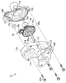
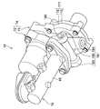
- FIG. 1 is a schematic configuration diagram of a vehicle brake system. It is a side view of a motor cylinder device. It is a disassembled perspective view of a motor cylinder apparatus. It is a disassembled perspective view of a driving force transmission part. It is the perspective view seen from the slanting lower part of the motor cylinder device. It is a disassembled perspective view for demonstrating the method of attaching a motor cylinder apparatus to a vehicle body. It is a side view of the motor cylinder apparatus which concerns on the modification of 1st Embodiment.
- FIG. 23 is a partially omitted front view showing a state where the connector is inverted 180 degrees from the state of FIG. 22 and arranged on the other side of the electric motor. It is a partially-omission front view which shows the state which inclined and arrange
- FIG. 26 is a perspective view of the motor cylinder device shown in FIG. 25. It is a side view of the motor cylinder device. It is a disassembled perspective view of the motor cylinder device.
- FIG. 53 is a diagram showing an arrangement configuration of the motor cylinder device shown in FIG. 52 on a vehicle body.
- FIG. 1 is a diagram showing an arrangement configuration in a vehicle V of a vehicle brake system to which a vehicle body mounting structure for an electric brake actuator according to a first embodiment of the present invention is applied. Note that the front, rear, left and right directions of the vehicle V are indicated by arrows in FIG.
- the vehicle brake system 10 transmits a hydraulic signal for a normal operation and a by-wire type brake system that transmits an electric signal to operate the brake, and for a fail-safe operation. It is configured with both of the traditional hydraulic brake systems that actuate the brakes.
- the vehicle brake system 10 includes an input device 14 to which an operator (driver) brake operation is input, and an electric motor that generates brake hydraulic pressure based on at least an electric signal corresponding to the brake operation.
- a motor cylinder device 16 as a brake actuator, and a vehicle stability assist device 18 (hereinafter referred to as a VSA device) as a vehicle behavior stabilization device that assists in stabilizing the behavior of the vehicle based on the brake fluid pressure generated by the motor cylinder device 16 18, VSA (registered trademark).
- VSA vehicle stability assist device
- the motor cylinder device 16 may include means for generating a hydraulic pressure based on not only an electric signal corresponding to a driver's brake operation but also an electric signal corresponding to another physical quantity.
- the electrical signal corresponding to the other physical quantity is, for example, an ECU (Electronic Control Unit) that determines the situation around the vehicle V with a sensor or the like without depending on the driver's brake operation, as in an automatic brake system. A signal for avoiding a collision of the vehicle V and the like.
- the input device 14 is applied here to a right-hand drive vehicle, and is fixed to the right side of the dashboard 2 in the vehicle width direction via a bolt or the like.
- the input device 14 may be applied to a left-hand drive vehicle.
- the motor cylinder device 16 is disposed on the left side in the vehicle width direction opposite to the input device, and is attached to the vehicle body 1 such as the left side frame via a mounting bracket 190 (see FIG. 7).
- the VSA device 18 suppresses, for example, an ABS (anti-lock braking system) function for preventing wheel lock during braking, a TCS (traction control system) function for preventing wheel slipping during acceleration, and a side slip during turning.
- ABS anti-lock braking system
- TCS traction control system
- the vehicle body is attached to the vehicle body via a bracket at the right front end in the vehicle width direction.
- an ABS device having only an ABS function for preventing wheel lock during braking may be connected.
- Detailed configurations of the input device 14, the motor cylinder device 16, and the VSA device 18 will be described later.
- These input device 14, motor cylinder device 16, and VSA device 18 are provided in a structure mounting chamber R in which a structure 3 such as an engine or a traveling motor provided in front of the dashboard 2 of the vehicle V is mounted.
- the pipes 22a to 22f are arranged separately from each other.
- the vehicle brake system 10 can be applied to any of front-wheel drive vehicles, rear-wheel drive vehicles, and four-wheel drive vehicles. Further, as a by-wire brake system, the input device 14 and the motor cylinder device 16 are electrically connected to a control means (not shown) through a harness (not shown).
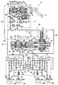
- FIG. 2 is a schematic configuration diagram of the vehicle brake system 10. The hydraulic path will be described.
- the connection port 20a of the input device 14 and the connection point A1 are connected by the first piping tube 22a with the connection point A1 in FIG. 2 as a reference, and the output port 24a of the motor cylinder device 16 And the connection point A1 are connected by the second piping tube 22b, and the introduction port 26a of the VSA device 18 and the connection point A1 are connected by the third piping tube 22c.
- connection point A2 in FIG. 2 With reference to another connection point A2 in FIG. 2, the other connection port 20b of the input device 14 and the connection point A2 are connected by the fourth piping tube 22d, and the other output port 24b of the motor cylinder device 16 is connected.
- the connection point A2 is connected by the fifth piping tube 22e, and the other introduction port 26b of the VSA device 18 and the connection point A2 are connected by the sixth piping tube 22f.
- the VSA device 18 is provided with a plurality of outlet ports 28a to 28d.
- the first outlet port 28a is connected to the wheel cylinder 32FR of the disc brake mechanism 30a provided on the right front wheel by the seventh piping tube 22g.
- the second outlet port 28b is connected to the wheel cylinder 32RL of the disc brake mechanism 30b provided on the left rear wheel by the eighth piping tube 22h.
- the third outlet port 28c is connected to the wheel cylinder 32RR of the disc brake mechanism 30c provided on the right rear wheel by the ninth piping tube 22i.
- the fourth outlet port 28d is connected to the wheel cylinder 32FL of the disc brake mechanism 30d provided on the left front wheel by the tenth piping tube 22j.
- brake fluid is supplied to the wheel cylinders 32FR, 32RL, 32RR, 32FL of the disc brake mechanisms 30a-30d by the piping tubes 22g-22j connected to the outlet ports 28a-28d, and the wheel cylinders 32FR, As the hydraulic pressure in 32RL, 32RR, and 32FL increases, each wheel cylinder 32FR, 32RL, 32RR, and 32FL is actuated to the corresponding wheel (right front wheel, left rear wheel, right rear wheel, left front wheel). A braking force is applied.
- the vehicle brake system 10 is provided so as to be mountable on various vehicles including, for example, an automobile driven by only an engine (internal combustion engine), a hybrid automobile, an electric automobile, and a fuel cell automobile.
- the input device 14 includes a tandem master cylinder 34 that can generate hydraulic pressure by operating the brake pedal 12 by the driver, and a first reservoir 36 attached to the master cylinder 34.
- a tandem master cylinder 34 that can generate hydraulic pressure by operating the brake pedal 12 by the driver, and a first reservoir 36 attached to the master cylinder 34.
- two pistons 40a and 40b spaced apart from each other by a predetermined distance along the axial direction of the cylinder tube 38 are slidably disposed.
- One piston 40 a is disposed close to the brake pedal 12 and is connected to the brake pedal 12 via a push rod 42. Further, the other piston 40b is arranged farther from the brake pedal 12 than the one piston 40a.
- a pair of piston packings 44a and 44b are mounted on the outer peripheral surfaces of the one and the other pistons 40a and 40b via annular step portions, respectively.
- a spring member 50a is disposed between the one and the other pistons 40a and 40b, and another spring member 50b is disposed between the other piston 40b and the side end portion of the cylinder tube 38. Is done.
- packing may be provided on the inner peripheral surface of the cylinder tube 38.
- the cylinder tube 38 of the master cylinder 34 is provided with two supply ports 46a and 46b, two relief ports 52a and 52b, and two output ports 54a and 54b.
- each supply port 46a (46b) and each relief port 52a (52b) are provided so as to join and communicate with a reservoir chamber (not shown) in the first reservoir 36, respectively.
- a first pressure chamber 56a and a second pressure chamber 56b that generate brake fluid pressure corresponding to the depression force of the driver depressing the brake pedal 12 are provided.
- the first pressure chamber 56a is provided so as to communicate with the connection port 20a via the first hydraulic pressure path 58a, and the second pressure chamber 56b communicates with the other connection port 20b via the second hydraulic pressure path 58b. To be provided.
- a pressure sensor Pm is disposed between the master cylinder 34 and the connection port 20a upstream of the first hydraulic pressure path 58a, and a normally open type is provided downstream of the first hydraulic pressure path 58a.
- a first shut-off valve 60a composed of a (normally open type) solenoid valve is provided. This pressure sensor Pm detects the hydraulic pressure upstream of the first shutoff valve 60a on the master cylinder 34 side on the first hydraulic pressure path 58a.
- a second shutoff valve 60b composed of a normally open type (normally open type) solenoid valve is provided.
- a pressure sensor Pp is provided on the downstream side of the second hydraulic pressure path 58b. The pressure sensor Pp detects the hydraulic pressure downstream of the wheel cylinders 32FR, 32RL, 32RR, and 32FL from the second shutoff valve 60b on the second hydraulic pressure path 58b.
- the normal open in the first shut-off valve 60a and the second shut-off valve 60b is a valve configured such that the normal position (the position of the valve body at the time of demagnetization (non-energization)) is in the open position (normally open).
- the first shut-off valve 60a and the second shut-off valve 60b show the state at the time of excitation (the same applies to the third shut-off valve 62 described later).
- a branch hydraulic pressure path 58c branched from the second hydraulic pressure path 58b is provided in the second hydraulic pressure path 58b between the master cylinder 34 and the second shutoff valve 60b, and the branched hydraulic pressure path 58c includes A third shut-off valve 62 composed of a normally closed type (normally closed type) solenoid valve and a stroke simulator 64 are connected in series.
- the normal close in the third shut-off valve 62 refers to a valve configured such that the normal position (the position of the valve body at the time of demagnetization (non-energization)) is in the closed position (normally closed).
- the stroke simulator 64 is disposed on the second hydraulic pressure path 58b and closer to the master cylinder 34 than the second shut-off valve 60b.
- the stroke simulator 64 is provided with a hydraulic pressure chamber 65 communicating with the branch hydraulic pressure path 58 c, and brake fluid (brake fluid) led out from the second pressure chamber 56 b of the master cylinder 34 through the hydraulic pressure chamber 65. ) Is provided so as to be absorbable.
- the stroke simulator 64 is a simulator that is urged by a first return spring 66a having a high spring constant, a second return spring 66b having a low spring constant, and the first and second return springs 66a and 66b arranged in series.
- a piston 68, the pedal reaction force increase gradient is set low when the brake pedal 12 is depressed, and the pedal reaction force is set high when the brake pedal 12 is depressed late, so that the pedal feeling of the brake pedal 12 is equivalent to that of the existing master cylinder. It is provided to become.
- the hydraulic pressure path is roughly divided into a first hydraulic pressure system 70a that connects the first pressure chamber 56a of the master cylinder 34 and the plurality of wheel cylinders 32FR and 32RL, a second pressure chamber 56b of the master cylinder 34, and a plurality of pressure paths.
- the second hydraulic system 70b is connected to the wheel cylinders 32RR and 32FL.
- the first hydraulic system 70a includes a first hydraulic path 58a that connects the output port 54a of the master cylinder 34 (cylinder tube 38) and the connection port 20a in the input device 14, and the connection port 20a of the input device 14 and the motor cylinder.
- Piping tubes 22a and 22b connecting the output port 24a of the device 16, piping tubes 22b and 22c connecting the output port 24a of the motor cylinder device 16 and the introduction port 26a of the VSA device 18, and a lead-out port of the VSA device 18
- the pipe tubes 22g and 22h connect the 28a and 28b and the wheel cylinders 32FR and 32RL, respectively.
- the second hydraulic system 70b includes a second hydraulic path 58b that connects the output port 54b of the master cylinder 34 (cylinder tube 38) in the input device 14 and the other connection port 20b, and another connection port of the input device 14.
- Piping tubes 22d and 22e that connect 20b and the output port 24b of the motor cylinder device 16
- piping tubes 22e and 22f that connect the output port 24b of the motor cylinder device 16 and the introduction port 26b of the VSA device 18
- the hydraulic path is constituted by the first hydraulic system 70a and the second hydraulic system 70b, so that the wheel cylinders 32FR and 32RL and the wheel cylinders 32RR and 32FL are independently operated, Mutually independent braking forces can be generated.
- the motor cylinder device 16 includes an actuator mechanism 74 including an electric motor 72 and a driving force transmission unit 73, and a cylinder mechanism 76 biased by the actuator mechanism 74.
- the driving force transmission unit 73 of the actuator mechanism 74 includes a gear mechanism (deceleration mechanism) 78 that transmits the rotational driving force of the electric motor 72, a ball screw shaft 80a that converts the rotational driving force into a linear driving force, and A ball screw structure 80 including a ball 80b.
- the cylinder mechanism 76 includes a substantially cylindrical cylinder body 82 and a second reservoir 84 attached to the cylinder body 82.
- the second reservoir 84 is connected to the first reservoir 36 attached to the master cylinder 34 of the input device 14 by a piping tube 86, and the brake fluid stored in the first reservoir 36 is passed through the piping tube 86 to the second reservoir 84.
- 84 is provided so as to be supplied in the inside.
- a first slave piston 88a and a second slave piston 88b that are spaced apart from each other by a predetermined distance along the axial direction of the cylinder body 82 are slidably disposed.
- the first slave piston 88a is disposed in the vicinity of the ball screw structure 80, contacts the one end of the ball screw shaft 80a, and is displaced in the direction of the arrow X1 or X2 integrally with the ball screw shaft 80a.
- the second slave piston 88b is arranged farther from the ball screw structure 80 side than the first slave piston 88a.
- a pair of slave piston packings 90a and 90b are respectively attached to the outer peripheral surfaces of the first and second slave pistons 88a and 88b via annular step portions.
- a first back chamber 94a and a second back chamber 94b are formed between the pair of slave piston packings 90a and 90b, respectively, and communicate with reservoir ports 92a and 92b described later.
- a first return spring 96a is disposed between the first and second slave pistons 88a and 88b, and a second return spring is provided between the second slave piston 88b and the side end of the cylinder body 82. 96b is disposed.
- the cylinder body 82 of the cylinder mechanism 76 is provided with two reservoir ports 92a and 92b and two output ports 24a and 24b.
- the reservoir port 92a (92b) is provided so as to communicate with a reservoir chamber (not shown) in the second reservoir 84.
- a first hydraulic pressure chamber 98a that generates a brake hydraulic pressure output from the output port 24a to the wheel cylinders 32FR and 32RL side, and the other output port 24b to the wheel cylinders 32RR and 32FL side.
- a second hydraulic pressure chamber 98b for generating the output brake hydraulic pressure is provided.
- a regulating means 100 is provided between the first slave piston 88a and the second slave piston 88b to regulate the maximum distance and the minimum distance between the first slave piston 88a and the second slave piston 88b.
- the second slave piston 88b is provided with a stopper pin 102 that restricts the sliding range of the second slave piston 88b and prevents an overreturn to the first slave piston 88a. At the time of backup when braking with the generated brake fluid pressure, the failure of another system is prevented when one system fails.
- the VSA device 18 is a well-known one, and a first brake system that controls a first hydraulic system 70a connected to disc brake mechanisms 30a and 30b (wheel cylinder 32FR and wheel cylinder 32RL) of the right front wheel and the left rear wheel. 110a and a second brake system 110b for controlling the second hydraulic system 70b connected to the disc brake mechanisms 30c, 30d (wheel cylinder 32RR, wheel cylinder 32FL) of the right rear wheel and the left front wheel.
- the first brake system 110a is composed of a hydraulic system connected to a disc brake mechanism provided on the left front wheel and the right front wheel
- the second brake system 110b is a disc provided on the left rear wheel and the right rear wheel.
- a hydraulic system connected to the brake mechanism may be used.
- first brake system 110a is composed of a hydraulic system connected to a disc brake mechanism provided on the right front wheel and the right rear wheel on one side of the vehicle body
- second brake system 110b is composed of a left front wheel and a left rear wheel on the vehicle body side.
- a hydraulic system connected to a disc brake mechanism provided on the wheel may be used.
- first brake system 110a and the second brake system 110b have the same structure, the corresponding parts in the first brake system 110a and the second brake system 110b are assigned the same reference numerals, and The description of the second brake system 110b will be appropriately added in parentheses, with a focus on the description of the first brake system 110a.
- the first brake system 110a (second brake system 110b) has a first common hydraulic pressure path 112 and a second common hydraulic pressure path 114 that are common to the wheel cylinders 32FR, 32RL (32RR, 32FL).
- the VSA device 18 includes a regulator valve 116 formed of a normally open type solenoid valve disposed between the introduction port 26a and the first common hydraulic pressure path 112, and arranged in parallel with the regulator valve 116 from the introduction port 26a side.
- a first check valve 118 that permits the flow of brake fluid to the first common hydraulic pressure passage 112 side (blocks the flow of brake fluid from the first common hydraulic pressure passage 112 side to the introduction port 26a side);
- a first in-valve 120 composed of a normally open type solenoid valve disposed between the common hydraulic pressure path 112 and the first outlet port 28a, and a first inlet valve 120 disposed in parallel with the first inlet valve 120 from the first outlet port 28a side.
- a second in-valve comprising a second check valve 122 (which prevents the flow of brake fluid to the 8a side) and a normally open type solenoid valve disposed between the first common hydraulic pressure passage 112 and the second outlet port 28b.
- 124 and the second inlet valve 124 are arranged in parallel to allow the brake fluid to flow from the second lead-out port 28b side to the first common hydraulic pressure path 112 side (second lead-out from the first common hydraulic pressure path 112 side).
- a third check valve 126 for inhibiting the flow of brake fluid to the port 28b side.
- the VSA device 18 includes a first out valve 128 including a normally closed solenoid valve disposed between the first outlet port 28a and the second common hydraulic pressure path 114, a second outlet port 28b, and a second outlet port 28b.
- a second out valve 130 composed of a normally closed solenoid valve disposed between the common hydraulic pressure path 114, a reservoir 132 connected to the second common hydraulic pressure path 114, and a first common hydraulic pressure path 112; It is arranged between the second common hydraulic pressure path 114 and allows the brake fluid to flow from the second common hydraulic pressure path 114 side to the first common hydraulic pressure path 112 side (from the first common hydraulic pressure path 112 side).
- a second check valve 134 (which blocks the flow of brake fluid to the second common hydraulic pressure path 114 side) and a second check valve 134 disposed between the fourth check valve 134 and the first common hydraulic pressure path 112.
- a pump 136 that supplies brake fluid from the fluid pressure path 114 side to the first common fluid pressure path 112 side, a suction valve 138 and a discharge valve 140 provided before and after the pump 136, and a motor M that drives the pump 136 And a suction valve 142 disposed between the second common hydraulic pressure path 114 and the introduction port 26a.
- the brake fluid generated in the first hydraulic chamber 98a of the motor cylinder device 16 is output from the output port 24a of the motor cylinder device 16 on the hydraulic pressure path close to the introduction port 26a.
- a pressure sensor Ph for detecting pressure is provided. Detection signals detected by the pressure sensors Pm, Pp, and Ph are introduced into control means (not shown).
- the vehicle brake system 10 according to the present embodiment is basically configured as described above. Next, the operation and effect will be described.
- the first shut-off valve 60a and the second shut-off valve 60b which are normally open type solenoid valves, are closed by excitation, and the third shut-off solenoid valve is the third.
- the shut-off valve 62 is opened by excitation (see FIG. 2). Accordingly, since the first hydraulic pressure system 70a and the second hydraulic pressure system 70b are blocked by the first cutoff valve 60a and the second cutoff valve 60b, the brake hydraulic pressure generated in the master cylinder 34 of the input device 14 is applied to the disc brake. There is no transmission to the wheel cylinders 32FR, 32RL, 32RR, 32FL of the mechanisms 30a-30d.
- the brake hydraulic pressure generated in the second pressure chamber 56b of the master cylinder 34 is transmitted to the hydraulic pressure chamber 65 of the stroke simulator 64 via the branch hydraulic pressure path 58c and the third shut-off valve 62 in the valve open state. Is done.
- the simulator piston 68 is displaced against the spring force of the return springs 66a and 66b by the brake hydraulic pressure supplied to the hydraulic pressure chamber 65, so that the stroke of the brake pedal 12 is allowed and a pseudo pedal reaction is achieved. A force is generated and applied to the brake pedal 12. As a result, it is possible to obtain a brake feeling that is comfortable for the driver.
- the control means drives the electric motor 72 of the motor cylinder device 16 to urge the actuator mechanism 74 and detect the first return spring 96a.
- the 1st slave piston 88a and the 2nd slave piston 88b are displaced toward the arrow X1 direction in FIG. 2 against the spring force of the 2nd return spring 96b. Due to the displacement of the first slave piston 88a and the second slave piston 88b, the brake fluid in the first fluid pressure chamber 98a and the second fluid pressure chamber 98b is pressurized so as to be balanced to generate a desired brake fluid pressure.
- the brake hydraulic pressure in the first hydraulic pressure chamber 98a and the second hydraulic pressure chamber 98b in the motor cylinder device 16 is supplied to the disc brake mechanism 30a via the first and second inlet valves 120 and 124 in the valve open state of the VSA device 18.
- wheel cylinders 32FR, 32RL, 32RR, 32FL, and the wheel cylinders 32FR, 32RL, 32RR, 32FL are operated to apply a desired braking force to each wheel.
- the motor cylinder device 16 that functions as an electric brake actuator (power hydraulic pressure source) and a control unit such as an ECU (not shown) that performs by-wire control can operate normally.
- a so-called brake-by-wire brake system in which the disc brake mechanisms 30a to 30d are operated with the brake fluid pressure generated by the motor cylinder device 16 in the state of being shut off by the shut-off valve 60a and the second shut-off valve 60b is active.
- it can be suitably applied to a vehicle such as an electric vehicle that does not have negative pressure due to an internal combustion engine that has been used for a long time.
- the motor cylinder device 16 or the like becomes inoperable, the first cutoff valve 60a and the second cutoff valve 60b are opened, and the third cutoff valve 62 is closed so that the master cylinder 34
- the generated brake fluid pressure is transmitted to the disc brake mechanisms 30a to 30d (wheel cylinders 32FR, 32RL, 32RR, 32FL), and the disc brake mechanisms 30a to 30d (wheel cylinders 32FR, 32RL, 32RR, 32FL) are operated.
- the so-called traditional hydraulic brake system becomes active.
- FIG. 3 is a side view of the motor cylinder device 16.
- FIG. 4 is an exploded perspective view of the motor cylinder device 16.
- FIG. 5 is an exploded perspective view of the driving force transmission unit 73.
- the motor cylinder device 16 includes an electric motor 72 that is driven based on an electric signal from a control unit (not shown), a driving force transmission unit 73 that transmits a driving force by the electric motor 72, and a driving force transmission. And a cylinder mechanism 76 that applies pressure to the brake fluid by moving the first and second slave pistons 88a and 88b (see FIG. 2) in the axial direction by the driving force transmitted from the portion 73.
- the electric motor 72 is positioned above the cylinder mechanism 76. If comprised in this way, it can prevent that the oil components, such as the grease in the driving force transmission part 73, enter into the electric motor 72 by the effect
- the electric motor 72, the driving force transmission unit 73, and the cylinder mechanism 76 are configured to be separable from each other.
- the electric motor 72 has a base portion 161 to which a harness (not shown) is connected, and a plurality of through holes 162 into which the bolts 201 are inserted are formed in the base portion 161.
- a flange portion 82a is provided at the end of the cylinder body 76 on the driving force transmission portion 73 side of the cylinder body 82, and a plurality of through holes 82b through which the bolts 202 are inserted are formed in the flange portion 82a. Yes.
- the driving force transmission unit 73 includes an actuator housing 171 that accommodates a driving force transmission mechanical element (see FIG. 5) such as a gear mechanism 78 and a ball screw structure 80.
- the actuator housing 171 includes a cylinder mechanism.
- a housing 172 disposed on the 76 side and a cover 173 that covers the opening end of the housing 172 opposite to the cylinder mechanism 76 are provided.
- the housing 172 and the cover 173 of the driving force transmission unit 73 are made of a metal such as an aluminum alloy (the same applies to the cylinder body 82 of the cylinder mechanism 76).
- the housing 172 of the driving force transmission portion 73 is formed with a plurality of motor mounting screw holes (motor mounting portions) 174 for attaching the electric motor 72 to the driving force transmission portion 73. Further, a flange portion 175 is provided at an end portion of the housing 172 on the cylinder mechanism 76 side, and a cylinder mechanism attaching screw hole 176 for attaching the cylinder mechanism 76 to the driving force transmitting portion 73 is provided in the flange portion 175. A plurality of are formed.
- the electric motor 72 is attached and fixed to the driving force transmitting portion 73 by inserting the bolt 201 into the through hole 162 and screwing it into the motor mounting screw hole 174.
- the cylinder mechanism 76 is attached and fixed to the driving force transmitting portion 73 by inserting the bolt 202 through the through hole 82b and screwing it into the cylinder mechanism attaching screw hole 176.
- a gear mechanism 78 and a ball screw structure 80 are accommodated in an actuator housing 171 (see FIG. 4).
- the gear mechanism 78 includes a pinion gear 78a (see FIG. 2) fixed to the output shaft of the electric motor 72, an idle gear 78b meshed with the pinion gear 78a, and a ring gear 78c meshed with the idle gear 78b.
- the ball screw structure 80 includes a ball screw shaft 80a whose front end is in contact with the first slave piston 88a, a ball 80b (see FIG. 2) disposed in a screw groove on the ball screw shaft 80a, and a ball 80b. And a nut portion 80c screwed to the ball screw shaft 80a.
- the nut portion 80c is, for example, press-fitted and fixed to the inner peripheral surface of the ring gear 78c.
- the ball screw The structure 80 is converted into a linear driving force, and the ball screw shaft 80a can move back and forth along the axial direction.
- the housing 172 and the cover 173 of the actuator housing 171 are configured to be separable from each other.
- a plurality of through holes 177 through which the bolts 203 are inserted are formed in the housing 172 so as to be positioned around the central axis CL (see FIG. 4) of the first and second slave pistons 88a and 88b (see FIG. 2).
- a plurality of housing mounting screw holes 178 are formed at positions corresponding to the through holes 177 of the cover 173. Then, the housing 172 and the cover 173 are coupled to each other by inserting the bolt 203 through the through hole 177 and screwing it into the housing mounting screw hole 178.
- 5 indicates a bearing that rotatably supports the tip of the output shaft of the electric motor 72, and the bearing 179 is fitted into a hole 180 formed in the cover 173.
- FIG. 6 is a perspective view of the motor cylinder device 16 as viewed obliquely from below.
- FIG. 7 is an exploded perspective view for explaining a method of attaching the motor cylinder device 16 to the vehicle body.
- the motor cylinder device 16 is provided with a mount portion 181 for attaching the motor cylinder device 16 to the vehicle body 1 (see FIG. 1) such as a side frame.
- the mount portion 181 has a left mount hole 182 located on the left side, a right mount hole 183 located on the right side, and a lower mount hole located below when viewed from the cover 173 side in the direction of the central axis CL (see FIG. 4).
- the left and right mount holes 182 to 184 each have a cylindrical recess.
- the mount portion 181 has a through hole 185 formed along the common axis of the left mount hole 182 and the right mount hole 183 and having an axis perpendicular to the central axis CL (see FIG. 4).
- the mount portion 181 is provided near the center of gravity of the motor cylinder device 16. Specifically, of the electric motor 72, the driving force transmission unit 73, and the cylinder mechanism 76, a portion where the center of gravity of the motor cylinder device 16 exists (or a portion closest to the center of gravity), here, the driving force transmission unit 73 is provided with a mount 181. More specifically, the mount portion 181 is provided in the housing 172 of the driving force transmission portion 73 in which a motor mounting screw hole 174 (see FIG. 5) is formed. However, the mounting position of the mount unit 181 may be in the vicinity of the center of gravity of the motor cylinder device 16, and is not necessarily limited to the driving force transmission unit 73 or the housing 172. According to such a configuration, the vicinity of the center of gravity of the motor cylinder device 16 can be supported, and the shake can be reduced even when receiving a force such as vibration.
- the motor cylinder device 16 is attached to the vehicle body 1 such as a side frame (see FIG. 1) via a mounting bracket 190 by a mount portion 181 (see FIG. 6).
- the mounting bracket 190 includes a pair of side plates 195 and 195 for sandwiching and supporting the motor cylinder device 16 from the left and right directions by screw fastening using bolts (male thread members) 204, and both lower sides of the pair of side plates 195 and 195. And a support plate 192 constituted by a substantially horizontal bottom plate 194 that supports the intermediate portion (center portion) of the motor cylinder device 16 from below.
- the mounting bracket 190 includes a back plate 191 connected to the side plates 195 and 195 and the bottom plate 194 and extending in a substantially vertical direction, and a fixing plate 193 connected to the back plate 191 and fixed to the vehicle body. In the vicinity of the center of the back plate 191, an opening 191a through which the protruding portion of the cover 173 is inserted is formed.
- the one side plate 195 is formed with a substantially U-shaped notch 195a through which the bolt 204 can be inserted, and the other side plate 195 is formed with a through hole 195b through which the bolt 204 is inserted.
- a nut 195c to which the bolt 204 can be screwed is fixed to the outside of the through hole 195b of the side plate 195 by, for example, welding.
- a pin 194 a is erected at the center of the upper surface of the bottom plate 194.
- a second collar 197 having a long cylindrical first collar 198, a rubber bush 196, a cylindrical portion 197a and a flange 197b formed at the end thereof, And bolts 204 are used.
- the rubber bush 196 is a substantially cylindrical elastic member made of rubber that can absorb vibration and impact. It is also possible to improve the flexibility by forming irregularities on the outer peripheral surface of the rubber bush 196, for example.
- the first collar 198 is inserted and arranged in the through hole 185 of the motor cylinder device 16. Subsequently, the cylindrical portion 197a of the second collar 197 fitted into the central hole of the rubber bush 196 is fitted into the left mount hole 182 and the right mount hole 183, respectively. Further, the rubber bush 196 is fitted into the lower mount hole 184 and attached. Then, the motor cylinder device 16 is installed on the bottom plate 194 of the mounting bracket 190 so that the pin 194a is inserted into the central hole of the rubber bush 196 mounted in the lower mount hole 184. Thus, the lower mount hole 184 supports the intermediate portion of the motor cylinder device 16 from below.
- a female screw hole is formed on the bottom surface of the lower mount hole 184, and a cylindrical collar is inserted into the central hole of the rubber bush 196 instead of the pin 194a, and a bolt or the like is provided from below the through hole formed in the bottom plate 194. It is also possible to insert a screw member and fasten the screw.
- the rubber bush 196 and the second collar 197 mounted in the left mount hole 182 and the right mount hole 183 of the motor cylinder device 16 are respectively connected to the notch 195a and the through hole of the side plate 195. Facing 195b respectively. Therefore, the bolt 204 can be inserted through the notch 195a, the second collar 197, the rubber bush 196, the first collar 198, the rubber bush 196, and the second collar 197 in order and screwed into the nut 195c. At this time, the bolt 204 is inserted into the through hole 185.
- the motor cylinder device 16 In the state where the bolt 204 is inserted into the through hole 185, the motor cylinder device 16 is mounted on the bottom plate 194 such that the shaft portion of the bolt 204 passes through the notch 195 a and the head passes through the outside of the notch 195 a. You may install in. Thus, the motor cylinder device 16 is supported by the left mount hole 182 and the right mount hole 183 so as to be sandwiched between the pair of side plates 195 and 195 from the left and right directions.
- the left mount hole 182 and the right mount hole 183 are configured to be fastened to the vehicle body side by the single bolt 204 inserted through the through hole 185. Therefore, screw fastening on both the left and right opening ends of the through-hole 185 is possible with only one fastening with a single bolt 204, and attachment work is facilitated.
- the fixing plate 193 of the mounting bracket 190 is fixed to the vehicle body 1 such as a side frame (see FIG. 1) by screw fastening, welding, or the like directly or via another connecting member (not shown).
- the mount portion 181 it is possible to attach the motor cylinder device 16 to the vehicle body side while supporting the left and right three sides of the motor cylinder device 16. Further, since the mount portion 181 of the motor cylinder device 16 is floatingly supported on the vehicle body side via the rubber bush 196, vibration and impact can be absorbed.
- the mount portion 181 for attaching the motor cylinder device 16 to the vehicle body 1 such as a side frame is provided near the center of gravity of the motor cylinder device 16. Therefore, since the vicinity of the center of gravity of the motor cylinder device 16 can be supported, even when the vehicle V or the motor cylinder device 16 itself receives various forces such as vibrations and shocks, the vibration can be reduced. The displacement of the motor cylinder device 16 can be effectively suppressed. In addition, since the mount portion 181 can be concentrated near the center of gravity, less space is required for attachment, and this increases the degree of freedom for attaching the motor cylinder device 16 to the vehicle body 1 even in a narrow arrangement space.
- the mount portion 181 is provided in a portion of the motor cylinder device 16 that is configured to be separable from the cylinder mechanism 76, specifically, in the driving force transmission portion 73 that is usually heavy and has high rigidity.
- the driving force transmission part 73 provided with the mount part 181 and the cylinder mechanism 76 are made into separate structures, both can be made separately.
- the cylinder mechanism 76 is shared as it is, and only the driving force transmission portion 73 is changed. Is possible.
- the mount portion 181 is provided in a housing 172 provided with a screw hole 174 for motor attachment for attaching the electric motor 72 to the driving force transmission portion 73 (see FIG. 5). Therefore, for example, when mounted on a plurality of types of vehicles, the position and shape of the mount portion 181 and / or the attachment position in the rotation direction of the electric motor 72 according to the connection direction of the harness needs to be changed. Can be dealt with by changing only the housing 172 of the driving force transmitting portion 73 provided with the mount portion 181 and the motor mounting screw hole 174.
- FIG. 8 is a side view of a motor cylinder device 16a according to a modification of the first embodiment.
- the electric motor 72 is positioned below the cylinder mechanism 76, and the mount portion 181 (182 to 184) is provided on the upper portion of the motor cylinder device 16a. That is, the electric motor 72 and the driving force transmission unit 73 are attached to the cylinder mechanism 76 in a state where the electric motor 72 and the driving force transmission unit 73 are rotated 180 degrees around the central axis CL (see FIG. 4). If comprised in this way, since the electric motor 72 can be located below and the motor cylinder apparatus 16a can be suspendedly supported, damping performance improves.
- this invention was demonstrated based on 1st Embodiment, this invention is not limited to the structure described in the said embodiment, The structure described in the said embodiment is combined thru
- the mount portion 181 is composed of the left and right mount holes 182 to 184, but the present invention is not limited to this.
- the mount portion 181 may be any one provided near the center of gravity of the motor cylinder device 16, and the shape and number of mounts, the support direction, the fixing method using screws, pins, and the like can be changed as appropriate.
- the motor cylinder device 16 is attached to the vehicle body via the attachment bracket 190, but the present invention is not limited to this.
- the motor cylinder device 16 may be attached to the vehicle body side, for example, via another differently shaped connecting member.
- the cylinder mechanism 76 and the driving force transmission unit 73 are configured to be separable, but the present invention is not limited to this.
- the cylinder body 82 and the housing 172 may be formed by integral molding.
- FIG. 9 is a side view showing a piping tube support structure according to a second embodiment of the present invention.
- members such as the mounting bracket 190 are not shown in FIG.
- the piping tubes 22 b and 22 e through which the brake fluid flows are connected to output ports 24 a and 24 b formed in the cylinder body 82 of the cylinder mechanism 76.
- the piping tubes 22b and 22e are formed by bending a metal pipe such as a steel pipe into a predetermined shape (the same applies to other piping tubes).
- a part of the piping tubes 22b and 22e located at positions away from the connection portions 23a and 23b of the piping tubes 22b and 22e with the output ports 24a and 24b in the extending direction of the piping tubes 22b and 22e are motor cylinder devices. 16 is supported and fixed to an intermediate portion.
- the intermediate portion of the motor cylinder device 16 refers to a portion near the center that is not an end portion of the motor cylinder device 16 in the direction of the central axis CL of the first and second slave pistons 88a and 88b (see FIG. 2).
- the central axis CL is also the central axis of the cylinder mechanism 76.
- connection portions of the piping tubes 22b and 22e to the cylinder mechanism 76 and the intermediate portions of the piping tubes 22b and 22e with respect to the motor cylinder device 16 are used.
- the load is distributed to the support location.
- a clamp member 220 for holding the piping tubes 22b and 22e is provided, and motor mounting screw holes 174 and cylinder mechanism mounting screws are used as mounting portions for mounting the clamp member 220 to the motor cylinder device 16.
- a hole 176 (see FIG. 4) is provided in the housing 172 of the driving force transmission unit 73. Therefore, it is possible to support the piping tubes 22b and 22e using the clamp member 220 on the driving force transmission portion 73 that has a large weight and high rigidity.
- the motor mounting screw hole 174 and the cylinder mechanism mounting screw hole 176 also serve as mounting screw holes for the clamp member 220.
- the piping tubes 22 b and 22 e are arranged side by side around the central axis CL of the cylinder mechanism 76, are held by a single clamp member 220, and are attached to an intermediate portion of the motor cylinder device 16.
- the piping tubes 22b and 22e may be attached to the intermediate portion of the motor cylinder device 16 by two separated clamp members, respectively.
- the screw hole for mounting the clamp member may be provided separately from the screw hole 174 for mounting the motor and the screw hole 176 for mounting the cylinder mechanism.
- the clamp member 220 is formed, for example, by punching a single metal plate having elasticity such as spring steel into a predetermined shape and then bending it.
- the clamp member 220 can hold the first curved portion 220a having a substantially C-shaped cross section that can hold the piping tube 22b to which the rubber bushing 250 is attached and the piping tube 22e to which the rubber bushing 250 is attached to the inside.
- a second curved portion 220b having a substantially C-shaped cross section.
- the rubber bush 250 is a substantially cylindrical elastic member made of rubber that can absorb vibrations and shocks. It is also possible to improve the flexibility by forming irregularities on the outer peripheral surface of the rubber bush 250, for example.
- the bolts 201 and 202 are inserted into through holes (not shown) of the clamp member 220, so that a motor mounting screw hole 174 and a cylinder mechanism mounting screw hole 176 (FIG. 4) are installed.
- the clamp member 220 is attached to the motor cylinder device 16 by being screwed respectively into the reference).
- the tip ends of the piping tubes 22b and 22e are held. It connects to the output ports 24a and 24b of the cylinder mechanism 76.
- FIG. 10 is a top view showing the displacement suppressing structure of the motor cylinder device according to the second embodiment.
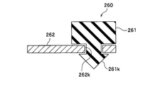
- FIG. 11 is a cross-sectional view of the load transmitting portion 260 cut along a plane parallel to the central axis CL (see FIG. 9) of the cylinder mechanism 76.
- members such as the mounting bracket 190 and the piping tubes 22 b and 22 e are not shown in the drawing (to prevent the drawing from becoming complicated) (the same applies to the subsequent drawings).
- the cylinder mechanism 76 includes a cylindrical tip portion 82 c (near the tip) that is fixed to the front end surface of the cylinder body 82.
- the tip end portion 82c is formed from a metal such as a resin or an aluminum alloy.
- the tip end portion 82c is screwed to the cylinder body 82 with a bolt 206, for example.
- a load in a direction orthogonal to the central axis CL (see FIG. 9) is applied to the tip end portion 82c by fitting the base portion of the shaft of the bolt 206 into a through hole formed in the tip end portion 82c. It is set as the structure which does not slip.
- the male thread portion formed on the front end side of the shaft of the bolt 206 is formed at the front end of the cylinder body 82 and is screwed into the screw hole.
- the fixing method of the tip end portion 82c to the front end surface of the cylinder body 82 is not limited to screw fastening, and various fixing methods such as adhesion and welding can be adopted. Further, the tip end portion 82 c may be formed by integral molding at the front end of the cylinder body 82. Furthermore, a part of the front end side of the cylinder body 82 may be used as the tip end portion 82c.
- the displacement suppressing structure of the motor cylinder device 16 is formed between the motor cylinder device 16 and the vehicle body 1 such as a side frame (see FIG. 1), and transmits the load from the motor cylinder device 16 to the vehicle body 1.
- a load transmission unit 260 is included. And the load transmission part 260 is provided independently of the mount part 181 (refer FIG. 6).
- the load transmission unit 260 includes an elastic body 261 capable of contacting the motor cylinder device 16 and a bracket 262 as a support member that supports the elastic body 261. Such a load transmission unit 260 has a central axis. A plurality of CLs are arranged around CL (see FIG. 9). In the present embodiment, the load transmitting portion 260 can be brought into contact with the tip end portion 82c of the cylinder mechanism 76, and a pair of load transmitting portions 260 are arranged on the left and right of the tip end portion 82c of the cylinder mechanism 76 with the central axis CL (see FIG. 9) interposed therebetween. Yes.
- the gap G1 is a displacement that does not hinder the function of the motor cylinder device 16 such that the stress generated in the piping tubes 22b and 22e (see FIG. 9) connected to the motor cylinder device 16 is less than the allowable stress, for example. It is set to a distance that can be suppressed.
- the bracket 262 is formed with a through hole 262k for holding the elastic body 261.
- An engaging portion 261k having an outer diameter slightly larger than the through hole 262k is formed on the end surface of the elastic body 261 on the bracket 262 side.
- the elastic body 261 can be easily held by the bracket 262 by pushing the engaging portion 261k of the elastic body 261 into the through hole 262k of the bracket 262.
- the number of through holes 262k and engaging portions 261k installed is arbitrary, and may be one or more. However, the elastic body 261 may be held by the bracket 262 by other methods such as screw fastening and adhesion.
- the elastic body 261 has a substantially rectangular parallelepiped shape, but it is preferable that the surface of the motor cylinder device 16 facing the tip portion 82c is formed in a curved shape corresponding to the outer peripheral surface of the tip portion 82c. If comprised in this way, the contact area at the time of the elastic body 261 contact
- the elastic body 261 is a rubber cushioning member that can absorb vibrations and shocks. Note that it is also possible to improve the flexibility by forming irregularities on the surface of the elastic body 261 facing the distal end portion 82c.
- the bracket 262 is made of a metal such as steel with high rigidity.
- the bracket 262 has, for example, a plate shape, but is appropriately processed into a shape that does not interfere with other members.
- the bracket 262 is fixed to the vehicle body 1 such as a side frame (see FIG. 1) by screw fastening, welding, or the like, directly or via another connecting member (not shown).
- the displacement suppressing structure of the motor cylinder device 16 configured as described above operates as follows. That is, when receiving various forces such as vibration and impact of the vehicle V and the motor cylinder device 16 which are larger than usual, the vehicle body 1 such as a side frame (see FIG. 1) is mounted by the mount portion 181 (see FIG. 6). ) Is displaced. When the displacement amount of the motor cylinder device 16 becomes equal to or larger than the gap G1, the motor cylinder device 16 comes into contact with the load transmission portion 260 provided independently of the mount portion 181. Is transmitted to the vehicle body 1 (see FIG. 1) such as a side frame. Thereby, the displacement of the motor cylinder device 16 is suppressed.
- the present embodiment it is formed between the motor cylinder device 16 and the vehicle body 1 such as a side frame (see FIG. 1), and transmits the load from the motor cylinder device 16 to the vehicle body 1.
- the load transmission portion 260 is provided independently of the mount portion 181 (see FIG. 6).
- the displacement of the motor cylinder device 16 can be suppressed when receiving a force such as vibration.
- the motor cylinder device 16 receives a force such as vibration of a normal magnitude, the sound and vibration of the motor cylinder device 16 are reduced by the support in the mount portion 181 (see FIG. 6), and more than usual.
- the load from the motor cylinder device 16 is received by the load transmitting portion 260, so that the displacement of the motor cylinder device 16 can be suppressed. Since the displacement of the motor cylinder device 16 can be suppressed in this way, for example, it is possible to reduce the stress generated in the piping tubes 22b and 22e (see FIG. 9) connected to the motor cylinder device 16.
- the load transmitting portion 260 can be brought into contact with the tip end portion 82c of the cylinder mechanism 76. Therefore, the displacement around the tip of the cylinder mechanism 76, particularly the displacement that can occur around the mount portion 181 (see FIG. 6) can be more effectively suppressed. Particularly in the present embodiment, the displacement in the left-right direction (see FIG. 7) about the vicinity of the tip of the cylinder mechanism 76 can be more effectively suppressed.
- the load transmission unit 260 includes an elastic body 261 that can contact the cylinder mechanism 76 and a bracket 262 that supports the elastic body 261. Therefore, a force such as vibration can be attenuated by the elastic body 261, and displacement generated in the cylinder mechanism 76 can be more effectively suppressed. Further, the cylinder mechanism 76 itself can be protected.
- the load from the motor cylinder device 16 is applied to the vehicle body 1 such as a side frame (see FIG. 1). ) Is provided so as to be transmitted. Therefore, when a relatively small force such as vibration is received, the force such as the vibration is not transmitted to the load transmission unit 260, so that the propagation of vibration and the generation of sound through the load transmission unit 260 can be prevented. It becomes possible.
- FIG. 12 is a top view showing the displacement suppressing structure of the motor cylinder device according to the first modification of the second embodiment.
- the detailed description of the configurations and operations similar to those of the second embodiment shown in FIGS. 9 to 11 will be omitted as they are incorporated in the first modification, and different points will be described (further described below). The same applies to the modified example).
- the first modification of the second embodiment is different from the second embodiment in that the elastic body 261a and the bracket 262a of the load transmitting portion 260a are separately arranged.
- the elastic body 261a is fixed to the outer peripheral surface of the tip end portion 82c of the motor cylinder device 16 by a method such as adhesion, engagement, and screw fastening.
- the through-hole for holding the elastic body 261a is not formed in the bracket 262a, and the bracket 262a is disposed at a position facing the side surface of the elastic body 261a.
- the gap G1 is provided between the motor cylinder apparatus 16 and the bracket 262a which is a part of the load transmission part 260a.
- the elastic body 261 is provided on the bracket 262 in the second embodiment, but the elastic body 261a is provided on the motor cylinder device 16 in the first modification of the second embodiment. According to such a first modification of the second embodiment, the same operational effects as those of the second embodiment can be achieved.
- FIG. 13 is a side view showing a displacement suppressing structure of a motor cylinder device according to a second modification of the second embodiment.
- the second modification of the second embodiment is different from the second embodiment in that a pair of load transmission portions 260b are arranged above and below the tip end portion 82c of the cylinder mechanism 76 with the central axis CL (see FIG. 9) interposed therebetween. It is different. According to such a second modification of the second embodiment, the same effects as those of the second embodiment can be obtained, and in particular, the vertical displacement around the tip of the cylinder mechanism 76 is more effective. Can be suppressed.
- FIG. 14 is a top view showing a displacement suppressing structure of a motor cylinder device according to a third modification of the second embodiment.
- the load transmission portion 260c can contact not only the tip end portion 82c of the motor cylinder device 16 but also the driving force transmission portion 73, and sandwich the center axis CL (see FIG. 9).
- the second embodiment is different from the second embodiment in that a pair is disposed not only on the left and right sides of the distal end portion 82c of the cylinder mechanism 76 but also on the left and right sides of the driving force transmitting portion 73.
- a gap G2 is provided.
- the gap G2 may be set smaller than the gap G1 in order to stabilize the motor cylinder device 16 as a whole and suppress displacement, for example.
- the load transmitting portion 260c has a driving force that is usually heavy and has high rigidity.
- the load from the transmission part 73 can be received, and the displacement of the right and left as the motor cylinder apparatus 16 whole can be suppressed more effectively.
- FIG. 15 is a top view showing a displacement suppressing structure of a motor cylinder device according to a fourth modification of the second embodiment.
- the fourth modified example of the second embodiment is different from the third modified example of the second embodiment in that the elastic body 261a and the bracket 262a of the load transmitting portion 260d are arranged separately.
- the configurations of the separated elastic body 261a and bracket 262a are the same as those in the second embodiment, and thus the description thereof is omitted. According to such a fourth modification of the second embodiment, the same operational effects as those of the third modification of the second embodiment can be achieved.
- FIG. 16 is a side view showing a displacement suppressing structure of a motor cylinder device according to a fifth modification of the second embodiment.
- the load transmitting portion 260e can contact not only the tip end portion 82c of the motor cylinder device 16 but also the driving force transmitting portion 73, and sandwich the center axis CL (see FIG. 9).
- the second embodiment is different from the second modified example in that a pair is arranged above and below the driving force transmitting portion 73 as well as above and below the tip end portion 82c of the cylinder mechanism 76.
- the load transmitting portion 260e has a large normal weight. It is possible to receive a load from the highly rigid driving force transmission unit 73, and it is possible to more effectively suppress the vertical displacement of the motor cylinder device 16 as a whole. However, it is also possible to adopt a configuration in which a pair of load transmitting portions 260e are disposed only above and below the driving force transmitting portion 73 of the cylinder mechanism 76 with the central axis CL (see FIG. 9) interposed therebetween.
- FIG. 17 is a top view showing a displacement suppressing structure of a motor cylinder device according to a sixth modification of the second embodiment.
- the load transmitting portion 260f can contact not only the tip end portion 82c of the motor cylinder device 16 but also the base portion 161 of the electric motor 72, and the center axis CL (see FIG. 9).
- the second embodiment is different from the second embodiment in that a pair is disposed not only on the left and right sides of the distal end portion 82 c of the cylinder mechanism 76 but also on the left and right sides of the base portion 161 of the electric motor 72.
- the load transmitting portion 260f is an electric motor to which a harness (not shown) is connected. Since it is disposed in the vicinity of the connector 72, the displacement in the vicinity of the connector can be suppressed, and the load on the harness can be reduced.
- a pair of load transmitting portions 260f are disposed only on the left and right of the base portion 161 of the electric motor 72 of the cylinder mechanism 76 with the central axis CL (see FIG. 9) interposed therebetween.
- the location of the load transmission unit including the elastic body and the bracket can be changed as appropriate.
- any two or more of the load transmitting portions 260, 260a to 260f in the displacement suppressing structure of the motor cylinder device according to the second embodiment and the first to sixth modifications of the second embodiment are arbitrarily combined and employed. It is possible.
- the load transmitting portion is not limited to the left and right, top and bottom arrangement of the motor cylinder device 16, and may be arranged at an equally divided position such as a three-way division in the circumferential direction around the central axis CL. Good.
- the load transmission unit may be disposed, for example, at a position facing the housing 172 in the vicinity of the output shaft of the electric motor 72, for example. In this way, the displacement of the electric motor 72 can be more effectively suppressed.
- the gap is provided between the motor cylinder device 16 and the load transmission unit when the motor cylinder device 16 is not displaced.
- the present invention is not limited to this. It is also possible to configure the load transmission unit to contact the motor cylinder device 16 in advance, and even with such a configuration, the displacement of the motor cylinder device 16 is suppressed when receiving a force such as vibration. be able to.
- the mount portion 181 includes the left and right mount holes 182 to 184, but the present invention is not limited to this.
- the shape and number of mounts, the support direction, the fixing method using screws, pins, and the like can be appropriately changed.
- FIG. 18 is a schematic configuration diagram of a vehicle brake system in which a motor cylinder device according to a third embodiment of the present invention is incorporated. Since the vehicle brake system 10 shown in FIG. 18 is substantially the same as that of the first embodiment, the description thereof will be omitted as appropriate, and different parts will be mainly described in the following.
- FIG. 19 is a perspective view of the motor cylinder device shown in FIG. 18,
- FIG. 20 is an exploded perspective view of the motor cylinder device, and
- FIG. 21 is a front view of the motor cylinder device.
- the motor cylinder device 16 functioning as an electric brake actuator has an actuator mechanism 74 including an electric motor 72 and a cylinder mechanism 76 biased by the actuator mechanism 74, as shown in FIG.
- the actuator mechanism 74 has an actuator housing 171.
- the actuator housing 171 includes a connecting portion 77 to which the electric motor 72 is connected and a flange portion 175 to which the cylinder body 82 is connected.
- the flange portion 175 is fastened to the other end portion of the cylinder body 82 made of a substantially rhomboid plate via a pair of screw members (bolts) 202 fastened to the pair of screw holes 176.
- a rotation angle sensor 73 a provided in an end block 161 described later of the electric motor 72 and detecting the rotation angle of the electric motor 72, and the electric motor 72.
- a gear mechanism (deceleration mechanism) 78 in which a plurality of gears including a gear coupled to the output shaft (motor shaft) of the motor mesh with each other to transmit the rotational driving force of the electric motor 72, and the rotational drive via the gear mechanism 78.
- the ball screw structure 80 including the ball screw shaft 80a and the ball 80b that move forward and backward along the axial direction by transmitting the force is accommodated.
- the rotation angle sensor 73a is configured by, for example, a resolver or a rotary encoder.
- the connecting portion 77 of the actuator housing 171 has a substantially circular opening 83 and four portions provided in the vicinity of the four corners of the rectangular side wall 85 when viewed from the cylinder body 82 side. Screw holes 87a to 87d are respectively formed. In this case, as will be described later, it is electrically driven through a pair of screw members (bolts) 201 fastened to a pair of screw holes 87a, 87b (or 87c, 87d) selected from the four screw holes 87a-87d.
- a motor 72 is integrally coupled to the actuator housing 171.
- the remaining pair of screw holes 87c and 87d (or 87a and 87b) that are not selected are exposed to the outside as they are.
- the number of the screw holes may be appropriately drilled when used, and it is not necessary to provide four screw holes in advance.
- a plurality of screw holes 87a to 87d formed in the rectangular side wall 85 and a pair of screw members 201 fastened to the screw holes 87a to 87d function as changing means for changing the arrangement direction of the connector 99.
- the change in the arrangement direction of the connector 99 will be described in detail later.
- the electric motor 72 includes, for example, a well-known servo motor or the like, and includes a motor casing 72a formed in a bottomed cylindrical shape, and an insertion hole (through hole) 162 through which the screw member 201 is inserted.
- An end block (base portion) 161 that is integrally connected, and a connector 99 that is connected to the end block 161 via a connection pin (not shown) protruding outward from a side surface of the end block 161 are provided.
- a rotor, a stator, a magnet, and the like are disposed in the motor casing 72a.
- a connector 99 that is electrically connected to the electric motor 72 is disposed on the side surface of the actuator housing 171.
- the connector 99 is formed integrally with the motor casing 72 a (which may include the end block 161) and is fixed to the connecting portion 77 of the actuator housing 171.
- the connector 99 by arranging the connector 99 outside the actuator housing 171 and on the side surface (side portion) thereof, the access to the connector 99 is simplified and the accessibility can be improved.
- the connector 99 includes a power connector 99a for power supply that supplies power to the electric motor 72, and a sensor connector 99b for sensor that supplies a detection signal detected by the rotation angle sensor 73a to control means (not shown).
- a plurality of connectors having different uses are divided and configured.
- the divided power connector 99a and sensor connector 99b are arranged in parallel in the same direction, and are provided so as to extend in a direction substantially orthogonal to the axis of the output shaft (motor shaft) of the electric motor 72.
- the power connector 99a has a rectangular tubular connector housing 101a, and a plurality of connector pins 103 that are electrically connected to the electric motor 72 are accommodated in the connector housing 101a.
- the sensor connector 99b has a rectangular tubular connector housing 101b, and a plurality of connector pins (not shown) electrically connected to the rotation angle sensor 73a are provided inside the connector housing 101b.
- the power connector 99a is connected to a connecting connector 107a that is detachable along the direction of the arrow (attachment / detachment direction).
- the connecting connector 107 a is provided with a terminal portion (not shown) through which the connector pin 103 (see FIG. 20) is inserted and electrically connected to the connector pin 103.
- the sensor connector 99b is connected with a detachable connecting connector 107b along an arrow direction (detachment direction).
- the connection connector 107b is provided with a terminal portion (not shown) through which a connector pin (not shown) is inserted and electrically connected to the connector pin.
- One connection connector 107a is electrically connected to a power source such as a battery by a harness (not shown), and the other connection connector 107b is electrically connected to control means (not shown) by a harness (not shown).
- the cylinder mechanism 76 has a substantially cylindrical cylinder main body 82 and a second reservoir 84 attached directly to the outer peripheral surface of the cylinder main body 82.
- the cylinder body 82 is provided so as to be separable from the actuator housing 171, and the actuator housing 171 and the cylinder body 82 constitute an electric brake actuator body.
- the second reservoir 84 is connected to the first reservoir 36 attached to the master cylinder 34 of the input device 14 by a piping tube 86, and the brake fluid stored in the first reservoir 36 is passed through the piping tube 86 to the second reservoir 84.
- 84 is provided so as to be supplied in the inside.
- the second reservoir 84 has a reservoir body 109, and the reservoir body 109 is provided with a nipple 111 to which a piping tube 86 is connected. Brake fluid is introduced into the reservoir body 109 through the nipple 111, and the extending direction of the nipple 111 is the brake fluid introduction direction. Note that the direction in which the nipple 111 is taken out (extending direction) from the reservoir body 109 can be set in various arbitrary directions of the reservoir body 109, for example, as illustrated by the phantom line in FIG. .
- the brake fluid introduction direction to the second reservoir 84 and the connector 99 (power connector 99a and sensor connector 99b) attachment / detachment direction coincide with each other.
- the motor cylinder device 16 can be easily accessed at the time of assembly and maintenance, the accessibility can be improved, the assembly work and the maintenance work from the same direction can be facilitated, and the workability can be improved. Can do. Furthermore, the burden on the worker who performs such assembling work and maintenance work can be reduced.
- the connector 99 by arranging the connector 99 on the outer side surface (side portion) of the actuator housing 171, a space for attaching and detaching the connector 99 is ensured, and the access to the connector 99 is simplified and the accessibility is improved. Can do. As a result, the ease of use of the motor cylinder device 16 increases, and versatility can be improved.
- the accessibility can be further improved.
- the brake fluid introduction direction to the second reservoir 84 (the extending direction of the nipple 111 to which the piping tube 86 is connected) and the connector 99 (the power connector 99a and the sensor).
- FIG. 22 is a partially omitted front view showing a state in which the connector is arranged on one side of the electric motor
- FIG. 23 shows a state in which the connector is inverted 180 degrees from the state of FIG. 22 and arranged on the other side of the electric motor
- FIG. 24 is a partially omitted front view showing a state in which the connector is disposed to be inclined with respect to the electric motor.
- the pair of screw members 201 are fastened to the pair of screw holes 87 a and 87 b positioned diagonally to each other, and the electric motor 72 is fixed to the connecting portion 77.
- the upper power connector 99a and the lower sensor connector 99b are arranged side by side along the lateral direction of the electric motor 72.
- the pair of screw holes 87a and 87b is selected from the four screw holes 87a to 87d, and the remaining pair of screw holes 87c and 87d that are not selected are exposed to the outside as they are.
- the connector 99 is rotated 180 degrees around the axis (center line) CL of the electric motor 72 from the one-side arrangement state of the connector 99 shown in FIG.
- the pair of screw members 201 are fastened to the screw holes 87 a and 87 b and the electric motor 72 is fixed to the connecting portion 77.
- the sensor connector 99b on the upper side and the power connector 99a on the lower side are arranged side by side and arranged on the other side along the lateral direction of the electric motor 72.
- the electric motor 72 and the connector 99 are the same as in FIG. 22, and a pair of screw holes 87a and 87b is selected from the four screw holes 87a to 87d, and the remaining pair not selected.
- the screw holes 87c and 87d are exposed to the outside as they are.
- the pair of screw members 201 are fastened to the other pair of screw holes 87 c and 87 d positioned diagonally to each other, and the electric motor 72 is fixed to the connecting portion 77.
- the connector 99 is disposed in an inclined state with respect to the electric motor 72.
- the other pair of screw holes 87c and 87d is selected from the four screw holes 87a to 87d, and the remaining pair of screw holes 87a and 87b that are not selected are exposed to the outside as they are.
- the electric motor 72 and the connector 99 are the same as those in FIG.
- the connector 99 is provided so as to be arranged at a plurality of rotational positions with respect to the axis CL of the electric motor 72, so that, for example, the right handle at the handle position of the vehicle It becomes possible to easily cope with the specification and the left handle specification, and the versatility can be further improved.
- the connector 99 includes four screw holes 87a to 87d formed in the rectangular side wall 85 and a pair of screw members 201 that are selectively fastened to the screw holes 87a to 87d.
- a changing means for changing the arrangement direction is configured.
- the screw holes 87a to 87d to which the pair of screw members 201 are fastened are arbitrarily selected from the plurality of screw holes 87a to 87d, and the axis CL of the electric motor 72 is matched to the position of the selected screw holes 87a to 87d.
- the changing means can be configured with a simple structure, and the arrangement position of the connector 99 can be easily changed.
- the number, arrangement, and the like of the screw holes 87a to 87d and the screw member 201 are merely examples, and are not limited to the numbers shown in FIGS. 22 to 24, and may be set as appropriate. Also good.
- the connector 99 is divided into two parts including at least a power connector 99a for power supply and a sensor connector 99b for sensor, so that the detection output from the rotation angle sensor 73a is performed. Generation of noise in the signal can be suppressed, and downsizing can be achieved as compared with a case where a plurality of connectors are integrated.
- the vehicle brake system 10 provided with the motor cylinder device 16 capable of improving versatility can be obtained.
- FIG. 25 is a schematic configuration diagram of a vehicle brake system in which a motor cylinder device according to a fourth embodiment of the present invention is incorporated. Since the vehicular brake system 10 shown in FIG. 25 is substantially the same as that of the first embodiment, the description thereof will be omitted as appropriate, and different parts will be mainly described in the following.
- FIG. 26 is a perspective view of the motor cylinder device shown in FIG. 25
- FIG. 27 is a side view of the motor cylinder device
- FIG. 28 is an exploded perspective view of the motor cylinder device
- FIG. 29 is a configuration of the motor cylinder device.
- FIG. 30 is an exploded perspective view of a cylinder mechanism constituting the motor cylinder device.
- the motor cylinder device 16 functioning as an electric brake actuator includes an actuator mechanism 74 having an electric motor 72 and a driving force transmission unit 73, and a cylinder mechanism 76 biased by the actuator mechanism 74.
- the electric motor 72, the driving force transmission unit 73, and the cylinder mechanism 76 are provided in a separable manner.
- the driving force transmission unit 73 of the actuator mechanism 74 converts a gear mechanism (deceleration mechanism) 78 that transmits the rotational driving force of the electric motor 72 and converts this rotational driving force into linear motion (linear force in the linear direction). And a ball screw structure 80 that transmits to the slave pistons 88a and 88b described later.
- the electric motor 72 is driven and controlled based on a control signal (electric signal) from a control means (not shown), for example, a servo motor, and is disposed above the cylinder mechanism 76.
- a control signal electrical signal
- a control means for example, a servo motor
- the electric motor 72 includes a motor casing 72a formed in a bottomed cylindrical shape, and a base 161 integrally coupled to the motor casing 72a and connected to a harness (not shown).
- a plurality of insertion holes (through holes) 162 for inserting screw members (bolts) 201 are formed in the base portion 161, and the electric motor 72 is fastened to an actuator housing 171 described later via the screw members 201.
- the driving force transmission unit 73 includes an actuator housing 171, and mechanical elements for driving force transmission such as a gear mechanism (deceleration mechanism) 78, a ball screw structure 80, and the like are housed in a space in the actuator housing 171.
- the actuator housing 171 includes a first body (housing) 172 disposed on the cylinder mechanism 76 side and a second body that closes the opening end of the first body 172 opposite to the cylinder mechanism 76.
- the body (cover) 173 is divided.
- the actuator housing 171 and a cylinder body 82 to be described later constitute an electric brake actuator body.
- a pair of screw holes 174 for attaching the electric motor 72 to the driving force transmitting portion 73 is provided, and the pair of screw members 201 are formed in the screw holes 174.
- the electric motor 72 is fixed by fastening.
- a flange portion 175 having a substantially rhombus shape is provided at the end of the first body 172 on the cylinder mechanism 76 side, and a substantially circular opening 79 a and the cylinder mechanism 76 are attached to the flange portion 175.
- a pair of screw holes 176 are provided for this purpose.
- a pair of screw members 202 penetrating through an insertion hole (through hole) 82b of a flange portion 82a provided at the other end portion of the cylinder body 82 to be described later is screwed into the screw hole 176, thereby the cylinder.
- the mechanism 76 and the driving force transmission unit 73 are integrally coupled.
- the gear mechanism 78 includes a small-diameter pinion gear 78a (see FIG. 25) that is mounted on the output shaft of the electric motor 72, a small-diameter idle gear 78b that meshes with the pinion gear 78a, and a large-diameter that meshes with the idle gear 78b. Ring gear 78c.
- the ball screw structure 80 rolls along a ball screw shaft 80a whose one end is in contact with the first slave piston 88a of the cylinder mechanism 76 and a spiral screw groove formed on the outer peripheral surface of the ball screw shaft 80a.
- a plurality of balls 80b (see FIG. 25), a substantially cylindrical nut portion 80c fitted into the ring gear 78c and rotated integrally with the ring gear 78c, and screwed into the ball 80b, and the nut
- a pair of ball bearings 80d (see FIG. 25) that rotatably supports one end side and the other end side along the axial direction of the portion 80c are provided.
- the nut portion 80c is, for example, press-fitted and fixed to the inner diameter surface of the ring gear 78c.
- the driving force transmission unit 73 By configuring the driving force transmission unit 73 in this way, after the rotational driving force of the electric motor 72 transmitted through the gear mechanism 78 is input to the nut unit 80c, the driving force transmission unit 73 is linearly moved by the ball screw structure 80. The axial force (linear motion) of the ball screw shaft 80a is moved back and forth along the axial direction.
- the first body 172 and the second body 173 constituting the actuator housing 171 are integrally coupled via four bolts 203 and are separable from each other.
- the first body 172 is formed with an insertion hole (through hole) 177 through which the four bolts 203 are inserted, and the threaded portion of the bolt 203 is screwed into the second body 173 at a position corresponding to the insertion hole 177.
- a screw hole 178 is formed.
- first body 172 and the second body 173 are integrally fastened by screwing the bolt 203 passing through the insertion hole 177 of the first body 172 into the screw hole 178 of the second body 173.
- a circular recess (hole) 180 is provided on the upper side of the second body 173, and a bearing 179 that rotatably supports the tip of the output shaft of the electric motor 72 is attached to the circular recess 180. Is done.
- the actuator housing 171 is divided into a first body 172 and a second body 173 by using a surface substantially orthogonal to the axis CL of the cylinder body 82 of the cylinder mechanism 76 as a divided surface (see FIG. 28).
- the fastening direction of the plurality of bolts 203 is parallel to the axis (center axis) CL of the cylinder body 82, and the assembly work can be easily performed.
- the cylinder mechanism 76 has a bottomed cylindrical cylinder body 82 and a second reservoir 84 attached to the cylinder body 82.
- the second reservoir 84 is connected to the first reservoir 36 attached to the master cylinder 34 of the input device 14 by a piping tube 86, and the brake fluid stored in the first reservoir 36 is passed through the piping tube 86 to the second reservoir 84.
- 84 is provided so as to be supplied in the inside.
- the first slave piston 88a is disposed close to the ball screw structure 80 side, abuts against one end of the ball screw shaft 80a through the hole 89, and is integrated with the ball screw shaft 80a by the arrow X1 or X2. Displace in the direction.
- the second slave piston 88b is arranged farther from the ball screw structure 80 side than the first slave piston 88a.
- a pair of slave piston packings 90a and 90b are respectively attached to the outer peripheral surfaces of the first and second slave pistons 88a and 88b via annular step portions.
- a first back chamber 94a and a second back chamber 94b are formed between the pair of slave piston packings 90a and 90b, respectively, and communicate with reservoir ports 92a and 92b described later (see FIG. 25).
- a first return spring 96a is disposed between the first and second slave pistons 88a and 88b, and between the second slave piston 88b and the side end (bottom wall) of the cylinder body 82, A second return spring 96b is provided.
- the cylinder body 82 of the cylinder mechanism 76 is provided with two reservoir ports 92a and 92b and two output ports 24a and 24b.
- the reservoir port 92a (92b) is provided so as to communicate with a reservoir chamber (not shown) in the second reservoir 84.
- a first hydraulic pressure chamber 98a for controlling the brake hydraulic pressure output from the output port 24a to the wheel cylinders 32FR and 32RL side, and the other output port 24b to the wheel cylinders 32RR and 32FL side.
- a second hydraulic pressure chamber 98b for controlling the output brake hydraulic pressure is provided.
- a bolt shape that regulates the maximum stroke (maximum displacement distance) and the minimum stroke (minimum displacement distance) of the first slave piston 88a and the second slave piston 88b.
- the second slave piston 88b is engaged with a through-hole 91 that penetrates in a direction substantially perpendicular to the axis of the second slave piston 88b, and the second slave piston 88b slides.
- a stopper pin 102 that restricts the moving range and prevents an overreturn to the first slave piston 88a side is provided, and in particular, at the time of backup when braking with the brake hydraulic pressure generated in the master cylinder 34, When one system fails, the other system is prevented from failing.
- the piston guide 104 latched via the circlip which is not shown in figure is attached to the opening part of the cylinder main body 82.
- the piston guide 104 is formed with a through hole 104a through which the first piston 88a can be inserted through a clearance, and a ball screw shaft is formed by sliding the rod portion of the first piston 88a along the through hole 104a.
- the first piston 88a in contact with one end of 80a can be guided linearly.
- the coupling piston 105 is connected to the second piston 88b, and the coupling piston 105 is provided with an engagement hole (not shown) that engages the head portion 100a of the regulating means 100 formed in a bolt shape.
- FIG. 31 is a perspective view of the motor cylinder device as viewed from below
- FIG. 32 is a perspective view showing a state in which the motor cylinder device is fixed to a vehicle body frame via a fixing bracket supported at three points. .
- a mount portion 181 for supporting the motor cylinder device 16 and attaching it to, for example, a vehicle body frame.
- the mount portion 181 is positioned on the left side when viewed from the second body 173 side, and is positioned on the right side when viewed from the second body 173 side, and a first boss portion 113a protruding in a direction substantially orthogonal to the axis CL of the cylinder body 82.
- a second boss portion 113b protruding in the opposite direction to the first boss portion 113a, and a cylindrical third boss portion 113c protruding downward as viewed from the second body 173 side.
- a circular stepped hole 115 is formed in the opening of the first boss 113a and the second boss 113b provided on both the left and right sides of the first body 172.
- through holes 185 are formed so as to penetrate each other in a direction substantially perpendicular to the axis CL of the cylinder body 82.
- a support mechanism 119 shown in FIG. 32 is disposed in the stepped hole 115 and the through hole 185.
- the first boss portion 113a is located at one end portion along the axial direction of the through hole 185
- the second boss portion 113b is located at the other end portion along the axial direction of the through hole 185
- the third The boss portion 113 c is provided so as to be positioned on the vertically downward direction substantially orthogonal to the axis of the through hole 185.
- a bottomed hole (lower mount hole) 121 is formed in the third boss 113c.
- the first boss portion 113a, the second boss portion 113b, and the third boss portion 113c are integrally formed with the first body 172 by die casting using a light metal material such as an aluminum alloy, for example.
- the motor cylinder device 16 is attached to a vehicle body such as a front side frame 125, for example, via a support mechanism 119 and a fixing bracket (an electric brake actuator fixing bracket; mounting bracket) 190.
- the motor cylinder device 16 is disposed on the lower side of a dashboard (not shown) that divides a power plant room in which a vehicle drive device such as an engine and a traveling motor is housed and a cabin in the vehicle through a fixed bracket 190. It is also possible to fix.
- the support mechanism 119 includes a single collar member (first collar) 198 made of a hollow cylindrical body and inserted in the center of the through hole 185 along the axial direction of the collar member 198.
- a shaft portion (cylindrical portion) 197a and a flange 197b to be mounted in the hole portion 196a are integrally formed, and a pair of locking members (first members) in which a hole portion 197c penetrating along the axis is formed in the shaft portion 197a.
- 2 collars) 197 and one locking member 197 inserted from one side substantially orthogonal to the axis CL of the cylinder body 82 and disposed inside the through hole 185, one elastic body 196, the collar member 198, the other of Sex body 196, and includes a single bolt (fixing member) 204 which penetrates the other of the locking member 197, respectively.
- the bolt 204 has a long shaft body 204a, a head portion 204c having a threaded portion 204b at one end along the axial direction of the shaft body 204a and a washer engaged at the other end portion. Is provided.
- the fixing bracket 190 has a U-shaped vertical cross section, a pair of side plates 195 and 195 that support the first boss portion 113a and the second boss portion 113b of the motor cylinder device 16 from the left and right lateral directions, and rubber or the like.
- the motor cylinder device 16 is connected to the bottom plate 194 having a protrusion (pin) 194a to which the elastic body 196 is attached and fitted into the hole 121 of the third boss portion 113c, and the pair of side plates 195 and 195 and the bottom plate 194. And a supporting plate (back plate) 191 to be supported.
- the fixing bracket 190 has a connecting plate 137 fastened to the upper surface portion of the support plate 191 via a screw member 205 screwed into a screw hole 135 formed on the upper surface, and a bent portion bent in a substantially L shape. And a fixing plate 139 for fixing the fixing bracket 190 by being welded to the side surface of the front side frame 125.
- a substantially U-shaped groove (notch) 195a is formed on one side plate 195 located on one side, and the shaft 204a of the bolt 204 is held by being locked by the groove 195a.
- the other side plate 195 is provided with a nut 195c that is welded and fixed, and a threaded portion 204b of a bolt 204 that passes through an insertion hole (through hole) 195b is screwed into the nut 195c.
- a motor cylinder device 16 (cylindrical portion 173a of the second body 173) is inserted in the central portion of the support plate 191 along the axial direction of the cylinder body 82, and functions as an insertion portion that restricts the displacement of the portion that has passed.
- a shape hole (opening) 191a is formed.
- the support plate 191 functions as a support portion that supports a part of the motor cylinder device 16 in a state of being inserted along the axial direction of the cylinder body 82.
- the fixing plate 139 welded to the front side frame 125 constituting the vehicle body functions as a fixing portion.
- a predetermined clearance is formed between the circular hole portion 191a and the cylindrical portion 173a of the second body 173, and a large load is applied to the motor cylinder device 16 for some reason.
- the clearance is zero and the cylindrical portion 173a of the second body 173 and the circular hole portion 191a are in contact with each other.
- the fixing plate 139 When mounting, the fixing plate 139 is first welded to the side surface of the front side frame 125 to fix the fixing bracket 190 to the front side frame 125, and then the cylindrical portion 173a of the motor cylinder device 16 is inserted into the circular hole portion 191a. Then, the protrusion 194a is inserted into the hole 121 of the third boss 113c via the elastic body 196. Further, the bolt 204 is inserted along the through hole 185 formed on the lower side of the actuator housing 171 through the groove portion 195a of one bracket 195 located on one side, and is disposed inside the through hole 185.
- the locking member 197, one elastic body 196, the collar member 198, the other elastic body 196, and the other locking member 197 are respectively penetrated, and then the screw portion 204 b of the bolt 204 is fixed to the other side plate 195. Fastened to the nut 195c.
- the motor cylinder device 16 has three points including the first boss portion 113a and the second boss portion 113b on the left and right sides of the actuator housing 171 and the third boss portion 113c on the lower side of the actuator housing 171. Stable support.
- the motor cylinder device 16 is attached to the fixing bracket 190 in advance, the bolt 204 is fastened through the through hole 185, and then the fixing bracket 190 to which the motor cylinder device 16 is attached is attached to the front side frame 125. You may do it.
- the bolt 204 is penetrated from one side along the through hole 185 that is located below the actuator housing 171 and penetrates in a direction substantially orthogonal to the axis CL of the cylinder body 82, and penetrates the through hole 185.
- the head portion 204c of the bolt 204 that has passed through the through hole 185 of the actuator housing 171 is locked by a groove portion 195a formed on one side plate 195 of the fixing bracket 190, and the screw portion 204b of the bolt 204 is fixed to the fixing bracket 190.
- the other side plate 195 is fastened to a nut 195c fixed thereto.
- the motor cylinder device 16 can be elastically supported by the elastic body 196. . Therefore, vibration generated in the motor cylinder device 16 itself can be suitably suppressed by the elastic body 196, and an external force applied from the outside can be suitably buffered by the elastic force of the elastic body 196. As a result, in the present embodiment, the displacement of the motor cylinder device 16 can be suppressed by stably supporting with a simple structure.
- the motor cylinder device 16 includes a first boss portion 113a and a second boss portion 113b provided at both end portions along the axial direction of the through hole 185 on the left and right sides of the actuator housing 171, and the actuator housing 171. Can be stably supported at three points formed by the third boss portion 113c on the lower side.
- FIG. 33 is a side view showing a piping tube support structure according to a fifth embodiment of the present invention.
- FIG. 34 is a perspective view showing the support structure of the piping tube.
- FIG. 35A is a perspective view of the clamp member 220 for holding the piping tube
- FIG. 35B is a perspective view of the piping tube to which the rubber bush 250 is attached.
- FIG. 36 is a sectional view taken along line XX of FIG. Note that members such as the mounting bracket 190 are not shown in FIGS. 33 and 34 in order to avoid complication of the drawings.
- the piping tubes (piping) 22b and 22e through which the brake fluid flows are connected to output ports 24a and 24b formed in the cylinder body 82 of the cylinder mechanism 76.
- the piping tubes 22b and 22e are formed by bending a metal pipe such as a steel pipe into a predetermined shape (the same applies to other piping tubes).
- the cylinder mechanism 76 is a so-called tandem type cylinder mechanism including a first hydraulic pressure chamber 98a and a second hydraulic pressure chamber 98b formed side by side in the direction of the central axis CL.
- the output port 24a is a primary port that communicates with the first hydraulic chamber 98a
- the output port 24b is a secondary port that communicates with the second hydraulic chamber 98b.
- a part of the piping tubes 22b and 22e located at positions away from the connection portions 23a and 23b of the piping tubes 22b and 22e with the output ports 24a and 24b in the extending direction of the piping tubes 22b and 22e are motor cylinder devices. 16 is supported and fixed to an intermediate portion.
- the intermediate portion of the motor cylinder device 16 refers to a portion near the center that is not an end portion of the motor cylinder device 16 in the direction of the central axis CL of the first and second slave pistons 88a and 88b (see FIG. 2).
- the central axis CL is also the central axis of the cylinder mechanism 76.
- the connection location of the piping tubes 22b and 22e to the cylinder mechanism 76 and the support location of the piping tubes 22b and 22e to the intermediate portion of the motor cylinder device 16 are provided.
- the load is distributed.
- the intermediate portion of the motor cylinder device 16 is usually close to a mount portion 181 (see FIG. 6) for mounting on the vehicle body side, the displacement when receiving a force such as vibration is small.
- the stress on the piping tubes 22b and 22e caused by the displacement of the motor cylinder device 16 is reduced.
- a clamp member (holding member) 220 for holding the piping tubes 22b and 22e is provided, and a motor mounting screw hole 174 and a cylinder are used as mounting portions for mounting the clamping member 220 to the motor cylinder device 16.
- a mechanism mounting screw hole 176 (see FIG. 4) is provided in the housing 172 of the driving force transmitting portion 73. Therefore, it is possible to support the piping tubes 22b and 22e using the clamp member 220 on the driving force transmission portion 73 that has a large weight and high rigidity. Thereby, the piping tubes 22b and 22e can be supported to the motor cylinder device 16 easily and stably.
- the motor mounting screw hole 174 and the cylinder mechanism mounting screw hole 176 also serve as mounting screw holes for the clamp member 220.
- piping tubes 22 b and 22 e are arranged side by side around the central axis CL of the cylinder mechanism 76, are held by a single clamp member 220, and are attached to an intermediate portion of the motor cylinder device 16. If comprised in this way, several piping tube 22b, 22e can be collectively attached to an intermediate part at once, while the support part of piping tube 22b, 22e becomes compact, a number of parts and work man-hours are reduced. .
- the piping tubes 22b and 22e are separated from the surface of the cylinder mechanism 76 along the A direction orthogonal to the central axis CL direction at the connection portions 23a and 23b with the output ports 24a and 24b. After being stretched and bent at part B, it is again brought close to the surface of the cylinder mechanism 76 and is supported by the cylinder mechanism 76 at the approached part.
- the radial distance L (see FIG. 36) from the central axis CL to the place where the piping tubes 22b and 22e are supported is configured to be as small as possible. If comprised in this way, interference with other peripheral components can be prevented.
- the displacement D in the circumferential direction when the rotational fluctuation about the central axis CL of the cylinder mechanism 76 is caused by the force of vibration or the like is small, the generated stress due to the rotational fluctuation can be suppressed. Is advantageous.
- the clamp member 220 is formed, for example, by punching one metal plate having elasticity such as spring steel into a predetermined shape and then bending it.
- the clamp member 220 is connected to the lower end of the first mounting plate portion 221 and the first mounting plate portion 221 in which the through hole 221a through which the bolt 201 is inserted, and is bent backward in the vertical direction from the lower end.
- a first arm 222 that extends to the left later, a first bending portion 223 that is connected to the distal end side in the extending direction of the first arm 222 and that can hold the piping tube 22b to which the rubber bush 250 is attached, and a first And a first bent portion 224 that is continuously provided on the distal end side in the extending direction of the curved portion 223 and is slightly bent outward from the outer peripheral surface of the first curved portion 223.
- the clamp member 220 is connected to the right end of the first mounting plate 221 and is bent forward in the vertical direction, and is connected to the lower end of the connection plate 225 and is connected to the left in the vertical direction.
- a second arm 226 that is bent and extended in the direction, a second bending portion 227 that is connected to the distal end side in the extending direction of the second arm 226 and can hold the piping tube 22e attached with the rubber bush 250, and
- the second bending portion 228 is formed continuously from the distal end side in the extending direction of the second bending portion 227 and slightly bent outward from the outer peripheral surface of the second bending portion 227, and a through hole 229a into which the bolt 202 is inserted.
- a second mounting plate portion 229 that is connected to the front end of the second arm 226 and bent downward in the vertical direction.
- the rubber bush 250 is a substantially cylindrical elastic member made of rubber that can absorb vibrations and shocks. It is also possible to improve the flexibility by forming irregularities on the outer peripheral surface of the rubber bush 250, for example.
- one slit is formed along the axial direction from the side surface of the rubber bushing 250 to the central hole, and the piping tubes 22b and 22e are passed through the slit from the side so that the rubber bushing 250 is connected to the piping tube 22b, You may comprise so that it may attach to 22e.
- the piping tube 22b to which the rubber bush 250 is attached is pressed on its side surface.
- the first bending portion 224 can be inserted into the first bending portion 223 while being expanded.
- the distance H between the first arm 222 and the first bent portion 224 is set to be smaller than the outer diameter dimension of the rubber bush 250 attached to the piping tube 22b.
- the free inner diameter of the first bending portion 223 is set to be smaller than the outer diameter dimension of the rubber bush 250 attached to the piping tube 22b. Therefore, the piping tube 22b to which the rubber bushing 250 is attached can be firmly held without being detached from the first bending portion 223 while being inserted into the first bending portion 223. The same applies to the holding of the piping tube 22e.
- the clamp member 220 is attached to the motor cylinder device 16. Then, while holding the portions of the rubber bushes 250 and 250 attached in advance to the piping tubes 22b and 22e on the first bending portion 223 and the second bending portion 227 of the clamp member 220, respectively, the tip ends of the piping tubes 22b and 22e are held. It connects to the output ports 24a and 24b of the cylinder mechanism 76.
- a part of the piping tubes 22b and 22e located away from the connection locations 23a and 23b of the piping tubes 22b and 22e with the cylinder mechanism 76 are located in the middle portion of the motor cylinder device 16. Supported.
- the motor cylinder device 16 when the motor cylinder device 16 is displaced by receiving a force such as vibration, the connection points with the cylinder mechanism 76 in the piping tubes 22b and 22e connected to the cylinder mechanism 76, and the motor The load is distributed and applied to the support portion with the intermediate portion of the cylinder device 16. Moreover, since the intermediate portion of the motor cylinder device 16 is usually close to the mount portion 181 (see FIG. 6) for mounting on the vehicle body side, the displacement when receiving a force such as vibration is small. Thereby, the stress on the piping tubes 22b and 22e caused by the displacement of the motor cylinder device 16 is reduced.
- the cylinder mechanism 76 includes a plurality of output ports 24a communicating with the first hydraulic pressure chamber 98a and the second hydraulic pressure chamber 98b formed in the cylinder mechanism 76 side by side in the direction of the central axis CL. , 24b, and a plurality of piping tubes 22b, 22e corresponding to the plurality of output ports 24a, 24b.
- the plurality of piping tubes 22b and 22e are connected to the so-called tandem type cylinder mechanism 76, the stress generated in each of the piping tubes 22b and 22e can be reduced.
- the cylinder mechanism 76 and the driving force transmission unit 73 are configured to be separable (see FIG. 4).
- the cylinder mechanism 76 that defines the position of the connection location of the piping tubes 22b and 22e and the driving force transmitting portion 73 are separate structures, they can be made separately.
- the driving force transmission unit 73 is shared as it is, and only the cylinder mechanism 76 is changed. It becomes possible to respond.
- FIG. 37 is a cross-sectional view showing a support structure for a piping tube according to a modification of the fifth embodiment.
- the configuration and operation similar to those of the fifth embodiment shown in FIGS. 8 to 36 will be omitted from the detailed description assuming that they are incorporated in this modification, and different points will be described (further modifications described later). The same applies to the example). In this modification, only the clamp member and the rubber bush attached thereto are different from the fifth embodiment, and the others are the same.
- FIG. 37 corresponds to FIG. 36, and the first arm 222 shown in FIG. 36 is changed to the first arm 230.
- the support of the piping tube 22b will be described, the same applies to the support of the piping tube 22e.
- the first arm 230 is provided with a through hole 230a for holding the piping tube 22b to which the rubber bush 251 is attached, without being provided with a first bending portion on the leading end side in the extending direction.
- the rubber bush 251 has a substantially cylindrical shape, but an engaging portion 251a having an outer diameter slightly larger than the through hole 230a is formed at one end (upper end). According to such a configuration, the piping tube 22b to which the rubber bush 250 is attached is clamped by pushing the engaging portion 251a of the rubber bush 251 attached in advance to the piping tube 22b into the through hole 230a of the first arm 230. The member can be easily held.
- the number of the through holes 230a and the engaging portions 251a to be installed is arbitrary, and may be one or more.
- FIG. 38 is a cross-sectional view showing a pipe tube support structure according to still another modification.
- the clamp member is different from the fifth embodiment shown in FIGS. 8 to 36, and the others are the same.
- FIG. 38 corresponds to FIG. 36, and the first arm 222 shown in FIG. 36 is changed to the first arm 231.
- the support of the piping tube 22b will be described, the same applies to the support of the piping tube 22e.
- the first arm 231 is provided with a through hole 231a through which a screw member 205 for screwing the pressing member 232 is inserted without being provided with a first bending portion on the distal end side in the extending direction of the first arm 231.
- the pressing member 232 includes a fixed plate portion 233 formed with a screw hole 233a into which the male screw member 205 is screwed, and a piping tube 22b provided continuously with the distal end side in the extending direction of the fixed plate portion 233 and attached with a rubber bush 250. And a curved portion 234 capable of holding the inside.
- the male screw member 205 is inserted into the through hole 231a of the first arm 231 and screwed into the screw hole 233a in a state where the piping tube 22b to which the rubber bush 250 is attached is accommodated in the curved portion 234.
- the piping tube 22b to which the rubber bush 250 is attached can be held between the first arm 231 and the bending portion 234 and can be easily and reliably held.
- the number of screw fastening portions by the male screw member 205 is arbitrary, and may be one or more.
- FIG. 39 is a cross-sectional view showing a pipe tube support structure according to still another modification.
- the clamp member is different from the fifth embodiment shown in FIGS. 8 to 36, and the others are the same.
- the clamp member 220 shown in FIG. 35 is changed to two clamp members 235.
- the support of the piping tube 22b will be described, the same applies to the support of the piping tube 22e.
- the clamp member 235 includes an attachment plate portion 236 formed with a through hole 236a through which the bolt 206 is inserted, and an arm that is connected to the lower end of the attachment plate portion 236 and is bent and extended from the lower end in the vertical direction. 237, a bending portion 238 that is connected to the distal end side in the extending direction of the arm 237 and can hold the piping tube 22b to which the rubber bush 250 is attached, and a bending portion 238 that is connected to the distal end side of the bending portion 238 in the extending direction. And a bent portion 239 that is slightly bent outward from the outer peripheral surface of the.
- the portion of the rubber bush 250 mounted in advance on the piping tube 22b is held by the curved portion 238 of the clamp member 235, and the distal end portion of the piping tube 22b is connected to the output port 24a of the cylinder mechanism 76. Since the clamp member 235 can be attached to the intermediate portion of the motor cylinder device 16, such as the housing 172, the workability is improved. Note that the number of screw fastening portions by the bolt 206 is arbitrary, and may be one or more.
- one port communicating with each of the first hydraulic chamber 98a and the second hydraulic chamber 98b is provided, and one pipe tube is connected to each port.
- the cylinder mechanism 76 includes a plurality of ports communicating with either the first hydraulic pressure chamber 98a or the second hydraulic pressure chamber 98b, and a plurality of piping tubes can be provided corresponding to at least the plurality of ports.
- two ports each communicating with the first hydraulic chamber 98a and the second hydraulic chamber 98b are provided, and one piping tube is connected to each port, and a total of four piping tubes are connected to the cylinder mechanism. It may be connected.
- one port communicating with each of the first hydraulic pressure chamber 98a and the second hydraulic pressure chamber 98b is provided, and two piping tubes are connected to each port via connectors, for a total of four ports.
- a piping tube may be connected to the cylinder mechanism.
- the present invention can be applied to a support structure for the plurality of piping tubes.
- the mount portion 181 includes the left and right mount holes 182 to 184, but the present invention is not limited to this.
- the shape and number of mounts, the support direction, the fixing method using screws, pins, and the like can be appropriately changed.
- the cylinder mechanism 76 and the driving force transmission unit 73 are configured to be separable, but the present invention is not limited to this.
- the cylinder body 82 and the housing 172 may be formed by integral molding.
- FIG. 40 is a schematic configuration diagram of a vehicle brake system in which a motor cylinder device according to a sixth embodiment of the present invention is incorporated. Since the vehicular brake system 10 shown in FIG. 40 is substantially the same as the first and third embodiments, the description thereof will be omitted as appropriate, and different parts will be mainly described.
- the actuator mechanism 74 is provided on the output shaft side of the electric motor 72, and a gear mechanism (deceleration mechanism) 78 that transmits a rotational driving force of the electric motor 72 by meshing a plurality of gears.
- a ball screw structure 80 including a ball screw shaft 80a and a ball 80b that move forward and backward along the axial direction when the rotational driving force is transmitted through the gear mechanism 78.
- the ball screw structure 80 is housed in the actuator housing 171 together with the gear mechanism 78.
- the cylinder mechanism 76 includes a substantially cylindrical cylinder body 82 and a second reservoir 84 attached to the cylinder body 82.
- the second reservoir 84 is connected to the first reservoir 36 attached to the master cylinder 34 of the input device 14 by a piping tube 86, and the brake fluid stored in the first reservoir 36 is passed through the piping tube 86 to the second reservoir 84.
- 84 is provided so as to be supplied in the inside.
- the piping tube 86 may be provided with a tank for storing brake fluid.
- the electric motor 72 in this embodiment is configured to be covered with a motor casing 72a formed separately from the cylinder body 82, and an output shaft (not shown) slides between the first slave piston 88a and the second slave piston 88b. It arrange
- the rotational drive of the output shaft (not shown) is transmitted to the ball screw structure 80 via the gear mechanism 78.
- the gear mechanism 78 rotates, for example, a first gear (pinion gear) 78a attached to the output shaft of the electric motor 72 and a ball 80b that moves the ball screw shaft 80a forward and backward in the axial direction around the axis of the ball screw shaft 80a.
- the third gear 78c is a ball screw. It rotates around the axis of the shaft 80a.
- the rotation shaft of the third gear 78c is the ball screw shaft 80a, which is substantially parallel to the sliding direction (axial direction) of the hydraulic pressure control piston (the first slave piston 88a and the second slave piston 88b).
- the output shaft of the electric motor 72 and the axial direction of the hydraulic pressure control piston are substantially parallel, the output shaft of the electric motor 72 and the rotation shaft of the third gear 78c are substantially parallel.
- the rotation shaft of the second gear 78b is configured to be substantially parallel to the output shaft of the electric motor 72, the output shaft of the electric motor 72, the rotation shaft of the second gear 78b, and the rotation shaft of the third gear 78c, Are arranged substantially in parallel.
- a control means calculates a depression operation amount of the brake pedal 12 according to the detection value of the pressure sensor Pm, and causes the motor cylinder device 16 to generate a brake fluid pressure corresponding to the depression operation amount. Then, the brake fluid pressure generated in the motor cylinder device 16 is supplied to the VSA device 18 from the introduction ports 26a and 26b. That is, the motor cylinder device 16 drives the first slave piston 88a and the second slave piston 88b with the rotational driving force of the electric motor 72 that is rotationally driven by an electric signal when the brake pedal 12 is operated, and the brake pedal 12 This is a device that generates a brake fluid pressure according to an operation amount and supplies the brake fluid pressure to the VSA device 18. Moreover, the electrical signal in this embodiment is a control signal for controlling the electric power which drives the electric motor 72, and the electric motor 72, for example.
- the control means does not limit the means for calculating the depression amount of the brake pedal 12 from the detection value of the pressure sensor Pm.
- the relationship between the detection value of the pressure sensor Pm and the depression operation amount of the brake pedal 12 is expressed.
- it may be configured to calculate the depression operation amount of the brake pedal 12 according to the detection value of the pressure sensor Pm.
- Such a map is preferably set in advance by experimental measurement or the like at the time of design.
- the operation amount detection means for detecting the depression operation amount of the brake pedal 12 is not limited to the pressure sensor Pm, and may be a sensor (stroke sensor or the like) that detects the stroke amount of the brake pedal 12, for example. .
- a hybrid vehicle or an electric vehicle including a traveling motor can be provided with a regenerative brake that generates a braking force by regenerative power generation using the traveling motor.
- the brake pedal 12 When the brake pedal 12 is operated, when the braking force is generated by the regenerative brake in addition to the braking force generated by the disc brake mechanisms 30a to 30d, the first pressure chamber 56a and the second pressure chamber 56a of the master cylinder 34 are generated.
- the wheel cylinders 32FR, 32RL, 32RR, and 32FL are operated with the brake fluid pressure generated in the pressure chamber 56b, the braking force generated by the regenerative brake becomes an excessive braking force, which is larger than the braking force that the operator wants to generate. Occurs.
- the control means (not shown) has a motor cylinder device that generates a suitable braking force by combining the braking force generated by the disc brake mechanisms 30a to 30d and the braking force generated by the regenerative brake.
- the brake fluid pressure is generated at 16.
- a suitable braking force can be generated by providing the vehicle brake system 10 controlled by the control means as described above in a hybrid vehicle or an electric vehicle.
- the input device 14, the motor cylinder device 16, and the VSA device 18 are configured separately, and the power plant (structure) of the vehicle V is structured.
- the power plant (structure) of the vehicle V is structured.
- the power plant 3 is a vehicle power device that generates power for driving the vehicle V, and includes an internal combustion engine, a traveling motor included in an electric vehicle, an integrated unit of an internal combustion engine and a traveling motor included in a hybrid vehicle, and the like. .
- the power plant storage room R is formed, for example, in front of the vehicle V, and is divided into a living space (cabin C) for the operator and other passengers and the dashboard 2, and the power plant 3 and the vehicle brake system 10 (input device). 14, motor cylinder device 16, VSA device 18), and auxiliary equipment (not shown) are accommodated.
- a storage room cover 2a is provided above the power plant storage room R so as to be openable and closable. Further, side members (front side members 7) extending in the front-rear direction on the left and right sides of the vehicle V extend on the left and right sides of the power plant storage room R.
- front-rear, up-down, left-right directions indicate the front-rear, up-down, left-right directions in the vehicle V.
- the vertical direction (the vertical direction of the vehicle) is the vertical direction of the vehicle V on the horizontal plane
- the horizontal direction is the horizontal direction when the front is viewed from the rear of the vehicle V.
- the power plant 3 is disposed between the left and right front side members 7 in the power plant storage room R, and is supported by an anti-vibration support device 8 fixed to a subframe (not shown). A space is formed between the power plants 3 in the left-right direction.
- the input device 14, the motor cylinder device 16, and the VSA device 18 according to the present embodiment are configured separately as shown in FIGS. 41 and 3 and stored in the power plant storage chamber R.
- the motor cylinder The device 16 is attached to the front side member 7 via the bracket 2a1.
- the motor cylinder device 16 includes an actuator housing 171 and a cylinder body 82 that house a gear mechanism 78 (see FIG. 40) and a ball screw structure 80 (see FIG. 40).
- a surface that is substantially orthogonal to the axis of the main body 82 is configured to be split as a split surface.
- the motor cylinder device 16 is configured by connecting a cylinder body 82 to an actuator housing 171 and further attaching an electric motor 72.
- the cylinder body 82 is coupled to the front of the actuator housing 171.
- the actuator housing 171 has an opening 172a from which the ball screw shaft 80a projects forward, and the cylinder body 82 includes a first slave piston 88a (see FIG. 40) and a second slave piston.
- a cavity (not shown) in which 88b (see FIG. 40) slides is connected to the front of the actuator housing 171 so as to communicate with the opening 172a.
- the actuator housing 171 has a configuration in which the periphery of the opening 172a expands in the left-right direction to form a flange portion 175, and, for example, two screw holes 176 are opened in the flange portion 175.
- the end of the cylinder body 82 on the actuator housing 171 side also extends in the left-right direction to form a flange portion 82a. Hole) 82b.
- the flange portion 82a of the cylinder body 82 and the flange portion 175 of the actuator housing 171 are arranged so as to face each other, and a fastening member 202 such as a bolt is screwed into the screw hole 176 from the cylinder body 82 side through the cylinder mounting hole 82b.
- a fastening member 202 such as a bolt is screwed into the screw hole 176 from the cylinder body 82 side through the cylinder mounting hole 82b.
- the cylinder body 82 is coupled to the actuator housing 171 from the front, and the ball screw shaft 80a protruding from the opening 172a abuts the first slave piston 88a (see FIG. 40) inside the cylinder body 82.
- the electric motor 72 has an axial direction of an output shaft (not shown) above the cylinder body 82, that is, the axial direction of the first slave piston 88a (see FIG. 40) and the second slave piston 88b (see FIG. 40). It is attached to the actuator housing 171 so as to be parallel to the axial direction of the cylinder body 82.
- the second gear 78b (see FIG. 40) is disposed above the third gear 78c (see FIG. 40), and the actuator housing 171 extends upward to accommodate the third gear 78c and the second gear 78b. Is done.
- the actuator housing 171 has a first gear chamber 172b in which the first gear 78a is accommodated so as to be able to mesh with the second gear 78b, and is located above the second gear 78b with the front open. Then, the electric motor 72 is attached to the actuator housing 171 from the front so that the first gear 78a (see FIG. 40) attached to the output shaft (not shown) is housed in the first gear chamber 172b and meshes with the second gear 78b. It is done.
- the structure in which the electric motor 72 is attached to the actuator housing 171 is not limited.
- an end portion on the actuator housing 171 side extends to the periphery to form a flange portion (base portion) 161, and a motor mounting hole 162 through which a fastening member 201 such as a bolt passes is opened in the flange portion 161.
- the configuration is as follows.
- the actuator housing 171 has a configuration in which a screw hole 174 is opened at a position corresponding to the motor mounting hole (through hole) 162.
- an output shaft (not shown) to which the first gear 78a (see FIG.
- the first gear 78a is the first gear 78a. It is attached to the actuator housing 171 from the front (the same side as the side to which the cylinder body 82 is connected) so as to be housed in the gear chamber 172b and mesh with the second gear 78b (see FIG. 40). Further, the fastening member 201 is screwed into the screw hole 174 via the motor mounting hole 162 from the electric motor 72 side, and the motor casing 72a is fastened and fixed to the actuator housing 171.
- the cylinder body 82 and the electric motor 72 are disposed on the same side of the actuator housing 171.
- the motor cylinder device 16 according to the present embodiment is configured by connecting the cylinder main body 82 to the actuator housing 171 and further attaching the electric motor 72 so as to be arranged on the upper portion of the cylinder main body 82.
- the motor cylinder device 16 configured as described above is attached to the front side member 7 via a bracket 2a1, for example, as shown in FIG.
- the bracket 2a1 for attaching the motor cylinder device 16 may be fixed to the upper portion of the front side member 7 by fastening or welding with the fastening member 207, and the motor cylinder device 16 may be attached to the bracket 2a1.
- the upper part of the front side member 7 indicates a part facing the upper side of the vehicle V (see FIG. 41), and in the case of the front side member 7 having a rectangular cross-sectional shape, an upper surface 7U forming the upper part is shown. Therefore, the bracket 2a1 according to the present embodiment is configured to be attached to the upper surface 7U of the front side member 7.
- the fixing boss 113a protruding in the left-right direction is formed in the motor cylinder device 16, and the through-hole 185 penetrating the fixing boss 113a in the left-right direction is formed.
- the bracket 2a1 is substantially U-shaped when viewed from the front, and is configured to hold the fixing boss 113a between the walls 2a2 and 2a3 from the left and right. Further, a notch portion (groove portion) 195a and a fixing hole 195b are formed at positions corresponding to the through holes 185 of the fixing boss 113a.
- the nipple 84a formed in the second reservoir 84 as a brake fluid inlet is extended toward the right side and the piping tube 86 is connected to the nipple 84a from the right side, the right wall 2a2 of the bracket 2a1 A notch 195a whose upper side is open is formed, and a fixing hole 195b is formed in the left wall 2a3.
- the nut member 195c is fixed to the left wall 2a3 so that the fixing hole 195b communicates with the screw hole, and the bolt member 204 penetrating the fixing hole 195b is screwed into the nut member 195c.
- the bolt member 204 penetrates the cutout portion 195a, the through hole 185, and the fixing hole 195b from the right side. Further, for example, a screw portion 204b formed at the tip of the bolt member 204 is screwed into the nut member 195c, and the head portion 204c of the bolt member 204 is locked by the notch 195a, so that the motor cylinder device 16 is fixed to the bracket 2a1. What is necessary is just a structure. That is, the bolt member 204 may be configured to be fastened from the right side.
- Such a bolt member 204 is a fastening member for fixing the motor cylinder device 16 to the bracket 2a1 fixed to the front side member 7 of the vehicle V (see FIG. 41), in order to fix the motor cylinder device 16 to the vehicle V. It is a fastening member.
- the number of the fixing bosses 113a is not limited, and two or more fixing bosses 113a may be formed on one side.
- symbol 197 is a spacer member arrange
- symbol 196 is a buffer member, It is preferable to arrange
- Reference numeral 194a denotes a protrusion for positioning the motor cylinder device 16, and is configured to engage with an engagement hole (not shown) formed in the motor cylinder device 16 via a buffer member 196b.
- the motor cylinder device 16 attached to the front side member 7 is attached so that the longitudinal direction of the cylinder body 82 faces forward, and the cylinder body 82 is attached to the front side member 7. It arrange
- the output shaft (not shown) of the electric motor 72 is substantially parallel to the axial direction of the first slave piston 88a (see FIG. 40) and the second slave piston 88b (see FIG. 40). It becomes substantially parallel to the longitudinal direction.
- the motor cylinder device 16 is attached so that the output shaft (not shown) of the electric motor 72 is along the extending direction of the front side member 7.
- the position where the electric motor 72 is arranged is not limited, and for example, as shown in FIG.
- the electric motor 72 may be arranged at a position rotated about the axis of the cylinder body 82 in a direction away from the power plant 3.
- the electric motor 72 may be arranged below the cylinder body 82.
- a configuration in which the electric cable 72b is connected to the connector 99 from the right side and the piping tube 86 is connected to the nipple 84a from the right side is preferable.
- the bolt member 204 for fixing the motor cylinder device 16 is fastened from the right side.
- a structure that is, a structure in which the fastening direction of the bolt member 204 is on the right side is preferable.
- the direction in which the piping tube 86 is connected to the second reservoir 84 and the direction in which the electric cable 72b is connected to the connector 99 of the motor cylinder device 16 are the same direction, and the motor cylinder device 16 is fixed.
- a structure in which the bolt member 204 is fastened to the bracket 2a1 from the same direction is preferable.
- an operator who attaches the motor cylinder device 16 to the vehicle V fastens the bolt member 204 that fixes the motor cylinder device 16 to the bracket 2a1 and the second reservoir of the piping tube 86.
- the connection to the terminal 84 and the connection of the electric cable 72b to the connector 99 can all be performed from one direction on the right side. This improves the work efficiency and reduces the burden on the worker.
- the power plant 3 (see FIG. 41) and auxiliary equipment (not shown) can be arranged around the motor cylinder device 16 except for the right side, and the space of the power plant storage room R can be used effectively.
- the front side member 7 (see FIG. 41) is a strong skeleton member, and has a strength capable of supporting the heavy motor cylinder device 16 reliably and stably. Therefore, by attaching the motor cylinder device 16 to the upper surface 7U (see FIG. 45) of the front side member 7, the motor cylinder device 16 can be securely fixed to a strong portion.
- the motor cylinder device 16 when the motor cylinder device 16 is attached to the upper surface 7U (see FIG. 45) of the front side member 7, foreign matter such as pebbles and gravel that are mainly jumped up from the road surface when the vehicle V (see FIG. 41) travels, Even if the splash splashed during the running of the puddle jumps into the power plant storage room R from below, the front side member 7 blocks the objects such as pebbles, gravel, and splashes from reaching the electric motor 72. The electric motor 72 can be protected.
- a plate-like under guard (not shown) is attached below the motor cylinder device 16, and objects such as pebbles, gravel, and water splashed up by the traveling of the vehicle V and jumping into the power plant storage room R are cylinder bodies 82. You may comprise so that it may not hit.
- Such an under guard can be attached to, for example, the front side member 7 (see FIG. 41), a cross member (not shown), or the like.
- FIG. 44 shows a state in which the bracket 2a1 is attached to the upper surface 7U of the front side member 7.
- the bracket 2a1 is attached to the upper surface 7U of the front side member 7.
- FIG. 46 (a) for example, a substantially U-shaped bracket 2a1 whose upper side is opened when viewed from the front is provided on the right side portion (right side surface 7R) of the front side member 7.
- the attachment and the motor cylinder device 16 may be attached from above.
- the direction in which the piping tube 86 is connected to the nipple 84a of the second reservoir 84 and the direction in which the electric cable 72b is connected to the connector 99 are all the same right side, and the bolt member 204 that fixes the motor cylinder device 16 is also provided.
- the side portion of the front side member 7 indicates a portion (surface) facing the left-right direction of the vehicle V (see FIG. 41). The right side surface 7R and the left side surface 7L forming the direction are shown.
- an operator who attaches the motor cylinder device 16 to the vehicle V fastens the bolt member 204 to the bracket 2a1, connects the piping tube 86 to the nipple 84a, and an electric cable.
- the connection to the connector 99 of 72b can all be performed from one direction on the right side of the vehicle V, so that the work efficiency can be improved and the burden on the operator can be reduced.
- the structure which attaches the motor cylinder apparatus 16 to the left side 7L of the front side member 7 from the left side of the vehicle V (refer FIG. 41) is also possible.
- the fastening direction of the bolt member 204 and the direction in which the piping tube 86 is connected to the nipple 84a of the second reservoir 84 is preferably all on the left side of the vehicle V.
- the member 204 may be configured to be fastened to the bracket 2a1 from above.
- a structure in which the connector 99 is attached facing upward and the electric cable 72b is connected to the connector 99 from the upper side is preferable. In the case of this configuration, the direction in which the pipe tube 86 is connected to the nipple 84a and the direction in which the electric cable 72b is connected to the connector 99 are all on the upper side of the vehicle V. The structure is fastened to the bracket 2a1 from the upper side.
- the vehicle brake system 1 (see FIG. 40) according to the present embodiment is disposed in the power plant storage room R (see FIG. 41), and the motor cylinder device 16 (see FIG. 41) is disposed on the front side. It is attached to the member 7 (see FIG. 41).
- the front side member 7 is a strong skeleton member, and the heavy motor cylinder device 16 can be configured to be attached to a strong portion.
- the direction in which the piping tube 86 (see FIG. 44) is connected to the nipple 84a (see FIG. 44) of the second reservoir 84 and the electric cable 72b (see FIG. 44) are connected to the connector 99 (see FIG. 44).
- the directions are all the same direction, and the bolt member 204 (see FIG. 44) for fixing the motor cylinder device 16 is fastened to the bracket 2a1 (see FIG. 44) from the same direction.
- work which attaches the motor cylinder apparatus 16 to the vehicle V (refer FIG. 41) can be improved, and a worker's burden can be reduced. And it is not necessary to ensure work space other than the direction where the volt
- the motor cylinder device 16 (see FIG. 41) is stored in the power plant storage chamber R and attached to the front side member 7. However, the motor cylinder device 16 is disposed outside the power plant storage chamber R. In this case, if the motor cylinder device 16 is attached to a side member (not shown) other than the front side member 7, the motor cylinder device 16 is attached to a strong part as in the present embodiment. be able to.
- FIG. 47 is an exploded perspective view of a motor cylinder device according to a seventh embodiment of the present invention
- FIG. 48 is an exploded perspective view of a driving force transmission unit
- FIG. 49 is a perspective view of the motor cylinder device as viewed from obliquely below.
- FIG. 50 is an exploded perspective view for explaining a method of attaching the motor cylinder device to the vehicle body
- FIG. 51 is a side view of the motor cylinder device.
- the motor cylinder device 16 includes an electric motor 72 that is driven based on an electric signal from a control unit (not shown), a driving force transmission unit 73 that transmits a driving force by the electric motor 72, and a driving force transmission. And a cylinder mechanism 76 that applies pressure to the brake fluid by moving the first and second slave pistons 88a and 88b (see FIG. 2) in the axial direction by the driving force transmitted from the portion 73.
- the electric motor 72 and the driving force transmission unit 73 constitute an actuator mechanism 74.
- the electric motor 72, the driving force transmission unit 73, and the cylinder mechanism 76 are configured to be separable from each other.
- the electric motor 72 has a base portion 161 to which a harness (not shown) is connected, and a plurality of through holes 162 into which the bolts 201 are inserted are formed in the base portion 161.
- a flange portion 82a is provided at the end of the cylinder body 76 on the driving force transmission portion 73 side of the cylinder body 82, and a plurality of through holes 82b through which the bolts 202 are inserted are formed in the flange portion 82a. Yes.
- the driving force transmission unit 73 includes an actuator housing 171 that houses therein a driving force transmission mechanical element (not shown) such as a gear mechanism and a ball screw structure.
- the actuator housing 171 includes a housing 172 disposed on the cylinder mechanism 76 side, and a cover 173 that covers an opening end of the housing 172 opposite to the cylinder mechanism 76.
- the housing 172 and the cover 173 of the driving force transmission unit 73 are made of a metal such as an aluminum alloy (the same applies to the cylinder body 82 of the cylinder mechanism 76).
- a motor mounting screw hole 174 for attaching the electric motor 72 to the driving force transmitting portion 73 is formed at a position corresponding to the through hole 162. Further, a flange portion 175 is provided at an end portion of the housing 172 on the cylinder mechanism 76 side, and a cylinder mechanism attaching screw hole 176 for attaching the cylinder mechanism 76 to the driving force transmitting portion 73 is provided in the flange portion 175. Is formed at a position corresponding to the through hole 82b.
- a motor mounting surface 172 c to which the base 161 of the electric motor 72 is mounted is formed in the housing 172 of the driving force transmission unit 73 in the axial direction of the cylinder mechanism 76.
- a cylinder mechanism attachment surface 172d to which the flange portion 82a of the cylinder mechanism 76 is attached is formed on the flange portion 175 of the housing 172 toward the axial direction of the cylinder mechanism.
- the cylinder mechanism mounting surface 172d is formed to protrude toward the cylinder mechanism 76 from the motor mounting surface 172c.
- a motor mounting surface 172c is formed above the cylinder mechanism mounting surface 172d, and the electric motor 72 is positioned above the cylinder mechanism 76.
- the cylinder mechanism 76 has a substantially cylindrical cylinder body 82, a flange portion 82 a is formed at the base end of the cylinder body 82, and a second mount portion is formed at the center of the distal end surface 82 e facing the axial direction of the distal end.
- the screw hole 82d is formed.
- bosses 85a and 85b in which the output ports 24a and 24b are formed are formed on the peripheral surface of the cylinder body 82.
- a second reservoir 84 is provided on the upper portion of the cylinder mechanism 76.
- the electric motor 72 is attached and fixed to the driving force transmitting portion 73 by inserting the bolt 201 into the through hole 162 and screwing it into the motor mounting screw hole 174.
- the cylinder mechanism 76 is attached and fixed to the driving force transmitting portion 73 by inserting the bolt 202 through the through hole 82b and screwing it into the cylinder mechanism attaching screw hole 176.
- the gear mechanism 78 includes a pinion gear 78a (see FIG. 2) fixed to the output shaft of the electric motor 72, an idle gear 78b meshed with the pinion gear 78a, and a ring gear 78c meshed with the idle gear 78b.
- the ball screw structure 80 includes a ball screw shaft 80a whose front end is in contact with the first slave piston 88a, a ball 80b (see FIG. 2) disposed in a screw groove on the ball screw shaft 80a, and a ball 80b. And a nut portion 80c screwed to the ball screw shaft 80a.
- the nut portion 80c is, for example, press-fitted and fixed to the inner peripheral surface of the ring gear 78c.
- the ball screw The structure 80 is converted into a linear driving force, and the ball screw shaft 80a can move back and forth along the axial direction.
- the housing 172 and the cover 173 of the actuator housing 171 are configured to be separable from each other.
- a plurality of through holes 177 through which the bolts 203 are inserted are formed in the housing 172 so as to be positioned around the central axis CL (see FIG. 47) of the first and second slave pistons 88a and 88b (see FIG. 2).
- a plurality of housing mounting screw holes 178 are formed at positions corresponding to the through holes 177 of the cover 173. Then, the housing 172 and the cover 173 are coupled to each other by inserting the bolt 203 through the through hole 177 and screwing it into the housing mounting screw hole 178.
- 48 indicates a bearing that rotatably supports the tip of the output shaft of the electric motor 72.
- the bearing 179 is fitted into a hole 180 formed in the cover 173.
- the motor cylinder device 16 is provided with a first mount portion 181 for attaching the motor cylinder device 16 to the vehicle body 1 such as a side frame (see FIG. 1).
- the first mount portion 181 has a left mount hole 182 located on the left side, a right mount hole 183 located on the right side, and a lower position located below, as viewed from the cover 173 side in the direction of the central axis CL (see FIG. 47).
- a mounting hole 184 is provided.
- the left and right mount holes 182 to 184 each have a cylindrical recess.
- the first mount portion 181 has a through hole 185 formed along the common axis of the left mount hole 182 and the right mount hole 183 and having an axis perpendicular to the central axis CL (see FIG. 47). Yes.
- the first mount portion 181 is provided in the vicinity of the center of gravity G (see FIG. 51) of the motor cylinder device 16. Specifically, of the electric motor 72, the driving force transmission unit 73, and the cylinder mechanism 76, a portion where the center of gravity of the motor cylinder device 16 exists (or a portion closest to the center of gravity), here, the driving force transmission unit 73 is provided with a first mount portion 181. More specifically, the first mount portion 181 is provided in the housing 172 of the driving force transmission portion 73 in which the motor mounting screw hole 174 (see FIG. 48) is formed.
- the installation position of the first mount portion 181 is not limited to the vicinity of the center of gravity G of the motor cylinder device 16, but is a position away from the vicinity of the center of gravity G, for example, the cover 173 side of the driving force transmission unit 73. Alternatively, it may be on the electric motor 72 side.
- the motor cylinder device 16 is attached to the vehicle body 1 such as a side frame (see FIG. 1) via a mounting bracket 190 with respect to the first mount portion 181 (see FIG. 49).
- the motor cylinder device 16 is attached to the vehicle body 1 such as a side frame (see FIG. 1) via a mounting bracket 210 with respect to the second mount portion (screw hole 82d).
- the mounting bracket 190 includes a pair of side plates 195 and 195 for sandwiching and supporting the motor cylinder device 16 from the left and right directions by screw fastening using bolts (male thread members) 204, and both lower sides of the pair of side plates 195 and 195. And a support plate 192 constituted by a substantially horizontal bottom plate 194 that supports the intermediate portion (center portion) of the motor cylinder device 16 from below.
- the mounting bracket 190 includes a back plate 191 connected to the side plates 195 and 195 and the bottom plate 194 and extending in a substantially vertical direction, and a fixing plate 193 connected to the back plate 191 and fixed to the vehicle body. In the vicinity of the center of the back plate 191, an opening 191a into which the protruding portion (cylindrical portion) 173a of the cover 173 is inserted is formed.
- the one side plate 195 is formed with a substantially U-shaped notch 195a through which the bolt 204 can be inserted, and the other side plate 195 is formed with a through hole 195b through which the bolt 204 is inserted.
- a nut 195c to which the bolt 204 can be screwed is fixed to the outside of the through hole 195b of the side plate 195 by, for example, welding.
- a pin 194 a is erected at the center of the upper surface of the bottom plate 194.
- a second collar 197 having a long cylindrical first collar 198, a rubber bush 196, a cylindrical portion 197a and a flange 197b formed at the end thereof, And bolts 204 are used.
- the rubber bush 196 is a rubber-made substantially cylindrical buffer member that can absorb vibrations and shocks. It is also possible to improve the flexibility by forming irregularities on the outer peripheral surface of the rubber bush 196, for example.
- the first collar 198 is inserted and arranged in the through hole 185 of the motor cylinder device 16. Subsequently, the cylindrical portion 197a of the second collar 197 fitted into the central hole of the rubber bush 196 is fitted into the left mount hole 182 and the right mount hole 183, respectively. Further, the rubber bush 196 is fitted into the lower mount hole 184 and attached. Then, the motor cylinder device 16 is installed on the bottom plate 194 of the mounting bracket 190 so that the pin 194a is inserted into the central hole of the rubber bush 196 mounted in the lower mount hole 184. Thus, the lower mount hole 184 supports the intermediate portion of the motor cylinder device 16 from below.
- a female screw hole is formed on the bottom surface of the lower mount hole 184, and a cylindrical collar is inserted into the central hole of the rubber bush 196 instead of the pin 194a, and a bolt or the like is provided from below the through hole formed in the bottom plate 194. It is also possible to insert a screw member and fasten the screw.
- the rubber bush 196 and the second collar 197 mounted in the left mount hole 182 and the right mount hole 183 of the motor cylinder device 16 are respectively connected to the notch 195a and the through hole of the side plate 195. Facing 195b respectively. Therefore, the bolt 204 can be inserted through the notch 195a, the second collar 197, the rubber bush 196, the first collar 198, the rubber bush 196, and the second collar 197 in order and screwed into the nut 195c. At this time, the bolt 204 is inserted into the through hole 185.
- the motor cylinder device 16 is supported by the left mount hole 182 and the right mount hole 183 so as to be sandwiched between the pair of side plates 195 and 195 from the left and right directions.
- the fixing plate 193 of the mounting bracket 190 is fixed to the vehicle body 1 such as a side frame (see FIG. 1) by screw fastening, welding, or the like directly or through another connecting member (not shown).
- the first mount portion 181 of the motor cylinder device 16 is floatingly supported (elastically supported) on the vehicle body side via the rubber bushing 196, it can absorb vibrations and impacts.
- the mounting bracket 210 is formed by forming a circular through hole 210a in a steel plate material.
- a rubber bush 211 is a rubber-made substantially cylindrical buffer member capable of absorbing vibrations and shocks, and has a concave groove 211a fitted in the through hole 210a on the outer peripheral surface.
- the concave groove 211a has a shape that allows the rubber bush 211 to be fitted and attached to the through hole 210a of the mounting bracket 210.
- the rubber bushing 211 is formed so as to have a diameter that enables surface contact with the entire tip end surface 82 e of the cylinder mechanism 76.
- the mounting bracket 210 is fixed to the tip of the cylinder mechanism 76 by inserting the bolt 208 through the third collar 212 and screwing the tip of the bolt 208 into the screw hole 82d.
- the mounting bracket 210 is formed to extend to the vehicle body 1 (see FIG. 1) such as a side frame, for example, and is attached to the vehicle body 1 directly or via another connecting member (not shown). It is fixed by screw fastening or welding.
- the configuration for supporting the mounting bracket 210 at the tip of the cylinder mechanism 76 is not limited to the configuration in which the tip surface 82e of the cylinder mechanism 76 is supported at one location.
- floating support may be performed at a plurality of locations from the side and / or vertically above (or below) via rubber bushes.
- the motor cylinder device 16 is floatingly supported by the vehicle body 1 at the tip of the cylinder mechanism 76. Therefore, the motor cylinder device 16 can effectively absorb vibration and impact by including the second mount portion together with the first mount portion 181.
- a second piping tube 22b and a fifth piping tube 22e (hereinafter abbreviated as piping tubes) through which brake fluid flows are formed in the cylinder body 82 of the cylinder mechanism 76.
- the piping tubes 22b and 22e are formed by bending a metal pipe such as a steel pipe into a predetermined shape (the same applies to other piping tubes).
- the cylinder mechanism 76 is a so-called tandem type cylinder mechanism including a first hydraulic chamber 98a and a second hydraulic chamber 98b (see FIG. 2) formed side by side in the direction of the central axis CL (see FIG. 47). It is.
- the output port 24a is a primary port that communicates with the first hydraulic chamber 98a
- the output port 24b is a secondary port that communicates with the second hydraulic chamber 98b.
- the piping tubes 22b and 22e extending from the output ports 24a and 24b in the direction orthogonal to the central axis CL are bent toward the base end side of the cylinder mechanism 76 and then moved toward the motor cylinder device 16 side. It is arranged along the axial direction of the cylinder mechanism 76 (the central axis CL direction).
- a part of the piping tubes 22 b and 22 e located at a position away from the connection point with the output ports 24 a and 24 b is supported by the intermediate portion of the motor cylinder device 16 via the clamp member 220.
- the clamp member 220 is formed, for example, by punching a single metal plate having elasticity such as spring steel into a predetermined shape and then bending it.
- the clamp member 220 is formed to extend to the piping tubes 22b and 22e, respectively, a holding portion (first bending portion) 220a that holds the piping tube 22b at each tip, and a holding portion that holds the piping tube 22e (second). (Bent portion) 220b.
- the holding portions 220a and 220b are configured to support the piping tubes 22b and 22e via the rubber bushes 250a and 250b.
- the clamp member 220 is fixed to the motor cylinder device 16 by a bolt 201 when the electric motor 72 is attached to the driving force transmission unit 73 and a bolt 202 when the cylinder mechanism 76 is attached to the driving force transmission unit 73.
- the first mount portion 181 that supports the motor cylinder device 16 on the vehicle body 1 the first mount portion 181, Since the second mount portion (screw hole 82d) for supporting the front end side of the different cylinder mechanism 76 on the vehicle body 1 is provided, the displacement of the front end side of the cylinder mechanism 76 can be effectively suppressed. .
- the first mount portion 181 of the motor cylinder device 16 is used as a fulcrum.
- the displacement of the tip of the cylinder mechanism 76 that is elongated in the axial direction (center axis CL) is amplified compared to the first mount portion 181, and the piping tube 22 b connected to the tip side of the cylinder mechanism 76, The stress on 22e increases.
- the displacement of the front end side of the cylinder mechanism 76 is effectively suppressed by supporting the motor cylinder device 16 on the vehicle body 1 by adding not only the first mount portion 181 but also the second mount portion. It becomes possible to do. As a result, it is possible to reduce the stress generated in the piping tubes 22b and 22e connected to the cylinder mechanism 76.
- the actuator mechanism 74 (the electric motor 72 and the driving force transmission unit 73) and the cylinder mechanism 76 are configured as separate bodies, it is possible to make both separately.
- the cylinder mechanism 76 is used as it is, and the actuator mechanism provided with the first mount portion 181 is used. It is possible to cope with the change by changing only the portion 74.
- the second mount portion (screw hole 82d)
- the first mount portion 181 is provided near the center of gravity of the motor cylinder device 16, the second mount portion is provided at the tip of the cylinder mechanism 76, and the motor cylinder device 16 is provided near the center of gravity and the tip. It is supported by the car body at two points.
- the vibration of the motor cylinder device 16 can be reduced even when receiving a force such as vibration. It becomes possible to further reduce the deflection of the tip. As a result, the stress generated in the piping tubes 22b and 22e connected to the cylinder mechanism 76 can be further reduced.
- FIG. 52 is an exploded perspective view for explaining another method of attaching the motor cylinder device to the vehicle body
- FIG. 53 is a diagram showing an arrangement configuration of the motor cylinder device shown in FIG. 52 on the vehicle body.
- symbol is attached
- the cylinder mechanism 76 of the motor cylinder device 16A has a substantially cylindrical cylinder main body 82.
- the cylinder main body 82 is spaced apart from each other in the axial direction (center axis CL, see FIG. 47).
- bosses 83a, 83b, 85a (see FIG. 53) and 85b are formed to protrude.
- the bosses 83a and 83b are formed toward the outer side (left side) in the vehicle width direction, and the bosses 85a and 85b are formed toward the inner side (right side) in the vehicle width direction.
- the bosses 83a and 83b are processed for the second mount portion (for mounting) and are formed in a substantially cylindrical shape.
- the bosses 83a and 83b are formed with circular mount holes 83a1 and 83b1 from the front end surface toward the cylinder body 82.
- the mount holes 83a1 and 83b1 have screw holes into which the bolts 209 are screwed into the bottom surfaces (surfaces on the back side of the holes).
- the mounting holes 83a1 and 83b1 are set to have depths so as not to communicate with the first hydraulic pressure chamber 98a and the second hydraulic pressure chamber 98b in the cylinder body 82.
- bosses 85a and 85b are processed for ports and are formed in a substantially cylindrical shape.
- the boss 85a is formed with an output port 24a (see FIG. 53) so as to communicate with the first hydraulic chamber 98a (see FIG. 2) in the cylinder body 82.
- the boss 85b is formed with an output port 24b (see FIG. 53) so as to communicate with the second hydraulic chamber 98b (see FIG. 2) in the cylinder body 82.
- the mounting bracket 213 is formed of a steel plate material or the like, and through holes 213a into which fastening bolts 209 can be inserted are formed at positions corresponding to the mounting holes 83a1 and 83b1 of the bosses 83a and 83b.
- the rubber bush 214 is a substantially cylindrical cushioning member made of rubber that can absorb vibrations and shocks, and is configured to be fitted into the mount holes 83a1 and 83b1.
- the collar 215 is inserted into the central hole of the rubber bush 214, and the rubber bush 214 is pressed and inserted into the mount holes 83a1 and 83b1.
- the bolt 209 is inserted into the through hole 213a and the collar 215 of the mounting bracket 213, and the bolt 209 is screwed into screw holes (not shown) formed in the mount holes 83a1 and 83b1, so that the motor cylinder device 16A is attached.
- the bracket 213 is supported.
- the motor cylinder device 16A is floatingly supported with respect to the mounting bracket 213.
- the motor cylinder device 16A has a vehicle body 1 (see FIG. 1) such as a side frame extending in the front-rear direction, for example, as indicated by a white arrow through a mounting bracket 213 (see FIG. 52). It fixes in the state arrange
- the mounting bracket 213 is formed to extend to the vehicle body 1 and is fixed to the vehicle body 1 by screw fastening, welding, or the like directly or via another connecting member (not shown).
- a plurality of bosses 83a, 83b, 85a, 85b are formed in advance in the cylinder mechanism 76 (cylinder main body 82), and one side (vehicle width direction inner side) is formed.
- the bosses 85a and 85b are used for ports, and the other side (vehicle width direction outer side) bosses 83a and 83b (discarded boss side) are used as second mount parts for mounting processing.
- mounting holes 83a1 and 83b1 having screw holes for fastening with bolts need only be formed on the bosses 83a and 83b (discarding bosses), so that processing of the mounting portion is facilitated.
- the port bosses 85a and 85b are arranged on the inner side of the cylinder body 82 in the vehicle width direction, thereby facilitating work such as replacement of pipes during maintenance.
- the motor cylinder device 16A assuming a right-hand drive vehicle, the case where the input device 14 is disposed on the right side in the engine room R and the motor cylinder device 16 is disposed on the left side is described as an example.
- the bosses 83a and 83b are used for ports and the bosses 85a and 85b are mounted contrary to the above. Therefore, the cylinder mechanism 76 can be shared even when it is mounted on a plurality of types of vehicles.
- mounting bosses 83a and 83b and the port bosses 85a and 85b are not limited to two directions on both sides in the vehicle width direction, and may be formed in two directions above and below in the vertical direction. Good. Also, bosses are formed in three directions with respect to the cylinder body 82, one boss is used for mounting, one of the remaining bosses is connected to the input device 14, and the other 4 ports are connected to the VSA device 18. It is good also as a motor cylinder apparatus which has.
- the direction in which the motor cylinder devices 16 and 16A are attached is not limited to the configuration in which the axial direction (CL) of the cylinder mechanism 76 faces the front-rear direction, and the axial direction of the cylinder mechanism 76 faces the vehicle width direction. Such a configuration may be adopted. Further, the motor cylinder device 16 is not limited to the configuration attached to the side surface of the side frame, and may be the upper surface side and the lower surface side of the side frame (vehicle body 1), or a place other than the side frame. It may be.
Landscapes
- Engineering & Computer Science (AREA)
- Transportation (AREA)
- Mechanical Engineering (AREA)
- Physics & Mathematics (AREA)
- Fluid Mechanics (AREA)
- Electromagnetism (AREA)
- Braking Systems And Boosters (AREA)
- Regulating Braking Force (AREA)
Abstract
L'invention concerne une structure pour fixer un ensemble cylindre moteur (16) d'un système de freinage de véhicule à la carrosserie du véhicule, ledit système de freinage comprenant : un dispositif d'entrée permettant à un opérateur d'entrer des opérations de freinage; et un ensemble cylindre moteur (actionneur de frein électrique) (16) qui génère une pression de freinage hydraulique en fonction de signaux électriques fondés sur lesdites opérations de freinage, au moins. L'ensemble cylindre moteur (16) comprend un moteur électrique (72) qui fonctionne en fonction de signaux électriques; une unité de transmission de force d'entraînement (73) qui transmet une force d'entraînement provenant du moteur électrique (72); et un mécanisme de cylindre (76) qui applique une pression à un fluide de freinage par déplacement axial d'un piston au moyen d'une force d'entraînement transmise par l'unité de transmission de force d'entraînement (73). Une structure de fixation (181) servant à fixer l'ensemble cylindre moteur (16) à la carrosserie du véhicule est présente à proximité du centre de gravité de l'ensemble cylindre moteur (16), ce qui permet de réduire au minimum le déplacement de l'actionneur de frein électrique sous l'effet de vibrations et analogue.
Priority Applications (3)
| Application Number | Priority Date | Filing Date | Title |
|---|---|---|---|
| EP11841171.9A EP2641792B1 (fr) | 2010-11-17 | 2011-11-17 | Structure de fixation à une carrosserie de véhicule pour un système d'actionnement de frein électrique |
| US13/988,077 US9290170B2 (en) | 2010-11-17 | 2011-11-17 | Vehicle-body attachment structure for electric brake actuator |
| CN201180054915.5A CN103209873B (zh) | 2010-11-17 | 2011-11-17 | 电动制动执行器的车身安装结构 |
Applications Claiming Priority (14)
| Application Number | Priority Date | Filing Date | Title |
|---|---|---|---|
| JP2010257357A JP5193270B2 (ja) | 2010-11-17 | 2010-11-17 | 電動ブレーキアクチュエータの車体取付構造 |
| JP2010257217A JP5193269B2 (ja) | 2010-11-17 | 2010-11-17 | 電動ブレーキアクチュエータの変位抑制構造 |
| JP2010-257217 | 2010-11-17 | ||
| JP2010257367A JP5369077B2 (ja) | 2010-11-17 | 2010-11-17 | 電動ブレーキアクチュエータ取付構造 |
| JP2010-256618 | 2010-11-17 | ||
| JP2010257215A JP5297439B2 (ja) | 2010-11-17 | 2010-11-17 | 電動ブレーキアクチュエータの配管支持構造 |
| JP2010-257215 | 2010-11-17 | ||
| JP2010-257206 | 2010-11-17 | ||
| JP2010257206 | 2010-11-17 | ||
| JP2010-257367 | 2010-11-17 | ||
| JP2010256618A JP5193267B2 (ja) | 2010-11-17 | 2010-11-17 | 電動ブレーキアクチュエータの支持構造及び電動ブレーキアクチュエータ用固定ブラケット |
| JP2010257214A JP5193268B2 (ja) | 2010-11-17 | 2010-11-17 | 電動ブレーキアクチュエータの車体取付構造 |
| JP2010-257357 | 2010-11-17 | ||
| JP2010-257214 | 2010-11-17 |
Publications (1)
| Publication Number | Publication Date |
|---|---|
| WO2012067206A1 true WO2012067206A1 (fr) | 2012-05-24 |
Family
ID=46084127
Family Applications (1)
| Application Number | Title | Priority Date | Filing Date |
|---|---|---|---|
| PCT/JP2011/076582 Ceased WO2012067206A1 (fr) | 2010-11-17 | 2011-11-17 | Structure de fixation à une carrosserie de véhicule pour un système d'actionnement de frein électrique |
Country Status (4)
| Country | Link |
|---|---|
| US (1) | US9290170B2 (fr) |
| EP (1) | EP2641792B1 (fr) |
| CN (1) | CN103209873B (fr) |
| WO (1) | WO2012067206A1 (fr) |
Cited By (3)
| Publication number | Priority date | Publication date | Assignee | Title |
|---|---|---|---|---|
| CN103786707A (zh) * | 2012-10-31 | 2014-05-14 | 株式会社万都 | 用于车辆的电力制动系统 |
| JP2022157392A (ja) * | 2021-03-31 | 2022-10-14 | 本田技研工業株式会社 | 鞍乗型車両 |
| RU234358U1 (ru) * | 2025-02-14 | 2025-05-28 | Акционерное общество "Рузаевский завод химического машиностроения" (АО "Рузхиммаш") | Грузовой вагон |
Families Citing this family (10)
| Publication number | Priority date | Publication date | Assignee | Title |
|---|---|---|---|---|
| DE102014207549A1 (de) * | 2014-04-22 | 2015-10-22 | Robert Bosch Gmbh | Pumpengehäuseanordnung eines Hydraulikaggregats einer Fahrzeugbremsanlage |
| JP6493758B2 (ja) * | 2015-08-26 | 2019-04-03 | 日立オートモティブシステムズ株式会社 | ポンプ装置およびブレーキシステム |
| US10479422B2 (en) * | 2016-12-22 | 2019-11-19 | Polaris Industries Inc. | Side-by-side vehicle |
| US10663025B2 (en) * | 2018-07-31 | 2020-05-26 | Bendix Spicer Foundation Brake Llc | Bushing assembly for a spring brake actuator of a vehicle air braking system |
| JP7078008B2 (ja) | 2019-04-03 | 2022-05-31 | トヨタ自動車株式会社 | ブレーキ液圧発生装置の支持構造 |
| JP7310234B2 (ja) * | 2019-04-03 | 2023-07-19 | トヨタ自動車株式会社 | 電動車両 |
| DE102020112751A1 (de) * | 2020-05-12 | 2021-11-18 | Dr. Ing. H.C. F. Porsche Aktiengesellschaft | Kraftfahrzeug mit einem Bremsgerät |
| DE102022121745A1 (de) * | 2022-08-29 | 2024-02-29 | Audi Aktiengesellschaft | Baugruppe eines Bremssystems |
| USD1067123S1 (en) | 2023-01-20 | 2025-03-18 | Polaris Industries Inc. | Off-road vehicle |
| USD1120805S1 (en) | 2023-06-29 | 2026-03-31 | Polaris Industries Inc. | Body assembly for an off-road vehicle |
Citations (3)
| Publication number | Priority date | Publication date | Assignee | Title |
|---|---|---|---|---|
| US4850650A (en) * | 1988-09-02 | 1989-07-25 | General Motors Corporation | Hierarchical brake controller |
| JPH082391A (ja) * | 1994-06-21 | 1996-01-09 | Aisin Seiki Co Ltd | 制動力制御装置 |
| JPH1035453A (ja) * | 1996-07-25 | 1998-02-10 | Aisin Seiki Co Ltd | 自動車用制動液圧制御装置 |
Family Cites Families (39)
| Publication number | Priority date | Publication date | Assignee | Title |
|---|---|---|---|---|
| JPS55106163U (fr) | 1979-01-19 | 1980-07-24 | ||
| US4653815A (en) * | 1985-10-21 | 1987-03-31 | General Motors Corporation | Actuating mechanism in a vehicle wheel brake and anti-lock brake control system |
| US4756391A (en) | 1987-07-06 | 1988-07-12 | General Motors Corporation | Brake system actuator with a return spring |
| US5236257A (en) * | 1990-03-20 | 1993-08-17 | Toyota Jidosha Kabushiki Kaisha | Brake pressure generator having means for controlling pressure independent of operation of brake operating member |
| JPH04166463A (ja) | 1990-10-29 | 1992-06-12 | Toyota Motor Corp | 自動車用ブレーキシステム |
| JP2611515B2 (ja) | 1990-08-21 | 1997-05-21 | 日産自動車株式会社 | アンチスキッドブレーキシステム用アクチュエータユニットの取付構造 |
| JPH0522241U (ja) | 1991-09-06 | 1993-03-23 | 曙ブレーキ工業株式会社 | 車両用ブレーキ制御装置の安全機構およびブレーキアクチユエータ |
| JPH06183330A (ja) | 1992-12-17 | 1994-07-05 | Nippon Seiko Kk | 電動アシスト式ブレーキ装置 |
| JPH0750184A (ja) | 1993-08-04 | 1995-02-21 | Sumitomo Wiring Syst Ltd | コネクタ |
| JPH0747941A (ja) | 1993-08-03 | 1995-02-21 | Sumitomo Wiring Syst Ltd | ユニット一体化システム |
| US5464187A (en) * | 1993-10-06 | 1995-11-07 | Kelsey-Hayes Company | Mounting bracket for an anti-lock brake/traction control system control valve |
| JPH0854081A (ja) | 1994-08-09 | 1996-02-27 | Nisshinbo Ind Inc | 圧力制御装置 |
| JPH0885433A (ja) | 1994-09-19 | 1996-04-02 | Nabco Ltd | ブレーキ装置 |
| JPH08282457A (ja) | 1995-04-10 | 1996-10-29 | Nissan Motor Co Ltd | ブレーキ液分配バルブの取付構造 |
| US5957547A (en) | 1996-02-07 | 1999-09-28 | Kelsey-Hayes Company | ABS valve body heat sink for control module electronics |
| US5667284A (en) * | 1996-08-15 | 1997-09-16 | General Motors Corporation | Manually backdrivable ball screw assisted braking system |
| WO1998009084A1 (fr) * | 1996-08-30 | 1998-03-05 | Kelsey Hayes Company | Cylindre hydraulique de puissance a actionnement electrique |
| DE19651153B4 (de) | 1996-12-10 | 2008-02-21 | Robert Bosch Gmbh | Hydraulische Bremsanlage |
| JP3613623B2 (ja) * | 1997-01-06 | 2005-01-26 | 愛知機械工業株式会社 | 油圧マスタシリンダの作動装置 |
| DE19724177A1 (de) | 1997-06-09 | 1998-12-10 | Bosch Gmbh Robert | Elastische Lagerung eines hydraulischen Aggregates einer Fahrzeugbremsanlage |
| JP3720278B2 (ja) * | 2001-06-13 | 2005-11-24 | 株式会社日立製作所 | ブレーキ装置の液圧ユニット支持構造 |
| US7063393B2 (en) * | 2001-08-22 | 2006-06-20 | Advics Co., Ltd. | Electronic brake system without pump unit |
| JP2003062642A (ja) * | 2001-08-24 | 2003-03-05 | Aisin Seiki Co Ltd | マスタシリンダボディ及びマスタシリンダボディの成形金型 |
| JP2003065373A (ja) | 2001-08-29 | 2003-03-05 | Asmo Co Ltd | 車両用ディスクブレーキ装置 |
| JP2004231080A (ja) | 2003-01-31 | 2004-08-19 | Suzuki Motor Corp | Absアクチュエータの取付構造 |
| JP4500149B2 (ja) * | 2004-10-21 | 2010-07-14 | 日信工業株式会社 | 車両用ブレーキ液圧制御装置 |
| JP4640119B2 (ja) | 2004-12-22 | 2011-03-02 | 株式会社アドヴィックス | ブレーキ液圧制御用アクチュエータの車体側への固定構造 |
| JP4793678B2 (ja) | 2005-08-24 | 2011-10-12 | スズキ株式会社 | 車両のブレーキ配管構造 |
| JP4883561B2 (ja) * | 2006-04-19 | 2012-02-22 | 本田技研工業株式会社 | ブレーキ装置の液圧モジュレータ |
| JP4717721B2 (ja) | 2006-06-06 | 2011-07-06 | 本田技研工業株式会社 | ブレーキ装置 |
| KR100736473B1 (ko) | 2006-06-23 | 2007-07-06 | 현대모비스 주식회사 | 작동 하중 측정 장치를 갖춘 차량용 전자식 주차 브레이크 |
| CN2938192Y (zh) * | 2006-08-04 | 2007-08-22 | 李有新 | 电动执行器的一体化执行机构 |
| JP4792416B2 (ja) * | 2007-03-12 | 2011-10-12 | 本田技研工業株式会社 | ブレーキ装置 |
| JP4943220B2 (ja) * | 2007-05-01 | 2012-05-30 | 日立オートモティブシステムズ株式会社 | 液圧制御ユニットおよびブレーキ制御用液圧制御ユニット |
| US8387381B2 (en) | 2008-01-31 | 2013-03-05 | Hitachi, Ltd. | Electric booster |
| CN201212535Y (zh) * | 2008-07-08 | 2009-03-25 | 吉林大学 | 应用在汽车上的电子机械制动执行器 |
| JP2010023594A (ja) | 2008-07-16 | 2010-02-04 | Nissan Motor Co Ltd | 電動倍力装置 |
| JP5216558B2 (ja) | 2008-12-04 | 2013-06-19 | 日立オートモティブシステムズ株式会社 | ブレーキ用の制御装置 |
| JP5711760B2 (ja) * | 2010-11-17 | 2015-05-07 | 本田技研工業株式会社 | 電動ブレーキアクチュエータの車体取付構造 |
-
2011
- 2011-11-17 WO PCT/JP2011/076582 patent/WO2012067206A1/fr not_active Ceased
- 2011-11-17 US US13/988,077 patent/US9290170B2/en active Active
- 2011-11-17 EP EP11841171.9A patent/EP2641792B1/fr not_active Not-in-force
- 2011-11-17 CN CN201180054915.5A patent/CN103209873B/zh active Active
Patent Citations (3)
| Publication number | Priority date | Publication date | Assignee | Title |
|---|---|---|---|---|
| US4850650A (en) * | 1988-09-02 | 1989-07-25 | General Motors Corporation | Hierarchical brake controller |
| JPH082391A (ja) * | 1994-06-21 | 1996-01-09 | Aisin Seiki Co Ltd | 制動力制御装置 |
| JPH1035453A (ja) * | 1996-07-25 | 1998-02-10 | Aisin Seiki Co Ltd | 自動車用制動液圧制御装置 |
Non-Patent Citations (1)
| Title |
|---|
| See also references of EP2641792A4 * |
Cited By (5)
| Publication number | Priority date | Publication date | Assignee | Title |
|---|---|---|---|---|
| CN103786707A (zh) * | 2012-10-31 | 2014-05-14 | 株式会社万都 | 用于车辆的电力制动系统 |
| CN103786707B (zh) * | 2012-10-31 | 2016-08-17 | 株式会社万都 | 用于车辆的电力制动系统 |
| JP2022157392A (ja) * | 2021-03-31 | 2022-10-14 | 本田技研工業株式会社 | 鞍乗型車両 |
| JP7245865B2 (ja) | 2021-03-31 | 2023-03-24 | 本田技研工業株式会社 | 鞍乗型車両 |
| RU234358U1 (ru) * | 2025-02-14 | 2025-05-28 | Акционерное общество "Рузаевский завод химического машиностроения" (АО "Рузхиммаш") | Грузовой вагон |
Also Published As
| Publication number | Publication date |
|---|---|
| EP2641792A1 (fr) | 2013-09-25 |
| EP2641792B1 (fr) | 2015-08-05 |
| CN103209873B (zh) | 2015-08-26 |
| US9290170B2 (en) | 2016-03-22 |
| CN103209873A (zh) | 2013-07-17 |
| US20130340422A1 (en) | 2013-12-26 |
| EP2641792A4 (fr) | 2014-04-23 |
Similar Documents
| Publication | Publication Date | Title |
|---|---|---|
| WO2012067206A1 (fr) | Structure de fixation à une carrosserie de véhicule pour un système d'actionnement de frein électrique | |
| US9551363B2 (en) | Vehicle-body attachment structure for electric brake actuator | |
| US8915338B2 (en) | Input device of vehicle brake system | |
| EP2641795B1 (fr) | Système de freinage de véhicule | |
| JP5537482B2 (ja) | 電動ブレーキ装置 | |
| JP5726699B2 (ja) | 電動ブレーキ装置 | |
| EP2641794B1 (fr) | Système de freinage de véhicule | |
| JP5369077B2 (ja) | 電動ブレーキアクチュエータ取付構造 | |
| JP5149953B2 (ja) | 車両用ブレーキシステムの入力装置 | |
| JP5193270B2 (ja) | 電動ブレーキアクチュエータの車体取付構造 | |
| JP2012214090A (ja) | 電動ブレーキ装置 | |
| JP5193267B2 (ja) | 電動ブレーキアクチュエータの支持構造及び電動ブレーキアクチュエータ用固定ブラケット | |
| JP5466661B2 (ja) | 電動ブレーキ装置 | |
| JP2012214110A (ja) | 電動ブレーキ装置 | |
| JP2012106643A (ja) | 車両用ブレーキシステム | |
| JP2012106634A (ja) | 車両用ブレーキシステムの入力装置 | |
| JP5193269B2 (ja) | 電動ブレーキアクチュエータの変位抑制構造 | |
| JP5193268B2 (ja) | 電動ブレーキアクチュエータの車体取付構造 | |
| JP5537391B2 (ja) | 車両用ブレーキシステム及びその入力装置 | |
| JP5297439B2 (ja) | 電動ブレーキアクチュエータの配管支持構造 | |
| JP2012214089A (ja) | 電動ブレーキ装置 |
Legal Events
| Date | Code | Title | Description |
|---|---|---|---|
| 121 | Ep: the epo has been informed by wipo that ep was designated in this application |
Ref document number: 11841171 Country of ref document: EP Kind code of ref document: A1 |
|
| NENP | Non-entry into the national phase |
Ref country code: DE |
|
| WWE | Wipo information: entry into national phase |
Ref document number: 2011841171 Country of ref document: EP |
|
| WWE | Wipo information: entry into national phase |
Ref document number: 13988077 Country of ref document: US |