WO2012101837A1 - Dispositif de meulage/polissage pour élément en forme de colonne polygonale et procédé de meulage/polissage - Google Patents
Dispositif de meulage/polissage pour élément en forme de colonne polygonale et procédé de meulage/polissage Download PDFInfo
- Publication number
- WO2012101837A1 WO2012101837A1 PCT/JP2011/055358 JP2011055358W WO2012101837A1 WO 2012101837 A1 WO2012101837 A1 WO 2012101837A1 JP 2011055358 W JP2011055358 W JP 2011055358W WO 2012101837 A1 WO2012101837 A1 WO 2012101837A1
- Authority
- WO
- WIPO (PCT)
- Prior art keywords
- polishing
- grinding
- workpiece
- silicon block
- measuring
- Prior art date
- Legal status (The legal status is an assumption and is not a legal conclusion. Google has not performed a legal analysis and makes no representation as to the accuracy of the status listed.)
- Ceased
Links
Images


Classifications
-
- B—PERFORMING OPERATIONS; TRANSPORTING
- B24—GRINDING; POLISHING
- B24B—MACHINES, DEVICES, OR PROCESSES FOR GRINDING OR POLISHING; DRESSING OR CONDITIONING OF ABRADING SURFACES; FEEDING OF GRINDING, POLISHING, OR LAPPING AGENTS
- B24B7/00—Machines or devices designed for grinding plane surfaces on work, including polishing plane glass surfaces; Accessories therefor
- B24B7/10—Single-purpose machines or devices
- B24B7/16—Single-purpose machines or devices for grinding end-faces, e.g. of gauges, rollers, nuts, piston rings
-
- B—PERFORMING OPERATIONS; TRANSPORTING
- B24—GRINDING; POLISHING
- B24B—MACHINES, DEVICES, OR PROCESSES FOR GRINDING OR POLISHING; DRESSING OR CONDITIONING OF ABRADING SURFACES; FEEDING OF GRINDING, POLISHING, OR LAPPING AGENTS
- B24B29/00—Machines or devices for polishing surfaces on work by means of tools made of soft or flexible material with or without the application of solid or liquid polishing agents
- B24B29/005—Machines or devices for polishing surfaces on work by means of tools made of soft or flexible material with or without the application of solid or liquid polishing agents using brushes
-
- B—PERFORMING OPERATIONS; TRANSPORTING
- B24—GRINDING; POLISHING
- B24B—MACHINES, DEVICES, OR PROCESSES FOR GRINDING OR POLISHING; DRESSING OR CONDITIONING OF ABRADING SURFACES; FEEDING OF GRINDING, POLISHING, OR LAPPING AGENTS
- B24B29/00—Machines or devices for polishing surfaces on work by means of tools made of soft or flexible material with or without the application of solid or liquid polishing agents
-
- B—PERFORMING OPERATIONS; TRANSPORTING
- B24—GRINDING; POLISHING
- B24B—MACHINES, DEVICES, OR PROCESSES FOR GRINDING OR POLISHING; DRESSING OR CONDITIONING OF ABRADING SURFACES; FEEDING OF GRINDING, POLISHING, OR LAPPING AGENTS
- B24B49/00—Measuring or gauging equipment for controlling the feed movement of the grinding tool or work; Arrangements of indicating or measuring equipment, e.g. for indicating the start of the grinding operation
-
- B—PERFORMING OPERATIONS; TRANSPORTING
- B24—GRINDING; POLISHING
- B24B—MACHINES, DEVICES, OR PROCESSES FOR GRINDING OR POLISHING; DRESSING OR CONDITIONING OF ABRADING SURFACES; FEEDING OF GRINDING, POLISHING, OR LAPPING AGENTS
- B24B51/00—Arrangements for automatic control of a series of individual steps in grinding a workpiece
-
- B—PERFORMING OPERATIONS; TRANSPORTING
- B24—GRINDING; POLISHING
- B24B—MACHINES, DEVICES, OR PROCESSES FOR GRINDING OR POLISHING; DRESSING OR CONDITIONING OF ABRADING SURFACES; FEEDING OF GRINDING, POLISHING, OR LAPPING AGENTS
- B24B7/00—Machines or devices designed for grinding plane surfaces on work, including polishing plane glass surfaces; Accessories therefor
- B24B7/20—Machines or devices designed for grinding plane surfaces on work, including polishing plane glass surfaces; Accessories therefor characterised by a special design with respect to properties of the material of non-metallic articles to be ground
- B24B7/22—Machines or devices designed for grinding plane surfaces on work, including polishing plane glass surfaces; Accessories therefor characterised by a special design with respect to properties of the material of non-metallic articles to be ground for grinding inorganic material, e.g. stone, ceramics, porcelain
-
- B—PERFORMING OPERATIONS; TRANSPORTING
- B24—GRINDING; POLISHING
- B24B—MACHINES, DEVICES, OR PROCESSES FOR GRINDING OR POLISHING; DRESSING OR CONDITIONING OF ABRADING SURFACES; FEEDING OF GRINDING, POLISHING, OR LAPPING AGENTS
- B24B9/00—Machines or devices designed for grinding edges or bevels on work or for removing burrs; Accessories therefor
-
- B—PERFORMING OPERATIONS; TRANSPORTING
- B24—GRINDING; POLISHING
- B24D—TOOLS FOR GRINDING, BUFFING OR SHARPENING
- B24D13/00—Wheels having flexibly-acting working parts, e.g. buffing wheels; Mountings therefor
- B24D13/14—Wheels having flexibly-acting working parts, e.g. buffing wheels; Mountings therefor acting by the front face
-
- H—ELECTRICITY
- H10—SEMICONDUCTOR DEVICES; ELECTRIC SOLID-STATE DEVICES NOT OTHERWISE PROVIDED FOR
- H10P—GENERIC PROCESSES OR APPARATUS FOR THE MANUFACTURE OR TREATMENT OF DEVICES COVERED BY CLASS H10
- H10P52/00—Grinding, lapping or polishing of wafers, substrates or parts of devices
Definitions
- the present invention relates to a grinding / polishing apparatus and a grinding / polishing method for a hard and brittle material, and more specifically, a grinding / polishing function having a function of grinding and polishing a planar portion and a corner portion of the workpiece.
- the present invention relates to a polishing apparatus and a grinding / polishing method.
- the workpiece is finished into a cross-sectional shape having a predetermined standard dimension, and in the polishing process, microcracks existing on the surface layer of the workpiece are removed. Is.
- the hard and brittle material which is a workpiece according to the present invention, includes a silicon block obtained by cutting out from a silicon ingot, for example, in a process of manufacturing a silicon wafer that is a substrate of a solar cell panel.
- silicon blocks There are two types of silicon blocks, polycrystalline and single crystal, which have different crystal structures.
- grinding and polishing of polycrystalline and single-crystal silicon blocks having a square cross-sectional shape will be described as an example.
- the cross-sectional shape of the workpiece in the present invention is not limited to a square shape, and is an even number of squares or more. Even a polygonal column shape made of can be suitably used.
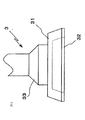
- the polycrystalline silicon block is prepared by pouring a molten raw material into a mold and cutting and removing the surface layer portion (six sides) of the cube-shaped silicon ingot with a band saw or wire saw. 4 plane portions are formed, and the two plane portions intersect at right angles to form a corner portion, and a minute plane (chamfered portion) is formed at the corner portion.
- a single crystal silicon block is obtained by cutting the surface layers of both ends of a cylindrical silicon ingot manufactured by a pulling method using a band saw or a wire saw so as to be perpendicular to the pillar axis of the silicon ingot and parallel to each other. Then, the cylindrical surface layer portion is cut and removed using a band saw or a wire saw so that each of the four surfaces forms a right angle. At this time, the four corners are processed so that a part of the cylindrical surface layer portion remains as a fine arc surface, and the cut and removed surfaces are formed as four plane portions.
- the holding mechanism of the silicon block and its rotating mechanism the holding mechanism that holds both ends (both ends in the longitudinal direction) of the silicon block, and the positions where the silicon block processed portions (each planar portion and each corner) face the processing means. It is disclosed in paragraph 0021 and FIG. 6 of Patent Document 1 that a rotation mechanism that controls the rotation of the holding mechanism is provided. Moving the silicon block in the horizontal direction (longitudinal direction of the silicon block) while polishing is disclosed in paragraph 0020 and FIG. 6 of Patent Document 1, and conversely, a grinding / polishing apparatus is used while polishing. It is also known to move in the horizontal direction (longitudinal direction of the silicon block).
- the doughnut is composed of two processes, a rough polishing process with a coarse abrasive grain and a finish polishing process with a fine abrasive grain, and the polishing jig mixes diamond abrasive grains with a resin brush. It is also well-known that it consists of the rotating brush formed in the shape.
- polishing jig is ground using a circular grindstone containing abrasive grains or a diamond wheel (polishing wheel). It is also known that high dimensional accuracy can be obtained.
- microcracks and minute irregularities generated on the surface of the silicon block when it is cut and formed from a silicon ingot are removed, and the incidence of defective products due to cracks and chips when the silicon block is formed by slicing the silicon block
- a method for processing a silicon block in which the resistance is lowered is also known.
- Patent Document 1 Japanese Patent No. 4133935
- the silicon block made of polycrystal or single crystal is formed by cutting the silicon ingot so that the cross-sectional shape is a square and a quadrangular prism, and the cross-sectional dimension is 125 mm on a side ( There are three types with a square cross-section of 5 inches), 156 mm on each side (name: 6 inches), and 210 mm on each side (name: 8 inches).
- the length in the column axis direction is any length between 150 and 600 mm. It is cut and formed.
- a method of cutting the silicon ingot there is a method using a band saw or a wire saw.
- a wire saw that cuts simultaneously with a plurality of wires has a higher cutting efficiency than a band saw.
- the loose abrasive method is used in which the wire is contacted and rotated while spraying the abrasive grains on the cutting part.
- the abrasive grains are fused and fixed to the wire for the purpose of further increasing the cutting efficiency.
- a new wire using an abrasive method has been developed, and a new cutting method using the new wire saw has been adopted.
- the time required for the conventional wire saw was 8 hours or more, but the new wire saw can be completed in about 3 hours, and it was confirmed that the cutting time can be greatly shortened.
- the reason why the cutting time can be shortened is that, in the conventional loose abrasive type wire saw, when the wire is rotated at a high speed during the cutting process, the abrasive grains are scattered and the cutting efficiency is lowered. This is probably because the abrasive grains are melted and fixed on the wire, and there is no scattering of the abrasive grains accompanying the rotation of the wire.
- the silicon block cut and formed from the silicon ingot has irregularities having a surface roughness of Ry 10 to 20 ⁇ m (JISB0601: 1994) on the surface portion of the flat portion and the corner portion, and further deeper than the surface layer surface.
- Microcracks with a length of 80 to 100 ⁇ m are generated and present during the manufacturing process. Therefore, in the subsequent process, when the silicon wafer is sliced with a wire saw and processed into a silicon wafer, cracks and chips may occur due to the unevenness and microcracks, and defective products may be generated.
- the rough polishing ability for removing microcracks existing at a depth of 80 to 100 ⁇ m from the surface layer surface is obtained by polishing and removing the surface of the silicon block to a depth of about 100 ⁇ m before slicing. Therefore, there is a demand for a processing apparatus having a fine polishing ability for making a surface having a surface roughness of about Ry 10 to 20 ⁇ m into a surface roughness of several ⁇ m or less.
- a rectangular pillar-shaped polycrystalline silicon block formed by cutting a silicon ingot or a single-crystal silicon block has a side of 125 mm (name: 5 inches), a side of 156 mm ( Nominal name: 6 inches), grinding function to grind to any cross-sectional dimension of 210 mm (nominal: 8 inches), and the surface roughness of the flat part and corner part of the silicon block is refined and formed inside the surface layer
- the silicon block grinding / polishing processing device and its grinding / polishing processing have been improved so that the polishing function that removes microcracks can be performed with a single processing device. It aims to provide a method.
- the processing apparatus for a polygonal columnar member of the present invention includes a gripping means (1) for gripping a polygonal columnar hard and brittle material as a workpiece, measurement of a cross-sectional dimension of the workpiece, and a gripping means of the gripping means (1).
- Polishing means (4) for polishing the flat portion (F) and corner portion (C) of the processed workpiece and removing microcracks existing on the surface layer, and the workpiece gripped by the gripping means (1)
- Transfer means (5) for transferring the gripping means (1) holding the workpiece to the position where the measurement means (2), grinding means (3), and polishing means (4) are arranged, and input before starting the processing.
- a control means (6) for performing arithmetic processing based on the initial setting items and the measurement signal of the measurement means (2) and outputting an operation signal to each means (first invention).
- the polygonal columnar member grinding / polishing apparatus applies a certain cut to the grinding means (3) to the work piece, such as distortion of the work piece. Grinding function that cuts the outer dimensions within tolerance while adjusting the shape, and applying a constant pressure to the polishing means (4) against the workpiece and copying along the surface of the workpiece.
- the surface layer is polished by several to several tens of ⁇ m to remove irregularities and cracks and has a polishing function to finely polish the surface roughness.
- the grinding means (3) is a rotating plate A (31) in which the surface of an abrasive grain part (32) formed by melting and fixing abrasive grains is in contact with the processing surface of the workpiece.
- the polishing means (4) is a brush bristle material (42) in which abrasive grains are melted and fixed.
- the grinding means (3) has a grinding ability that cuts out distortions of the workpiece and adjusts the shape and cuts the outer dimensions within the tolerance by using a rigid grindstone. Because it is equipped, it can be precisely ground.
- the polishing means (4) is a polishing brush having a brush bristle material (42) made of a material in which abrasive grains are melted and fixed, so that the brush bristle material (42) is applied to the processing surface of the workpiece during polishing.
- the surface layer of the workpiece is polished by several ⁇ m to several tens of ⁇ m by being pressed and rotated while following the hair tip, and the microcrack can be removed and the polishing process for finely finishing the surface can be performed accurately.
- the brush bristle material (42) When the brush bristle material (42) is consumed, the brush bristle material (42) mixed with abrasive grains is bundled into the grinding brush of the grinding means (4) so that it can be attached to and detached from the rotating disk B (41).
- the brush bristle material When the brush bristle material is consumed by fixing the brush bristle material (see FIG. 7 and the embodiment) and the brush bristle material (not shown) to the rotating disk.
- the brush bristle material There is a type (not shown) in which both the turntables are exchanged together, and either one may be used.
- the grindstone of the grinding means (3) has one or more kinds of abrasive grains fused and fixed to the abrasive grain portion (32), and the polishing brush of the polishing means (4) It is good also considering the particle size of the abrasive grain melt-fixed by a hair material (42) as 2 or more types (3rd invention).
- the polishing brush of the polishing means (4) has two or more types of abrasive grains fused and fixed to the brush bristle material (42), and the brush bristle material (42) with coarse abrasive grains is rotated.
- the brush bristle material (42) having a fine grain size of the abrasive grains is implanted in the outer ring portion far from the rotation center of the rotating disk B (41) while being implanted in the inner ring part near the rotating center of the disk B (41). (4th invention).
- the brush bristle material (42) having a coarse abrasive grain size is implanted in the inner ring portion near the rotation center of the rotating disk B (41), and the brush bristle grain size is fine.
- One polishing brush provided with two kinds of brush bristle materials (42) in which the material (42) can be implanted in an outer ring portion far from the rotation center of the rotating disk B (41) and the grain size of the abrasive grains is different. It only has to be installed, and the production cost can be reduced and the apparatus can be made compact.
- the grinding means (3) is a grindstone composed of F90 to F220 (JISR6001: 1998) and # 240 to # 500 (JISR6001: 1998), and the polishing means (4) has an abrasive grain size.
- a polishing brush for rough polishing made of # 240 to # 500 (JISR6001: 1998) and a polishing brush for fine polishing made of # 800 to # 1200 (JISR6001: 1998) may be provided (No. 1). 5 invention).
- the abrasive grain size of the grinding means (3) is selected from the F90 to F220 coarse grain classifications defined in JIS R6001: 1998 and the # 240 to # 500 precision grinding classifications. The advantages of the two groups will be described.
- the side is 125 mm ⁇ 0.5 mm
- the name is 6 inches
- the side is 156 mm ⁇ 0.5 mm
- the name is 8
- it is finished to any one dimension of 210 mm ⁇ 0.5 mm on a side, but depending on the case, it may be outside this tolerance or the cross-sectional shape of the square pillar-shaped silicon block (W) may be one. In other cases, the squareness of each corner (C) may be outside the allowable tolerance of 90 ⁇ 0.1 degrees.
- the coarseness of F90 to F220 is such that the cutting efficiency is increased and grinding can be performed in order to keep the cross-sectional dimension and cross-sectional shape within the tolerances. It is possible to prevent the occurrence of chipping and to perform the grinding process when grinding the grain division and the portion (such as the corner (C) of the polycrystalline silicon block (W)) where cracking or chipping is likely to occur. There is an advantage that the precision polishing sections # 240 to # 500 can be selected and used.
- melt-solidified abrasive grains having two types of particle sizes are applied to the abrasive grain portion (32) of the grinding means (3), for example, a circular or annular zone is applied to the ground surface of the abrasive grain portion (32).
- An inner ring region and a ring-shaped outer ring region provided outside the inner ring region are provided, and fine abrasive grains are melted and solidified in the inner ring region, and coarse abrasive particles are melted and solidified in the outer ring region.
- the inner ring region can be protruded from the outer ring region, and the protruding amount can be formed as the amount of fine abrasive grains cut.
- the abrasive grains of the polishing means (4) those having a particle size of # 240 to # 500 defined in JIS R6001: 1998 are applied to a polishing brush for rough polishing, and those of # 800 to # 1200 are finely polished.
- polishing brushes By applying two types of polishing brushes to the polishing brush for use in the process, microcracks existing in the surface layer of the silicon block (workpiece) can be removed due to the high polishing ability of the polishing brush for rough polishing. After removing efficiently and accurately, the surface roughness of the surface layer portion roughened by the rough polishing process can be finely polished by the fine polishing ability of the polishing brush for fine polishing, and cracks and chips in the subsequent process It became possible to eliminate the occurrence of.
- the measuring means (2) includes a reference block (15), measuring tools A (21) and (21), and measuring tool B (22).
- the reference block (15) is formed on both sides, has a reference surface having a known interval, and gripping means so that the column axis direction of the reference block (15) is parallel to the column axis direction of the workpiece to be processed.
- the measuring tools A (21) and (21) indicate the positions of the opposing reference surfaces of the reference block (15) and the positions of the opposing flat portions (F) or the opposing corners (C) of the workpiece.
- Measuring tool B (22) is good also as composition which measures the height position of the perpendicular direction of the upper surface side plane part (F) or upper surface side corner part (C) of the above-mentioned work piece (sixth invention).
- the workpiece is a quadrangular columnar silicon block (W)
- the gripping means (1) is provided by the measuring tool A (21) (21). Further, the position of the reference surface of the reference block (15) and the position of the plane part (F) or corner part (C) of the silicon block (W) are arranged in both directions perpendicular to the column axis direction (Y direction in FIGS. 1 and 4). ) To measure and measure the actual dimension (dimension in the Y direction in FIGS. 1 and 4) of the distance between the opposing flat portions (F) or corner portions (C) of the silicon block (W). The center position of the plane portion (F) can be measured.
- the height position in the vertical direction (Z direction in FIGS. 2 and 4) of the upper surface side plane portion (F) or the upper surface side corner portion (C) of the silicon block (W) is measured by the measuring tool B (22). By doing so, the center position of the silicon block (W) in the vertical direction (Z direction in FIGS. 2 and 4) can be measured.
- the measurement of the cross-sectional dimension of ⁇ 1> is to measure the actual dimension between the two planar portions (F) or the corner portions (C) of the silicon block (W) with the measuring tool A (21) (21).
- Storing the result in the control means (6), ⁇ 2> When the gripping means (1) grips the silicon block (W), the center position for centering the gripping position is set on the base (11) of the gripping means (1). It is the center position in the Y direction shown in FIG. 1 and FIG. 4 of the placed silicon block (W). This center position is calculated based on the measured value of the measuring tool A (21) of the measuring means (2).
- the pressing tools (12) and (12) shown in FIGS. (W) positioning is performed. Moreover, the center position of the Z direction shown in FIG. 2 and FIG. 4 is calculated based on the measured value of the measuring tool B (22) of the measuring means (2). Then, the base (11) is moved up and down to be positioned so that the calculated center position in the height direction of the silicon block (W) coincides with the center in the height direction of the gripping means (1). In this way, the silicon block (W) can be gripped so that the center positions of both end faces in the column axis direction coincide with the center positions of the clamp shafts (13) and (13).
- ⁇ 3> The following process is performed to store the position of the base point corresponding to the position where the cutting amount of the grinding means (3) and the polishing means (4) is “zero”.
- the distance between the opposing reference surfaces of the reference block (15) is the measuring means (2) shown in FIGS. Measured by the measuring tool A (21) (21) and stored in the control means (6),
- the tip of the grinding means (3) and the polishing means (4) are brought into contact with the reference surface of the reference block (15), respectively, and the contact position and the control means (6) are measured according to ⁇ 1>.
- the measurement means (2) includes a contact type in which measurement is performed by directly contacting a measurement location, and a non-contact type in which measurement is performed by emitting laser light, either of which may be used.
- control means (6) performs arithmetic processing based on the initial setting items input to the control means (6) described in the first invention and the measurement signal of the measurement means (2).
- the gripping means (1), measuring means (2), grinding means (3), polishing means (4), and transfer means (5) are controlled by the operation signal based on the result. That is, the control means (6) performs arithmetic processing in each step ⁇ 1>, ⁇ 2>, and ⁇ 3> described in the supplementary explanation regarding the operation of the measurement means (2), and stores the result. Based on the results and the cross-sectional dimensions after grinding / polishing inputted to the control means (6), the cutting amounts of the grinding means (3) and the polishing means (4) are automatically set.
- the transfer means (5) for transferring (1) is operated, and in the case of a single crystal, the holding means (1) holding the silicon block (W) so as to be the processing step described in the fourteenth invention described later. ) Is activated. Further, in the case of the single crystal silicon block (W), in the processing of the corner (C), as described in the description of “continuous rotation” of the rotation mechanism (14), the single crystal silicon block (W) ) Is continuously rotated at a rotational speed separately set in the control means (6).
- the control means (6) The tip of the grinding means (3) and the tip of the polishing means (4) are brought into contact with the reference surfaces on both sides of the reference block (15), respectively, and the base points of the tip of the grinding means (3) and the tip of the polishing means (4) are obtained.
- a function to calculate (the position of the cutting depth “zero”), The cross section of the workpiece is measured by measuring the positions of the reference planes on both sides of the reference block (15) and the two plane portions (F) or the corners (C) on both sides of the workpiece by the measuring tool A (21).
- the ability to compute dimensions The measuring tool A (21) and the measuring tool B (22) with the workpiece placed on the base (11) of the gripping means (1) and positioned on both sides by the pressing tool (12).
- a function of performing an arithmetic processing on the initial setting item input before the start of machining and a measurement signal output from the measuring means (2) and outputting an operation signal to each means of the grinding / polishing apparatus (Seventh invention).
- the frequency at which the grinding means and the base point of the tip of the polishing means (the position where the cutting depth is “zero”) according to the seventh invention is calculated will be described.
- the tip of the grinding means is brought into contact with the reference surfaces on both sides of the reference block, the cutting process is performed at the position of the cutting depth ⁇ zero '', and the grinding process is performed by setting the cutting depth.
- the setting of the cutting amount of the polishing brush in polishing processing is performed by counting the number of times the polishing brush is used for polishing processing and adjusting the cutting amount at the tip of the brush bristle material.
- control means (6) since the control means (6) is provided with each function for automating the polygonal columnar member grinding / polishing apparatus of the present invention, the plane part (F) of the workpiece can be accurately obtained.
- the corner portion (C) can be ground and polished, and labor can be saved.
- the cross section of the work piece is a quadrangle, and the cross sectional dimensions and tolerances of the square columnar work piece to be ground / polished are 125 mm ⁇ 0.5 mm per side (name: 5 inches) and 156 mm ⁇ 0 per side. .5 mm (nominal: 6 inches), one side 210 mm ⁇ 0.5 mm (nominal: 8 inches), and a straight part of the corner (C) where the two plane parts (F) of the square columnar workpiece intersect each other
- the angle may be set to 90 ⁇ 0.1 degrees as the tolerance of the cross-sectional shape (eighth invention).
- the grinding / polishing processing is performed based on the cross-sectional dimensions after grinding / polishing of the workpiece and the tolerances among the initial setting items input to the control means (6) before the machining is started. it can.
- the gripping means (1) A base (11) on which a quadrangular columnar workpiece is placed so that its column axis is horizontal and vertically movable; A workpiece column is formed at the center of the base (11) by moving forward and backward in a direction perpendicular to the column axis of the workpiece on both sides of the base (11) and pressing both sides of the workpiece. A pressing tool (12) for positioning the shaft; The clamp shafts (13) and (13) are arranged in the same direction as the column axis of the workpiece, and are disposed on both ends of the workpiece in the column axis direction.
- the clamp shafts (13) and (13) Clamp shafts (13) and (13) that are configured to hold one end of the workpiece and to grip both end faces of the workpiece positioned at the center of the base (11),
- a rotating mechanism (14) configured to intermittently or continuously rotate the clamp shafts (13) and (13) around the axis; (9th invention).
- the clamp shafts (13) and (13) have a function of gripping both end surfaces of the workpiece in the column axis direction and measuring the dimensions of the workpiece in the column axis direction and storing them in the control means (6). Yes. Therefore, the measurement means (2), the grinding means (3), and the polishing means (4) are used to measure, grind and polish the workpiece based on the dimension measurement result in the column axis direction of the workpiece. It becomes possible to control the transfer distance of the transfer means (5) that transfers to the position where each means is arranged.
- One of the clamp shafts (13) and (13) is connected to a rotation mechanism (14) so that the workpiece can be driven to rotate. And the other is the driven side clamp shaft.
- the “intermittent rotation” of the rotating mechanism (14) means that the surface of the workpiece to be processed is rotated so that the surface to be processed faces the grinding means (3) or the polishing means (4), thereby aligning the rotation direction. It is for performing. That is, the processing order is determined based on the type of silicon block (W) input to the control means (6) before the processing is started, and an operation signal is output to the rotating mechanism (14) according to the processing order.
- W type of silicon block
- the silicon block (W) is rotated by 45 degrees, and the pair of opposing corner portions (C) are processed. .
- the silicon block (W) is further rotated 90 degrees to process the remaining pair of corners (C), and the processing of all the plane portions (F) and corners (C) is completed. .
- Continuous rotation of the rotating mechanism (14) is a case where a corner (C) of a workpiece (for example, a single crystal silicon block (W)) whose processing surface has an arc shape is ground or polished. Further, the workpiece is processed while being continuously rotated.
- the clamp shaft (13) for gripping the workpiece is continuously rotated according to a rotation speed set separately.
- the clamp shafts (13) and (13) are the centers of both end surfaces of the column shaft of the workpiece.
- the workpiece can be accurately gripped at the position, and further, when the workpiece is ground or polished, as described above, the “intermittent rotation” and the “continuous rotation” can be accurately performed.
- the workpiece may be a quadrangular columnar silicon block (tenth invention).
- the method of grinding grinding
- the cross section of the workpiece is a quadrangle
- the grain size of the grindstone used in the grinding means (3) is F90 to F220 (JISR6001: 1998) and # 240 to ##. 500
- the grain size of abrasive grains used in the polishing brush for rough polishing of the polishing means (4) is # 240 to # 500 (JISR6001: 1998)
- the fine polishing of the polishing means (4) The grain size of the abrasive grains used in the polishing brush for the machine is # 800 to # 1200 (JISR6001: 1998)
- the cross-sectional dimensions and tolerances of the square columnar workpiece to be ground and polished are 125 mm ⁇ 0.5 mm on a side ( Nominal: 5 inches), one side of 156 mm ⁇ 0.5 mm (nominal: 6 inches), one side of 210 mm ⁇ 0.5 mm (nominal: 8 inches),
- the grinding allowance in the grinding means (3) is 20 ⁇ m to 700 ⁇ m, and the surface roughness of the workpiece in the grinding means (3) is Ry 2.0 to 10.0 ⁇ m ( After grinding to JISB0601: 1994), the grinding allowance in the polishing means (4) is 75 ⁇ m or more, and the surface roughness of the workpiece in the polishing means (4) is Ry1.1 ⁇ m (JISB0601: 1994) or less.
- a method for grinding and polishing a polygonal columnar member that is polished so as to be (13th invention) is also possible.
- the eleventh invention may be a grinding / polishing method for a polygonal columnar member in which the workpiece is a quadrangular columnar silicon block (fourteenth invention).
- the workpiece is a polycrystalline silicon block (W)
- the processing step of the polycrystalline silicon block (W) is performed by grinding a flat surface portion (F) and a corner portion (C ) Grinding process and the planar part (F) polishing process may be performed in this order (15th invention).
- the polishing process is performed only on the four plane portions (F), and the corner portion (C) is not polished.
- F) is almost all, and in the corner portion (C), there are microcracks in the vicinity of the joint portion with the plane portion (F). If the four plane portions (F) are polished by 75 ⁇ m or more, the corner portion ( This is because microcracks existing in the vicinity of the joint between C) and the plane portion (F) can be removed at the same time.
- the workpiece is a single crystal silicon block (W), and the processing step of the single crystal silicon block (W) is performed by grinding a flat surface portion (F) and a corner portion (C ) Grinding process, corner part (C) polishing process, and planar part (F) polishing process may be performed in this order (16th invention).
- the polishing of the corner portion (C) is performed before the polishing of the flat portion (F), as in the case of the polycrystalline silicon block (W). Even in the case of W), there are many cases where microcracks exist in the vicinity of the joint portion between the corner portion (C) and the flat portion (F), and if the flat portion (F) is polished, the microcracks are removed. Because it can.
- the silicon block (W) is, for example, 125 mm (nominal: 5 inches) on one side, 156 mm (nominal: 6 inches) on one side, 210 mm (nominal: 8 inches) on one side, and its dimensional tolerance is ⁇ 0.5 mm.
- the silicon block (W) whose cross-sectional dimensions and perpendicularity are out of the standard in the cutting process of the silicon ingot in the silicon block (W) production line is carried into the grinding / polishing apparatus of the present invention. Even if it exists, it can process so that a cross-sectional dimension and a cross-sectional shape may be settled in tolerance by using a grindstone as a grinding means (3).
- the microcracks can be removed by using a polishing brush as the polishing means (4).
- a silicon wafer is formed by slicing the silicon block (W) into a thickness of several hundred ⁇ m using a wire saw in the next step, the outer dimensions of the silicon wafer can be processed within a tolerance.
- a rotation mechanism (14) that causes the clamp shafts (13) and (13) of the gripping means (1) that grips the silicon block (W) to “intermittently rotate” or “continuously rotate” the clamp shafts (13) and (13).
- a polycrystalline silicon block (W) in which the corner (C) of the silicon block (W) has a C-plane (flat chamfered surface) shape, and an arc-shaped single-crystal silicon block (W) ) Can be ground and polished. Therefore, the processing steps for both the polycrystalline silicon block (W) and the single crystal silicon block (W) can be automated.
- the silicon block grinding / polishing apparatus of the present invention is Gripping means (1) for gripping the quadrangular columnar silicon block (W);
- the measurement of the cross-sectional dimension of the silicon block (W), the centering of the gripping means (1) where the silicon block (W) is gripped, and the cutting amounts of the grinding means (3) and the polishing means (4) are set to “zero”.
- Measuring means (2) necessary for calculating the position of the base point
- the plane part (F) and the corner part (C) of the silicon block (W) are ground to have a side of 125 mm (name: 5 inches), a side of 156 mm (name: 6 inches), and a side of 210 mm (name: 8 inches).
- Grinding means (3) for grinding to any cross-sectional dimension
- Polishing means (4) for polishing the planar portion (F) and the corner portion (C) of the silicon block (W) after the grinding process to remove microcracks existing in the surface layer
- Holding means (1) holding the silicon block (W) in order to measure, grind and polish the flat part (F) and the corner part (C) of the silicon block (W) held by the holding means (1) )
- control means (6) for performing arithmetic processing based on the initial setting items input before the start of machining and the measurement signal of the measurement means (2) and outputting an operation signal to each means.
- the initial setting item comprising the outer dimensions, the grain size of the abrasive grains (4), the rotational speed, and the transfer speed of the silicon block (W) during grinding / polishing by the transfer means (5) is controlled by the control means (6). To enter.
- the transfer speed of the silicon block (W) during grinding / polishing input to the control means (6) needs to be set in a range where no grinding or polishing trace remains, and the polycrystalline silicon block (W)
- the polycrystalline silicon block (W) When processing the flat part (F) and the corner part (C) of the metal, and the flat part (F) of the single crystal silicon block (W), it is set to 10 to 40 mm / second, and the angle of the single crystal silicon block (W) is set.
- processing the part (C) it is set to 10 mm / second or less.
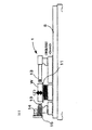
- the silicon block (W) to be machined is transferred from the carry-in conveyor (i) to the grip means (1) shown in FIG. It is installed on the base (11). Thereafter, the pressing tool (12) shown in FIGS. 1 and 3 is advanced from both sides of the silicon block (W), respectively, and the clamping axis (13) and the grinding means (3) and polishing means (4) disposed on both sides. Positioned on a line connecting the centers of the two (the center in the Y direction described in FIG. 1). In this state, one of the clamp shafts (13) is in the X direction and moves forward toward the silicon block (W) side, and the silicon block (W) is gripped by the clamp shaft (13).
- the gripping means (1) is transferred by the transfer means (5) to the position where the grinding means (3) and the polishing means (4) are arranged, and the reference block (15) placed on the gripping means (1)
- the tip of the abrasive grain part (32) of the grinding means (3) is brought into contact with the reference surfaces on both sides of the polishing means (4), and the tips of the brush bristle material (42) for rough polishing and fine polishing of the polishing means (4) are respectively connected. Make contact.
- the position of the base point at which the cutting amount of the abrasive grain portion (32) of the grinding means (3) and the brush hair material (42) for rough polishing and fine polishing of the polishing means (4) is set to “zero”. Is stored in the control means (6).
- the amount of cut refers to the surface (work surface) of the silicon block (W) as “zero (base point)”, the abrasive grains (32) of the grinding means (3) and the brush bristle material (42) of the polishing means (4). ) Indicates the amount of movement of the tip from the base point in the column axis direction. That is, the cutting allowance of the silicon block (W) is determined by the cutting amount by the grinding means (3) and the polishing means (4).
- the gripping means (1) is transferred to the position where the measuring means (2) is arranged, and as shown in FIG. 4, a pair of opposing flat portions (on both sides of the polycrystalline silicon block (W)) ( F) is measured by the measuring tool A (21), the position of the pair of plane portions (F) in the Y direction is stored in the control means (6), and the thickness of the polycrystalline silicon block (W) in the Y direction is stored. Dimensions are calculated. A grindstone in which an abrasive grain part (32) is formed on a rotating disk A (31) shown in FIGS. 5 and 6 based on the actual thickness and the “cross-sectional dimension after grinding / polishing” set in advance. The cutting amount of the grinding means (3) consisting of is automatically set.
- the gripping means (1) is transferred to the position where the grinding means (3) is disposed by the transfer means (5), and the pair of flat surfaces (F) are ground by the grinding means (3).
- the measuring tool A (21) confirms that the cross-sectional dimension is within the tolerance of the processing dimension, and then the clamp mechanism (13) of the gripping means (1) is rotated 90 degrees intermittently by the rotating mechanism (14). Then, the remaining pair of plane portions (F) is ground in the same manner as the grinding of the pair of plane portions (F), and the grinding of the four plane portions (F) is completed.
- the gripping means (1) is transferred again to the position where the measuring means (2) is disposed, and the clamp shaft (13) is intermittently rotated 45 degrees by the rotating mechanism (14), whereby the clamp shaft ( 13) A pair of opposite corners (C) of the polycrystalline silicon block (W) held by 13) face each other in the horizontal direction.
- the measurement tool A (21) measures the double-sided positions of the pair of corners (C), the actual distance between the pair of corners (C) is calculated, and the grinding means (3) The cutting depth is automatically set.
- the gripping means (1) is transferred again to the position where the grinding means (3) is arranged by the transfer means (5), the pair of corners (C) are ground, and the cross-sectional dimension is measured by the measuring tool A (21). Is within the tolerances of the machining dimensions. Thereafter, the clamp shaft (13) of the gripping means (1) is intermittently rotated 90 degrees by the rotating mechanism (14), and the remaining pair of corners (like the grinding of the pair of corners (C)) ( C) is ground, and the cross-sectional dimension of the polycrystalline silicon block (W) is ground within the tolerance of the processing dimension.
- the polycrystalline silicon block (W) that has been ground is polished by the polishing means (4) according to the following operation procedure.
- the microcracks in the surface layer of the four plane portions (F) are removed, and the cross-sectional dimension is processed within the tolerance of the processed dimension.
- a polishing brush comprising a rough polishing brush hair material (42) and a fine polishing brush hair material (42) having different abrasive grain sizes is used.
- This brush bristle material (42) is shown in FIGS.
- a method for measuring the cross-sectional dimension of the planar portion (F) to be polished a method for setting a cutting amount of a polishing brush for rough polishing and fine polishing, and polishing for rough polishing and fine polishing
- the operation procedure is the same as that of the grinding process.
- the polishing process of the polycrystalline silicon block (W) as described above, the polishing process is completed only for the four plane portions (F), and the corner portion (C) is not polished.
- the polycrystalline silicon block (W) that has finished grinding and polishing is returned to the original position together with the gripping means (1) by the transfer means (5), and is clamped by the clamp shaft (13) and the pressing tool (12). The grip state is released. Thereafter, the processed polycrystalline silicon block (W) is transferred to a carry-out conveyor (b) shown in FIG. 1 and carried out by a transfer device (not shown).
- the single crystal silicon block (W) to be ground and polished is installed on the base (11) of the gripping means (1). Both sides are gripped by the pressing tool (12) and both end surfaces are gripped by the clamp shaft (13). Since the single crystal silicon block (W) has an arc shape in which the shape of the corner portion (C) is formed leaving a part of the silicon ingot, the single crystal silicon block (W) is subjected to grinding / polishing at the corner portion (C). The silicon block (W) must be continuously rotated.
- the measuring means (2) measures the position of each side surface of the single crystal silicon block (W) with both the measuring tool A (21) in the Y direction and the measuring tool B (22) in the Z direction. Can be done. Then, the single crystal silicon block (W) can be centered based on the measurement result, and the clamp shaft (13) is aligned with the column axis of the silicon block (W) so that the clamp shaft is aligned. (13) grips the silicon block (W).
- the gripping means (1) is transferred to the position where the measuring means (2) is arranged, and the measuring tool A (21) faces each other on both sides of the single crystal silicon block (W) as shown in FIG.
- the thickness dimension in the Y direction of the pair of plane portions (F) is calculated.
- the gripping means (1) gripping the single crystal silicon block (W) to be processed measures the remaining pair of plane portions (F), and the measuring means (2) and the grinding means (3) are arranged.
- the single crystal silicon block (W) reciprocates between the formed positions, and the remaining pair of plane portions (F) is ground as well as the pair of plane portions (F). ) Is finished.
- the processing sequence during this period is the same as that of the polycrystalline silicon block (W).
- the gripping means (1) is transferred again to the position where the measuring means (2) is disposed, and the clamp shaft (13) rotates 45 degrees intermittently by the rotating mechanism (14), so that the single crystal silicon block A pair of opposite corners (C) of (W) are arranged so as to face each other in the horizontal direction.
- the both sides of the corner (C) are measured by the measuring tool A (21), and the distance between the pair of corners (C) is calculated to automatically set the cutting amount of the grinding means (3). Is done.
- the clamp shaft (13) is moved by the rotational speed of the rotating mechanism (14) set in advance.
- grinding of the corner (C) of the single crystal silicon block (W) is started.
- the clamp shaft (13) of the gripping means (1) is continuously rotated at the rotation speed of the rotation mechanism (14) set in advance, so that the four corner portions ( The rough polishing process and the fine polishing process of C) are sequentially performed.
- the clamp shaft (13) is rotated by the rotating mechanism (14), and a pair of plane portions (F) facing each other of the single crystal silicon block (W) to be polished is processed. ) Are arranged so as to face each other in the horizontal direction, and polishing is performed. Thereafter, the clamp shaft (13) is rotated by 90 degrees by the rotation mechanism (14), and the remaining pair of plane portions (F) are similarly polished, and all the polishing steps are completed.
- the silicon block (W) used here is a polycrystalline silicon block (W) and a single crystal silicon block (W) cut into a quadrangular prism shape, and four plane portions of these silicon blocks (W).
- F) and the four corners (C) are ground by the grinding means (3) of the present invention, so that the cross-sectional dimensions are within the tolerances, and then the single crystal silicon block ( The microcracks are removed by polishing the surface layer of W).
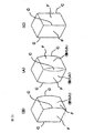
- the silicon block (W) to be processed in the first embodiment is cut out from one silicon ingot as shown in FIG.
- the silicon block (W) used in Example 1 is the silicon block A cut out from the four corners of the silicon ingot shown in FIGS. 9 and 10, and in this silicon block A, the two flat portions are swollen. Is formed.
- Tables 1 and 2 show the contents of the initial setting items input to the control means (6) before machining.
- the interval dimension (100 mm) of the reference surface of the reference block (15) is measured in advance by the measuring tool A (21) by the laser method, and the measurement result is controlled by the control means (6).
- the above-mentioned polycrystalline silicon block A is named: a cross section of 6 inches has a side of 156 mm (length: 500 mm), and the cross section of the polycrystalline silicon block A (W) is opposed to each other as shown in FIG.
- the measuring tool A (21) is used to measure a total of 18 locations including a pair of plane portions that are 3 in the height direction ⁇ 3 locations in the longitudinal direction (a total of 9 locations) and 9 locations in the remaining pair of plane portions. did.
- the dimension of one side of the cross section of the polycrystalline silicon block A was 156.9 to 157.6 mm (average: 157.1 mm), and the surface roughness was Ry 21 to 27 ⁇ m (average: 24 ⁇ m).
- the length was 499.6 mm.
- the grain size of the abrasive grains forming the abrasive grain part (32) of the grinding means (3) coarser abrasive grains were selected from Table 3, and diamond abrasive grains corresponding to the grain size of F100 (JIS R6001: 1998) were selected. .
- the width of the abrasive grain part (32) is 8 mm
- the outer dimension is ⁇ 250 mm
- the depth of cut is 0.7 mm
- the rotational speed is 2700 min ⁇ 1 (corresponding to a reference peripheral speed of grinding of 30 to 40 m / second).
- the rotating mechanism (14) After passing through the polycrystalline silicon block A (W) at a speed of 20 mm / sec through the position where the grinding means (3) is disposed to grind the pair of plane portions (F), the rotating mechanism (14)
- the clamp shaft (13) was rotated 90 degrees to grind the remaining pair of plane portions in the same manner as described above, and the grinding of the four plane portions (F) was completed.
- the clamp shaft (13) holding the polycrystalline silicon block A (W) is rotated 45 degrees by the rotation mechanism (14) to form a pair of two corners.
- the part (C) was made to oppose in the horizontal direction as a position facing the grinding means (3) on both sides.
- the remaining pair of corners (C) is ground by setting the grain size of the abrasive grains of the grinding means (3) to # 500 and rotating the clamp shaft (13) by 90 degrees by the rotating mechanism (14). Grinding was performed in the same manner as described above to finish the grinding of the four corners (C).
- the distance between 18 planes (F) of the two pairs of plane portions (F) facing each other is 156.1 to 156.6 mm (average: 156.2 mm), and two pairs of plane portions (F ) (The result calculated by measurement value / 2) was 390 to 480 ⁇ m (average: 430 ⁇ m), and the surface roughness was Ry 5 to 8 ⁇ m (average: 7 ⁇ m).
- the polycrystalline silicon block A (W) is used with a wire saw. As a result of slicing to a thickness of 200 ⁇ m, the occurrence rate of cracks and chips was 3.8%.
- a cup-type polishing brush as shown in FIG. 7 and FIG. 8 is used for the rough polishing step and the fine polishing step in the next polishing means, and the brush bristle material (42) is formed by bundling the mounting base with a metal tube.
- a segment brush that was detachably attached to the rotating disk B (41) and was replaceable when worn was used.
- diamond abrasive grains of # 240 (JIS R6001: 1998) shown in Table 4 are used as the grain size of the abrasive grains to be melt-fixed to the brush bristle material (42).
- the outer dimensions of the polishing brush are ⁇ 210 mm, the depth of cut is 0.5 mm, the rotational speed is 1300 min ⁇ 1 converted from the reference peripheral speed of polishing process of 10 to 20 m / sec, and the polycrystalline silicon block A (W) to be polished is polished. Rough polishing was performed at a transfer rate of 20 mm / second.
- polishing brush for fine polishing diamond abrasive grains of # 800 shown in Table 4 were used as the grain size of the abrasive grains melted and fixed on the brush bristle material (42).
- the outer dimensions of the polishing brush are ⁇ 270 mm, the depth of cut is 0.8 mm, the rotation speed is converted from the reference peripheral speed of polishing processing to 10 to 20 m / sec, and is set to 1300 min ⁇ 1, and the polycrystalline silicon block A (W) to be polished is transferred
- the four flat portions (F) were polished by passing between the polishing brushes for fine polishing at a transfer speed of 20 mm / second, and all the processing was completed.
- the distance between the two plane portions (F) facing each other in a total of 18 positions is 155.9 to 156.4 mm (average: 156.1 mm).
- the processing amount was 16 to 19 ⁇ m (average: 18 ⁇ m), and the surface roughness was Ry 0.9 to 1.1 ⁇ m (average: 1.0 ⁇ m).
- Table 5 summarizes the results of grinding, rough polishing, and fine polishing of the polycrystalline silicon block A (W) of Example 1 described above.
- the polycrystalline silicon block A (W) which had been completely ground and polished, was sliced with a wire saw to form a silicon wafer, and the occurrence rate of defective products due to cracks or chipping of the silicon wafer was examined.
- the occurrence rate of defective products due to cracks, chips, etc. was 3 to 4%.
- the rough polishing process and the fine polishing process are performed to make the total polishing allowance 85 ⁇ m, and the surface roughness is set to Ry average: 1.0 ⁇ m, thereby reducing the generation rate to 1.2%. We were able to.
- the silicon block (W) to be processed in the second embodiment is a single crystal silicon block (W) obtained by cutting and forming a cylindrical single crystal silicon ingot manufactured by a pulling method.
- the upper and lower end portions of the single crystal silicon ingot are cut and removed, and the length (in the direction perpendicular to the paper surface in FIG. 11) is cut into a range of 299.0 to 301.0 mm (name: 300 mm), and then shown in FIG.
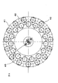
- 5 rows ⁇ 5 rows total 25 pieces were fixed vertically to the fixing jig.
- the 25 single crystal silicon ingots were cut and removed from the outer peripheral portion of the body of each single crystal silicon ingot using the new wire saw of the fixed abrasive system used in Example 1. At this time, processing was performed so that a part of the outer periphery became an arc-shaped square portion (C) having a width of about 25 mm.
- Four plane portions (F) that are substantially perpendicular to each other are simultaneously cut and formed into a single crystal silicon block (W), and one of the 25 cut single crystal silicon blocks is randomly selected. Samples were extracted and used for grinding and polishing.
- the cross section is 125 mm per side (name: 5 inches) ⁇ 300 mm in length.
- the shape of the single crystal silicon block (W) used in Example 2 is a quadrangular prism shape composed of four plane portions (F) and an arcuate corner portion (C).
- the interval dimension of the plane portions (F) is 125.4 to 126.5 mm (average: 126.1 mm)
- the length was 300.8 mm
- the surface roughness was Ry 22 to 28 ⁇ m (average: 25 ⁇ m).
- the specifications of the grinding / polishing means were the same as those in Example 1 except that the grain size of the cup-type grindstone used for the grinding means was changed to F180 selected from Table 3 (see Table 2). .
- the prepared single crystal silicon block (W) is gripped by the clamp shaft (13), and a pair of plane portions (F) are opposed to both sides in the horizontal direction. After passing through, the grinding of the two pairs of plane portions (F) was completed in the same manner as the polycrystalline silicon block (W) of Example 1.
- the clamp shaft (13) is continuously ground and rotated at a rotation speed of 105 min -1 around the axis while grinding with a pair of grindstones.
- the single crystal silicon block (W) was passed through the means (3) at a low speed of 2 mm / sec to complete the grinding of the two pairs of corners (C).
- the total distance between 18 portions of the two pairs of flat portions (F) where the flat portions (F) face each other is 124.9 to 125.8 mm (average: 125.4 mm).
- the surface roughness of the four plane portions (F) and the four corner portions (C) was Ry 4 to 6 ⁇ m (average: 5 ⁇ m).
- the next polishing process is a polishing means comprising a polishing brush for rough polishing and a polishing brush for fine polishing while continuously rotating the single crystal silicon block (W) to be polished by the rotating mechanism (14) as described above.
- the single crystal silicon block (W) was passed through the transfer means (5) at a low speed of 2 mm / sec to finish the polishing of the four corners (C).
- the polishing of the two pairs of flat portions (F) of the single crystal silicon block (W) is transferred at a rate of 20 mm / sec between the polishing means (4) by the transfer means (5) as in the first embodiment.
- the polishing of the two pairs of flat portions (F) was completed, and all the processing was completed.
- a total of 18 distances between the two plane parts (F) at which the plane part (F) facing each other at the end of the rough polishing process were measured in the same manner as described above were 124.8 to 125. 0.6 mm (average: 125.3 mm), the polishing amount was 69 to 75 ⁇ m (average: 73 ⁇ m), and the surface roughness was Ry 2.8 to 3.8 ⁇ m (average: 3.3 ⁇ m).
- the measurement result of a total of 18 intervals between the two pairs of plane portions (F) facing each other when the fine polishing process was finished was 124.7 to 125.5 mm (average: 125.2 mm).
- the processing amount was 17 to 25 ⁇ m (average: 20 ⁇ m), and the surface roughness was Ry 0.8 to 1.0 ⁇ m (average: 0.9 ⁇ m).
- the total polishing amount was set to 135 ⁇ m by rough polishing and fine polishing after grinding, and the surface roughness was set to Ry average: 0.9 ⁇ m.
- the generation rate could be reduced to 1.0%.
- the present invention has been described with respect to the invention relating to grinding / polishing of silicon blocks, but is not limited to silicon blocks, and can be suitably used for hard and brittle materials such as glass, stone, ceramics, and ferrite. It is.
Landscapes
- Engineering & Computer Science (AREA)
- Mechanical Engineering (AREA)
- Chemical & Material Sciences (AREA)
- Ceramic Engineering (AREA)
- Inorganic Chemistry (AREA)
- Mechanical Treatment Of Semiconductor (AREA)
- Finish Polishing, Edge Sharpening, And Grinding By Specific Grinding Devices (AREA)
- Grinding Of Cylindrical And Plane Surfaces (AREA)
- Grinding And Polishing Of Tertiary Curved Surfaces And Surfaces With Complex Shapes (AREA)
- Polishing Bodies And Polishing Tools (AREA)
- Constituent Portions Of Griding Lathes, Driving, Sensing And Control (AREA)
Abstract
Priority Applications (3)
| Application Number | Priority Date | Filing Date | Title |
|---|---|---|---|
| CN201180000181.2A CN102791425B (zh) | 2011-01-28 | 2011-03-08 | 多棱柱状部件的磨削/研磨加工装置以及磨削/研磨加工方法 |
| JP2011551722A JP5678898B2 (ja) | 2011-01-28 | 2011-03-08 | 多角柱状部材の研削・研磨加工装置および研削・研磨加工方法 |
| KR1020127007596A KR101616529B1 (ko) | 2011-01-28 | 2011-03-08 | 다각기둥 형상 부재의 연삭·연마 가공장치 및 연삭·연마 가공방법 |
Applications Claiming Priority (2)
| Application Number | Priority Date | Filing Date | Title |
|---|---|---|---|
| JP2011-016416 | 2011-01-28 | ||
| JP2011016416 | 2011-01-28 |
Publications (1)
| Publication Number | Publication Date |
|---|---|
| WO2012101837A1 true WO2012101837A1 (fr) | 2012-08-02 |
Family
ID=46580433
Family Applications (1)
| Application Number | Title | Priority Date | Filing Date |
|---|---|---|---|
| PCT/JP2011/055358 Ceased WO2012101837A1 (fr) | 2011-01-28 | 2011-03-08 | Dispositif de meulage/polissage pour élément en forme de colonne polygonale et procédé de meulage/polissage |
Country Status (5)
| Country | Link |
|---|---|
| JP (1) | JP5678898B2 (fr) |
| KR (1) | KR101616529B1 (fr) |
| CN (1) | CN102791425B (fr) |
| TW (1) | TWI535531B (fr) |
| WO (1) | WO2012101837A1 (fr) |
Cited By (12)
| Publication number | Priority date | Publication date | Assignee | Title |
|---|---|---|---|---|
| CN103624656A (zh) * | 2012-08-22 | 2014-03-12 | 许春雷 | 一种路缘石组合式多面打磨机 |
| CN103921358A (zh) * | 2014-03-11 | 2014-07-16 | 浙江晶盛机电股份有限公司 | 一种全自动单晶硅棒切方磨削复合加工一体设备 |
| JP5802863B2 (ja) * | 2013-04-05 | 2015-11-04 | パレス化学株式会社 | 固定砥粒ワイヤーソー用水溶性切断液及びそれを用いたインゴットの切断方法 |
| JP2016018863A (ja) * | 2014-07-07 | 2016-02-01 | 住友電気工業株式会社 | 圧粉磁心の製造方法、並びに、圧粉磁心及びコイル部品 |
| KR101621764B1 (ko) * | 2014-09-15 | 2016-05-17 | 주식회사 엔티에스 | 고체레이저용 단결정 로드 및 이의 제조방법 |
| CN106475878A (zh) * | 2016-11-25 | 2017-03-08 | 浙江晶盛机电股份有限公司 | 一种全自动单晶硅棒滚磨一体设备 |
| CN108655883A (zh) * | 2018-04-04 | 2018-10-16 | 温岭市鼎丰工量具有限公司 | 一种游标卡尺的加工机床 |
| CN108890406A (zh) * | 2018-09-19 | 2018-11-27 | 平湖凯盛大明光能科技有限公司 | 具有相互补充结构的太阳能反射镜生产工艺及加工流水线 |
| WO2019102629A1 (fr) * | 2017-11-23 | 2019-05-31 | 新東工業株式会社 | Dispositif d'usinage et procédé d'usinage d'élément de colonne polygonale |
| CN110587428A (zh) * | 2019-10-09 | 2019-12-20 | 青岛高测科技股份有限公司 | 一种半导体晶棒开Notch槽中心校准装置及方法 |
| CN113021136A (zh) * | 2021-03-09 | 2021-06-25 | 河北地质大学 | 地质勘探岩样清扫打磨装置 |
| CN113967868A (zh) * | 2020-07-24 | 2022-01-25 | 天通日进精密技术有限公司 | 硅棒研磨机和硅棒研磨方法 |
Families Citing this family (16)
| Publication number | Priority date | Publication date | Assignee | Title |
|---|---|---|---|---|
| CN103286655A (zh) * | 2013-06-18 | 2013-09-11 | 南通综艺新材料有限公司 | 一种多晶硅c角毛刷抛光机 |
| CN103639864B (zh) * | 2013-12-18 | 2015-12-30 | 天津市鹏发自动化科技有限公司 | 散热器焊缝抛光机 |
| CN103722480B (zh) * | 2013-12-30 | 2016-04-13 | 天津英利新能源有限公司 | 一种硅块抛光装置和硅块抛光方法 |
| CN103806106A (zh) * | 2014-02-25 | 2014-05-21 | 英利能源(中国)有限公司 | 单晶晶棒粘接装置 |
| CN103913417B (zh) * | 2014-03-20 | 2016-08-03 | 浙江晶盛机电股份有限公司 | 一种单晶硅棒晶向检测装置及其晶向检测方法 |
| CN104669112A (zh) * | 2015-03-04 | 2015-06-03 | 浙江理工大学 | 一种圆柱加工成正五棱柱用磨削夹具 |
| CN104816225B (zh) * | 2015-05-12 | 2017-05-03 | 新兴铸管股份有限公司 | 一种自动钢样打磨机及其使用方法 |
| CN109093516B (zh) * | 2018-09-12 | 2019-12-17 | 西门子工厂自动化工程有限公司 | 工件磨削的控制方法、控制装置、磨削工件的系统和终端 |
| CN109773614B (zh) * | 2018-12-03 | 2021-04-20 | 宁波公牛电器有限公司 | 倒角机及倒角加工方法 |
| KR102309406B1 (ko) * | 2019-11-29 | 2021-10-05 | (재)대구기계부품연구원 | 브러시 마모 자동 감지형 정밀 연마 시스템 및 이를 이용한 정밀 연마 방법 |
| CN110900427B (zh) * | 2019-12-04 | 2020-10-20 | 金上晋科技(东莞)有限公司 | 一种圆形钢管全方位抛光装置 |
| CN113021104A (zh) * | 2019-12-25 | 2021-06-25 | 东和株式会社 | 研削机构及研削装置 |
| CN113021179A (zh) * | 2019-12-25 | 2021-06-25 | 东和株式会社 | 研削机构及研削装置 |
| CN113547408A (zh) * | 2020-04-23 | 2021-10-26 | 内蒙古中环协鑫光伏材料有限公司 | 一种单晶硅方棒外圆磨削方法 |
| CN114473686B (zh) * | 2022-01-24 | 2023-12-19 | 温岭市鸿泰工量具有限公司 | 一种多功能高效率复合加工中心及其加工方法 |
| KR102674304B1 (ko) * | 2024-03-06 | 2024-06-11 | (주)탑인터네셔널 | 금형 제조용 모재를 연마하기 위한 밀링장치 |
Citations (7)
| Publication number | Priority date | Publication date | Assignee | Title |
|---|---|---|---|---|
| JPS52126594A (en) * | 1976-04-17 | 1977-10-24 | Yasuhiro Suzuki | Method of rotary grinding rectangular parallelopiped stone material |
| JPH04115873A (ja) * | 1990-08-30 | 1992-04-16 | Jason Inc | 回転仕上げ工具 |
| JP2003053664A (ja) * | 2001-08-10 | 2003-02-26 | Nagase Integrex Co Ltd | 工作機械及び加工方法 |
| JP2003159649A (ja) * | 2001-11-22 | 2003-06-03 | Denso Corp | 高精度プロファイル研削加工方法 |
| JP2003181766A (ja) * | 2001-12-17 | 2003-07-02 | Masao Nishiki | 研削工具及び研磨工具 |
| JP2004148461A (ja) * | 2002-10-31 | 2004-05-27 | Nitto Denko Corp | 端面加工方法およびその装置 |
| JP2010262955A (ja) * | 2009-04-30 | 2010-11-18 | Okamoto Machine Tool Works Ltd | シリコンインゴットの面取り加工装置およびそれを用いる角柱状シリコンインゴットの面取り加工方法 |
Family Cites Families (3)
| Publication number | Priority date | Publication date | Assignee | Title |
|---|---|---|---|---|
| US4945687A (en) * | 1989-07-25 | 1990-08-07 | Jason, Inc. | Rotary fininshing tool |
| JP4133935B2 (ja) | 2004-06-07 | 2008-08-13 | シャープ株式会社 | シリコンウエハの加工方法 |
| CN101583463B (zh) * | 2007-12-28 | 2013-03-27 | 新东工业株式会社 | 棱柱状构件的研磨装置 |
-
2011
- 2011-03-08 JP JP2011551722A patent/JP5678898B2/ja active Active
- 2011-03-08 WO PCT/JP2011/055358 patent/WO2012101837A1/fr not_active Ceased
- 2011-03-08 CN CN201180000181.2A patent/CN102791425B/zh active Active
- 2011-03-08 KR KR1020127007596A patent/KR101616529B1/ko active Active
- 2011-03-09 TW TW100107831A patent/TWI535531B/zh active
Patent Citations (7)
| Publication number | Priority date | Publication date | Assignee | Title |
|---|---|---|---|---|
| JPS52126594A (en) * | 1976-04-17 | 1977-10-24 | Yasuhiro Suzuki | Method of rotary grinding rectangular parallelopiped stone material |
| JPH04115873A (ja) * | 1990-08-30 | 1992-04-16 | Jason Inc | 回転仕上げ工具 |
| JP2003053664A (ja) * | 2001-08-10 | 2003-02-26 | Nagase Integrex Co Ltd | 工作機械及び加工方法 |
| JP2003159649A (ja) * | 2001-11-22 | 2003-06-03 | Denso Corp | 高精度プロファイル研削加工方法 |
| JP2003181766A (ja) * | 2001-12-17 | 2003-07-02 | Masao Nishiki | 研削工具及び研磨工具 |
| JP2004148461A (ja) * | 2002-10-31 | 2004-05-27 | Nitto Denko Corp | 端面加工方法およびその装置 |
| JP2010262955A (ja) * | 2009-04-30 | 2010-11-18 | Okamoto Machine Tool Works Ltd | シリコンインゴットの面取り加工装置およびそれを用いる角柱状シリコンインゴットの面取り加工方法 |
Cited By (15)
| Publication number | Priority date | Publication date | Assignee | Title |
|---|---|---|---|---|
| CN103624656A (zh) * | 2012-08-22 | 2014-03-12 | 许春雷 | 一种路缘石组合式多面打磨机 |
| JP5802863B2 (ja) * | 2013-04-05 | 2015-11-04 | パレス化学株式会社 | 固定砥粒ワイヤーソー用水溶性切断液及びそれを用いたインゴットの切断方法 |
| CN103921358A (zh) * | 2014-03-11 | 2014-07-16 | 浙江晶盛机电股份有限公司 | 一种全自动单晶硅棒切方磨削复合加工一体设备 |
| CN103921358B (zh) * | 2014-03-11 | 2015-12-30 | 浙江晶盛机电股份有限公司 | 一种全自动单晶硅棒切方磨削复合加工一体设备 |
| JP2016018863A (ja) * | 2014-07-07 | 2016-02-01 | 住友電気工業株式会社 | 圧粉磁心の製造方法、並びに、圧粉磁心及びコイル部品 |
| KR101621764B1 (ko) * | 2014-09-15 | 2016-05-17 | 주식회사 엔티에스 | 고체레이저용 단결정 로드 및 이의 제조방법 |
| CN106475878A (zh) * | 2016-11-25 | 2017-03-08 | 浙江晶盛机电股份有限公司 | 一种全自动单晶硅棒滚磨一体设备 |
| WO2019102629A1 (fr) * | 2017-11-23 | 2019-05-31 | 新東工業株式会社 | Dispositif d'usinage et procédé d'usinage d'élément de colonne polygonale |
| CN108655883A (zh) * | 2018-04-04 | 2018-10-16 | 温岭市鼎丰工量具有限公司 | 一种游标卡尺的加工机床 |
| CN108655883B (zh) * | 2018-04-04 | 2024-03-15 | 温岭市鼎丰工量具有限公司 | 一种游标卡尺的加工机床 |
| CN108890406A (zh) * | 2018-09-19 | 2018-11-27 | 平湖凯盛大明光能科技有限公司 | 具有相互补充结构的太阳能反射镜生产工艺及加工流水线 |
| CN108890406B (zh) * | 2018-09-19 | 2023-09-22 | 甘肃凯盛大明光能科技有限公司 | 具有相互补充结构的太阳能反射镜生产工艺及加工流水线 |
| CN110587428A (zh) * | 2019-10-09 | 2019-12-20 | 青岛高测科技股份有限公司 | 一种半导体晶棒开Notch槽中心校准装置及方法 |
| CN113967868A (zh) * | 2020-07-24 | 2022-01-25 | 天通日进精密技术有限公司 | 硅棒研磨机和硅棒研磨方法 |
| CN113021136A (zh) * | 2021-03-09 | 2021-06-25 | 河北地质大学 | 地质勘探岩样清扫打磨装置 |
Also Published As
| Publication number | Publication date |
|---|---|
| TW201231219A (en) | 2012-08-01 |
| TWI535531B (zh) | 2016-06-01 |
| JPWO2012101837A1 (ja) | 2014-06-30 |
| KR101616529B1 (ko) | 2016-05-11 |
| JP5678898B2 (ja) | 2015-03-04 |
| CN102791425A (zh) | 2012-11-21 |
| KR20130139736A (ko) | 2013-12-23 |
| CN102791425B (zh) | 2016-08-24 |
Similar Documents
| Publication | Publication Date | Title |
|---|---|---|
| JP5678898B2 (ja) | 多角柱状部材の研削・研磨加工装置および研削・研磨加工方法 | |
| JP5842920B2 (ja) | 硬脆性材料の研削・研磨加工システム、および研削・研磨方法 | |
| JP4816815B2 (ja) | 多角柱状部材の研磨装置およびその研磨方法 | |
| CN101972982B (zh) | 圆柱状部件的研磨装置及其研磨方法 | |
| JP5594295B2 (ja) | 円柱状部材の研磨装置および円柱状部材の研磨方法 | |
| JP7234317B2 (ja) | ツルーイング方法及び面取り装置 | |
| TWI589398B (zh) | Columnar processing equipment | |
| CN101583463A (zh) | 棱柱状构件的研磨装置 | |
| WO2019102629A1 (fr) | Dispositif d'usinage et procédé d'usinage d'élément de colonne polygonale | |
| TW201509594A (zh) | 半導體晶圓硏削裝置、半導體晶圓製造方法、及半導體晶圓硏削方法 |
Legal Events
| Date | Code | Title | Description |
|---|---|---|---|
| WWE | Wipo information: entry into national phase |
Ref document number: 201180000181.2 Country of ref document: CN |
|
| WWE | Wipo information: entry into national phase |
Ref document number: 2011551722 Country of ref document: JP |
|
| ENP | Entry into the national phase |
Ref document number: 20127007596 Country of ref document: KR Kind code of ref document: A |
|
| 121 | Ep: the epo has been informed by wipo that ep was designated in this application |
Ref document number: 11857033 Country of ref document: EP Kind code of ref document: A1 |
|
| NENP | Non-entry into the national phase |
Ref country code: DE |
|
| 122 | Ep: pct application non-entry in european phase |
Ref document number: 11857033 Country of ref document: EP Kind code of ref document: A1 |