WO2012105255A1 - Bougie d'allumage - Google Patents
Bougie d'allumage Download PDFInfo
- Publication number
- WO2012105255A1 WO2012105255A1 PCT/JP2012/000687 JP2012000687W WO2012105255A1 WO 2012105255 A1 WO2012105255 A1 WO 2012105255A1 JP 2012000687 W JP2012000687 W JP 2012000687W WO 2012105255 A1 WO2012105255 A1 WO 2012105255A1
- Authority
- WO
- WIPO (PCT)
- Prior art keywords
- spark plug
- center electrode
- rear end
- diameter
- tip
- Prior art date
- Legal status (The legal status is an assumption and is not a legal conclusion. Google has not performed a legal analysis and makes no representation as to the accuracy of the status listed.)
- Ceased
Links
Images
Classifications
-
- H—ELECTRICITY
- H01—ELECTRIC ELEMENTS
- H01T—SPARK GAPS; OVERVOLTAGE ARRESTERS USING SPARK GAPS; SPARKING PLUGS; CORONA DEVICES; GENERATING IONS TO BE INTRODUCED INTO NON-ENCLOSED GASES
- H01T13/00—Sparking plugs
- H01T13/20—Sparking plugs characterised by features of the electrodes or insulation
-
- H—ELECTRICITY
- H01—ELECTRIC ELEMENTS
- H01T—SPARK GAPS; OVERVOLTAGE ARRESTERS USING SPARK GAPS; SPARKING PLUGS; CORONA DEVICES; GENERATING IONS TO BE INTRODUCED INTO NON-ENCLOSED GASES
- H01T13/00—Sparking plugs
- H01T13/02—Details
- H01T13/04—Means providing electrical connection to sparking plugs
- H01T13/05—Means providing electrical connection to sparking plugs combined with interference suppressing or shielding means
-
- H—ELECTRICITY
- H01—ELECTRIC ELEMENTS
- H01T—SPARK GAPS; OVERVOLTAGE ARRESTERS USING SPARK GAPS; SPARKING PLUGS; CORONA DEVICES; GENERATING IONS TO BE INTRODUCED INTO NON-ENCLOSED GASES
- H01T13/00—Sparking plugs
- H01T13/20—Sparking plugs characterised by features of the electrodes or insulation
- H01T13/34—Sparking plugs characterised by features of the electrodes or insulation characterised by the mounting of electrodes in insulation, e.g. by embedding
Definitions
- the present invention relates to a spark plug used for ignition of an internal combustion engine, and more particularly to a spark plug in which a center electrode is well fixed in an axial hole of an insulator.
- a spark plug used for ignition of an internal combustion engine such as an automobile engine generally includes a cylindrical metal shell, a cylindrical insulator disposed in an inner hole of the metal shell, and a tip side of the insulator.
- a center electrode arranged in the shaft hole, a terminal fitting arranged in the other end side shaft hole, and one end joined to the front end side of the metal shell, and the other end faces the center electrode and forms a spark discharge gap.
- An electrode is arranged in the shaft hole, a terminal fitting arranged in the other end side shaft hole, and one end joined to the front end side of the metal shell, and the other end faces the center electrode and forms a spark discharge gap.
- a groove is formed on the outer periphery of the head of the center electrode.
- the spark plug is characterized by being ".
- JP 2010-267425 A Japanese Patent No. 349709
- An object of the present invention is to provide a spark plug having good adhesion between the center electrode and the sealing material.
- Means for solving the problems are as follows: (1) A shaft hole extending in the axial direction, a first inner peripheral surface extending toward the tip end side of the shaft hole, a first inner peripheral surface extending toward the rear end side of the shaft hole, and having an inner diameter larger than that of the first inner peripheral surface.
- a spark plug comprising: When the position where the center electrode starts to expand from the average outer diameter H of the leg toward the rear end from the leg is defined as a position P1, When the axial distance E from the position P1 to the tip of the center electrode is 15 mm or more, the axial distance A from the position P1 to the rear end of the center electrode is 3.8 mm or more. It is a spark plug.
- the head includes a large-diameter portion protruding in a radial direction and a protruding portion protruding from a rear end of the large-diameter portion to a rear end side.
- the inner diameter B of the cylinder S1 is smaller than the outer diameter of the large-diameter portion and is not less than 2 mm and not more than 3.3 mm.
- the spark plug according to any one of (1) to (3) assuming that a boundary between the large diameter portion and the protruding portion is a position P2 in the center electrode, the position P2 and the position The axial distance C between P1 is 0.5 mm or more and 3 mm or less.
- the axial distance A is 4 mm or more.
- an inner diameter F of the insulator at a rear end of the center electrode is 3.5 mm or less.
- the axial distance A is 4.5 mm or more.
- an inner diameter F of the insulator at a rear end of the center electrode is 2.9 mm or less.
- the axial distance A when the axial distance E is 15 mm or more, the axial distance A is 3.8 mm or more, preferably 4.5 mm or more. A good spark plug can be provided.
- the inner diameter B of the cylinder S1 is smaller than the outer diameter of the large-diameter portion, and is 2 mm or more and 3.3 mm or less, and / or the axial distance C is 0.5 mm or more and 3 mm or less. Therefore, it is possible to provide a spark plug in which the adhesion between the center electrode and the sealing material is further improved.
- the center electrode and the sealing material Particularly effective for improving adhesion.
- FIG. 1 is an entire cross-sectional explanatory view of a spark plug as an embodiment of the spark plug according to the present invention.
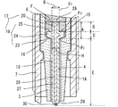
- FIG. 2 is a cross-sectional explanatory view of a main part of a spark plug which is an embodiment of the spark plug according to the present invention.
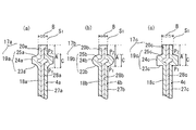
- 3 (a) to 3 (c) are cross-sectional explanatory views of the main part of the center electrode which is an embodiment of the center electrode of the spark plug according to the present invention.
- FIG. 1 shows a spark plug as an embodiment of the spark plug according to the present invention.
- FIG. 1 is an entire cross-sectional explanatory view of a spark plug 1 which is an embodiment of a spark plug according to the present invention.
- the axis of the insulator is O
- the lower side of the paper is the tip direction of the axis O
- the upper side of the paper is the rear end direction of the axis O.
- the spark plug 1 includes an insulator 3 having a shaft hole 2 extending in the direction of the axis O, a center electrode 4 held by a sealing material 6 on the front end side of the shaft hole 2, and a rear end side of the shaft hole 2.
- a ground electrode 8 arranged.
- the metal shell 7 has a substantially cylindrical shape and is formed so as to accommodate and hold the insulator 3.
- a threaded portion 9 is formed on the outer peripheral surface in the front end direction of the metal shell 7, and the spark plug 1 is attached to a cylinder head of an internal combustion engine (not shown) using the threaded portion 9.
- the metal shell 7 can be formed of a conductive steel material, for example, low carbon steel.
- the threaded portion 9 is preferably M12 or less in order to reduce the diameter.
- the ground electrode 8 is formed in, for example, a substantially prismatic body, one end is joined to the front end surface of the metal shell 7, and is bent into a substantially L shape in the middle, and the front end is connected to the front end of the center electrode 4. Its shape and structure are designed to face each other with a gap.
- the ground electrode 8 is formed of the same material as that for forming the center electrode 4.
- the terminal fitting 5 is a terminal for applying a voltage for performing a spark discharge between the center electrode 4 and the ground electrode 8 to the center electrode 4 from the outside.
- the terminal fitting 5 has an outer diameter larger than the inner diameter of the shaft hole 2, is exposed from the shaft hole 2, and has a flange portion 10 and a flange portion that are partly in contact with the end surface on the rear end side in the axis O direction of the insulator 3.
- 10 has a substantially cylindrical rod-like portion 11 that extends in the distal direction from the distal end surface in the direction of the axis O and is accommodated in the shaft hole 2.
- the terminal fitting 5 is made of, for example, low carbon steel or the like, and a Ni metal layer is formed on the surface thereof by plating or the like.
- the insulator 3 is held on the inner periphery of the metal shell 7 via a talc 12 or a packing 13.
- the insulator 3 has a first inner peripheral surface 14 extending to the tip end side of the shaft hole 2 and a second inner diameter extending to the rear end side of the shaft hole 2 and having a larger inner diameter than the first inner peripheral surface 14.
- An inner peripheral surface 15, and a shelf portion 16 that connects the first inner peripheral surface 14 and the second inner peripheral surface 15 are provided.
- the insulator 3 is fixed to the metal shell 7 with its end in the tip direction protruding from the tip surface of the metal shell 7.
- the insulator 3 is desirably a material having mechanical strength, thermal strength, electrical strength, and the like. Examples of such a material include a ceramic sintered body mainly composed of alumina.
- the center electrode 4 is supported by the shelf 16 and extends from a front end of the head 17 extending into a space surrounded by the second inner peripheral surface 15 and the first inner peripheral surface.
- 14 has a columnar leg 18 extending in a space surrounded by 14 and a distal end 29 extending from the distal end of the leg 18 and having a diameter smaller than the outer diameter of the leg 18, and the distal end is insulated.
- the metal shell 7 is insulated and held in a state of protruding from the front end surface of the body 3.
- the head portion 17 includes a large diameter portion 19 projecting in the radial direction and a projecting portion 20 projecting from the rear end to the rear end side of the large diameter portion 19.
- the tip portion 29 is exposed from the tip surface of the insulator 3 and has a truncated cone shape. In this aspect, the entire tip portion 29 is exposed from the tip surface of the insulator 3, but a part of the tip portion 29 may extend into a space surrounded by the first inner peripheral surface 14. .
- the center electrode 4 is preferably formed of a material having thermal conductivity, mechanical strength, and the like.
- the center electrode 4 is formed of a Ni-based alloy such as Inconel (trade name) 600.
- the center electrode 4 may be included in an outer layer 27 formed of a Ni-based alloy or the like, and may include an axial center portion 28 formed of a material having a higher thermal conductivity than the outer layer 27. Examples of the material to be formed include Cu, Cu alloy, Ag, or Ag alloy.
- the sealing material 6 holds the center electrode 4 in the shaft hole 2 by filling a space surrounded by the shelf portion 16, the second inner peripheral surface 15, and the head portion 17.
- the sealing material 6 can be formed by sintering seal powder containing glass powder such as sodium borosilicate glass and metal powder such as Cu and Fe.
- the resistance value of the sealing material 6 is usually several hundred m ⁇ or less.
- a resistor 21 is provided between the center electrode 4 and the terminal fitting 5 via the sealing material 6.
- the resistor 21 electrically connects the center electrode 4 and the terminal fitting 5, and the resistor 21 prevents generation of radio noise.
- the resistor 21 is made of glass powder such as sodium borosilicate glass, ceramic powder such as ZrO 2 , non-metallic conductive powder such as carbon black, and / or metal powder such as Zn, Sb, Sn, Ag, Ni, etc.
- the resistor composition can be formed by sintering.
- the resistance value of the resistor 21 is usually 100 ⁇ or more.
- a second sealing material 22 formed of the same material as the sealing material 6 is provided between the resistor 21 and the terminal metal 5, and the terminal metal 5 is sealed and fixed to the insulator 3.
- the second sealing material is provided as necessary.
- the terminal fitting 5 is sealed and fixed to the insulator 3 by the resistor 21.
- the spark plug has a position P1 at a position where the center electrode 4 starts to expand from the average outer diameter H of the leg 18 toward the rear end from the leg 18 as a position P1.
- the axial distance E from the position P1 to the tip of the center electrode 4 is 15 mm or more
- the axial distance A from the position P1 to the rear end of the center electrode 4 is 3.8 mm or more, preferably It is 4 mm or more, more preferably 4.5 mm or more.
- the spark plug is repeatedly subjected to a cooling / heating cycle, and the larger the temperature difference, the larger the thermal expansion of the head 17 and the easier formation of pores. In addition, cracks are likely to occur between the pores. Further, since vibration is generated when the internal combustion engine is operated, cracks are easily generated between the formed pores, and the gap is likely to be enlarged.
- the spark plug with the favorable adhesiveness of the center electrode 4 and the sealing material 6 can be provided. Such a spark plug prevents the center electrode 4 from loosening and rattling in the axial hole 2 of the insulator 3 even if it is provided in a combustion chamber where the temperature difference is repeated and the temperature difference is severe. Is done.
- the temperature of the head 17 differs depending on the amount of heat conducted from the tip to the head 17 even if the temperature of the tip of the center electrode 4 is the same.
- the axial distance E is short, that is, when it is less than 15 mm, the temperature of the head 17 cannot be suppressed below a certain temperature, so that the above effect cannot be obtained even if the axial distance A is increased.
- the axial distance E is long, that is, 15 mm or more, the above-mentioned effect can be obtained by setting the axial distance A to 3.8 mm or more, preferably 4 mm or more, more preferably 4.5 mm or more. It is done.
- the tip of the noble metal tip 30 is used as the tip of the center electrode 4. Therefore, when the noble metal tip 30 is provided, the axial distance E is an axial distance from the position P1 to the tip of the noble metal tip 30.
- the axial distance A is 3.8 mm or less.
- the temperature of the head 17 is likely to rise, so that the thermal expansion of the head 17 is increased, and pores and cracks are likely to occur in the sealing material 6. Therefore, the adhesion between the center electrode 4 and the sealing material 6 is poor.
- the axial distance A is long, for example, exceeding 5 mm, the position of the resistor 21 is separated from the position where the spark discharge is generated, which may reduce the effect of suppressing radio noise. Therefore, the axial distance A is preferably 5 mm or less.
- the average outer diameter H of the leg portion 18 can be measured, for example, as follows. First, with the position of 1 mm from the tip of the leg 18 in the rear end direction along the axis O as the measurement start point, the diameter of the leg 18 in two directions orthogonal to each other at the measurement start point is measured. Similarly, the average outer diameter H can be obtained by measuring the diameters in two directions at five points every 1 mm from the measurement starting point to the rear end direction and calculating the arithmetic average of the measured values at these ten points. it can.
- the position P1 is a position at which the diameter starts to be larger than the average outer diameter H from the leg portion 18 toward the rear end direction.
- the outer diameter is near the boundary between the leg portion 18 and the large diameter portion 19. This is the tip position in the direction of the axis O in a portion having an outer diameter that is always larger than the outer diameter H.
- the effect due to the axial distance A being 3.8 mm or more is particularly high.
- the average outer diameter H is 1.7 mm or more, that is, as the leg portion 18 is thicker, the heat conduction speed from the tip end of the leg portion 18 to the rear end side in the axis O direction increases, and the tip end of the raised leg portion 18 increases. This is preferable because the temperature can be lowered quickly.
- the outer diameter of the leg part 18 should just be an outer diameter which can be installed in the shaft hole 2, and the average outer diameter H is usually 5 mm or less.
- the large-diameter portion 19 has an enlarged diameter portion 23, a maximum diameter portion 24, and a reduced diameter portion 25 in order from the front end side in the axis O direction, and the rear end side of the reduced diameter portion 25.
- the projecting portion 20 is continuously provided.
- the enlarged diameter portion 23 is supported by the shelf portion 16, and the center electrode 4 is fixed in the shaft hole 2.
- the enlarged diameter portion 23 is formed in a tapered shape
- the outer peripheral surface of the maximum diameter portion 24 is formed in a columnar shape
- the reduced diameter portion 25 includes a cylindrical maximum diameter portion 24 and the maximum diameter portion 24.
- a cylindrical protrusion 20 having a smaller outer diameter is connected to form a plane orthogonal to the axis O.
- the protrusion 20 is formed in a columnar shape, and a conical recess 26 is formed at the end of the protrusion 20 opposite to the large diameter portion 19. If the recess 26 is formed, the area where the sealing material 6 and the head 17 come into contact increases, so that the sealing material 6 and the head 17 are easily in close contact with each other.
- the shape of the head 17 is not particularly limited as long as the center electrode 4 is supported by the shelf 16 and fixed in the shaft hole 2.
- various shapes are employed as shown in FIG. 3. be able to.
- FIG. 3A the shape of the head 17a on the cut surface obtained by cutting the center electrode 4a along the axis O is described in order from the front end side of the center electrode 4a with respect to the outline of the head 17a.
- the enlarged diameter portion 23a forms a curved line that is convex upward from the rear end of the leg portion 18a that forms a line parallel to the axis O, and the maximum diameter portion 24a is continuous from the rear end of this curve.
- a line segment parallel to O is formed, the reduced diameter portion 25a has a downwardly convex curve continuously from the rear end of the line segment, and the projecting portion 20a is continuously parallel to the axis O from the rear end of the curve.
- a line is made.
- the large-diameter portion 19b protrudes in a direction perpendicular to the axis O continuously from the rear end of the leg 18b that forms a line segment parallel to the axis O.
- the projecting portion 20b is continuous from the rear end of the curve and forms a line segment parallel to the axis O as in FIG.
- the enlarged diameter portion 23c forms a line segment perpendicular to the line segment from the rear end of the leg portion 18c that forms a line segment parallel to the axis O, and is the maximum.
- the diameter portion 24c forms a line segment orthogonal to the line segment and parallel to the direction of the axis O
- the reduced diameter portion 25c forms a line segment continuously inclined from the rear end of the line segment with respect to the axis O
- the protrusion 20c forms a line segment that draws a wavy line substantially parallel to the axis O continuously from the rear end of the line segment.
- the reason why the outline of the protruding portion 20c draws a wavy line is that the surface of the protruding portion 20c is processed such as threading.
- the surface of the maximum diameter portions 24a to 24c, the reduced diameter portions 25a to 25c, and the protruding portions 20a to 20c is threaded and knurled. As a result, irregularities may be formed.
- the inner diameter B of the cylinder S1 is preferably smaller than the outer diameter of the large-diameter portion 19 and not less than 2 mm and not more than 3.3 mm.
- the axial distance C between the position P2 and the position P1 that is, the axial distance C of the large diameter portion 19 is It is preferable that it is 0.5 mm or more and 3 mm or less.
- the longer the axial O-direction distance C the easier the heat is released. Accordingly, the axial distance C within the above range is suitable for reducing the thermal expansion of the large diameter portion 19.
- the axial distance C is within the above range, it is possible to provide a spark plug in which the adhesion between the center electrode 4 and the sealing material 6 is further improved.
- the axial distance C is an axial distance between the position P1 and the position P2, and the position P1 is defined as described above, and the position P2 can be defined as follows according to the shape of the center electrode 4. .
- the position P2 is a boundary between the large diameter portion 19 and the protruding portion 20, in other words, a position where the outer diameter changes in the vicinity of the boundary between the large diameter portion 19 and the protruding portion 20.
- FIGS. 2, 3 (b), and 3 (c) when the change in the outer diameter is clear, the change in the outer diameter is the largest near the boundary between the large diameter portion 19 and the protruding portion 20. Let the position be position P2.
- FIG. 2 shows that when the change in the outer diameter is clear, the change in the outer diameter is the largest near the boundary between the large diameter portion 19 and the protruding portion 20.
- a position P2 is a position where the outer diameter starts to increase from the inner diameter B of the cylinder S1 assumed as described above toward the tip of the axis O.
- the effect of the axial direction A being 3.8 mm or more is particularly high.
- the fact that the inner diameter F is 3.5 mm or less, particularly 2.9 mm or less, is due to the recent situation where development of a small spark plug is required for free engine design and miniaturization of the engine itself. desirable.
- the seal powder forming the sealing material 6 is filled in the shaft hole 2 and the pressure is applied while applying heat, as will be described later. As a result, when the center electrode 4 is sealed and fixed in the shaft hole 2, it is difficult to compress the seal material 6, so that pores are easily generated in the seal material 6. Therefore, the effect by the said axial direction distance A being 3.8 mm or more is high.
- the spark plug 1 is manufactured, for example, as follows. First, the center electrode 4, the ground electrode 8, the metal shell 7, the terminal metal fitting 5, and the insulator 3 are prepared in a predetermined shape by a known method, and one end of the ground electrode 8 is formed on the tip surface of the metal shell 7 by laser welding or the like. Join the parts.
- the center electrode 4 is inserted into the shaft hole 2 of the insulator 3, the diameter-enlarged portion 23 of the center electrode 4 is locked to the shelf portion 16 of the shaft hole 2, and the space surrounded by the first inner peripheral surface 15.
- the head portion 17 is disposed in a space surrounded by the second inner peripheral surface.
- the sealing powder forming the sealing material 6, the resistor composition forming the resistor 21, and the sealing powder forming the second sealing material 22 are put in this order from the rear end side in the shaft hole 2, and pressed.
- a pin is inserted into the shaft hole 2 and pre-compressed with a pressure of 60 N / mm 2 or more.
- the rod-shaped portion 11 of the terminal metal fitting 5 is inserted from the rear end side in the shaft hole 2, and the terminal metal fitting 5 is arranged so that the rod-shaped portion 11 contacts the seal powder.
- the sealing powder and the resistor composition are heated and heated by press-fitting until the leading end surface of the insulating member 3 comes into contact with the rear end surface of the insulator 3.
- the sealing powder and the resistor composition are sintered to form the resistor 21, the sealing material 6 and the second sealing material 22, and the center electrode 4 and the terminal fitting 5 are axially bored by the sealing material 6 and the second sealing material 22. 2 is sealed and fixed. At this time, a plurality of pores are formed in the sealing material 6 in the vicinity of the interface between the central electrode 4 and the sealing material 6 due to the difference in thermal expansion coefficient between the central electrode 4 and the sealing material 6.
- the insulator 3 to which the center electrode 4 and the terminal fitting 5 are fixed is assembled to the metal shell 7 to which the ground electrode 8 is joined.
- spark plug 1 is manufactured such that the tip of the ground electrode 8 is bent toward the center electrode 4 so that one end of the ground electrode 8 faces the tip of the center electrode 4.
- a spark plug according to the present invention is used as an ignition plug for an internal combustion engine for automobiles such as a gasoline engine, and the screw portion is provided in a screw hole provided in a head (not shown) that defines a combustion chamber of the internal combustion engine. It is screwed and fixed at a predetermined position.
- the spark plug according to the present invention can be used for any internal combustion engine, but the effect is particularly exerted in a spark plug used in an environment where the temperature in the combustion chamber is higher than before.
- the spark plug according to the present invention is not limited to the above-described embodiment, and various modifications can be made within a range in which the object of the present invention can be achieved.
- the spark plug according to the present invention can provide a spark plug having good adhesion between the center electrode and the sealing material by satisfying the above requirements regardless of the screw diameter.
- the shaft core portion 28 is exposed on the rear end surface and the rear end outer peripheral surface of the center electrode 4, but the shaft core portion 28 is exposed only on the rear end surface of the center electrode 4.
- all the shaft core portions 28 may be covered with the outer layer 27 without exposing the shaft core portion 28.
- the spark plug according to the present invention can provide a spark plug having good adhesion between the center electrode and the sealing material by satisfying the above requirements regardless of the exposed state of the shaft core portion.
- Noble metal tips 30 and 31 formed of platinum alloy, iridium alloy, or the like may be provided on the surface where the center electrode 4 and the ground electrode 8 face each other. A precious metal tip may be provided on only one of them.
- noble metal tips 30 and 31 are provided on both the center electrode 4 and the ground electrode 8, and a spark discharge gap g is formed between the noble metal tips 30 and 31. .
- a spark plug having the same shape as the spark plug shown in FIG. 1 was produced according to the above-described manufacturing process.
- An axial distance between the position P1 and the tip of the center electrode (E), an axial distance from the position P2 to the rear end of the center electrode (G), and an average outer diameter (H ) Were changed to produce spark plugs having various dimensions shown in Table 1.
- (F) was measured with a fluoroscopic image using a TOSHIBA micro CT scanner (TOSCANER).
- TOSCANER TOSHIBA micro CT scanner
- the center electrode was taken out from the spark plug and measured with a projector.
- (H) is a measurement start point at a position of 1 mm in the rear end direction along the axis from the tip of the columnar leg, and at five points every 1 mm from the measurement start point in the rear end direction. The diameter in two directions was measured and calculated.
- (B) measured the maximum diameter of the protrusion.
- test No. in Table 1 The spark plug of 12 is the same as the shape of the center electrode shown in FIG. 1 except that the surface of the protruding portion of the center electrode is threaded.
- Test No. in Table 1 The spark plug 13 was the same as the shape of the center electrode shown in FIG. 1 except that the shape of the protruding portion of the center electrode was changed to a shape processed by a three-claw chuck.
- the protrusion (B) having these shapes the protrusion was photographed with a projector from the direction orthogonal to the axis of the center electrode, and the maximum width in the radial direction of the protrusion was measured. The maximum width of the projecting portion was measured by rotation, and the maximum value among the total of six measured values measured each time the center electrode was rotated by 60 ° was defined as (B).
- the center electrode has an axial core portion made of a metal containing Cu as a main component and an outer layer made of a metal containing Ni as a main component and enclosing the axial core portion.
- the thickness was 0.4 mm.
- test no was heated with a burner so that the tip of the center electrode was 850 ° C.
- the test was conducted in the same manner as in 1-40. The results are shown in Table 2.
- the spark plugs included in the scope of the present invention have good adhesion between the center electrode and the sealing material even when the cooling cycle is repeated, and the resistance value hardly rises. It was.
Landscapes
- Spark Plugs (AREA)
- Ignition Installations For Internal Combustion Engines (AREA)
Abstract
Priority Applications (5)
| Application Number | Priority Date | Filing Date | Title |
|---|---|---|---|
| EP12742558.5A EP2672587B1 (fr) | 2011-02-02 | 2012-02-01 | Bougie d'allumage |
| KR1020137022928A KR101515314B1 (ko) | 2011-02-02 | 2012-02-01 | 스파크 플러그 |
| US13/983,073 US9124073B2 (en) | 2011-02-02 | 2012-02-01 | Spark plug |
| JP2012523529A JP5414896B2 (ja) | 2011-02-02 | 2012-02-01 | スパークプラグ |
| CN2012800075948A CN103339810A (zh) | 2011-02-02 | 2012-02-01 | 火花塞 |
Applications Claiming Priority (2)
| Application Number | Priority Date | Filing Date | Title |
|---|---|---|---|
| JP2011-020954 | 2011-02-02 | ||
| JP2011020954 | 2011-02-02 |
Publications (1)
| Publication Number | Publication Date |
|---|---|
| WO2012105255A1 true WO2012105255A1 (fr) | 2012-08-09 |
Family
ID=46602477
Family Applications (2)
| Application Number | Title | Priority Date | Filing Date |
|---|---|---|---|
| PCT/JP2012/000687 Ceased WO2012105255A1 (fr) | 2011-02-02 | 2012-02-01 | Bougie d'allumage |
| PCT/JP2012/000721 Ceased WO2012105270A1 (fr) | 2011-02-02 | 2012-02-02 | Bougie d'allumage |
Family Applications After (1)
| Application Number | Title | Priority Date | Filing Date |
|---|---|---|---|
| PCT/JP2012/000721 Ceased WO2012105270A1 (fr) | 2011-02-02 | 2012-02-02 | Bougie d'allumage |
Country Status (6)
| Country | Link |
|---|---|
| US (2) | US9124073B2 (fr) |
| EP (2) | EP2672587B1 (fr) |
| JP (2) | JP5414896B2 (fr) |
| KR (1) | KR101515314B1 (fr) |
| CN (2) | CN103339810A (fr) |
| WO (2) | WO2012105255A1 (fr) |
Cited By (11)
| Publication number | Priority date | Publication date | Assignee | Title |
|---|---|---|---|---|
| JP2014038773A (ja) * | 2012-08-17 | 2014-02-27 | Ngk Spark Plug Co Ltd | スパークプラグ |
| JP2014107128A (ja) * | 2012-11-28 | 2014-06-09 | Ngk Spark Plug Co Ltd | スパークプラグ |
| JP2015053196A (ja) * | 2013-09-09 | 2015-03-19 | 日本特殊陶業株式会社 | 点火プラグ |
| DE102014223746A1 (de) | 2014-11-20 | 2016-05-25 | Robert Bosch Gmbh | Zündkerze und Verfahren zur Herstellung einer Zündkerze |
| WO2016208118A1 (fr) * | 2015-06-22 | 2016-12-29 | 日本特殊陶業株式会社 | Bougie d'allumage |
| JP2017199455A (ja) * | 2016-04-25 | 2017-11-02 | 日本特殊陶業株式会社 | スパークプラグ |
| JP2017538269A (ja) * | 2014-12-17 | 2017-12-21 | ローベルト ボッシュ ゲゼルシャフト ミット ベシュレンクテル ハフツング | 火炎面まで達するコアを備えた点火プラグ電極を製造するための方法 |
| US10084288B2 (en) | 2015-06-22 | 2018-09-25 | Ngk Spark Plug Co., Ltd. | Spark plug |
| US10153619B2 (en) | 2015-06-22 | 2018-12-11 | Ngk Spark Plug Co., Ltd. | Spark plug |
| WO2021215051A1 (fr) * | 2020-04-20 | 2021-10-28 | 日本特殊陶業株式会社 | Bougie d'allumage |
| JP2022045383A (ja) * | 2020-09-09 | 2022-03-22 | 日本特殊陶業株式会社 | スパークプラグ |
Families Citing this family (4)
| Publication number | Priority date | Publication date | Assignee | Title |
|---|---|---|---|---|
| JP6157519B2 (ja) * | 2015-01-27 | 2017-07-05 | 日本特殊陶業株式会社 | スパークプラグ |
| JP5963908B1 (ja) * | 2015-04-28 | 2016-08-03 | 日本特殊陶業株式会社 | スパークプラグ |
| US9570889B2 (en) | 2015-07-15 | 2017-02-14 | Ngk Spark Plug Co., Ltd. | Spark plug |
| US12322931B2 (en) * | 2020-09-16 | 2025-06-03 | Niterra Co., Ltd. | Spark plug |
Citations (3)
| Publication number | Priority date | Publication date | Assignee | Title |
|---|---|---|---|---|
| JPS4844701B1 (fr) * | 1970-03-20 | 1973-12-26 | ||
| JPH02165587A (ja) * | 1988-12-20 | 1990-06-26 | Ngk Spark Plug Co Ltd | スパークプラグの中心電極 |
| JP2010267425A (ja) * | 2009-05-13 | 2010-11-25 | Ngk Spark Plug Co Ltd | スパークプラグ |
Family Cites Families (13)
| Publication number | Priority date | Publication date | Assignee | Title |
|---|---|---|---|---|
| JPS4844701A (fr) | 1971-10-09 | 1973-06-27 | ||
| JP3079383B2 (ja) * | 1990-09-29 | 2000-08-21 | 日本特殊陶業株式会社 | 内燃機関用スパークプラグ |
| JPH0844701A (ja) * | 1994-08-02 | 1996-02-16 | Hirohiko Adachi | 構造欠陥を有した化合物の電子状態予測方法 |
| JP3497009B2 (ja) | 1995-05-16 | 2004-02-16 | 日本特殊陶業株式会社 | スパークプラグ |
| JP3500555B2 (ja) | 1996-03-29 | 2004-02-23 | 日本特殊陶業株式会社 | 内燃機関用スパークプラグ |
| US6191525B1 (en) * | 1997-08-27 | 2001-02-20 | Ngk Spark Plug Co., Ltd. | Spark plug |
| JP4544597B2 (ja) * | 2000-05-01 | 2010-09-15 | 日本特殊陶業株式会社 | スパークプラグ |
| US6864622B2 (en) * | 2001-03-28 | 2005-03-08 | Ngk Spark Plug Co., Ltd. | Spark plug |
| JP3795374B2 (ja) * | 2001-10-31 | 2006-07-12 | 日本特殊陶業株式会社 | スパークプラグ |
| US20050168121A1 (en) * | 2004-02-03 | 2005-08-04 | Federal-Mogul Ignition (U.K.) Limited | Spark plug configuration having a metal noble tip |
| US7365480B2 (en) * | 2004-04-30 | 2008-04-29 | Ngk Spark Plug Co., Ltd. | Spark plug |
| JP4719191B2 (ja) * | 2007-07-17 | 2011-07-06 | 日本特殊陶業株式会社 | 内燃機関用スパークプラグ |
| CN201219174Y (zh) * | 2008-03-27 | 2009-04-08 | 张文峯 | 火星塞 |
-
2012
- 2012-02-01 KR KR1020137022928A patent/KR101515314B1/ko not_active Expired - Fee Related
- 2012-02-01 JP JP2012523529A patent/JP5414896B2/ja active Active
- 2012-02-01 EP EP12742558.5A patent/EP2672587B1/fr active Active
- 2012-02-01 US US13/983,073 patent/US9124073B2/en active Active
- 2012-02-01 WO PCT/JP2012/000687 patent/WO2012105255A1/fr not_active Ceased
- 2012-02-01 CN CN2012800075948A patent/CN103339810A/zh active Pending
- 2012-02-02 EP EP12742768.0A patent/EP2672588B1/fr active Active
- 2012-02-02 CN CN201280007532.7A patent/CN103339809B/zh active Active
- 2012-02-02 JP JP2012523532A patent/JP5414897B2/ja active Active
- 2012-02-02 WO PCT/JP2012/000721 patent/WO2012105270A1/fr not_active Ceased
- 2012-02-02 US US13/978,976 patent/US8963407B2/en active Active
Patent Citations (3)
| Publication number | Priority date | Publication date | Assignee | Title |
|---|---|---|---|---|
| JPS4844701B1 (fr) * | 1970-03-20 | 1973-12-26 | ||
| JPH02165587A (ja) * | 1988-12-20 | 1990-06-26 | Ngk Spark Plug Co Ltd | スパークプラグの中心電極 |
| JP2010267425A (ja) * | 2009-05-13 | 2010-11-25 | Ngk Spark Plug Co Ltd | スパークプラグ |
Cited By (17)
| Publication number | Priority date | Publication date | Assignee | Title |
|---|---|---|---|---|
| JP2014038773A (ja) * | 2012-08-17 | 2014-02-27 | Ngk Spark Plug Co Ltd | スパークプラグ |
| JP2014107128A (ja) * | 2012-11-28 | 2014-06-09 | Ngk Spark Plug Co Ltd | スパークプラグ |
| CN103855606A (zh) * | 2012-11-28 | 2014-06-11 | 日本特殊陶业株式会社 | 火花塞 |
| JP2015053196A (ja) * | 2013-09-09 | 2015-03-19 | 日本特殊陶業株式会社 | 点火プラグ |
| DE102014223746A1 (de) | 2014-11-20 | 2016-05-25 | Robert Bosch Gmbh | Zündkerze und Verfahren zur Herstellung einer Zündkerze |
| US9979161B2 (en) | 2014-11-20 | 2018-05-22 | Robert Bosch Gmbh | Spark plug having reduced wear of the center electrode and method of making such a spark plug |
| JP2017538269A (ja) * | 2014-12-17 | 2017-12-21 | ローベルト ボッシュ ゲゼルシャフト ミット ベシュレンクテル ハフツング | 火炎面まで達するコアを備えた点火プラグ電極を製造するための方法 |
| JP2017010741A (ja) * | 2015-06-22 | 2017-01-12 | 日本特殊陶業株式会社 | スパークプラグ |
| WO2016208118A1 (fr) * | 2015-06-22 | 2016-12-29 | 日本特殊陶業株式会社 | Bougie d'allumage |
| US10084288B2 (en) | 2015-06-22 | 2018-09-25 | Ngk Spark Plug Co., Ltd. | Spark plug |
| US10153619B2 (en) | 2015-06-22 | 2018-12-11 | Ngk Spark Plug Co., Ltd. | Spark plug |
| US10205305B2 (en) | 2015-06-22 | 2019-02-12 | Ngk Spark Plug Co., Ltd. | Spark plug |
| JP2017199455A (ja) * | 2016-04-25 | 2017-11-02 | 日本特殊陶業株式会社 | スパークプラグ |
| WO2021215051A1 (fr) * | 2020-04-20 | 2021-10-28 | 日本特殊陶業株式会社 | Bougie d'allumage |
| JP2021174581A (ja) * | 2020-04-20 | 2021-11-01 | 日本特殊陶業株式会社 | スパークプラグ |
| JP2022045383A (ja) * | 2020-09-09 | 2022-03-22 | 日本特殊陶業株式会社 | スパークプラグ |
| JP7490507B2 (ja) | 2020-09-09 | 2024-05-27 | 日本特殊陶業株式会社 | スパークプラグ |
Also Published As
| Publication number | Publication date |
|---|---|
| JP5414896B2 (ja) | 2014-02-12 |
| KR101515314B1 (ko) | 2015-04-24 |
| CN103339810A (zh) | 2013-10-02 |
| EP2672587A4 (fr) | 2014-09-03 |
| EP2672588A4 (fr) | 2016-11-02 |
| CN103339809B (zh) | 2015-07-22 |
| KR20130120531A (ko) | 2013-11-04 |
| EP2672588B1 (fr) | 2017-11-29 |
| US20130307402A1 (en) | 2013-11-21 |
| JPWO2012105270A1 (ja) | 2014-07-03 |
| WO2012105270A1 (fr) | 2012-08-09 |
| EP2672587A1 (fr) | 2013-12-11 |
| CN103339809A (zh) | 2013-10-02 |
| JP5414897B2 (ja) | 2014-02-12 |
| EP2672587B1 (fr) | 2019-12-25 |
| EP2672588A1 (fr) | 2013-12-11 |
| US20130285534A1 (en) | 2013-10-31 |
| US8963407B2 (en) | 2015-02-24 |
| JPWO2012105255A1 (ja) | 2014-07-03 |
| US9124073B2 (en) | 2015-09-01 |
Similar Documents
| Publication | Publication Date | Title |
|---|---|---|
| JP5414896B2 (ja) | スパークプラグ | |
| JP5401606B2 (ja) | スパークプラグ及びその製造方法 | |
| WO2011027500A1 (fr) | Bougie dallumage | |
| JP5393830B2 (ja) | スパークプラグ | |
| JP6158283B2 (ja) | スパークプラグ | |
| JP5449581B2 (ja) | スパークプラグ | |
| CN106716753B (zh) | 绝缘体以及火花塞 | |
| WO2012042774A1 (fr) | Bougie d'allumage | |
| JP6328093B2 (ja) | スパークプラグ | |
| JP5755310B2 (ja) | スパークプラグ | |
| JP5393881B2 (ja) | スパークプラグ | |
| JP5642129B2 (ja) | スパークプラグ | |
| JP2014056653A (ja) | スパークプラグ | |
| CN102177630B (zh) | 火花塞及其制造方法 | |
| JP6903717B2 (ja) | 点火プラグ | |
| JP6734889B2 (ja) | 点火プラグ | |
| JP5721680B2 (ja) | スパークプラグ | |
| JP6653785B2 (ja) | 点火プラグ | |
| JP6632576B2 (ja) | 点火プラグ |
Legal Events
| Date | Code | Title | Description |
|---|---|---|---|
| WWE | Wipo information: entry into national phase |
Ref document number: 2012523529 Country of ref document: JP |
|
| 121 | Ep: the epo has been informed by wipo that ep was designated in this application |
Ref document number: 12742558 Country of ref document: EP Kind code of ref document: A1 |
|
| WWE | Wipo information: entry into national phase |
Ref document number: 13983073 Country of ref document: US |
|
| NENP | Non-entry into the national phase |
Ref country code: DE |
|
| ENP | Entry into the national phase |
Ref document number: 20137022928 Country of ref document: KR Kind code of ref document: A |
|
| WWE | Wipo information: entry into national phase |
Ref document number: 2012742558 Country of ref document: EP |