WO2012105301A1 - 磁性流体シール - Google Patents
磁性流体シール Download PDFInfo
- Publication number
- WO2012105301A1 WO2012105301A1 PCT/JP2012/050697 JP2012050697W WO2012105301A1 WO 2012105301 A1 WO2012105301 A1 WO 2012105301A1 JP 2012050697 W JP2012050697 W JP 2012050697W WO 2012105301 A1 WO2012105301 A1 WO 2012105301A1
- Authority
- WO
- WIPO (PCT)
- Prior art keywords
- magnetic fluid
- magnetic
- annular
- annular member
- members
- Prior art date
- Legal status (The legal status is an assumption and is not a legal conclusion. Google has not performed a legal analysis and makes no representation as to the accuracy of the status listed.)
- Ceased
Links
Images


Classifications
-
- F—MECHANICAL ENGINEERING; LIGHTING; HEATING; WEAPONS; BLASTING
- F16—ENGINEERING ELEMENTS AND UNITS; GENERAL MEASURES FOR PRODUCING AND MAINTAINING EFFECTIVE FUNCTIONING OF MACHINES OR INSTALLATIONS; THERMAL INSULATION IN GENERAL
- F16J—PISTONS; CYLINDERS; SEALINGS
- F16J15/00—Sealings
- F16J15/44—Free-space packings
- F16J15/447—Labyrinth packings
-
- F—MECHANICAL ENGINEERING; LIGHTING; HEATING; WEAPONS; BLASTING
- F16—ENGINEERING ELEMENTS AND UNITS; GENERAL MEASURES FOR PRODUCING AND MAINTAINING EFFECTIVE FUNCTIONING OF MACHINES OR INSTALLATIONS; THERMAL INSULATION IN GENERAL
- F16J—PISTONS; CYLINDERS; SEALINGS
- F16J15/00—Sealings
- F16J15/16—Sealings between relatively-moving surfaces
- F16J15/40—Sealings between relatively-moving surfaces by means of fluid
- F16J15/43—Sealings between relatively-moving surfaces by means of fluid kept in sealing position by magnetic force
Definitions
- the present invention relates to a magnetic fluid seal that seals an annular gap between two relatively rotating members.
- a magnetic fluid seal that seals an annular gap between two relatively rotating members.
- the magnetic fluid seal has an advantage that the friction torque can be extremely reduced as compared with a seal made of rubber or resin.
- a structure for stably holding a magnetic fluid between two relatively rotating members is difficult compared to a solid material such as rubber or resin.
- An object of the present invention is to provide a magnetic fluid seal capable of exhibiting stable sealing performance by stably holding a magnetic fluid even when two members are eccentric.
- the present invention employs the following means in order to solve the above problems.
- the magnetic fluid seal of the present invention is In a magnetic fluid seal for sealing an annular gap between two relatively rotating members, An annular magnetic circuit forming member provided on one of the two members; An annular member provided on the other of the two members; A magnetic fluid that is magnetically adsorbed between opposing surfaces facing each other in the axial direction between the magnetic circuit forming member and the annular member; A magnetic fluid seal comprising: The annular member is configured by a member having flexibility that can be slidable so that a portion facing the magnetic circuit forming member follows the magnetic circuit forming member.
- the magnetic fluid is magnetically adsorbed between the opposing surfaces facing each other in the axial direction between the magnetic circuit forming member and the annular member, and the annular member has a portion facing the magnetic circuit forming member.
- a configuration that swings to follow the magnetic circuit forming member is employed. Therefore, even if the distance between the annular gaps between the two members changes due to the eccentricity of the two members or the two members move relative to each other in the axial direction, the magnetic fluid is magnetically adsorbed between the opposing surfaces. The distance can be kept constant. Therefore, the magnetic fluid is stably held (magnetic adsorption).
- At least a portion of the annular member in contact with the magnetic fluid has a structure capable of sucking and holding the magnetic fluid.
- the magnetic fluid can be held more securely, and the magnetic fluid can be supplied between the opposing surfaces even if the amount of the magnetic fluid decreases due to scattering or the like. Further, even if the material of the annular member itself is a non-magnetic material, the portion that sucks and holds the magnetic fluid exhibits a function equivalent to that of the magnetic material, so that a magnetic circuit can be stably formed.
- annular scattering prevention member for preventing scattering of the magnetic fluid is provided on the centrifugal direction side of the portion where the magnetic fluid is magnetically adsorbed.
- the centrifugal force acts on the magnetic fluid, and even if a part of the magnetic fluid moves away from the magnetic adsorption portion against the magnetic adsorption force, the magnetic fluid is scattered outside. Can be suppressed.
- One of the two members may be provided with an annular labyrinth seal forming member that forms a labyrinth seal structure on the outer side in the axial direction of the portion where the magnetic fluid is magnetically adsorbed.
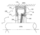
- FIG. 1 is a schematic cross-sectional view of a magnetic fluid seal according to Embodiment 1 of the present invention.
- FIG. 2 is a schematic cross-sectional view of a magnetic fluid seal according to Embodiment 1 of the present invention.
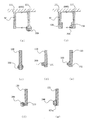
- FIG. 3 is a schematic cross-sectional view showing various modifications of the magnetic circuit forming member according to the first embodiment of the present invention.
- FIG. 4 is a schematic cross-sectional view of a magnetic fluid seal according to Embodiment 2 of the present invention.
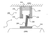
- FIG. 5 is a schematic cross-sectional view of a magnetic fluid seal according to Embodiment 3 of the present invention.
- FIG. 6 is a schematic cross-sectional view of a magnetic fluid seal according to Embodiment 4 of the present invention.
- FIG. 1 is a schematic cross-sectional view of a magnetic fluid seal according to Embodiment 1 of the present invention.
- FIG. 2 is a schematic cross-sectional view of a magnetic fluid seal according to Embodiment 1 of the present
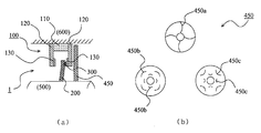
- FIG. 7A is a schematic cross-sectional view of a magnetic fluid seal according to Embodiment 5 of the present invention
- FIG. 7B is an inner wall surface view of a labyrinth seal forming member.
- FIG. 8 is a schematic cross-sectional view of a magnetic fluid seal according to Embodiment 6 of the present invention.
- FIG. 9 is a schematic cross-sectional view of a magnetic fluid seal according to Embodiment 7 of the present invention.
- FIG. 10 is a diagram showing various modifications of the magnet.
- FIG. 11 is a diagram showing various modifications of the annular member.
- FIG. 12 is a diagram showing various modifications of the annular member.
- FIG. 13 is a view showing a modification of the annular member.
- Example 1 A magnetic fluid seal according to Embodiment 1 of the present invention will be described with reference to FIGS.
- the magnetic fluid seal 1 according to the present embodiment is used in various industrial equipment such as an agitator, a VOC countermeasure gas seal, a vacuum device for semiconductor manufacturing, a fishing reel, and a shaft portion of various devices such as a bicycle. It can be applied as a leak prevention seal or dust seal.
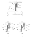
- FIG. 1 shows a state at a stationary time (when the two-member shaft 500 and the housing 600 are stationary).
- the magnetic fluid seal 1 seals an annular gap between the shaft 500 and the housing 600 that rotate relatively (including the case where one of them rotates and the other stationary).
- the magnetic fluid seal 1 includes a magnetic circuit forming member 100 attached to the inner peripheral surface of the shaft hole of the housing 600, an annular member 200 attached to the shaft 500, and a magnetic fluid 300.
- the magnetic circuit forming member 100 includes an annular permanent magnet 110 fitted to the inner peripheral surface of the shaft hole of the housing 600, and both ends (the N pole side end and the S pole side) of the permanent magnet 110. And a pair of disc-shaped magnetic pole members (pole pieces) 120 each having a hole.
- the pair of magnetic pole members 120 are provided with magnetic pole tip members 130 provided along the opposing surfaces and around the holes, respectively.
- the magnetic pole member 120 and the magnetic pole tip member 130 are both made of a magnetic material.
- a magnetic circuit M is formed that passes through the permanent magnet 110, the pair of magnetic pole members 120, the pair of magnetic pole tip members 130, and the gap between the pair of magnetic pole tip members 130.
- the annular member 200 is a disk-shaped member with a hole, and an inner peripheral surface thereof is fixed to an outer peripheral surface of the shaft 500.
- the annular member 200 is made of a flexible material so that the outer peripheral surface side can swing in the axial direction. Examples of the material include cloth such as porous silicon, rubber, resin, felt, and paper.
- the annular member 200 has a structure capable of sucking and holding the magnetic fluid 300 at least in the vicinity of the portion where the magnetic fluid 300 contacts. That is, if the above-described porous silicon, cloth, paper, or the like is employed as the material of the annular member 200, the magnetic fluid 300 can be sucked and held depending on the properties of the material itself. In addition, even if the magnetic fluid 300 cannot be sucked and held due to the properties of the material itself such as rubber or resin, by making the vicinity where the magnetic fluid 300 is in contact with a foaming structure, by capillary action, The magnetic fluid 300 can be sucked and held in the annular member 200.
- the annular member 200 is configured to face the magnetic pole tip member 130 in the magnetic circuit forming member 100 in the axial direction on the outer peripheral side thereof.
- the magnetic fluid 300 is held.
- the magnetic fluid 300 is held at least in the vicinity of the portion where the magnetic fluid 300 contacts as described above. Demonstrate. Thereby, a stable magnetic circuit is formed, and the magnetic fluid 300 is stably held.
- the annular clearance between the shaft 500 and the housing 600 is sealed by the magnetic circuit forming member 100, the annular member 200, and the magnetic fluid 300.
- the shaft 500 and the housing 600 can be eccentric when the shaft 500 and the housing 600 are relatively rotated.
- FIG. 2 shows a case where the housing 600 is moved relative to the shaft 500 in the direction of the arrow X in the drawing due to eccentricity. That is, the case where the shaft 500 and the housing 600 are relatively moved in the axial direction and the gap between the shaft 500 and the housing 600 is increased in the illustrated cross-sectional portion is shown.
- the annular member 200 follows the movement of the magnetic pole tip member 130 in the magnetic circuit forming member 100 by the magnetic adsorption force in the vicinity of the outer peripheral side thereof. Act as follows. Thereby, the state which hold
- the magnetic fluid seal 1 is configured such that the magnetic fluid 300 is magnetically adsorbed between the axially opposed surfaces between the magnetic pole tip member 130 and the annular member 200 in the magnetic circuit forming member 100. Has been. Therefore, even if the gap between the shaft 500 and the housing 600 changes, only the position where the magnetic fluid 300 contacts in the annular member 200 changes, so that the space between the opposing surfaces of the annular member 200 and the magnetic pole tip member 130 is changed. The distance of does not change.
- the annular member 200 is configured such that a portion facing the magnetic pole tip member 130 swings following the magnetic pole tip member 130. Therefore, even if the shaft 500 and the housing 600 move relative to each other in the axial direction, the distance between the facing surfaces of the annular member 200 and the magnetic pole tip member 130 hardly changes.
- the annular member 200 and the magnetic pole tip member 130 face each other.
- the distance between the faces hardly changes. Therefore, the magnetic fluid 300 is stably held (magnetically attracted) in the region between the opposed surfaces of the annular member 200 and the magnetic pole tip member 130.
- the magnetic fluid 300 can be held more reliably. Even if the amount of the magnetic fluid 300 decreases due to scattering or the like, the magnetic fluid 300 held by the annular member 200 can be supplied to the region between the opposed surfaces of the annular member 200 and the magnetic pole tip member 130. it can. For this reason, the magnetic fluid 300 can be supplied over a long period of time by holding a larger amount of the magnetic fluid 300 in the annular member 200, and the life can be extended. Even if the material of the annular member 200 is a non-magnetic material, the portion holding the magnetic fluid 300 exhibits a function equivalent to that of the magnetic material, so that the magnetic circuit M can be stably formed.
- a magnetic circuit is formed near the tip of the annular member 200 and at the position of the magnetic circuit forming member 100, and the magnetic fluid 300 can be held by the magnetic circuit. Therefore, the material of the shaft 500 may be a magnetic material or a nonmagnetic material. Further, even when the gap between the annular gaps between the shaft 500 and the housing 600 is wide, there is no need to provide a sleeve made of a magnetic material in order to form a magnetic circuit as in the prior art.
- the magnetic fluid 300 may be magnetically adsorbed in a minute gap between one of the pair of magnetic pole members 120 (the magnetic pole tip member 130) and the annular member 200. There is no need to increase the amount of 300. Further, the distance between the pair of magnetic pole members 120 (the magnetic pole tip members 130) may be widened or narrowed as long as the magnetic circuit M is formed, and the degree of freedom in design is large.
- the frictional resistance can be made extremely low by the self-lubricating action. Note that the frictional resistance can be further reduced by applying a surface treatment for reducing the frictional resistance to the surface of the annular member 200.
- the magnetic circuit forming member 100 is composed of an annular permanent magnet 110, a pair of magnetic pole members 120, and a pair of magnetic pole tip members 130 having a rectangular cross section.
- the magnetic circuit forming member applicable to the present invention is not limited to such a configuration.
- FIG. 3 is a schematic cross-sectional view showing various modifications of the magnetic circuit forming member, and shows only the cross section of the main part.
- the permanent magnets are omitted from the magnetic circuit forming members, and only one of the pair of magnetic pole members is shown.
- FIG. 3 (a) shows an example in which the magnetic circuit forming member is composed only of magnets. That is, a pair of disk-shaped permanent magnets 111 with holes are provided on the inner peripheral surface of the shaft hole of the housing 600. Of the pair of permanent magnets 111, one has an N pole on the inner peripheral side and an S pole on the outer peripheral side, and the other has an S pole on the inner peripheral side and an N pole on the outer peripheral side, thereby forming a magnetic circuit M as shown.
- the magnetic fluid 300 can be magnetically attracted to the tip of the permanent magnet 111.
- FIG. 3B shows a case where an annular magnetic pole tip member 130 is provided along the opposing surface side of the pair of permanent magnets 111 and around the hole in the configuration shown in FIG. Yes. Thereby, the magnetic fluid 300 can be concentrated only on the side facing the annular member 200 (not shown in FIG. 3).
- FIG. 3 (c) shows a case where the magnetic pole tip member 130 is not provided in the configuration shown in FIGS.
- the magnetic fluid 300 that is magnetically attracted to the tip of the magnetic pole member 120 wraps around not only on the side facing the annular member 200 (not shown in FIG. 3) but also on the opposite side. There is not so much influence on the holding function of the fluid 300.
- FIG. 3D shows a case where the magnetic pole tip member 131 has a triangular cross-sectional shape.
- FIG. 3E shows a case where the magnetic pole tip member 132 has a semi-elliptical cross section.
- FIG. 3 (f) shows a case where the magnetic pole tip member 133 having a triangular cross-sectional shape is provided adjacent to two places
- FIG. 3 (g) shows an annular member 200 (FIG. 3A) near the tip of the magnetic pole member 121.
- FIG. 3 shows a case where a plurality of triangular grooves 121a are formed on the side facing the surface (not shown).
- the cross-sectional shape of the annular member 200 is rectangular, but the shape of the annular member applicable in the present invention is limited to this. is not.
- an appropriate shape such as a triangular cross-section, an arc-shaped tip or a shape close to an ellipse can be adopted.
- the case where the magnetic pole member and the magnetic pole tip member are separate members has been shown, but a member in which these members are integrated may be employed.
- FIG. 4 shows a second embodiment of the present invention.
- a configuration in the case where an annular scattering prevention member for preventing scattering of magnetic fluid is provided will be described.
- the same components as those in the first embodiment are denoted by the same reference numerals, and the description thereof is omitted as appropriate.
- FIG. 4 is a schematic cross-sectional view of the magnetic fluid seal, and shows only a cut surface of the main part.
- annular scattering prevention member for preventing scattering of the magnetic fluid 300 is provided on the centrifugal direction side from the portion where the magnetic fluid 300 is magnetically adsorbed is shown.
- the magnetic pole member 120 is provided with an annular scattering prevention member 410.
- One end of the scattering prevention member 410 is fixed to the magnetic pole member 120, and the other end (free end) side is configured to extend toward the tip of the annular member 200.
- the structure is such that the centrifugal direction side is covered with the anti-scattering member 410 from the portion where the magnetic fluid 300 is magnetically adsorbed.
- a centrifugal force acts on the magnetic fluid 300 along with the relative rotation of the shaft 500 and the housing 600, and a part thereof is separated from the magnetic adsorption portion in the centrifugal direction against the magnetic adsorption force. Even so, the scattering prevention member 410 can suppress scattering of the magnetic fluid to the outside of the magnetic fluid seal 1. It should be noted that the magnetic fluid separated from the magnetic attracting part is in a state of being attached around the anti-scattering member 410 while the centrifugal force is acting, but when the centrifugal force stops acting, the magnetic attracting force again It can be returned to its original position.
- FIG. 4B shows a case where an annular scattering prevention member 420 is provided on the permanent magnet 110
- FIG. 4C shows an annular scattering prevention member on the annular member 200.
- the case where the member 430 is provided is shown. Even in these cases, the same effect can be obtained as in the above case.
- FIGS. 4A to 4C indicate the direction in which a part of the magnetic fluid moves away from the magnetic adsorption portion due to centrifugal force.
- the above-described scattering prevention members 410, 420, and 430 are preferably made of a non-magnetic material so that the magnetic fluid adhering to them is not magnetically attracted.
- the magnetic fluid 300 is placed in a space region formed by the scattering prevention members 410, 420, and 430 and an annular member, a magnetic pole member, or the like. It is also possible to adopt a configuration that satisfies this requirement. By adopting such a configuration, the amount of magnetic fluid 300 to be stored increases, so that the life of the magnetic fluid seal 1 can be extended.
- FIG. 4D shows a case where the space region is filled with a magnetic fluid in the example shown in FIG.
- FIG. 5 shows a third embodiment of the present invention.
- the configuration in which the magnetic fluid is held at one place by one annular member is shown.
- the magnetic fluid is held at two places by two annular members.
- the structure when doing is shown.
- the same components as those in the first embodiment are denoted by the same reference numerals, and the description thereof is omitted as appropriate.
- FIG. 5 shows a schematic cross-sectional view of the magnetic fluid seal, and shows only a cut surface of the main part.
- the configuration of the magnetic circuit forming member 100 is the same as that of the first embodiment.
- two annular members 200 are provided for the shaft 500.
- the configuration of the annular member 200 itself is the same as that in the first embodiment.
- the annular gap between the shaft 500 and the housing 600 can be sealed at two places.
- FIG. 6 shows a fourth embodiment of the present invention.
- the case where the annular member is directly fixed to the shaft is shown.
- a configuration in which the annular member is provided on the sleeve fitted to the shaft is shown.
- the same components as those in the first embodiment are denoted by the same reference numerals, and the description thereof is omitted as appropriate.
- FIG. 6 shows a schematic cross-sectional view of the magnetic fluid seal, and shows only a cut surface of the main part.
- a sleeve 210 that is fitted to the shaft 500 is provided.
- the annular member 200 is fixed to the sleeve 210.
- Other configurations are the same as those of the first embodiment.
- the sleeve 210 is provided as in this embodiment. Providing the annular member 200 is effective. That is, in this embodiment, the sleeve 210 provided with the annular member 200 can be handled as one component.
- FIG. 7 shows a fifth embodiment of the present invention.
- a configuration when a labyrinth seal structure is formed will be described.
- the same components as those in the first embodiment are denoted by the same reference numerals, and the description thereof is omitted as appropriate.
- FIG. 7 shows a schematic cross-sectional view of the magnetic fluid seal, and shows only a cut surface of the main part.
- the shaft 500 is provided with an annular labyrinth seal forming member 450 that forms a labyrinth seal structure on the outer side in the axial direction of the portion where the magnetic fluid 300 is magnetically adsorbed. It has been.
- the labyrinth seal forming member 450 is a disk-shaped member having a hole (a hole having the same diameter as the outer diameter of the shaft 500), and an inner peripheral surface thereof is fixed to the outer peripheral surface of the shaft 500.
- a minute gap is formed between the labyrinth seal forming member 450 and the magnetic pole member 120, and a labyrinth structure is formed by the minute gap.
- the pumping action is generated in the centrifugal direction by a combination of the rotation direction of the labyrinth seal forming member 450 and the shape of the protrusion or groove.
- the pumping action is generated in the centrifugal direction by a combination of the rotation direction of the labyrinth seal forming member 450 and the shape of the protrusion or groove.
- FIG. 8 shows a sixth embodiment of the present invention.
- the configuration in which the magnetic circuit forming member is provided on the housing side and the annular member is provided on the shaft side is shown.
- the magnetic circuit forming member is provided on the shaft side and the housing side
- the structure in the case of providing an annular member is shown.
- the same components as those in the first embodiment are denoted by the same reference numerals, and the description thereof is omitted as appropriate.
- FIG. 8 is a schematic cross-sectional view of the magnetic fluid seal, and shows only a cut surface of the main part.
- the magnetic circuit forming member 100 is provided on the shaft 500, and the annular member 200 is provided on the housing 600.
- the magnetic circuit forming member 100 and the annular member 200 have basically the same configuration as that described in the first embodiment, except that the inner surface side and the outer surface side are symmetrical in the radial direction. . Needless to say, this embodiment also obtains the same effects as those of the first embodiment.
- the various configurations shown in the first to fifth embodiments can be freely applied.
- the inner circumferential surface side and the outer circumferential surface side are symmetrical in the radial direction.
- the scattering prevention member shown in the second embodiment is applied to the configuration shown in the sixth embodiment, the scattering prevention member is provided on the inner peripheral surface of the shaft hole of the housing 600 or provided on the annular member 200. .
- a surface treatment may be appropriately performed so that the liquid does not enter the interface of various members.
- FIG. 9 shows a seventh embodiment of the present invention.
- the configuration in which the magnetic pole member or the magnet is arranged on both sides in the axial direction of the annular member has been shown.
- the magnet or the like is provided only on one side of the annular member in the axial direction.
- the structure in the case of arrangement is shown.
- the same components as those in the first embodiment are denoted by the same reference numerals, and the description thereof is omitted as appropriate.
- FIG. 9 shows a schematic cross-sectional view of the magnetic fluid seal, and shows only a cut surface of the main part. Further, (a) to (c) show various modifications.
- FIG. 9A shows a case where the magnetic circuit forming member 100 is constituted by only a single permanent magnet 112. That is, in this example, the outer peripheral surface of the annular permanent magnet 112 is fixed to the inner peripheral surface of the shaft hole of the housing 600. One surface of the permanent magnet 112 in the axial direction is an N pole, and the other surface is an S pole.
- the annular member 200 has the same configuration as that of the first embodiment.
- the magnetic fluid seal 1 is configured by holding the magnetic fluid 300 between the opposed surfaces of the permanent magnet 112 and the annular member 200.
- the present embodiment has a simple structure as compared with the first embodiment, can reduce the number of parts, and can be easily assembled.
- FIG. 9B is a modification of the magnetic fluid seal 1 shown in FIG.
- the magnetic circuit forming member 100 includes a permanent magnet 112 and a holding member 122 made of a magnetic material that holds the permanent magnet 112. That is, the annular groove 122g is provided in the disc-shaped holding member 122 with a hole, and the annular permanent magnet 112 is fitted and held in the annular groove 122g.
- One surface of the permanent magnet 112 in the axial direction is an N pole, and the other surface is an S pole.
- the holding region of the magnetic fluid 300 can be narrowed, and the amount of the magnetic fluid 300 can be reduced. It becomes possible.
- FIG. 9 (c) is a modification of the magnetic fluid seal 1 shown in FIG. 9 (a).
- the magnetic circuit forming member 100 includes a permanent magnet 112 and a pair of magnetic pole members 122 a and 122 b provided at both ends of the permanent magnet 112 in the axial direction.
- One surface of the permanent magnet 112 in the axial direction is an N pole, and the other surface is an S pole.
- the magnetic fluid 300 can be held in the minute gap by forming a minute gap between the inner peripheral end portions of the pair of magnetic pole members 122a and 122b.
- the holding region of the magnetic fluid 300 can be narrowed, and the amount of the magnetic fluid 300 can be reduced. It becomes possible.
- the housing 600 to which the permanent magnet 112, the holding member 122, and the magnetic pole members 122a and 122b are fixed is made of a non-magnetic material so that the magnetic force is concentrated as much as possible in the portion that holds the magnetic fluid 300. Is desirable.
- an annular sleeve made of a nonmagnetic material may be disposed on the inner periphery of the shaft hole of the housing 600, and the permanent magnet 112 or the like may be fixed to the inner periphery of the sleeve. .
- various configurations of the anti-scattering member shown in Embodiment 2 and a configuration in which the labyrinth seal forming member shown in Embodiment 5 is provided can be employed as appropriate.
- a configuration in which the magnetic circuit forming member 100 is provided on the shaft 500 and the annular member 200 is provided on the housing 600 may be employed. In this case, it is desirable that the shaft 500 be made of a nonmagnetic material.
- the permanent magnets that can be employed in the embodiments are not limited to such permanent magnets.
- an example of a magnet that can be employed in each embodiment will be described with reference to FIG.
- a magnet 113 shown in FIG. 10 (a) is composed of a plurality of disk-shaped permanent magnets 113a and a holding member 113b made of a nonmagnetic material that holds the plurality of permanent magnets 113a.
- the holding member 113b is a disk-like member having a hole, and a plurality of circular holes 113b1 are provided to hold the permanent magnet 113a.
- a permanent magnet 113a is fitted and held in each of the plurality of holes 113b1. Note that the disk-shaped permanent magnet 113a is held by the holding member 113b so that one surface has an N pole and the other surface has an S pole, and the same pole faces the same surface. However, a configuration in which N poles and S poles are alternately arranged on one surface side may be adopted.
- the magnet 114 shown in FIG. 10 (b) is a ring-shaped magnet as a whole by combining a fan-shaped permanent magnet 114a.
- the fan-shaped permanent magnets 114a are combined such that one surface is an N pole, the other surface is an S pole, and the same pole faces the same surface.
- N poles and S poles are alternately arranged on one surface side may be adopted.
- a magnet 115 shown in FIG. 10 (c) has an annular permanent magnet 115a having one surface having an N pole and the other surface having an S pole. A combination of a plurality of poles arranged alternately.
- a magnet 116 shown in FIG. 10 (d) has a substantially rod-shaped permanent magnet 116a in which one surface is an N pole and the other surface is an S pole, and an N pole and an S pole are alternately arranged on one surface side.
- An annular magnet as a whole is configured by combining a plurality of them in line.
- FIG. 10E is a cross-sectional view of the magnet 115 shown in FIG. 10C, and shows a state where the magnetic fluid 300 is held.
- a magnet 118 shown in FIG. 10 (f) is a modification of the magnet 118 shown in FIGS. 10 (c) and 10 (e), and is an example in which part of the magnet 118 has a two-layer structure. That is, only a part has a two-layer structure, and the part holding the magnetic fluid 300 can be narrowed by holding the magnetic fluid 300 in the part.
- the annular member used in each of the above embodiments may be a disc-like member having a hole and having flexibility so that it can swing in the axial direction. Therefore, for example, a single-layer structure made of a single nonmagnetic material can be adopted, but the annular member that can be adopted in each embodiment is not limited to such an annular member.
- an example of an annular member that can be employed in each embodiment will be described with reference to FIGS.
- the annular member is preferably made of a magnetic material because it constitutes a part of the magnetic circuit.
- the annular member needs to be flexible, and a single member having both magnetism and flexibility. I can't find any materials. Therefore, in order to combine magnetism and flexibility, it is possible to adopt a configuration in which a magnetic material such as filler or wire is included in a flexible material such as cloth, paper such as porous silicon, rubber, resin, or felt. it can.
- FIG. 11 shows such an example.
- FIG. 11 shows various examples of an annular member in which a disk-shaped member having a hole is used as a base material and a magnetic material is arranged inside the base material.
- the said base material is comprised from the nonmagnetic material which has a softness
- FIG. 11A shows an annular member 211 in which a plurality of rod-like magnetic bodies N are arranged along the circumferential direction inside the base material.
- FIG. 11B shows an annular member 212 in which a plurality of disk-like magnetic bodies N are arranged along the circumferential direction inside the base material.
- FIG. 11C shows an annular member 213 in which a plurality of rod-like magnetic bodies N are radially arranged inside the base material.
- FIG. 11A shows an annular member 211 in which a plurality of rod-like magnetic bodies N are arranged along the circumferential direction inside the base material.
- FIG. 11B shows an annular member 212 in which a plurality of disk-like magnetic bodies N are arranged
- FIG. 11D shows an annular member 214 in which a plurality of annular magnetic bodies N are arranged concentrically inside the substrate.
- FIG. 11E shows an annular member 215 configured such that the portions where the magnetic body N is disposed and the portions where the magnetic body N is not disposed are arranged in a lattice pattern inside the base material.
- FIG.11 (f) is the figure which showed the XX cross section in FIG.11 (c).
- the method for disposing the magnetic body N inside the base material is not particularly limited.
- the substrate is a cloth
- the magnetic material N can be arranged inside the substrate by weaving the magnetic material N.
- FIG. 11G shows an annular member 216 arranged in a state where the powdered magnetic body N is dispersed inside the base material by kneading the powdered magnetic body N into the base material.
- these annular members have both magnetism and flexibility.
- the magnetic characteristics are improved, the holding force of the magnetic fluid can be increased, and the sealing performance can be improved.
- the balance between magnetism and flexibility can be adjusted by adjusting the amount and arrangement of the magnetic material.
- the size of the magnetic body N is not particularly limited, but is preferably larger than the magnetic particles in the magnetic fluid 300.
- An annular member 217 shown in FIG. 12A includes a capillary portion 217a that causes a capillary phenomenon, and a hollow portion 217b that is connected to the capillary portion 217a.
- the annular member 217 is made of a material (rubber or resin) that cannot suck and hold the magnetic fluid 300.
- the magnetic fluid 300 can be supplied between the annular member 217 and the magnetic pole member or the like for a long period of time by storing the magnetic fluid 300 in the hollow portion 217b. , Can extend the life.
- An annular member 218 shown in FIG. 12B includes a first layer 218a having a capillary section that causes capillary action, a second layer 218b capable of sucking and holding magnetic fluid due to the properties of the material itself, and a third layer 218c. It is comprised by the multilayer structure which consists of.
- the first layer 218a and the third layer 218c are made of a material that cannot suck and hold the magnetic fluid 300.
- the magnetic fluid 300 is supplied between the annular member 218 and the magnetic pole member or the like for a long period of time by holding the magnetic fluid 300 in the second layer 218b. Can extend the service life.
- An annular member 219 shown in FIG. 12C includes a first layer 219a having a capillary section that causes a capillary phenomenon, a second layer 219b capable of sucking and holding magnetic fluid due to the properties of the material itself, and a hollow portion.
- the third layer 219c has a multilayer structure.
- the first layer 219a and the third layer 219c are made of a material that cannot suck and hold the magnetic fluid 300.
- the magnetic fluid 300 is retained in the second layer 218b and the magnetic fluid 300 is stored in the hollow portion of the third layer 219c, so that the magnetic fluid 300 is maintained over a long period of time. Can be supplied between the annular member 219 and the magnetic pole member or the like, and the life can be extended.
- the magnetic fluid seal 1 shown in FIG. 13A shows an example in which only the configuration of the annular member 220 is changed in the configuration shown in the first embodiment. That is, the annular member 200 in the first embodiment is a disc-shaped (flat plate) member with a hole, whereas the annular member 220 in this modification is configured in a bellows shape instead of a flat plate shape. This is different from the annular member 200 in the first embodiment.
- the axial portion of the shaft 500 relative to the housing 600 moves the fixed portion of the annular member 200 to the surface opposite to the surface holding the magnetic fluid 300 in the magnetic pole member 120. If this happens, the outer peripheral end of the annular member 200 may move away from the magnetic pole member 120 (see FIG. 13B). For this reason, it is difficult to stably hold the magnetic fluid 300.
- the annular member 220 when the annular member 220 has a bellows shape, the outer peripheral side can be flexibly deformed in the axial direction with respect to the inner peripheral side. Therefore, even if the fixed portion of the annular member 220 moves as described above, the magnetic pole member 120 (the magnetic pole The positional relationship of the outer peripheral side end portion of the annular member 220 with respect to the tip member 130) does not change so much (see FIG. 13C). Accordingly, it is possible to stably hold the magnetic fluid. In addition, if the annular member 220 is configured in a bellows shape, the magnetic fluid can be stably held even against a large eccentricity because it easily expands and contracts in the radial direction.
- the magnetic fluid 300 can be stably held because the outer peripheral end of the annular member 220 is deformed so as to contract even if it hits the inner peripheral surface of the permanent magnet 110. Moreover, by making the annular member 220 into a bellows shape, the magnetic fluid can be held at a plurality of locations, and the sealing performance can be further enhanced.
- the annular member is not accordion-shaped, but, for example, as shown in FIG. 13 (d), the same effect can be obtained even if an annular member 220a configured to be stepped when viewed in cross section is employed. An effect can be obtained.
- the inner peripheral side of the annular member 220a may be fixed to the outside of the magnetic pole member 120 or the like, or may be fixed to the inside.
Landscapes
- Engineering & Computer Science (AREA)
- General Engineering & Computer Science (AREA)
- Mechanical Engineering (AREA)
- Sealing Using Fluids, Sealing Without Contact, And Removal Of Oil (AREA)
Abstract
Description
相対的に回転する2部材間の環状隙間を封止する磁性流体シールにおいて、
前記2部材のうちの一方に設けられる環状の磁気回路形成部材と、
前記2部材のうちの他方に設けられる環状部材と、
前記磁気回路形成部材と前記環状部材との間の軸方向に対向する対向面間に磁気吸着される磁性流体と、
を備える磁性流体シールであって、
前記環状部材は、前記磁気回路形成部材に対向する部位が、該磁気回路形成部材に追随するように搖動可能な柔軟性を有する部材で構成されることを特徴とする。
図1~図3を参照して、本発明の実施例1に係る磁性流体シールについて説明する。なお、本実施例に係る磁性流体シール1は、攪拌機,VOC対策ガスシール,半導体製造のための真空装置などの各種産業機器や、釣り用のリールや、自転車など各種装置における軸部において、液漏れ防止用シールやダストシールとして適用可能である。
特に、図1を参照して、本発明の実施例1に係る磁性流体シールの全体構成について説明する。図1は静止時(2部材である軸500とハウジング600が静止している時)の状態を示している。
特に、図2を参照して、本発明の実施例1に係る磁性流体シール1の使用時の状態について説明する。
本実施例に係る磁性流体シール1によれば、軸500とハウジング600とが偏心等によって相対的に移動しても、磁性流体300が安定的に保持される。この点について、より詳細に説明する。
上記の説明においては、図1及び図2に示すように、磁気回路形成部材100が、環状の永久磁石110と、一対の磁極部材120と、断面矩形状の一対の磁極先端部材130とから構成される場合を示したが、本発明に適用可能な磁気回路形成部材はそのような構成に限定されることはない。本発明に適用可能な磁気回路形成部材の他の例を、図3を参照して説明する。図3は磁気回路形成部材の各種変形例を示す模式的断面図であり、主要部の断面のみを示している。なお、図3(c)~(g)においては、磁気回路形成部材のうち永久磁石については省略し、かつ一対の磁極部材のうちの一方のみを示している。
図4には、本発明の実施例2が示されている。本実施例においては、上記実施例1に示す構成に加えて、磁性流体の飛散を防止する環状の飛散防止部材を備えた場合の構成について説明する。実施例1と同一の構成部分については同一の符号を付して、その説明は適宜省略する。なお、図4は、磁性流体シールの模式的断面図を示しており、主要部について切断した切断面のみを示している。
図5には、本発明の実施例3が示されている。上記実施例1においては、一つの環状部材により、1か所で磁性流体を保持する場合の構成を示したが、本実施例においては、2つの環状部材により、2か所で磁性流体を保持する場合の構成を示す。実施例1と同一の構成部分については同一の符号を付して、その説明は適宜省略する。なお、図5は、磁性流体シールの模式的断面図を示しており、主要部について切断した切断面のみを示している。
図6には、本発明の実施例4が示されている。上記実施例1においては、環状部材が軸に直接固定される場合を示したが、本実施例においては、軸に嵌合するスリーブに環状部材を設ける場合の構成を示す。実施例1と同一の構成部分については同一の符号を付して、その説明は適宜省略する。なお、図6は、磁性流体シールの模式的断面図を示しており、主要部について切断した切断面のみを示している。
図7には、本発明の実施例5が示されている。本実施例においては、上記実施例1に示す構成に加えて、ラビリンスシール構造を形成する場合の構成について説明する。実施例1と同一の構成部分については同一の符号を付して、その説明は適宜省略する。なお、図7は、磁性流体シールの模式的断面図を示しており、主要部について切断した切断面のみを示している。
図8には、本発明の実施例6が示されている。上記各実施例においては、ハウジング側に磁気回路形成部材を設け、軸側に環状部材を設ける場合の構成を示したが、本実施例においては、軸側に磁気回路形成部材を設け、ハウジング側に環状部材を設ける場合の構成を示す。実施例1と同一の構成部分については同一の符号を付して、その説明は適宜省略する。なお、図8は、磁性流体シールの模式的断面図を示しており、主要部について切断した切断面のみを示している。
上記実施例1の図3で示した磁気回路形成部材の各種構成、実施例2で示した飛散防止部材の各種構成、実施例3で示した環状部材を2つ設ける構成、実施例4で示したスリーブを設ける構成、実施例5で示したラビリンスシール形成部材を設ける構成については、これらの中から自由な組み合わせが可能である。
図9には、本発明の実施例7が示されている。上記各実施例においては、環状部材における軸方向の両側にそれぞれ磁極部材又は磁石が配置される場合の構成を示したが、本実施例においては、環状部材における軸方向の片側にのみ磁石等が配置される場合の構成を示す。実施例1と同一の構成部分については同一の符号を付して、その説明は適宜省略する。なお、図9は、磁性流体シールの模式的断面図を示しており、主要部について切断した切断面のみを示している。また、(a)~(c)には各種変形例を示している。
上記各実施例に用いられる永久磁石としては、軸方向の一方の面がN極で、他方の面がS極で構成される、単一の環状の永久磁石を採用することができるが、各実施例で採用可能な永久磁石はそのような永久磁石に限定されることはない。ここでは、各実施例において採用可能な磁石の一例を、図10を参照して説明する。
上記各実施例に用いられる環状部材としては、孔の空いた円板状の部材であって、軸方向に搖動できるように柔軟性を有するものであればよい。従って、例えば、単一の非磁性材料からなる1層構造のものを採用することもできるが、各実施例で採用可能な環状部材はそのような環状部材に限定されることはない。ここでは、各実施例において採用可能な環状部材の一例を、図11~図13を参照して説明する。
100 磁気回路形成部材
110,111,112,113a,114a,115a,116a,117a 永久磁石
113,114,115,116,117,118 磁石
120,121,122a,122b 磁極部材
121a 溝
122 保持部材
122g 環状溝
130,131,132,133 磁極先端部材
200 環状部材
210 スリーブ
211,212,213,214,215,216,217,218,219 環状部材
217a 毛細管部
217b 中空部
218a 第1層
218b 第2層
218c 第3層
219a 第1層
219b 第2層
219c 第3層
220,220a 環状部材
300 磁性流体
410,420,430 飛散防止部材
450 ラビリンスシール形成部材
500 軸
600 ハウジング
M 磁気回路
N 磁性体
Claims (4)
- 相対的に回転する2部材間の環状隙間を封止する磁性流体シールにおいて、
前記2部材のうちの一方に設けられる環状の磁気回路形成部材と、
前記2部材のうちの他方に設けられる環状部材と、
前記磁気回路形成部材と前記環状部材との間の軸方向に対向する対向面間に磁気吸着される磁性流体と、
を備える磁性流体シールであって、
前記環状部材は、前記磁気回路形成部材に対向する部位が、該磁気回路形成部材に追随するように搖動可能な柔軟性を有する部材で構成されることを特徴とする磁性流体シール。 - 前記環状部材のうち少なくとも前記磁性流体が接触する部位は、該磁性流体を吸い込んで保持可能な構造であることを特徴とする請求項1に記載の磁性流体シール。
- 前記磁性流体が磁気吸着されている部位よりも遠心方向側には、磁性流体の飛散を防止する環状の飛散防止部材が設けられていることを特徴とする請求項1または2に記載の磁性流体シール。
- 前記2部材のうちのいずれかに、前記磁性流体が磁気吸着されている部位の軸方向外側にラビリンスシール構造を形成する環状のラビリンスシール形成部材が設けられていることを特徴とする請求項1,2または3に記載の磁性流体シール。
Priority Applications (5)
| Application Number | Priority Date | Filing Date | Title |
|---|---|---|---|
| EP12742104.8A EP2672152B1 (en) | 2011-02-03 | 2012-01-16 | Magnetic fluid seal |
| CN201280004875.8A CN103314241B (zh) | 2011-02-03 | 2012-01-16 | 磁性流体密封装置 |
| JP2012555777A JP5806241B2 (ja) | 2011-02-03 | 2012-01-16 | 磁性流体シール |
| US13/819,892 US9360118B2 (en) | 2011-02-03 | 2012-01-16 | Magnetic fluid seal |
| KR1020137009119A KR101456809B1 (ko) | 2011-02-03 | 2012-01-16 | 자성 유체 실 |
Applications Claiming Priority (2)
| Application Number | Priority Date | Filing Date | Title |
|---|---|---|---|
| JP2011-021663 | 2011-02-03 | ||
| JP2011021663 | 2011-02-03 |
Publications (1)
| Publication Number | Publication Date |
|---|---|
| WO2012105301A1 true WO2012105301A1 (ja) | 2012-08-09 |
Family
ID=46602522
Family Applications (1)
| Application Number | Title | Priority Date | Filing Date |
|---|---|---|---|
| PCT/JP2012/050697 Ceased WO2012105301A1 (ja) | 2011-02-03 | 2012-01-16 | 磁性流体シール |
Country Status (7)
| Country | Link |
|---|---|
| US (1) | US9360118B2 (ja) |
| EP (1) | EP2672152B1 (ja) |
| JP (1) | JP5806241B2 (ja) |
| KR (1) | KR101456809B1 (ja) |
| CN (1) | CN103314241B (ja) |
| TW (1) | TWI555933B (ja) |
| WO (1) | WO2012105301A1 (ja) |
Cited By (2)
| Publication number | Priority date | Publication date | Assignee | Title |
|---|---|---|---|---|
| JP2014207822A (ja) * | 2013-04-15 | 2014-10-30 | イーグル工業株式会社 | 導電構造 |
| WO2015068733A1 (ja) | 2013-11-05 | 2015-05-14 | イーグル工業株式会社 | フィルタ装置 |
Families Citing this family (12)
| Publication number | Priority date | Publication date | Assignee | Title |
|---|---|---|---|---|
| JP6464407B2 (ja) * | 2014-05-13 | 2019-02-06 | イーグルブルグマンジャパン株式会社 | 磁性流体シールの組立方法及び磁性流体シール |
| CN104315151A (zh) * | 2014-09-29 | 2015-01-28 | 北京交通大学 | 一种提高磁性液体密封可靠性的方法 |
| KR101731439B1 (ko) | 2015-10-05 | 2017-05-02 | (주) 디노솔루션 | 자성유체씰 및 이를 기반으로 하는 반도체 공정 이상유무 판단방법 |
| US11519288B2 (en) | 2020-12-18 | 2022-12-06 | General Electric Company | Turbomachine clearance control using brush seals having magnetically responsive filaments |
| US11434777B2 (en) | 2020-12-18 | 2022-09-06 | General Electric Company | Turbomachine clearance control using magnetically responsive particles |
| US11248531B1 (en) | 2020-12-18 | 2022-02-15 | General Electric Company | Turbomachine clearance control using a floating seal |
| CN112642377B (zh) * | 2020-12-28 | 2022-09-30 | 牡丹江师范学院 | 用于化工反应釜动密封装置 |
| US11187091B1 (en) | 2020-12-29 | 2021-11-30 | General Electric Company | Magnetic sealing arrangement for a turbomachine |
| CN112728101B (zh) | 2020-12-29 | 2021-08-20 | 清华大学 | 磁性液体密封装置 |
| US11326522B1 (en) | 2020-12-29 | 2022-05-10 | General Electric Company | Magnetic turbomachine sealing arrangement |
| US11187095B1 (en) | 2020-12-29 | 2021-11-30 | General Electric Company | Magnetic aft frame side seals |
| CN114198504B (zh) * | 2021-10-09 | 2024-01-16 | 温州大学 | 用于偏心工况的磁源补偿磁性液体密封装置及去偏心方法 |
Citations (12)
| Publication number | Priority date | Publication date | Assignee | Title |
|---|---|---|---|---|
| JPS5650859U (ja) * | 1979-09-27 | 1981-05-06 | ||
| JPS5899558U (ja) * | 1981-12-26 | 1983-07-06 | 富士電機株式会社 | 磁性流体軸シ−ル |
| JPS6347568A (ja) * | 1986-08-13 | 1988-02-29 | Hitachi Ltd | 密封装置 |
| JPS6483976A (en) * | 1987-09-25 | 1989-03-29 | Fujitsu Ltd | Magnetic fluid seal device |
| JPH02240461A (ja) * | 1989-03-13 | 1990-09-25 | Toshiba Corp | 回転シール軸受 |
| JPH0671969U (ja) | 1993-03-24 | 1994-10-07 | エヌオーケー株式会社 | 磁性流体シール装置 |
| JPH07111026A (ja) | 1993-10-08 | 1995-04-25 | Sankyo Seiki Mfg Co Ltd | モータの磁性流体シール構造 |
| GB2302921A (en) * | 1995-07-04 | 1997-02-05 | Advanced Fluid Systems Ltd | Labyrinth and magnetic seal |
| JP2002349718A (ja) | 2001-05-30 | 2002-12-04 | Nok Corp | 磁性流体シール装置 |
| JP2003254445A (ja) | 2002-03-04 | 2003-09-10 | Nok Corp | 磁性流体シール装置 |
| JP2003336749A (ja) * | 2002-05-22 | 2003-11-28 | Nok Corp | 磁性流体シール |
| JP2010058254A (ja) | 2008-09-08 | 2010-03-18 | Tsudakoma Corp | 工作機械用の回転テーブル装置におけるシール機構 |
Family Cites Families (68)
| Publication number | Priority date | Publication date | Assignee | Title |
|---|---|---|---|---|
| US2587077A (en) * | 1948-06-25 | 1952-02-26 | Martin P Winther | Labyrinth seal |
| US2883212A (en) * | 1956-08-23 | 1959-04-21 | City Nat Bank And Trust Compan | Labyrinth type magnetic rotary seal |
| US3848879A (en) * | 1972-12-19 | 1974-11-19 | Us Army | Shaft seal |
| US4054293A (en) * | 1976-12-27 | 1977-10-18 | Borg-Warner Corporation | Hybrid magnetic fluid shaft seals |
| US4171818A (en) * | 1977-04-04 | 1979-10-23 | Ferrofluidics Corporation | Dynamic lip seal using ferrofluids as sealant/lubricant |
| DE2841163C2 (de) * | 1978-09-21 | 1985-09-12 | Siemens AG, 1000 Berlin und 8000 München | Elektrische Maschine mit einem Läufer mit supraleitender Erregerwicklung |
| US4200296A (en) * | 1978-11-29 | 1980-04-29 | Ferrofluidics Corporation | Ferrofluid centrifugal seal |
| US4304411A (en) * | 1980-04-17 | 1981-12-08 | Mechanical Technology Incorporated | Magnetic/centrifugal-fluid seal |
| US4335885A (en) * | 1980-08-19 | 1982-06-22 | Mechanical Technology Incorporated | Plural fluid magnetic/centrifugal seal |
| US4486026A (en) * | 1982-02-10 | 1984-12-04 | Nippon Seiko K.K. | Sealing and bearing means by use of ferrofluid |
| WO1986004398A1 (en) * | 1982-09-08 | 1986-07-31 | Luiz Marcio Cantinho Tavares | Magnetic seal system for belt conveyor rollers |
| US4444398A (en) * | 1983-02-22 | 1984-04-24 | Ferrofluidics Corporation | Self-activating ferrofluid seal apparatus and method |
| US4575103A (en) * | 1984-04-09 | 1986-03-11 | Pedu Alexander A | Magnetic seal for magnetic particle clutches and brakes |
| US4734606A (en) * | 1985-11-20 | 1988-03-29 | Hajec Chester S | Electric motor with ferrofluid bearing |
| US4671679A (en) * | 1986-05-05 | 1987-06-09 | Mechanical Technology Incorporated | Magnetic fluid devices such as magnetic fluid bearings, seals, and the like and an automatic magnetic fluid supply control system therefor |
| JPS63317977A (ja) * | 1987-06-22 | 1988-12-26 | Shinano Totsuki Kk | 磁気ディスク用モ−タの防塵シ−ル構造 |
| DE3824104A1 (de) * | 1987-07-17 | 1989-01-26 | Koyo Seiko Co | Ferrofluid-dichtung |
| US5238254A (en) * | 1987-07-17 | 1993-08-24 | Koyo Seiko Co., Ltd. | Ferrofluid seal apparatus |
| DE8801298U1 (de) * | 1988-02-03 | 1988-03-17 | FAG Kugelfischer Georg Schäfer KGaA, 8720 Schweinfurt | In einem Wälzlager eingebaute Dichtung |
| DE3828081A1 (de) * | 1988-04-29 | 1989-11-09 | Papst Motoren Gmbh & Co Kg | Abdichtvorrichtung fuer in waelzlagern rotierende bauteile |
| JPH0713425Y2 (ja) * | 1988-07-11 | 1995-03-29 | 日本電産株式会社 | スピンドルモータ |
| NL8801925A (nl) * | 1988-08-02 | 1990-03-01 | Skf Ind Trading & Dev | Afdichtsamenstel met een magnetische vloeistof. |
| US5161902A (en) * | 1988-09-29 | 1992-11-10 | Nippon Seiko Kabushiki Kaisha | Magnetic sealing device for use between first and second magnetic members which rotate relative to each other |
| US4995622A (en) * | 1989-02-07 | 1991-02-26 | Nippon Pillar Packing Co., Ltd. | Magnetic fluid seal device |
| US5035436A (en) * | 1990-04-24 | 1991-07-30 | Five Star Seal Corporation | Housing seal chamber body |
| US5137286A (en) * | 1991-08-23 | 1992-08-11 | General Electric Company | Permanent magnet floating shaft seal |
| JPH0536125U (ja) * | 1991-10-17 | 1993-05-18 | 株式会社東芝 | 磁性流体スラスト軸受装置 |
| US5267737A (en) * | 1992-01-16 | 1993-12-07 | International Business Machines, Corp. | Magnetic fluid seal containment shield |
| US5402023A (en) * | 1992-08-07 | 1995-03-28 | Nippon Densan Corporation | Spindle motor and magnetic fluid seal apparatus used therefor |
| JPH08109923A (ja) * | 1994-10-13 | 1996-04-30 | Hitachi Ltd | 磁性流体供給多孔質含油軸受ユニット |
| JP2978064B2 (ja) * | 1994-06-30 | 1999-11-15 | 株式会社三協精機製作所 | 磁性流体シール装置 |
| US5794487A (en) * | 1995-07-10 | 1998-08-18 | Smart Machines | Drive system for a robotic arm |
| US5676472A (en) * | 1995-07-10 | 1997-10-14 | Smart Machines | Rotary labyrinth seal |
| US6029978A (en) * | 1996-09-17 | 2000-02-29 | Seagate Technology, Inc. | Grounding and conductivity improvement for ferrofluid seals |
| US5954342A (en) * | 1997-04-25 | 1999-09-21 | Mfs Technology Ltd | Magnetic fluid seal apparatus for a rotary shaft |
| US6199867B1 (en) * | 1997-09-30 | 2001-03-13 | Rigaku/Usa, Inc. | Rotary motion feedthrough device |
| JP4073064B2 (ja) * | 1997-12-02 | 2008-04-09 | 株式会社リガク | 耐磁場磁性流体シール装置 |
| GB2372298B (en) * | 1998-04-17 | 2002-09-25 | Rolls Royce Plc | A seal arrangement |
| US6142477A (en) * | 1998-11-16 | 2000-11-07 | United Technologies Corporation | Active seal |
| GB2363434B (en) * | 1999-01-22 | 2002-10-23 | Seagate Technology Llc | Ferrofluidic seal between a shaft and a hub for a disk hard drive |
| US6976682B1 (en) | 1999-01-22 | 2005-12-20 | Seagate Technology Llc | Apparatus and method for forming a rotatable ferrofluidic seal between a shaft and a hub |
| US6290233B1 (en) * | 1999-01-25 | 2001-09-18 | Akira Yamamura | Sealing apparatus |
| US6378874B1 (en) * | 1999-03-16 | 2002-04-30 | Seagate Technology Llc | Apparatus and method for providing a ferrofluidic seal |
| US6746019B1 (en) * | 1999-08-27 | 2004-06-08 | Eskom | Seal assembly |
| DE60131869T2 (de) * | 2000-10-12 | 2008-12-04 | Nok Corp. | Magnetische dichtungsvorrichtung |
| US6464230B1 (en) * | 2000-10-19 | 2002-10-15 | General Electric Company | Flexible magnetic rubber brush seal for generators |
| DE10057395A1 (de) * | 2000-11-18 | 2002-05-23 | Alstom Switzerland Ltd | Dichtungsanordnung zwischen Bauteilen einer rotierenden Baugruppe sowie Verfahren zur Herstellung einer Dichtverbindung |
| GB0028408D0 (en) * | 2000-11-22 | 2001-01-03 | Rolls Royce Plc | Seal apparatus |
| FR2829524B1 (fr) * | 2001-09-11 | 2004-03-05 | Snecma Moteurs | Procede de realisation de parties d'extremite radiales de pieces mobiles de turbomachines |
| DE10236471C2 (de) * | 2001-11-07 | 2003-10-16 | Siemens Ag | Magnetische Lagerung einer Rotorwelle gegen einen Stator unter Verwendung eines Hoch-T¶c¶-Supraleiters |
| US6558042B1 (en) * | 2001-12-28 | 2003-05-06 | Sae Magnetics(H. K.) Ltd. | Bearing guided ferrofluid seal and seal carrier |
| JP4031252B2 (ja) * | 2002-01-31 | 2008-01-09 | キヤノン株式会社 | 排気装置及びその制御方法並びに真空内静圧軸受 |
| US6910857B2 (en) * | 2002-12-26 | 2005-06-28 | United Technologies Corporation | Seal |
| US20040227299A1 (en) * | 2003-05-12 | 2004-11-18 | Brian Simmons | Magnetic bearing isolator |
| JP4885490B2 (ja) * | 2005-06-30 | 2012-02-29 | 株式会社リガク | 磁性流体シール装置 |
| US20070029737A1 (en) * | 2005-08-08 | 2007-02-08 | Ferrolabs, Inc. | Replaceable magneto-fluidic seal cartridge and method for increasing the life and reliability of same |
| US20070138747A1 (en) * | 2005-12-15 | 2007-06-21 | General Electric Company | Multi-stage ferrofluidic seal having one or more space-occupying annulus assemblies situated within its interstage spaces for reducing the gas load therein |
| JP4975014B2 (ja) * | 2006-02-21 | 2012-07-11 | トヨタ自動車株式会社 | オイルシール |
| DE102007009190B4 (de) * | 2007-02-26 | 2008-10-16 | OCé PRINTING SYSTEMS GMBH | Vorrichtung und Verfahren zur Abdichtung einer Welle gegen den Durchtritt eines Tonergemischs |
| US8256575B2 (en) * | 2007-08-22 | 2012-09-04 | General Electric Company | Methods and systems for sealing rotating machines |
| ATE505679T1 (de) * | 2007-10-18 | 2011-04-15 | Rigaku Innovative Technologies | Verfahren zur herstellung einer magnet-fluid- dichtung mit präziser fluidmengensteuerung auf jeder dichtungsstufe |
| JP5082932B2 (ja) * | 2008-03-04 | 2012-11-28 | 株式会社ジェイテクト | 密封装置および転がり軸受装置 |
| WO2010014563A1 (en) * | 2008-07-30 | 2010-02-04 | Rigaku Innovative Technologies, Inc. | Magnetic fluid seal with shunt element |
| TWM357538U (en) * | 2009-01-07 | 2009-05-21 | zheng-qin Gong | Shaft seals of magnetic fluid |
| US8317459B2 (en) * | 2009-09-17 | 2012-11-27 | General Electric Company | Systems, methods, and apparatus for providing a magnetic seal |
| CN101737497B (zh) * | 2010-02-11 | 2011-08-03 | 北京交通大学 | 一种磁性液体与三斜口填料环组合式往复轴密封装置 |
| CN101776150B (zh) * | 2010-03-08 | 2013-05-08 | 北京交通大学 | 一种磁性液体与C型滑环及Yx型密封圈组合的往复密封装置 |
| TW201204966A (en) * | 2010-07-23 | 2012-02-01 | qi-yun Gong | Magnetic fluid sealing device |
-
2012
- 2012-01-16 WO PCT/JP2012/050697 patent/WO2012105301A1/ja not_active Ceased
- 2012-01-16 US US13/819,892 patent/US9360118B2/en active Active
- 2012-01-16 JP JP2012555777A patent/JP5806241B2/ja active Active
- 2012-01-16 KR KR1020137009119A patent/KR101456809B1/ko active Active
- 2012-01-16 EP EP12742104.8A patent/EP2672152B1/en active Active
- 2012-01-16 CN CN201280004875.8A patent/CN103314241B/zh active Active
- 2012-02-02 TW TW101103369A patent/TWI555933B/zh active
Patent Citations (12)
| Publication number | Priority date | Publication date | Assignee | Title |
|---|---|---|---|---|
| JPS5650859U (ja) * | 1979-09-27 | 1981-05-06 | ||
| JPS5899558U (ja) * | 1981-12-26 | 1983-07-06 | 富士電機株式会社 | 磁性流体軸シ−ル |
| JPS6347568A (ja) * | 1986-08-13 | 1988-02-29 | Hitachi Ltd | 密封装置 |
| JPS6483976A (en) * | 1987-09-25 | 1989-03-29 | Fujitsu Ltd | Magnetic fluid seal device |
| JPH02240461A (ja) * | 1989-03-13 | 1990-09-25 | Toshiba Corp | 回転シール軸受 |
| JPH0671969U (ja) | 1993-03-24 | 1994-10-07 | エヌオーケー株式会社 | 磁性流体シール装置 |
| JPH07111026A (ja) | 1993-10-08 | 1995-04-25 | Sankyo Seiki Mfg Co Ltd | モータの磁性流体シール構造 |
| GB2302921A (en) * | 1995-07-04 | 1997-02-05 | Advanced Fluid Systems Ltd | Labyrinth and magnetic seal |
| JP2002349718A (ja) | 2001-05-30 | 2002-12-04 | Nok Corp | 磁性流体シール装置 |
| JP2003254445A (ja) | 2002-03-04 | 2003-09-10 | Nok Corp | 磁性流体シール装置 |
| JP2003336749A (ja) * | 2002-05-22 | 2003-11-28 | Nok Corp | 磁性流体シール |
| JP2010058254A (ja) | 2008-09-08 | 2010-03-18 | Tsudakoma Corp | 工作機械用の回転テーブル装置におけるシール機構 |
Cited By (6)
| Publication number | Priority date | Publication date | Assignee | Title |
|---|---|---|---|---|
| JP2014207822A (ja) * | 2013-04-15 | 2014-10-30 | イーグル工業株式会社 | 導電構造 |
| WO2015068733A1 (ja) | 2013-11-05 | 2015-05-14 | イーグル工業株式会社 | フィルタ装置 |
| CN105492098A (zh) * | 2013-11-05 | 2016-04-13 | 伊格尔工业股份有限公司 | 过滤器装置 |
| JPWO2015068733A1 (ja) * | 2013-11-05 | 2017-03-09 | イーグル工業株式会社 | フィルタ装置 |
| CN105492098B (zh) * | 2013-11-05 | 2017-11-24 | 伊格尔工业股份有限公司 | 过滤器装置 |
| US10124282B2 (en) | 2013-11-05 | 2018-11-13 | Eagle Industry Co., Ltd. | Filter device |
Also Published As
| Publication number | Publication date |
|---|---|
| TWI555933B (zh) | 2016-11-01 |
| US9360118B2 (en) | 2016-06-07 |
| JPWO2012105301A1 (ja) | 2014-07-03 |
| TW201239223A (en) | 2012-10-01 |
| CN103314241A (zh) | 2013-09-18 |
| JP5806241B2 (ja) | 2015-11-10 |
| KR101456809B1 (ko) | 2014-10-31 |
| EP2672152B1 (en) | 2017-10-11 |
| EP2672152A4 (en) | 2016-11-16 |
| US20130161910A1 (en) | 2013-06-27 |
| CN103314241B (zh) | 2016-03-16 |
| KR20130064802A (ko) | 2013-06-18 |
| EP2672152A1 (en) | 2013-12-11 |
Similar Documents
| Publication | Publication Date | Title |
|---|---|---|
| JP5806241B2 (ja) | 磁性流体シール | |
| CN102216658A (zh) | 密封装置 | |
| KR101527313B1 (ko) | 회전 이음매 | |
| JP4178956B2 (ja) | 磁性流体シール装置 | |
| JP6483573B2 (ja) | 動力伝達装置 | |
| WO2007004690A1 (ja) | 磁性流体シール装置 | |
| JP2007010030A5 (ja) | ||
| CN112963538A (zh) | 一种磁粉与磁性液体组合密封装置 | |
| JP2018035839A (ja) | 磁性流体シール付き軸受ユニット、及び、そのような軸受ユニットを備えた駆動モータ | |
| JP6231468B2 (ja) | 磁性流体シール付き軸受、及び磁性流体シール付き軸受を配設した魚釣用リール | |
| JPS62127513A (ja) | スピンドル | |
| JP6722095B2 (ja) | 磁性流体シール付き軸受 | |
| JP4016793B2 (ja) | 磁性流体シール装置 | |
| JPH0547855Y2 (ja) | ||
| TW201600748A (zh) | 密封軸承組件 | |
| JP4240907B2 (ja) | 磁性流体シール装置 | |
| JP2005348469A (ja) | リニアオシレータ | |
| JPS63314408A (ja) | 測量機の軸封装置 | |
| JPS63285369A (ja) | 磁性流体を利用したシ−ル装置 | |
| JPS6216351B2 (ja) | ||
| JPS6216352B2 (ja) | ||
| JP6452509B2 (ja) | 回転制動装置 | |
| JPS62266225A (ja) | ころがり軸受 | |
| JPH03163271A (ja) | 磁性流体シール装置 | |
| JPS62266226A (ja) | ころがり軸受 |
Legal Events
| Date | Code | Title | Description |
|---|---|---|---|
| WWE | Wipo information: entry into national phase |
Ref document number: 201280004875.8 Country of ref document: CN |
|
| 121 | Ep: the epo has been informed by wipo that ep was designated in this application |
Ref document number: 12742104 Country of ref document: EP Kind code of ref document: A1 |
|
| ENP | Entry into the national phase |
Ref document number: 2012555777 Country of ref document: JP Kind code of ref document: A |
|
| REEP | Request for entry into the european phase |
Ref document number: 2012742104 Country of ref document: EP |
|
| WWE | Wipo information: entry into national phase |
Ref document number: 2012742104 Country of ref document: EP |
|
| WWE | Wipo information: entry into national phase |
Ref document number: 13819892 Country of ref document: US |
|
| ENP | Entry into the national phase |
Ref document number: 20137009119 Country of ref document: KR Kind code of ref document: A |
|
| NENP | Non-entry into the national phase |
Ref country code: DE |