WO2012105309A1 - Appareil de travail de plaque de substrat - Google Patents
Appareil de travail de plaque de substrat Download PDFInfo
- Publication number
- WO2012105309A1 WO2012105309A1 PCT/JP2012/050830 JP2012050830W WO2012105309A1 WO 2012105309 A1 WO2012105309 A1 WO 2012105309A1 JP 2012050830 W JP2012050830 W JP 2012050830W WO 2012105309 A1 WO2012105309 A1 WO 2012105309A1
- Authority
- WO
- WIPO (PCT)
- Prior art keywords
- module
- base
- field coupling
- electric field
- power
- Prior art date
- Legal status (The legal status is an assumption and is not a legal conclusion. Google has not performed a legal analysis and makes no representation as to the accuracy of the status listed.)
- Ceased
Links
Images



Classifications
-
- H—ELECTRICITY
- H05—ELECTRIC TECHNIQUES NOT OTHERWISE PROVIDED FOR
- H05K—PRINTED CIRCUITS; CASINGS OR CONSTRUCTIONAL DETAILS OF ELECTRIC APPARATUS; MANUFACTURE OF ASSEMBLAGES OF ELECTRICAL COMPONENTS
- H05K13/00—Apparatus or processes specially adapted for manufacturing or adjusting assemblages of electric components
- H05K13/08—Monitoring manufacture of assemblages
- H05K13/0885—Power supply
Definitions
- the present invention relates to a board working apparatus that performs a predetermined work on a board, and for example, relates to a component mounting apparatus that picks up a component from a component supply apparatus by a component mounting head and mounts it on a board positioned at a component mounting position.
- Patent Document 1 describes the following component supply device.
- a primary coil for power supply is provided on the device main body side, and a secondary coil for power supply is provided on the component supply cassette side.
- the primary coil and the secondary coil are electromagnetically coupled. Then, electric power is supplied from the apparatus main body side to the component supply cassette side through these coils.
- a signal transmission primary coil is provided on the component supply cassette side, and a signal transmission secondary coil is provided on the apparatus main body side. A signal is transmitted from the component supply cassette side to the apparatus main body side through these coils.
- Patent Document 2 describes the following component mounting apparatus.
- This component mounting apparatus incorporates a plurality of power sources capable of supplying a power amount corresponding to the type to a plurality of actuators provided on the collective carriage side. Then, the control device of the component mounting apparatus reads the type of the actuator to be supplied from the connector storing the identification information of the actuator provided on the collective carriage side, selects the power supply corresponding to the actuator, and supplies power. Supply.
- JP 2007-207976 paragraph number 0011, FIG. 3
- the present invention has been made in view of the above circumstances, and an object thereof is to provide a substrate working apparatus capable of supplying power and transmitting signals with a simple configuration and capable of adjusting the amount of power supplied by a single power source. There is.
- the structural feature of the invention according to claim 1 includes a working means for performing a work required when a component is mounted on the board, and a work control means for controlling the working means.
- One or more modules a base that supports the modules so that the modules can be pulled out in a horizontal direction from a work position, power output means that is provided on the base and outputs at least power for operating the work control means, Connected to the power output means, and connected to the work control means, and connected to the work control means, and connected to the work control means, and extended in the pull-out direction of the module;
- a power receiving unit for electric field coupling provided in the module so as to be separated from the electric power transmission unit for electric field coupling and facing at least a part thereof;
- Electric field coupling control means for transmitting the power supplied from the power output means to the electric field coupling power transmission unit to the electric field coupling power reception unit and receiving the power to supply to at least the work control unit; is there.
- a structural feature of the invention according to claim 2 is that, in claim 1, a plurality of the modules are arranged side by side in a direction perpendicular to the direction in which the modules are pulled out, and the modules are pulled out with respect to the base.
- the electric field coupling power receiving unit of the module and the electric field coupling power transmitting unit opposed to the electric field coupling power receiving unit are configured to be able to supply the electric power. .
- the structural feature of the invention according to claim 3 is that, in claim 1 or 2, the power supply amount when the module is pulled out from the base to perform a predetermined work is the amount of power supply in the state before the pull-out. It is controlled to be smaller than the power supply amount.
- module communication control means and base communication control means for communicating with each other, and the module communication control means includes at least module storage means for storing identification information of the module, and the base communication control means.
- base storage means for storing table data in which at least the module identification information and the characteristic value unique to the module are associated, and obtains the module identification information from the module communication control means, A unique characteristic value of the module corresponding to the module identification information is specified, and the unique characteristic of the module It is to adjust the power supply amount based on.
- a structural feature of the invention according to claim 5 is that, in any one of claims 1 to 4, the base includes at least positioning means for positioning the module at the working position. is there.
- power is supplied from the base to the module by electric field coupling.
- electromagnetic coupling has a property that the efficiency of power supply is significantly reduced unless the electromagnetic coupling power transmitting unit and the electromagnetic coupling power receiving unit are aligned with high accuracy.
- the electric field coupling has a property that the efficiency of power supply is unlikely to be lowered even if the electric field coupling power transmitting unit and the electric field coupling power receiving unit are not accurately aligned as in the case of electromagnetic coupling. Therefore, there is no need for an alignment means capable of highly accurate alignment of the power transmission / reception unit, and a substrate working apparatus capable of supplying power can be configured with a simple configuration.
- the electric field coupling power transmission section is provided on the base so as to extend in the module drawing direction.
- the electric field coupling power receiving unit is provided in the module so as to extend in the drawing direction of the module and to be separated from the electric field coupling power transmission unit and to be at least partially opposed. Therefore, when working by pulling out the module, the amount of electric power suitable for the work can be supplied from a single power source by changing the degree of overlap between the electric power transmission part for electric field coupling and the electric power receiving part for electric field coupling. Is possible. And since it becomes a single power supply, an apparatus cost can be reduced.
- the invention according to claim 2 is configured such that power can be supplied from the base to the module when a plurality of modules arranged side by side are pulled out from the base to perform a predetermined work.
- the modules arranged on both sides of the module may interfere with each other and interfere with the adjustment operation.
- the module is configured to be able to be pulled out to a position where a predetermined work is performed with respect to the base, and further configured to be able to supply power from the base at a position where the predetermined work is performed. Can be done smoothly. Further, it is not necessary to provide two power transmission / reception units for the substrate work and the predetermined work, and the apparatus cost can be reduced. Further, when the module is pulled out from the base, the work of turning off the power supply and removing the wiring as in the conventional case is not necessary, and the work load when performing a predetermined work is reduced.
- the power supply amount to the module when the module is pulled out with respect to the base is smaller than the power supply amount before pulling out, but the necessary power amount is also small. Electric power can be supplied within the range of the supply amount, there is no supply loss, and an energy saving effect can be achieved.
- the module and the base are provided with a module communication control means and a base communication control means for communicating with each other.
- the base communication control means acquires module identification information from the module communication control means, specifies a unique characteristic value of the module corresponding to the module identification information, and based on the unique characteristic value of the module Adjust the power supply.
- the base is provided with positioning means for positioning the module at the working position.
- the operator can position the module at the work position only by pulling out or pushing the module with respect to the base, and can quickly start work.
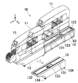
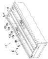
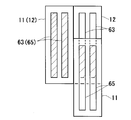
- FIG. 1 is a perspective view showing an embodiment of a component mounting apparatus according to the present invention. It is a perspective view which shows the state which pulled out the module of the component mounting apparatus of FIG. 1 with respect to the base. It is a perspective view which shows the detail of the base of the component mounting apparatus of FIG. It is a partial cross section side view which shows the module and base of the component mounting apparatus of FIG. It is a figure which shows the electric power system of the component mounting apparatus of FIG. It is a figure which shows the positional relationship of the electric field coupling receiving part provided in the module when the module of the component mounting apparatus of FIG. 1 is positioned in the mounting position and the adjustment position, and the electric field coupling power transmission part provided in the base. .
- the component mounting apparatus 10 includes two modules 11 and one base 12 that supports each module 11 so that it can be pulled out from the working position (the state shown in FIG. 1) in the horizontal direction (Y-axis direction). ing.
- the module 11 includes a component supply device 20, a component mounting device 30, a substrate transfer device 50, and a control device 40 (corresponding to “work control means” of the present invention), and a direction (Y-axis direction) orthogonal to the drawing direction (Y-axis direction). Two units are arranged side by side in the X-axis direction).
- the component supply device 20, the component mounting device 30, the control device 40, and the board transfer device 50 are devices having known configurations, and the schematic configuration will be described below.
- FIG. 1 shows a component mounting apparatus 10 in which two modules 11 are arranged side by side in a direction (X-axis direction) perpendicular to the drawing direction (Y-axis direction) on one base 12.
- the component supply device 20 is of a cassette type in which a plurality of feeders 21 are arranged in parallel on the base frame 11a of the module 11.
- the feeder 21 includes a feeder main body 22 that is detachably attached to the base frame 11 a, a supply reel 23 that is detachably attached to the rear part of the feeder main body 22, and a component supply unit 24 that is provided at the tip of the feeder main body 22.
- a carrier tape in which components are enclosed at a predetermined pitch is wound and held on the supply reel 23.
- the carrier tape is pulled out from the supply reel 23 at a predetermined pitch by a sprocket (not shown), and the components released from the enclosed state are sequentially fed into the component supply unit 24.
- the component mounting device 30 is composed of an XY robot, and the XY robot is mounted on the base 11b of the module 11 and is disposed above the substrate transfer device 50 and the component supply device 20.
- the XY robot includes a Y-axis slide 31 movable in the Y-axis direction and an X-axis slide 32 movable in the X-axis direction.
- a component mounting head 33 having a suction nozzle (not shown) is provided on the X-axis slide 32.
- a component recognition camera 34 is fixed on the base 11b.
- the component sucked by the suction nozzle is captured by the component recognition camera 34 while moving from the component supply unit 24 of the component supply device 20 to a predetermined position on the substrate S. Then, the misalignment of the component with respect to the center of the suction nozzle is detected, and the movement amount of the component mounting head 33 in the X and Y directions is corrected based on this misalignment.
- the control device 40 is mainly a computer (not shown) having a CPU, a ROM, a RAM, an input / output interface, and a bus connecting them.
- a motor drive circuit 41 (see FIG. 5) for driving a drive motor M (see FIG. 5) and the like provided in the component supply device 20 and the component mounting device 30 is connected to the input / output interface.
- the ROM stores, for example, a basic mounting program for executing component mounting.
- the substrate transfer apparatus 50 is of a double conveyor type in which two transfer apparatuses 51 are arranged side by side.
- the transfer device 51 horizontally arranges a pair of guide rails 52 facing each other in parallel on the base 11b of the module 11, and supports and transports the substrates S respectively guided by the guide rails 52.
- a pair of unillustrated conveyor belts are arranged to face each other.
- the substrate transport device 50 is provided with an unillustrated clamp device that lifts and clamps the substrate S transported to a predetermined position.
- the board conveying device 50 having such a configuration, the board S on which the component is mounted is conveyed to the part mounting position in the X-axis direction by the conveyor belt while being guided by the guide rail 52. Then, the substrate S transported to the component mounting position is positioned and clamped at the component mounting position by the clamp device.
- the module 11 can be fixed to the base 12 and can be moved relative to the base 12 in a direction (Y-axis direction) perpendicular to the arrangement direction (X-axis direction) of the plurality of modules 11.
- Y-axis direction perpendicular to the arrangement direction (X-axis direction) of the plurality of modules 11.
- X-axis direction arrangement direction
- the module 11 is fixed to the base 12 in a state where the entire module 11 is placed on the base 12 (the state of the module 11 on the back side in FIG. 2).
- This fixed position is a work position where a component mounting work is performed.
- the module 11 includes a mounting work position, an adjustment work position for performing maintenance work and the like in the module 11 (the position of the module 11 indicated by a one-dot chain line in FIG. 2), and a removal for removing the module 11 from the base 12. It is configured to be movable between positions (positions of modules 11 indicated by solid lines on the near side in FIG. 2). When the module 11 is moved to the removal position, the module 11 is placed on a table 13 (details will be described later) formed at the same height as the base 12. Thereby, each module 11 can be replaced and arranged, or the arrangement of the plurality of modules 11 in the arrangement direction can be arbitrarily set.
- two pairs of guide rails 121 are arranged on the upper surface of the base 12 so as to extend in parallel with the drawing-out direction (Y-axis direction) of the module 11.
- eight wheels 111 are rotatably supported through bearings in parallel in two rows in the pull-out direction (Y-axis direction). Yes.
- the distance between the two rows of wheels 111 is the same as the distance between the pair of guide rails 121, and the two rows of wheels 111 engage with each other so as to roll along the pair of guide rails 121.
- the pair of guide rails 121 guide the movement of one module 11 in the drawing direction (Y-axis direction).
- a positioning member 122 (corresponding to the “positioning means” of the present invention) for positioning the module 11 at the mounting work position;
- a positioning device 123 (corresponding to the “positioning means” of the present invention) is provided for maintaining the state positioned at the mounting work position and for positioning at the adjustment work position.
- the positioning member 122 is formed in an inverted L shape when viewed from the X-axis direction, and is fixed to the rear end portion of the upper surface of the base 12 so that the convex portion faces upward.
- the positioning device 123 includes a cylinder device 124 and a positioning member 125, and is built in a substantially central portion of the base 12.
- the rear end portion of the cylinder body 124a is rotatably supported on the back side of the upper surface of the base 12, and the positioning member 125 is rotatably supported on the front end portion of the rod 124b.
- the positioning member 125 is formed in an upside-down shape when viewed from the X-axis direction, and one end portion of the dogleg shape is rotatably supported on the tip end portion of the rod 124b, and the center portion of the dogleg shape is the base. 12 is rotatably supported on the back side of the upper surface of 12.
- the positioning member 125 rotates counterclockwise or clockwise around the center of the dogleg, and the other end of the dogleg of the positioning member 125 The top surface of the base 12 is retracted or pushed out.
- the bottom surface of the module 11 has a contact member 112 that contacts the positioning member 122 and the positioning member 125 of the positioning device 123, and a biased member 113 that is biased by the positioning member 125.
- the contact member 112 is formed in a rectangular parallelepiped shape and is fixed to the rear end portion of the bottom surface of the module 11.
- the biased member 113 is formed in a rectangular parallelepiped shape and is fixed to a substantially central portion of the bottom surface of the module 11.
- the contact member 112 of the module 11 contacts the positioning member 122 of the base 12, and the movement of the module 11 is restricted.
- the cylinder device 124 of the base 12 is activated, the rod 124b is retracted into the cylinder body 124a, the positioning member 125 is pushed out from the upper surface of the base 12, and the biased member 113 of the module 11 is biased toward the positioning member 122. To do.
- the module 11 is positioned and fixed at the mounting work position.
- the cylinder device 124 of the base 12 When the module 11 is moved from the mounting work position to the adjustment work position, the cylinder device 124 of the base 12 is operated, the rod 124b protrudes from the cylinder body 124a, and the positioning member 125 is separated from the biased member 113 and moved to the base. 12 from the top surface.
- the operator pulls out the module 11 until the biased member 113 of the module 11 passes over the positioning member 125 of the base 12.
- the cylinder device 124 of the base 12 is actuated again, the rod 124b is drawn into the cylinder body 124a, and the positioning member 125 is pushed out from the upper surface of the base 12.
- the module 11 is positioned at the adjustment work position.
- the table 13 When moving the module 11 from the adjustment work position to the removal position, the operator moves the table 13 to the front of the base 12.
- the table 13 has a width that is slightly larger than the width of the module 11 in the X-axis direction, is approximately the same length as the length of the module 11 in the Y-axis direction, and is substantially the same as the upper surface of the base 12.
- the upper surface has the same height.
- a pair of guide rails 131 are provided at the same interval with the same cross-sectional shape as the guide rails 121 of the base 12.
- the positioning member 132 and the positioning device 133 have the same configuration as the positioning member 122 and the positioning device 123 of the base 12, and detailed description thereof is omitted.
- wheels 134 are provided at the lower portion of the table 13 and are configured to be easily movable by human power.
- the table 13 is positioned and arranged in front of the base 12 so that the pair of guide rails 131 of the table 13 having such a configuration is in a state in which the pair of guide rails 121 of the base 12 is extended. Then, the cylinder device 124 of the base 12 operates, the rod 124b protrudes with respect to the cylinder main body 124a, and the positioning member 125 is separated from the contact member 112 of the module 11 and pulled from the upper surface of the base 12.
- a contact member (not shown) provided on the near side of the bottom surface of the module 11 contacts the positioning member 132 of the table 13, The movement of the module 11 is restricted.
- the positioning device 133 of the table 13 is activated, and the biased member 113 of the module 11 is biased toward the positioning member 132 side. Thereby, the module 11 is positioned and fixed on the table 13.
- the component mounting apparatus 10 includes a power supply device 60 that supplies power from the base 12 to the module 11 by electric field coupling.
- the power supply device 60 includes a power output unit 61, an electric field coupling control unit 62, an electric field coupling power transmission unit 63, a base communication control unit 64, an electric field coupling power reception unit 65, and a module communication control unit 66.
- the power output unit 61 can supply power to each module 11, one power output unit 61 is provided on the base 12.
- the electric field coupling control unit 62, the electric field coupling power transmission unit 63, and the base communication control unit 64 are provided on the base 12 corresponding to each module 11.
- the electric field coupling power receiving unit 65 and the module communication control unit 66 are provided in each module 11.
- the power output unit 61 is, for example, an AC power supply having a frequency of 50 Hz to 60 Hz and a voltage of 200 V, and power for operating the motor drive circuits 41 and the like of the control devices 40 provided in the two modules 11 by one. Is output.
- the electric field coupling control unit 62 is, for example, an inverter that converts the AC frequency from the power output unit 61 from 50 Hz to 60 Hz to 100 kHz, and is connected to the power output unit 61 to supply power to the control device 40. Electric power supplied from the output unit 61 to the electric field coupling power transmission unit 63 is transmitted to the electric field coupling power reception unit 65 to be received.
- the electric field coupling power transmission unit 63 is a pair of electrodes formed in a band shape, and is connected to the electric field coupling control unit 62 and, as shown in FIG. 6, the base 12 extends in parallel with the drawing direction of the module 11. Is provided on the upper surface of the.
- the electric field coupling power receiving unit 65 is a pair of electrodes formed in a band shape, is connected to the motor drive circuit 41 of the control device 40, etc., extends in the pull-out direction of the module 11, and the module 11 is at the mounting work position.
- the module 11 is provided on the bottom surface of the module 11 so as to face and separate from the electric field coupling power transmission unit 63 in the positioned state. That is, as shown in the module 11 and the base 12 on the left side of FIG. 6, when the module 11 is positioned at the mounting work position with respect to the base 12, the electric field coupling power transmission unit 63 and the electric field coupling power reception unit 65 When viewed from the Z-axis direction, substantially the whole (the hatched portion in the figure) overlaps. Therefore, the power supply device 60 has the maximum amount of power transmitted from the base 12 to the module 11 due to electric field coupling, and can supply the power necessary for the mounting work.
- the portion 63 and the electric field coupling power receiving portion 65 partially overlap (the hatched portion in the drawing).
- the electric field coupling has a property that the efficiency of power supply is not easily lowered even if the electric field coupling power transmission unit 63 and the electric field coupling power reception unit 65 are not aligned with high accuracy. The amount of power proportional to the degree is supplied.
- the power supply device 60 is smaller than when the module is positioned at the mounting work position from the base 12 to the module 11 by electric field coupling, but is necessary for the adjustment work. Power can be supplied.
- the power required for the adjustment work may be less than the power required for the mounting work.
- the power supply amount when the module 11 is positioned at the adjustment work position and the adjustment work is performed is larger than the power supply amount when the module 11 is positioned at the mounting work position and the mounting work is performed.
- the output power of the electric field coupling controller 62 may be controlled to be smaller than when the module is positioned at the mounting work position.
- the base communication control unit 64 includes a signal generator 641, a receiver 642, and a base memory 643.
- the base memory 643 stores table data in which the identification information of the module 11 and the characteristic value unique to the module 11 are associated, and version upgrade data such as a work program in the module 11, such as a component mounting program.
- the signal generator 641 and the receiver 642 of the base communication control unit 64 are connected via a capacitor coupling 67 in the middle of the connection between the electric field coupling control unit 62 and one of the electric field coupling power transmission units 63. 5V power is supplied.
- the module communication control unit 66 includes a signal generator 661, a receiver 662, and a module memory 663.
- the module memory 663 stores identification information of the module 11 and work programs in the module 11, such as a component mounting program.
- the signal generator 661 and the receiver 662 of the module communication control unit 66 are connected via a capacitor coupling 68 in the middle of the connection between the control device 40 and one of the electric field coupling power receiving units 65, for example, 1.5V to 5V Power is supplied.
- the base communication control unit 64 and the module communication control unit 66 communicate with each other via the electric field coupling power transmission unit 63 and the electric field coupling power reception unit 65.
- the module 11 When a component mounting operation is performed on the board, the module 11 is positioned and fixed at the mounting operation position. In this state, the electric field coupling power transmission unit 63 and the electric field coupling power reception unit 65 are substantially entirely overlapped when viewed from the Z-axis direction, and a large amount of electric power required for mounting work is generated from the base 12 by electric field coupling.
- the module 11 can be supplied.
- the base communication control unit 64 acquires the identification information of the module 11 from the module communication control unit 66, and identifies the characteristic value unique to the module corresponding to the identification information of the module 11. Then, the electric field coupling control unit 62 controls the power supply amount based on the specified characteristic value. Thereby, the component supply apparatus 20 and the component mounting apparatus 30 are operated, and component mounting is performed. Note that the base communication control unit 64 reads version upgrade data such as a component mounting program from the module communication control unit 66 when the power is turned on, for example, and updates the component mounting program and the like as necessary.
- the operator pulls out the module 11 with respect to the base 12, moves from the mounting work position to the adjustment work position, and positions it.
- the electric field coupling power transmission unit 63 and the electric field coupling power reception unit 65 partially overlap when viewed from the Z-axis direction, and small electric power required for adjustment work is generated from the base 12 by electric field coupling.
- the module 11 can be supplied. Thereby, the worker can perform adjustment work such as maintenance of the component supply device 20 and the component mounting device 30.
- the electric field coupling control unit 62 may be controlled so as to supply power necessary for a drive motor or the like that is operated during the adjustment work. .
- the component mounting apparatus 10 of the present embodiment since electric power is supplied from the base 12 to the module 11 by electric field coupling, the electric field coupling power transmission unit 63 and the electric field coupling power reception unit 65 are provided. Even if alignment is not performed with high accuracy, the efficiency of power supply is unlikely to decrease. Therefore, there is no need for an alignment means capable of highly accurate alignment of the power transmission / reception units 63 and 65, and the component mounting apparatus 10 capable of supplying power can be configured with a simple configuration.
- the electric field coupling power transmission unit 63 is provided on the base 12 so as to extend in the pull-out direction of the module 11, and the electric field coupling power receiving unit 65 extends in the pull-out direction of the module 11 and is electric power transmission for electric field coupling.
- the module 11 is provided so as to be separated from the portion 63 and at least partially face the portion 63. Therefore, when the module 11 is pulled out and the work is performed, the degree of overlap between the electric field coupling power transmission unit 63 and the electric field coupling power reception unit 65 is changed to meet the work by the single power output unit 61. It is possible to supply power. And since it becomes the single electric power output part 61, an apparatus cost can be reduced.
- the module 11 is configured to be able to be pulled out to a position where the adjustment work is performed with respect to the base 12, and further configured to be able to supply power from the base 12 at a position where the adjustment work is performed. Can be done smoothly. Further, it is not necessary to provide two power transmission / reception units for mounting work and adjustment work, and the apparatus cost can be reduced. Further, when the module 11 is pulled out from the base 12, there is no need to turn off the power supply and remove the wiring as in the conventional case, and the work load when performing the adjustment work is reduced.
- the power supply amount to the module 11 when the module 11 is pulled out from the base 12 is smaller than the power supply amount before the module 11 is pulled out, but the necessary power amount is also small, so the range of the necessary supply amount
- the power can be supplied within the power source, and there is no supply loss, and an energy saving effect can be achieved.
- the module 11 and the base 12 are respectively provided with a module communication control unit 66 and a base communication control unit 64 that communicate with each other. Therefore, it is not necessary to provide another dedicated communication circuit, and the component mounting apparatus 10 capable of signal transmission can be configured with a simple configuration.
- the base communication control unit 64 acquires the identification information of the module 11 from the module communication control unit 66, and specifies the unique characteristic value of the module 11 corresponding to the identification information of the module 11. Therefore, the electric field coupling control unit 62 can adjust the power supply amount based on the characteristic value unique to the module 11. As a result, when the module 11 is replaced with another module 11 or the like, the work of resetting the unique characteristic value of the replaced module 11 becomes unnecessary, and the number of work steps can be reduced. Further, since the base 12 is provided with positioning devices 122 and 123 for positioning the module 11 at the mounting work position or the adjustment work position, the operator pulls out or pushes the module 11 with respect to the base 12. It is possible to position at the mounting work position or the adjustment work position only by the inserting operation, and it is possible to quickly start the mounting work or the adjustment work.
- the component mounting apparatus 10 has been described as an example of the board working apparatus.
- the inspection machine that inspects the state of the components mounted on the board, and the like. Also, the present invention can be applied.
- the present invention can be used in a component mounter that mounts electronic components on a substrate.
Landscapes
- Engineering & Computer Science (AREA)
- Operations Research (AREA)
- Manufacturing & Machinery (AREA)
- Microelectronics & Electronic Packaging (AREA)
- Supply And Installment Of Electrical Components (AREA)
- Manipulator (AREA)
Abstract
L'invention porte sur un appareil de travail de substrat, pour lequel appareil une alimentation électrique et une transmission de signal sont possibles à l'aide d'une structure simple, et pour lequel la quantité d'énergie électrique fournie par une alimentation électrique unique peut être réglée. Dans un appareil de montage de composants (10), de l'énergie électrique est distribuée d'une base (12) à un module (11) par un couplage par champ électrique; par conséquent, le rendement de l'alimentation électrique n'est pas facilement réduit, même si une section d'émission d'énergie électrique (63) pour un couplage par champ électrique et une section de réception d'énergie électrique (65) pour un couplage par champ électrique ne sont pas alignées avec précision. Par conséquent, des moyens d'alignement qui peuvent aligner avec précision les sections d'émission et de réception d'énergie électrique (63, 65) sont inutiles et l'appareil de montage de composants (10), pour lequel une alimentation électrique est possible en présentant une structure simple, peut être obtenu. La section d'émission d'énergie électrique (63) pour un couplage par champ électrique et la section de réception d'énergie électrique (65) pour un couplage par champ électrique sont disposées dans le module (11) de façon à s'étendre dans la direction dans laquelle le module (11) est extrait et de façon à être espacées l'une de l'autre, se faisant mutuellement face dans au moins une partie. Par conséquent, la quantité d'énergie électrique qui peut être fournie par une section d'émission d'énergie électrique unique (61) peut être réglée par extraction du module (11) et modification de l'ampleur dont la section d'émission d'énergie électrique (63) pour couplage par champ électrique et la section de réception d'énergie électrique (65) pour couplage par champ électrique se chevauchent.
Priority Applications (1)
| Application Number | Priority Date | Filing Date | Title |
|---|---|---|---|
| CN201280007227.8A CN103340030B (zh) | 2011-02-03 | 2012-01-17 | 基板作业装置 |
Applications Claiming Priority (2)
| Application Number | Priority Date | Filing Date | Title |
|---|---|---|---|
| JP2011021283A JP5704944B2 (ja) | 2011-02-03 | 2011-02-03 | 基板作業装置 |
| JP2011-021283 | 2011-02-03 |
Publications (2)
| Publication Number | Publication Date |
|---|---|
| WO2012105309A1 true WO2012105309A1 (fr) | 2012-08-09 |
| WO2012105309A8 WO2012105309A8 (fr) | 2012-09-27 |
Family
ID=46602529
Family Applications (1)
| Application Number | Title | Priority Date | Filing Date |
|---|---|---|---|
| PCT/JP2012/050830 Ceased WO2012105309A1 (fr) | 2011-02-03 | 2012-01-17 | Appareil de travail de plaque de substrat |
Country Status (3)
| Country | Link |
|---|---|
| JP (1) | JP5704944B2 (fr) |
| CN (1) | CN103340030B (fr) |
| WO (1) | WO2012105309A1 (fr) |
Cited By (2)
| Publication number | Priority date | Publication date | Assignee | Title |
|---|---|---|---|---|
| CN106714543A (zh) * | 2017-02-24 | 2017-05-24 | 珠海市泽良电子有限公司 | 一种小型电路板贴片机 |
| EP3606311A4 (fr) * | 2017-03-30 | 2020-03-11 | Fuji Corporation | Machine de traitement de substrat |
Families Citing this family (9)
| Publication number | Priority date | Publication date | Assignee | Title |
|---|---|---|---|---|
| JP6161683B2 (ja) * | 2013-02-15 | 2017-07-12 | 富士機械製造株式会社 | 静電結合方式非接触給電装置 |
| JP6320725B2 (ja) * | 2013-11-20 | 2018-05-09 | ハンファテクウィン株式会社Hanwha Techwin Co.,Ltd. | 部品実装機 |
| JP6322391B2 (ja) * | 2013-11-20 | 2018-05-09 | ハンファテクウィン株式会社Hanwha Techwin Co.,Ltd. | 作業機械 |
| EP3544034B1 (fr) * | 2016-11-15 | 2023-09-27 | FUJI Corporation | Unité de connexion d'alimentation électrique sans contact, dispositif d'alimentation électrique sans contact et machine d'exploitation |
| DE102017109677A1 (de) | 2017-05-05 | 2018-11-08 | Atm Gmbh | Einbettpresse, Absaugeinrichtung für eine Einbettpresse und modulares Einbettpressensystem |
| WO2019215781A1 (fr) * | 2018-05-07 | 2019-11-14 | 株式会社Fuji | Module d'actionnement de mouvement |
| JP7157564B2 (ja) * | 2018-06-11 | 2022-10-20 | 株式会社Fuji | 対基板作業機 |
| JP7035184B2 (ja) * | 2018-06-13 | 2022-03-14 | 株式会社Fuji | 対基板作業機 |
| JP7097988B2 (ja) * | 2018-11-30 | 2022-07-08 | 株式会社Fuji | 対基板作業機 |
Citations (6)
| Publication number | Priority date | Publication date | Assignee | Title |
|---|---|---|---|---|
| JPH09307283A (ja) * | 1996-05-15 | 1997-11-28 | Sony Corp | 部品供給装置 |
| JPH11317595A (ja) * | 1998-02-24 | 1999-11-16 | Juki Corp | 部品供給システム |
| JP2005347351A (ja) * | 2004-05-31 | 2005-12-15 | Yamaha Motor Co Ltd | 実装機、フィーダおよびフィーダ保持装置 |
| JP2007207976A (ja) * | 2006-02-01 | 2007-08-16 | Yamagata Casio Co Ltd | 部品実装装置 |
| JP2010161414A (ja) * | 2002-07-19 | 2010-07-22 | Fuji Mach Mfg Co Ltd | 対基板作業システム |
| JP2010283257A (ja) * | 2009-06-08 | 2010-12-16 | Juki Corp | 電子部品実装装置 |
Family Cites Families (1)
| Publication number | Priority date | Publication date | Assignee | Title |
|---|---|---|---|---|
| CN100508721C (zh) * | 2002-06-25 | 2009-07-01 | 富士机械制造株式会社 | 对基板作业系统 |
-
2011
- 2011-02-03 JP JP2011021283A patent/JP5704944B2/ja not_active Expired - Fee Related
-
2012
- 2012-01-17 WO PCT/JP2012/050830 patent/WO2012105309A1/fr not_active Ceased
- 2012-01-17 CN CN201280007227.8A patent/CN103340030B/zh active Active
Patent Citations (6)
| Publication number | Priority date | Publication date | Assignee | Title |
|---|---|---|---|---|
| JPH09307283A (ja) * | 1996-05-15 | 1997-11-28 | Sony Corp | 部品供給装置 |
| JPH11317595A (ja) * | 1998-02-24 | 1999-11-16 | Juki Corp | 部品供給システム |
| JP2010161414A (ja) * | 2002-07-19 | 2010-07-22 | Fuji Mach Mfg Co Ltd | 対基板作業システム |
| JP2005347351A (ja) * | 2004-05-31 | 2005-12-15 | Yamaha Motor Co Ltd | 実装機、フィーダおよびフィーダ保持装置 |
| JP2007207976A (ja) * | 2006-02-01 | 2007-08-16 | Yamagata Casio Co Ltd | 部品実装装置 |
| JP2010283257A (ja) * | 2009-06-08 | 2010-12-16 | Juki Corp | 電子部品実装装置 |
Cited By (3)
| Publication number | Priority date | Publication date | Assignee | Title |
|---|---|---|---|---|
| CN106714543A (zh) * | 2017-02-24 | 2017-05-24 | 珠海市泽良电子有限公司 | 一种小型电路板贴片机 |
| EP3606311A4 (fr) * | 2017-03-30 | 2020-03-11 | Fuji Corporation | Machine de traitement de substrat |
| US11343951B2 (en) | 2017-03-30 | 2022-05-24 | Fuji Corporation | Substrate processing machine |
Also Published As
| Publication number | Publication date |
|---|---|
| JP5704944B2 (ja) | 2015-04-22 |
| CN103340030B (zh) | 2016-05-18 |
| WO2012105309A8 (fr) | 2012-09-27 |
| CN103340030A (zh) | 2013-10-02 |
| JP2012160676A (ja) | 2012-08-23 |
Similar Documents
| Publication | Publication Date | Title |
|---|---|---|
| JP5704944B2 (ja) | 基板作業装置 | |
| CN105075421B (zh) | 通信系统及电子元件安装装置 | |
| CN106068074B (zh) | 基板输送装置及电子部件安装装置 | |
| JP2008277452A (ja) | 電子部品装着装置 | |
| JP5850656B2 (ja) | 基板搬送装置 | |
| CN103857270B (zh) | 电子元件的安装方法以及表面安装机 | |
| CN103125153B (zh) | 电子元件安装机 | |
| CN103619594B (zh) | 网版印刷装置 | |
| JP6219838B2 (ja) | 部品実装機 | |
| US9346625B2 (en) | Work system for substrates and working machine | |
| EP2897449B1 (fr) | Système de travail pour substrat et programme de détermination de quantité de poste de travail | |
| CN105960834A (zh) | 电子元件安装装置 | |
| JP4822282B2 (ja) | 部品装着機及びその使用方法 | |
| JP5946287B2 (ja) | 部品装着装置 | |
| CN110313124B (zh) | 马达控制装置及供料器 | |
| US10834859B2 (en) | Component mounting device | |
| KR20010025827A (ko) | 표면실장장치 및 그 실장방법 | |
| JP7097988B2 (ja) | 対基板作業機 | |
| CN103619593A (zh) | 网版印刷装置 | |
| JP2019207958A (ja) | 部品実装装置 | |
| JP3079062B2 (ja) | 表面実装機 | |
| CN113545184A (zh) | 伺服放大器系统 | |
| JP2001291996A (ja) | モジュール型部品実装装置 | |
| JP5847318B2 (ja) | 光無線通信器を有する駆動装置 | |
| JPH11145689A (ja) | 表面実装機 |
Legal Events
| Date | Code | Title | Description |
|---|---|---|---|
| 121 | Ep: the epo has been informed by wipo that ep was designated in this application |
Ref document number: 12742189 Country of ref document: EP Kind code of ref document: A1 |
|
| NENP | Non-entry into the national phase |
Ref country code: DE |
|
| 122 | Ep: pct application non-entry in european phase |
Ref document number: 12742189 Country of ref document: EP Kind code of ref document: A1 |