WO2012105363A1 - Batterie hermétiquement scellée de forme cylindrique - Google Patents
Batterie hermétiquement scellée de forme cylindrique Download PDFInfo
- Publication number
- WO2012105363A1 WO2012105363A1 PCT/JP2012/051398 JP2012051398W WO2012105363A1 WO 2012105363 A1 WO2012105363 A1 WO 2012105363A1 JP 2012051398 W JP2012051398 W JP 2012051398W WO 2012105363 A1 WO2012105363 A1 WO 2012105363A1
- Authority
- WO
- WIPO (PCT)
- Prior art keywords
- outer container
- electrode plate
- battery
- electrode tab
- negative electrode
- Prior art date
- Legal status (The legal status is an assumption and is not a legal conclusion. Google has not performed a legal analysis and makes no representation as to the accuracy of the status listed.)
- Ceased
Links
Images


Classifications
-
- H—ELECTRICITY
- H01—ELECTRIC ELEMENTS
- H01M—PROCESSES OR MEANS, e.g. BATTERIES, FOR THE DIRECT CONVERSION OF CHEMICAL ENERGY INTO ELECTRICAL ENERGY
- H01M50/00—Constructional details or processes of manufacture of the non-active parts of electrochemical cells other than fuel cells, e.g. hybrid cells
- H01M50/50—Current conducting connections for cells or batteries
- H01M50/543—Terminals
- H01M50/552—Terminals characterised by their shape
- H01M50/559—Terminals adapted for cells having curved cross-section, e.g. round, elliptic or button cells
- H01M50/56—Cup shaped terminals
-
- H—ELECTRICITY
- H01—ELECTRIC ELEMENTS
- H01M—PROCESSES OR MEANS, e.g. BATTERIES, FOR THE DIRECT CONVERSION OF CHEMICAL ENERGY INTO ELECTRICAL ENERGY
- H01M50/00—Constructional details or processes of manufacture of the non-active parts of electrochemical cells other than fuel cells, e.g. hybrid cells
- H01M50/50—Current conducting connections for cells or batteries
- H01M50/531—Electrode connections inside a battery casing
- H01M50/533—Electrode connections inside a battery casing characterised by the shape of the leads or tabs
-
- H—ELECTRICITY
- H01—ELECTRIC ELEMENTS
- H01M—PROCESSES OR MEANS, e.g. BATTERIES, FOR THE DIRECT CONVERSION OF CHEMICAL ENERGY INTO ELECTRICAL ENERGY
- H01M50/00—Constructional details or processes of manufacture of the non-active parts of electrochemical cells other than fuel cells, e.g. hybrid cells
- H01M50/50—Current conducting connections for cells or batteries
- H01M50/528—Fixed electrical connections, i.e. not intended for disconnection
-
- H—ELECTRICITY
- H01—ELECTRIC ELEMENTS
- H01M—PROCESSES OR MEANS, e.g. BATTERIES, FOR THE DIRECT CONVERSION OF CHEMICAL ENERGY INTO ELECTRICAL ENERGY
- H01M10/00—Secondary cells; Manufacture thereof
- H01M10/05—Accumulators with non-aqueous electrolyte
- H01M10/052—Li-accumulators
-
- H—ELECTRICITY
- H01—ELECTRIC ELEMENTS
- H01M—PROCESSES OR MEANS, e.g. BATTERIES, FOR THE DIRECT CONVERSION OF CHEMICAL ENERGY INTO ELECTRICAL ENERGY
- H01M10/00—Secondary cells; Manufacture thereof
- H01M10/05—Accumulators with non-aqueous electrolyte
- H01M10/058—Construction or manufacture
- H01M10/0587—Construction or manufacture of accumulators having only wound construction elements, i.e. wound positive electrodes, wound negative electrodes and wound separators
-
- H—ELECTRICITY
- H01—ELECTRIC ELEMENTS
- H01M—PROCESSES OR MEANS, e.g. BATTERIES, FOR THE DIRECT CONVERSION OF CHEMICAL ENERGY INTO ELECTRICAL ENERGY
- H01M10/00—Secondary cells; Manufacture thereof
- H01M10/34—Gastight accumulators
- H01M10/345—Gastight metal hydride accumulators
-
- Y—GENERAL TAGGING OF NEW TECHNOLOGICAL DEVELOPMENTS; GENERAL TAGGING OF CROSS-SECTIONAL TECHNOLOGIES SPANNING OVER SEVERAL SECTIONS OF THE IPC; TECHNICAL SUBJECTS COVERED BY FORMER USPC CROSS-REFERENCE ART COLLECTIONS [XRACs] AND DIGESTS
- Y02—TECHNOLOGIES OR APPLICATIONS FOR MITIGATION OR ADAPTATION AGAINST CLIMATE CHANGE
- Y02E—REDUCTION OF GREENHOUSE GAS [GHG] EMISSIONS, RELATED TO ENERGY GENERATION, TRANSMISSION OR DISTRIBUTION
- Y02E60/00—Enabling technologies; Technologies with a potential or indirect contribution to GHG emissions mitigation
- Y02E60/10—Energy storage using batteries
-
- Y—GENERAL TAGGING OF NEW TECHNOLOGICAL DEVELOPMENTS; GENERAL TAGGING OF CROSS-SECTIONAL TECHNOLOGIES SPANNING OVER SEVERAL SECTIONS OF THE IPC; TECHNICAL SUBJECTS COVERED BY FORMER USPC CROSS-REFERENCE ART COLLECTIONS [XRACs] AND DIGESTS
- Y02—TECHNOLOGIES OR APPLICATIONS FOR MITIGATION OR ADAPTATION AGAINST CLIMATE CHANGE
- Y02P—CLIMATE CHANGE MITIGATION TECHNOLOGIES IN THE PRODUCTION OR PROCESSING OF GOODS
- Y02P70/00—Climate change mitigation technologies in the production process for final industrial or consumer products
- Y02P70/50—Manufacturing or production processes characterised by the final manufactured product
Definitions
- the present invention relates to a cylindrical sealed battery with improved reliability.
- Non-aqueous electrolyte secondary batteries typified by lithium ion batteries and alkaline storage batteries typified by nickel metal hydride batteries are characterized by high energy density, so not only power sources for portable devices, but also power tools and electric vehicles, Applications are expanding to power sources such as power storage.
- lithium ion batteries use lithium transition metal oxides such as lithium cobaltate, lithium nickelate, and lithium manganate that can reversibly occlude and release lithium ions as a positive electrode active material.
- the positive electrode active material is mixed with a binder, a conductive agent, and the like, applied onto an aluminum foil, and used as a positive electrode plate.
- the negative electrode active material carbonaceous materials such as natural graphite, artificial graphite, coke, silicon, tin and their alloys, oxides, and the like are used. And a negative electrode active material is mixed with a binder etc., and it apply
- the positive electrode plate and the negative electrode plate are processed into predetermined dimensions, wound into a cylindrical shape through a resin microporous separator to form a wound body, and sealed in a cylindrical outer container together with an electrolyte.
- a bottomed cylindrical shape or a rectangular parallelepiped shape, and a metal bottomed outer container having one opening is often used.
- Such exterior containers may be provided with irregularities on the surface or the inner surface for various purposes.
- Patent Document 1 discloses a battery in which a concave portion or a convex portion serving as a nail hook is provided on the bottom of an outer container in order to facilitate removal of the battery stored in the device from a narrow space.
- Patent Document 2 discloses a battery in which a concave portion is provided on the bottom of a can inside the battery in order to hold an electrolyte necessary for the battery reaction in the outer container.
- Batteries that serve as power sources for various devices are constantly required to have high capacity and high reliability.
- the thickness of the metal material of the outer container is reduced, the active material density of the electrode is increased, or the electrode width is increased.
- the thickness of the outer container material is reduced, when the battery is processed into a battery pack or the like, if welding is performed on the outer container, a hole may be formed in the outer container and the electrolyte may leak from the hole. Further, when the density of the electrode is increased, the electrolytic solution is less likely to penetrate the electrode.
- the width of the separator that insulates both electrodes also increases, so that the height of the winding body increases.
- the electrode tab led out from the wound body is bent and welded near the bottom surface of the outer container.
- the opening of an exterior container is sealed using a sealing body.
- a constriction is provided below the opening of the outer container.
- the winding body is pressed from the upper side toward the bottom surface.
- the electrode tab may be bent excessively near the bent portion.
- the electrode of the winding body Due to the bending of the extra electrode tab, the electrode of the winding body is also bent, which may cause a short circuit. Even in a battery in which the outer container is not constricted, since the height of the outer container is constant, the same problem may occur when the width of the electrode plate is increased.
- the present invention has been made in view of such problems, and an object thereof is to provide a cylindrical sealed battery having a high capacity while maintaining reliability.
- the cylindrical sealed battery according to the first aspect of the present invention for solving the above problems includes a wound body in which a positive electrode plate and a negative electrode plate are wound via a separator, and an electrolyte in a cylindrical outer container.
- An electrode tab connected to either the positive electrode plate or the negative electrode plate protrudes from the winding body toward the bottom surface of the bottomed outer packaging container, and the electrode tab extends from the winding body to the outer packaging container.
- the outer container is connected to the bottom surface of the outer container with a bent portion between the inner bottom surface, and the outer container has a concave portion on the bottom surface facing the bent portion of the electrode tab.
- the electrode tab can move to the concave portion of the outer container without causing excessive bending even when the winding body is pushed from the upper part of the battery toward the bottom of the outer container. Therefore, the electrode of the wound body is not bent, and a short circuit can be prevented.
- the cylindrical sealed battery according to the second aspect of the present invention is characterized in that the bottom surface outside the outer container is flat.
- the lead connected to the external circuit etc. is welded to the bottom surface outside the outer container, but the bottom surface of the outer container is flat. Because there is, welding becomes easy.
- the cylindrical sealed battery according to the third aspect of the present invention is characterized in that the outer container material thickness in the recess at the bottom of the outer container is 0.1 mm or more.
- the outer container material thickness in the concave portion at the bottom of the outer container is 0.1 mm or more because strength required for the outer container can be maintained. At this time, it is preferable to set the depth of the recess to 0.05 to 0.40 mm because the battery capacity can be increased without causing excessive bending of the electrode tab.
- the cylindrical sealed battery according to the fourth aspect of the present invention is characterized in that the material thickness of the outer container other than the concave portion at the bottom of the outer container is 0.2 to 0.5 mm.
- the outer container material thickness is preferably 0.2 to 0.5 mm.
- the electrode tab led out from the wound body is not bent excessively, and the electrode of the wound body is not bent. Since no bending occurs, a short circuit can be prevented. Therefore, a cylindrical sealed battery with high reliability and high battery capacity can be provided.
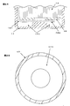
- FIG. 2A is a cross-sectional view in the height direction of the cylindrical sealed battery according to Example 1 and Example 2, and is a cross-sectional view of the main part around the bottom of the outer container before constricting the lower part of the opening of the outer container. It is the top view which looked at the bottom face from the opening side of the exterior container used for Example 1 and Example 2.
- FIG. 3A is a cross-sectional view in the height direction of the cylindrical sealed battery according to Example 3 and Example 4, and is a cross-sectional view of a main part around the bottom of the outer container before the constriction is inserted into the lower part of the outer container opening.
- FIG. 4A is a cross-sectional view in the height direction of the cylindrical sealed battery according to Comparative Example 1, Comparative Example 2, and Comparative Example 3, and is a cross-sectional view of the main part around the bottom of the outer container before constricting the lower part of the outer container opening.
- FIG. 4B is a plan view of the outer container used in Comparative Example 1, Comparative Example 2, and Comparative Example 3 as viewed from the opening side.
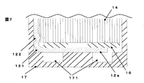
- Example 5 is a cross-sectional view in the height direction of the cylindrical sealed battery according to Comparative Example 4 and Comparative Example 5, and is a cross-sectional view of the main part around the bottom of the outer container before the constriction is placed in the lower part of the outer container opening. It is a height direction cross section of the cylindrical sealed battery which concerns on Example 1 and Example 2, Comprising: It is principal part sectional drawing of the exterior container bottom part periphery, The exterior container bottom part periphery after putting a constriction in the exterior container opening lower part It is principal part sectional drawing.
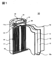
- FIG. 1 is a perspective view showing a cylindrical nonaqueous electrolyte secondary battery manufactured in the embodiment cut in the vertical direction.
- the non-aqueous electrolyte secondary battery 10 of the example uses a winding body 14 in which a positive electrode plate 11 and a negative electrode plate 12 are wound in a spiral shape with a separator 13 interposed therebetween.
- Insulation plates 15 and 16 are arranged on the upper and lower sides of the wound body 14, respectively, and are housed in an iron outer case 17 having a bottomed cylindrical shape and nickel-plated on the surface.
- the electrode tab 12a of the negative electrode plate 12 is welded to the inner bottom of the outer can 17, and the electrode tab 11a of the positive electrode plate 11 is equipped with a safety valve 18 and is welded to the bottom of the sealing body 19 serving as a positive electrode terminal.
- a non-aqueous electrolyte (not shown) is injected into the outer can 17, and the opening of the outer can 17 is sealed with a sealing body 19 via a gasket 21.
- the method for producing the non-aqueous electrolyte secondary battery is as follows.
- ⁇ Preparation of positive electrode plate> 94: 3: 3 (mass ratio) of positive electrode active material in which nickel manganese lithium cobaltate and lithium cobaltate were mixed at a mass ratio of 1: 9, carbon black as a conductive agent, and polyvinylidene fluoride as a binder.
- the mixture was dispersed in N-methyl-2-pyrrolidone to obtain a paste.
- This paste was uniformly applied to both sides of a 15 ⁇ m thick aluminum foil by a doctor blade method and dried by heating to produce a dry electrode plate having an active material layer formed on the aluminum foil.
- the dried electrode plate was compressed to a thickness of 0.13 mm with a roller press, and the width and length were cut into predetermined dimensions, and then the electrode tab 11a was attached to produce the positive electrode plate 11.
- Graphite as a negative electrode active material, styrene butadiene rubber as a binder, and carboxymethyl cellulose as a viscosity modifier were mixed at 96: 2: 2 (mass ratio), and the mixture was dispersed in water to obtain a paste.
- This paste was uniformly applied to both surfaces of a 10 ⁇ m thick copper foil by a doctor blade method and dried by heating to produce a dry electrode plate having an active material layer formed on the copper foil.
- the dried electrode plate was compressed to a thickness of 0.12 mm with a roller press, and the width and length were cut into predetermined dimensions, and then the electrode tab 12a was attached to produce the negative electrode plate 12.
- a winding body winds the said positive electrode plate 11, the negative electrode plate 12, and the polyethylene microporous separator 13 using a winding machine so that the positive electrode plate 11 and the negative electrode plate 12 may be insulated by the separator 13.
- FIG. Produced.
- Lithium hexafluorophosphate as an electrolyte salt was dissolved in an amount of 1.2 mol / liter in a non-aqueous solvent in which ethylene carbonate and ethyl methyl carbonate were mixed at a volume ratio of 30:70 (25 ° C., 1 atm).
- An electrolyte was prepared by dissolving vinylene carbonate in an amount of 2% by mass as an additive.
- ⁇ Preparation of exterior container> A steel plate having a thickness of 0.3 mm was cut out to a predetermined area. And the circumferential recessed part was formed in the part used as the battery inner side bottom face of the exterior container of the cut-out steel plate by forging. Thereafter, the outer container 17 was formed by performing DI processing using a punch and a die to form the shape of the outer container and trimming it to a predetermined height. The material thickness of the bottom surface of the outer container other than the recesses was 0.3 mm. The recess on the bottom surface of the outer container may be processed by cutting the bottom after forming the shape of the outer container.
- ⁇ Battery assembly> The insulating plate 16 was attached to the wound body 14 and stored in the outer container 17, and the negative electrode plate electrode tab 12 a was welded to the inner can bottom of the outer container 17. Then, the insulating plate 15 was attached to the upper part of the winding body 14, a circumferential constriction 22 was formed in the lower part of the opening of the outer container 17, and the gasket 21 was placed on the constriction 22. Further, the positive electrode tab 11 a was welded to the bottom of the sealing body 19.
- a cylindrical nonaqueous electrolyte secondary battery (diameter 18 mm, height 65 mm).
- Example 1 In the cylindrical non-aqueous electrolyte secondary battery, as shown in FIGS. 2A and 2B, the bottom surface on the inner side of the outer container has an inner diameter of 10 mm, an outer diameter of 17.5 mm, and a depth centered on the center point of the outer container bottom surface.
- a recess 171 was formed to be 0.2 mm.
- the width of the positive electrode plate was 55.7 mm, and the width of the negative electrode plate was 57.7 mm.
- the electrode width and the separator width are wider by 0.2 mm than the electrode width of Comparative Example 1 described later. Further, as shown in FIG.
- the negative electrode tab 12a is led out from the outermost periphery of the winding body 14 to the bottom surface of the outer container and bent toward the center of the outer container at a position facing the concave portion of the bottom of the outer container (bent portion 121). Spot welding was performed at the center of the bottom of the outer container.
- the battery thus produced was referred to as Example 1.
- Example 2 In Example 1, it was the same except that the width of the positive electrode plate was 55.9 mm and the width of the negative electrode plate was 57.9 mm. This electrode width is 0.4 mm wider than the electrode width of Comparative Example 1 described later. The battery thus produced was referred to as Example 2.
- Example 3 In the cylindrical non-aqueous electrolyte secondary battery, as shown in FIGS. 3A and 3B, the bottom surface on the inner side of the outer container has an inner diameter of 10 mm, an outer diameter of 14 mm, and a depth of 0 centered on the center point of the outer container bottom surface. A recess was formed to be 2 mm. The width of the positive electrode plate was 55.7 mm, and the width of the negative electrode plate was 57.7 mm. This electrode width is wider by 0.2 mm than the electrode width and separator width of Comparative Example 1 described later. Further, as shown in FIG.
- the negative electrode tab 12a is led out from the middle of winding of the winding body 14 to the bottom surface of the outer container, and toward the center of the outer container at a position (bent portion 121) facing the concave portion at the bottom of the outer container. Bend and spot welded at the center of the bottom of the outer container.
- the battery thus manufactured was referred to as Example 3.
- Example 4 In Example 3, it was the same except that the width of the positive electrode plate was 55.9 mm and the width of the negative electrode plate was 57.9 mm. This electrode width is wider by 0.4 mm than the electrode width and separator width of Comparative Example 1 described later. The battery thus produced was referred to as Example 4.
- Comparative Example 1 As shown in FIGS. 4A and 4B, no recess was provided on the bottom surface of the outer container, the width of the positive electrode plate was 55.5 mm, the width of the negative electrode plate was 57.5 mm, and the width of the separator was 59.5 mm.
- the negative electrode tab 12a was led out from the outermost periphery of the wound body to the bottom surface of the outer container, bent at the bent portion 121 toward the center of the outer surface of the outer container, and spot welded at the center of the bottom surface of the outer container.
- the battery thus produced was designated as Comparative Example 1.
- Comparative Example 2 In Comparative Example 1, it was the same except that the width of the positive electrode plate was 55.7 mm and the width of the negative electrode plate was 57.7 mm. This electrode width is wider by 0.2 mm than the electrode width and separator width of Comparative Example 1. The battery thus produced was referred to as Comparative Example 2.
- Comparative Example 3 In Comparative Example 1, it was the same except that the width of the positive electrode plate was 55.9 mm and the width of the negative electrode plate was 57.9 mm. This electrode width is wider by 0.4 mm than the electrode width and separator width of Comparative Example 1. The battery thus produced was designated as Comparative Example 3.
- Comparative Example 4 In the battery of Example 3, as shown in FIG. 5, the negative electrode tab 12a is led out from the outermost periphery of the winding body 14 to the bottom surface of the outer container, bent at the bent portion 121 toward the center of the outer container, and the center of the bottom surface of the outer container Spot welded. The battery thus produced was designated as Comparative Example 4. Comparative Example 4 is different from Example 3 in that the negative electrode tab 12a is bent at a position that does not face the recess on the bottom surface of the outer container.
- Comparative Example 5 In the battery of Example 4, the negative electrode tab was led out from the outermost periphery of the wound body to the bottom of the outer container and welded. The battery thus produced was designated as Comparative Example 5. Comparative Example 5 is different from Example 4 in that the negative electrode tab 12a is bent at a position that does not face the recess on the bottom surface of the outer container.
- Table 1 shows the battery specifications and test results of the above Examples and Comparative Examples.
- the width of the positive electrode plate / negative electrode plate is The number of batteries in which excessive bending of the negative electrode tab and bending of the electrode of the winding body were observed even when the size was increased, were significantly smaller than in Comparative Examples 1 to 3.
- the depth of the concave portion on the bottom surface of the outer container is 25% or more, more preferably 30% or more, and 80% or less, more preferably 60% or less, of the material thickness of the outer container bottom. If the recess is made too deep, the thickness of the bottom surface of the outer container becomes too thin, which may cause a problem of strength. If there is an excessively large recess on the bottom surface of the outer container, the material thickness of the recess becomes thin, which may cause a problem of strength and hole opening in welding. Therefore, it is not preferable to make the concave portion excessively larger than necessary.
- the recess is formed so that the winding body may be rotated and the electrode tab may be led to any position on the circumference of the bottom surface of the outer container. It is preferably formed in a circumferential shape (doughnut shape).
- Nonaqueous electrolyte secondary battery 11 Positive electrode plate 11a Positive electrode tab 12 Negative electrode plate 12a Negative electrode tab 121
- the bending part of the electrode tab to the center of the exterior container 122 Excessive bending of the electrode tab 13 Separator 14 Winding bodies 15, 16 Insulating plate 17 Exterior container 171 Recess 18 Safety valve 19 Sealing body 21 Gasket 22 Neck
Landscapes
- Chemical & Material Sciences (AREA)
- Chemical Kinetics & Catalysis (AREA)
- Electrochemistry (AREA)
- General Chemical & Material Sciences (AREA)
- Secondary Cells (AREA)
- Sealing Battery Cases Or Jackets (AREA)
Abstract
L'invention vise à procurer une batterie secondaire à électrolyte non aqueux présentant une capacité élevée et une fiabilité élevée.
A cet effet, l'invention porte sur une batterie hermétiquement scellée de forme cylindrique, présentant un corps enroulé, dans lequel une plaque d'électrode positive et une plaque d'électrode négative sont enroulées en comprenant des séparateurs entre celles-ci, et un électrolyte hermétiquement scellé dans un récipient externe de forme cylindrique ayant un fond. La constitution est telle qu'une patte d'électrode qui est connectée soit à la plaque d'électrode positive soit à la plaque d'électrode négative fait saillie à partir du corps enroulé dans la direction de la surface inférieure du récipient externe ayant un fond. La patte d'électrode comporte une partie incurvée entre le corps enroulé et la surface inférieure interne du récipient externe et est connectée à la surface inférieure du récipient externe. Le récipient externe comporte une partie creuse sur la surface inférieure faisant face à la partie incurvée de la patte d'électrode.
Applications Claiming Priority (2)
| Application Number | Priority Date | Filing Date | Title |
|---|---|---|---|
| JP2011-017727 | 2011-01-31 | ||
| JP2011017727 | 2011-01-31 |
Publications (1)
| Publication Number | Publication Date |
|---|---|
| WO2012105363A1 true WO2012105363A1 (fr) | 2012-08-09 |
Family
ID=46602582
Family Applications (1)
| Application Number | Title | Priority Date | Filing Date |
|---|---|---|---|
| PCT/JP2012/051398 Ceased WO2012105363A1 (fr) | 2011-01-31 | 2012-01-24 | Batterie hermétiquement scellée de forme cylindrique |
Country Status (1)
| Country | Link |
|---|---|
| WO (1) | WO2012105363A1 (fr) |
Cited By (1)
| Publication number | Priority date | Publication date | Assignee | Title |
|---|---|---|---|---|
| WO2026070615A1 (fr) * | 2024-09-24 | 2026-04-02 | パナソニックIpマネジメント株式会社 | Batterie secondaire et procédé de fabrication de batterie secondaire |
Citations (6)
| Publication number | Priority date | Publication date | Assignee | Title |
|---|---|---|---|---|
| JPH09306503A (ja) * | 1996-05-16 | 1997-11-28 | Hitachi Maxell Ltd | リチウム二次電池 |
| JP2003257380A (ja) * | 2002-03-04 | 2003-09-12 | Matsushita Electric Ind Co Ltd | 電 池 |
| JP2005123197A (ja) * | 2003-10-15 | 2005-05-12 | Samsung Sdi Co Ltd | 二次電池および二次電池の製造方法 |
| JP2008135273A (ja) * | 2006-11-28 | 2008-06-12 | Sony Corp | 電解液および電池 |
| JP2009032504A (ja) * | 2007-07-26 | 2009-02-12 | Hitachi Vehicle Energy Ltd | 非水電解質二次電池およびその製造方法 |
| JP2010199069A (ja) * | 2009-02-26 | 2010-09-09 | Samsung Sdi Co Ltd | 円筒形二次電池 |
-
2012
- 2012-01-24 WO PCT/JP2012/051398 patent/WO2012105363A1/fr not_active Ceased
Patent Citations (6)
| Publication number | Priority date | Publication date | Assignee | Title |
|---|---|---|---|---|
| JPH09306503A (ja) * | 1996-05-16 | 1997-11-28 | Hitachi Maxell Ltd | リチウム二次電池 |
| JP2003257380A (ja) * | 2002-03-04 | 2003-09-12 | Matsushita Electric Ind Co Ltd | 電 池 |
| JP2005123197A (ja) * | 2003-10-15 | 2005-05-12 | Samsung Sdi Co Ltd | 二次電池および二次電池の製造方法 |
| JP2008135273A (ja) * | 2006-11-28 | 2008-06-12 | Sony Corp | 電解液および電池 |
| JP2009032504A (ja) * | 2007-07-26 | 2009-02-12 | Hitachi Vehicle Energy Ltd | 非水電解質二次電池およびその製造方法 |
| JP2010199069A (ja) * | 2009-02-26 | 2010-09-09 | Samsung Sdi Co Ltd | 円筒形二次電池 |
Cited By (1)
| Publication number | Priority date | Publication date | Assignee | Title |
|---|---|---|---|---|
| WO2026070615A1 (fr) * | 2024-09-24 | 2026-04-02 | パナソニックIpマネジメント株式会社 | Batterie secondaire et procédé de fabrication de batterie secondaire |
Similar Documents
| Publication | Publication Date | Title |
|---|---|---|
| JP6208687B2 (ja) | 円筒形二次電池及びその製造方法 | |
| JP5737481B2 (ja) | 密閉型非水電解質二次電池 | |
| EP3477729B1 (fr) | Batterie à cellules à bouton au lithium-ion rechargeable | |
| JP3819785B2 (ja) | 集合電池 | |
| JP6801645B2 (ja) | 円筒形電池 | |
| JP5899495B2 (ja) | 円筒形リチウムイオン電池 | |
| WO2018142928A1 (fr) | Batterie secondaire | |
| US12095074B2 (en) | Nonaqueous electrolyte secondary battery | |
| JP7171585B2 (ja) | 円筒形非水電解質二次電池 | |
| JP2013026123A (ja) | 二次電池および電極板 | |
| JP2002203534A (ja) | 薄型二次電池および電池パック | |
| JP2011233462A (ja) | 電池、電池の製造方法、及び金属シートの接合方法 | |
| WO2022202270A1 (fr) | Batterie cylindrique | |
| JP6731580B2 (ja) | 円筒形リチウムイオン二次電池 | |
| JPWO2018088204A1 (ja) | 非水電解質二次電池用電極及び非水電解質二次電池 | |
| JP2016126975A (ja) | 円筒形電池 | |
| JP2018160439A (ja) | 非水電解質二次電池 | |
| US11621450B2 (en) | Battery can and cylindrical battery | |
| CN101847741B (zh) | 密封型电池 | |
| JP2011187241A (ja) | 非水電解質二次電池 | |
| JP2010199029A (ja) | 密閉型電池 | |
| JP4929619B2 (ja) | 円柱状リチウム二次電池 | |
| WO2012105363A1 (fr) | Batterie hermétiquement scellée de forme cylindrique | |
| JP2006278184A (ja) | 角型電池及びその製造方法 | |
| JP2014107054A (ja) | 密閉型電池 |
Legal Events
| Date | Code | Title | Description |
|---|---|---|---|
| 121 | Ep: the epo has been informed by wipo that ep was designated in this application |
Ref document number: 12742365 Country of ref document: EP Kind code of ref document: A1 |
|
| NENP | Non-entry into the national phase |
Ref country code: DE |
|
| 122 | Ep: pct application non-entry in european phase |
Ref document number: 12742365 Country of ref document: EP Kind code of ref document: A1 |
|
| NENP | Non-entry into the national phase |
Ref country code: JP |