WO2012105363A1 - 円筒形密閉電池 - Google Patents
円筒形密閉電池 Download PDFInfo
- Publication number
- WO2012105363A1 WO2012105363A1 PCT/JP2012/051398 JP2012051398W WO2012105363A1 WO 2012105363 A1 WO2012105363 A1 WO 2012105363A1 JP 2012051398 W JP2012051398 W JP 2012051398W WO 2012105363 A1 WO2012105363 A1 WO 2012105363A1
- Authority
- WO
- WIPO (PCT)
- Prior art keywords
- outer container
- electrode plate
- battery
- electrode tab
- negative electrode
- Prior art date
- Legal status (The legal status is an assumption and is not a legal conclusion. Google has not performed a legal analysis and makes no representation as to the accuracy of the status listed.)
- Ceased
Links
Images


Classifications
-
- H—ELECTRICITY
- H01—ELECTRIC ELEMENTS
- H01M—PROCESSES OR MEANS, e.g. BATTERIES, FOR THE DIRECT CONVERSION OF CHEMICAL ENERGY INTO ELECTRICAL ENERGY
- H01M50/00—Constructional details or processes of manufacture of the non-active parts of electrochemical cells other than fuel cells, e.g. hybrid cells
- H01M50/50—Current conducting connections for cells or batteries
- H01M50/543—Terminals
- H01M50/552—Terminals characterised by their shape
- H01M50/559—Terminals adapted for cells having curved cross-section, e.g. round, elliptic or button cells
- H01M50/56—Cup shaped terminals
-
- H—ELECTRICITY
- H01—ELECTRIC ELEMENTS
- H01M—PROCESSES OR MEANS, e.g. BATTERIES, FOR THE DIRECT CONVERSION OF CHEMICAL ENERGY INTO ELECTRICAL ENERGY
- H01M50/00—Constructional details or processes of manufacture of the non-active parts of electrochemical cells other than fuel cells, e.g. hybrid cells
- H01M50/50—Current conducting connections for cells or batteries
- H01M50/531—Electrode connections inside a battery casing
- H01M50/533—Electrode connections inside a battery casing characterised by the shape of the leads or tabs
-
- H—ELECTRICITY
- H01—ELECTRIC ELEMENTS
- H01M—PROCESSES OR MEANS, e.g. BATTERIES, FOR THE DIRECT CONVERSION OF CHEMICAL ENERGY INTO ELECTRICAL ENERGY
- H01M50/00—Constructional details or processes of manufacture of the non-active parts of electrochemical cells other than fuel cells, e.g. hybrid cells
- H01M50/50—Current conducting connections for cells or batteries
- H01M50/528—Fixed electrical connections, i.e. not intended for disconnection
-
- H—ELECTRICITY
- H01—ELECTRIC ELEMENTS
- H01M—PROCESSES OR MEANS, e.g. BATTERIES, FOR THE DIRECT CONVERSION OF CHEMICAL ENERGY INTO ELECTRICAL ENERGY
- H01M10/00—Secondary cells; Manufacture thereof
- H01M10/05—Accumulators with non-aqueous electrolyte
- H01M10/052—Li-accumulators
-
- H—ELECTRICITY
- H01—ELECTRIC ELEMENTS
- H01M—PROCESSES OR MEANS, e.g. BATTERIES, FOR THE DIRECT CONVERSION OF CHEMICAL ENERGY INTO ELECTRICAL ENERGY
- H01M10/00—Secondary cells; Manufacture thereof
- H01M10/05—Accumulators with non-aqueous electrolyte
- H01M10/058—Construction or manufacture
- H01M10/0587—Construction or manufacture of accumulators having only wound construction elements, i.e. wound positive electrodes, wound negative electrodes and wound separators
-
- H—ELECTRICITY
- H01—ELECTRIC ELEMENTS
- H01M—PROCESSES OR MEANS, e.g. BATTERIES, FOR THE DIRECT CONVERSION OF CHEMICAL ENERGY INTO ELECTRICAL ENERGY
- H01M10/00—Secondary cells; Manufacture thereof
- H01M10/34—Gastight accumulators
- H01M10/345—Gastight metal hydride accumulators
-
- Y—GENERAL TAGGING OF NEW TECHNOLOGICAL DEVELOPMENTS; GENERAL TAGGING OF CROSS-SECTIONAL TECHNOLOGIES SPANNING OVER SEVERAL SECTIONS OF THE IPC; TECHNICAL SUBJECTS COVERED BY FORMER USPC CROSS-REFERENCE ART COLLECTIONS [XRACs] AND DIGESTS
- Y02—TECHNOLOGIES OR APPLICATIONS FOR MITIGATION OR ADAPTATION AGAINST CLIMATE CHANGE
- Y02E—REDUCTION OF GREENHOUSE GAS [GHG] EMISSIONS, RELATED TO ENERGY GENERATION, TRANSMISSION OR DISTRIBUTION
- Y02E60/00—Enabling technologies; Technologies with a potential or indirect contribution to GHG emissions mitigation
- Y02E60/10—Energy storage using batteries
-
- Y—GENERAL TAGGING OF NEW TECHNOLOGICAL DEVELOPMENTS; GENERAL TAGGING OF CROSS-SECTIONAL TECHNOLOGIES SPANNING OVER SEVERAL SECTIONS OF THE IPC; TECHNICAL SUBJECTS COVERED BY FORMER USPC CROSS-REFERENCE ART COLLECTIONS [XRACs] AND DIGESTS
- Y02—TECHNOLOGIES OR APPLICATIONS FOR MITIGATION OR ADAPTATION AGAINST CLIMATE CHANGE
- Y02P—CLIMATE CHANGE MITIGATION TECHNOLOGIES IN THE PRODUCTION OR PROCESSING OF GOODS
- Y02P70/00—Climate change mitigation technologies in the production process for final industrial or consumer products
- Y02P70/50—Manufacturing or production processes characterised by the final manufactured product
Definitions
- the present invention relates to a cylindrical sealed battery with improved reliability.
- Non-aqueous electrolyte secondary batteries typified by lithium ion batteries and alkaline storage batteries typified by nickel metal hydride batteries are characterized by high energy density, so not only power sources for portable devices, but also power tools and electric vehicles, Applications are expanding to power sources such as power storage.
- lithium ion batteries use lithium transition metal oxides such as lithium cobaltate, lithium nickelate, and lithium manganate that can reversibly occlude and release lithium ions as a positive electrode active material.
- the positive electrode active material is mixed with a binder, a conductive agent, and the like, applied onto an aluminum foil, and used as a positive electrode plate.
- the negative electrode active material carbonaceous materials such as natural graphite, artificial graphite, coke, silicon, tin and their alloys, oxides, and the like are used. And a negative electrode active material is mixed with a binder etc., and it apply
- the positive electrode plate and the negative electrode plate are processed into predetermined dimensions, wound into a cylindrical shape through a resin microporous separator to form a wound body, and sealed in a cylindrical outer container together with an electrolyte.
- a bottomed cylindrical shape or a rectangular parallelepiped shape, and a metal bottomed outer container having one opening is often used.
- Such exterior containers may be provided with irregularities on the surface or the inner surface for various purposes.
- Patent Document 1 discloses a battery in which a concave portion or a convex portion serving as a nail hook is provided on the bottom of an outer container in order to facilitate removal of the battery stored in the device from a narrow space.
- Patent Document 2 discloses a battery in which a concave portion is provided on the bottom of a can inside the battery in order to hold an electrolyte necessary for the battery reaction in the outer container.
- Batteries that serve as power sources for various devices are constantly required to have high capacity and high reliability.
- the thickness of the metal material of the outer container is reduced, the active material density of the electrode is increased, or the electrode width is increased.
- the thickness of the outer container material is reduced, when the battery is processed into a battery pack or the like, if welding is performed on the outer container, a hole may be formed in the outer container and the electrolyte may leak from the hole. Further, when the density of the electrode is increased, the electrolytic solution is less likely to penetrate the electrode.
- the width of the separator that insulates both electrodes also increases, so that the height of the winding body increases.
- the electrode tab led out from the wound body is bent and welded near the bottom surface of the outer container.
- the opening of an exterior container is sealed using a sealing body.
- a constriction is provided below the opening of the outer container.
- the winding body is pressed from the upper side toward the bottom surface.
- the electrode tab may be bent excessively near the bent portion.
- the electrode of the winding body Due to the bending of the extra electrode tab, the electrode of the winding body is also bent, which may cause a short circuit. Even in a battery in which the outer container is not constricted, since the height of the outer container is constant, the same problem may occur when the width of the electrode plate is increased.
- the present invention has been made in view of such problems, and an object thereof is to provide a cylindrical sealed battery having a high capacity while maintaining reliability.
- the cylindrical sealed battery according to the first aspect of the present invention for solving the above problems includes a wound body in which a positive electrode plate and a negative electrode plate are wound via a separator, and an electrolyte in a cylindrical outer container.
- An electrode tab connected to either the positive electrode plate or the negative electrode plate protrudes from the winding body toward the bottom surface of the bottomed outer packaging container, and the electrode tab extends from the winding body to the outer packaging container.
- the outer container is connected to the bottom surface of the outer container with a bent portion between the inner bottom surface, and the outer container has a concave portion on the bottom surface facing the bent portion of the electrode tab.
- the electrode tab can move to the concave portion of the outer container without causing excessive bending even when the winding body is pushed from the upper part of the battery toward the bottom of the outer container. Therefore, the electrode of the wound body is not bent, and a short circuit can be prevented.
- the cylindrical sealed battery according to the second aspect of the present invention is characterized in that the bottom surface outside the outer container is flat.
- the lead connected to the external circuit etc. is welded to the bottom surface outside the outer container, but the bottom surface of the outer container is flat. Because there is, welding becomes easy.
- the cylindrical sealed battery according to the third aspect of the present invention is characterized in that the outer container material thickness in the recess at the bottom of the outer container is 0.1 mm or more.
- the outer container material thickness in the concave portion at the bottom of the outer container is 0.1 mm or more because strength required for the outer container can be maintained. At this time, it is preferable to set the depth of the recess to 0.05 to 0.40 mm because the battery capacity can be increased without causing excessive bending of the electrode tab.
- the cylindrical sealed battery according to the fourth aspect of the present invention is characterized in that the material thickness of the outer container other than the concave portion at the bottom of the outer container is 0.2 to 0.5 mm.
- the outer container material thickness is preferably 0.2 to 0.5 mm.
- the electrode tab led out from the wound body is not bent excessively, and the electrode of the wound body is not bent. Since no bending occurs, a short circuit can be prevented. Therefore, a cylindrical sealed battery with high reliability and high battery capacity can be provided.
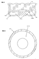
- FIG. 2A is a cross-sectional view in the height direction of the cylindrical sealed battery according to Example 1 and Example 2, and is a cross-sectional view of the main part around the bottom of the outer container before constricting the lower part of the opening of the outer container. It is the top view which looked at the bottom face from the opening side of the exterior container used for Example 1 and Example 2.
- FIG. 3A is a cross-sectional view in the height direction of the cylindrical sealed battery according to Example 3 and Example 4, and is a cross-sectional view of a main part around the bottom of the outer container before the constriction is inserted into the lower part of the outer container opening.
- FIG. 4A is a cross-sectional view in the height direction of the cylindrical sealed battery according to Comparative Example 1, Comparative Example 2, and Comparative Example 3, and is a cross-sectional view of the main part around the bottom of the outer container before constricting the lower part of the outer container opening.
- FIG. 4B is a plan view of the outer container used in Comparative Example 1, Comparative Example 2, and Comparative Example 3 as viewed from the opening side.
- Example 5 is a cross-sectional view in the height direction of the cylindrical sealed battery according to Comparative Example 4 and Comparative Example 5, and is a cross-sectional view of the main part around the bottom of the outer container before the constriction is placed in the lower part of the outer container opening. It is a height direction cross section of the cylindrical sealed battery which concerns on Example 1 and Example 2, Comprising: It is principal part sectional drawing of the exterior container bottom part periphery, The exterior container bottom part periphery after putting a constriction in the exterior container opening lower part It is principal part sectional drawing.
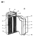
- FIG. 1 is a perspective view showing a cylindrical nonaqueous electrolyte secondary battery manufactured in the embodiment cut in the vertical direction.
- the non-aqueous electrolyte secondary battery 10 of the example uses a winding body 14 in which a positive electrode plate 11 and a negative electrode plate 12 are wound in a spiral shape with a separator 13 interposed therebetween.
- Insulation plates 15 and 16 are arranged on the upper and lower sides of the wound body 14, respectively, and are housed in an iron outer case 17 having a bottomed cylindrical shape and nickel-plated on the surface.
- the electrode tab 12a of the negative electrode plate 12 is welded to the inner bottom of the outer can 17, and the electrode tab 11a of the positive electrode plate 11 is equipped with a safety valve 18 and is welded to the bottom of the sealing body 19 serving as a positive electrode terminal.
- a non-aqueous electrolyte (not shown) is injected into the outer can 17, and the opening of the outer can 17 is sealed with a sealing body 19 via a gasket 21.
- the method for producing the non-aqueous electrolyte secondary battery is as follows.
- ⁇ Preparation of positive electrode plate> 94: 3: 3 (mass ratio) of positive electrode active material in which nickel manganese lithium cobaltate and lithium cobaltate were mixed at a mass ratio of 1: 9, carbon black as a conductive agent, and polyvinylidene fluoride as a binder.
- the mixture was dispersed in N-methyl-2-pyrrolidone to obtain a paste.
- This paste was uniformly applied to both sides of a 15 ⁇ m thick aluminum foil by a doctor blade method and dried by heating to produce a dry electrode plate having an active material layer formed on the aluminum foil.
- the dried electrode plate was compressed to a thickness of 0.13 mm with a roller press, and the width and length were cut into predetermined dimensions, and then the electrode tab 11a was attached to produce the positive electrode plate 11.
- Graphite as a negative electrode active material, styrene butadiene rubber as a binder, and carboxymethyl cellulose as a viscosity modifier were mixed at 96: 2: 2 (mass ratio), and the mixture was dispersed in water to obtain a paste.
- This paste was uniformly applied to both surfaces of a 10 ⁇ m thick copper foil by a doctor blade method and dried by heating to produce a dry electrode plate having an active material layer formed on the copper foil.
- the dried electrode plate was compressed to a thickness of 0.12 mm with a roller press, and the width and length were cut into predetermined dimensions, and then the electrode tab 12a was attached to produce the negative electrode plate 12.
- a winding body winds the said positive electrode plate 11, the negative electrode plate 12, and the polyethylene microporous separator 13 using a winding machine so that the positive electrode plate 11 and the negative electrode plate 12 may be insulated by the separator 13.
- FIG. Produced.
- Lithium hexafluorophosphate as an electrolyte salt was dissolved in an amount of 1.2 mol / liter in a non-aqueous solvent in which ethylene carbonate and ethyl methyl carbonate were mixed at a volume ratio of 30:70 (25 ° C., 1 atm).
- An electrolyte was prepared by dissolving vinylene carbonate in an amount of 2% by mass as an additive.
- ⁇ Preparation of exterior container> A steel plate having a thickness of 0.3 mm was cut out to a predetermined area. And the circumferential recessed part was formed in the part used as the battery inner side bottom face of the exterior container of the cut-out steel plate by forging. Thereafter, the outer container 17 was formed by performing DI processing using a punch and a die to form the shape of the outer container and trimming it to a predetermined height. The material thickness of the bottom surface of the outer container other than the recesses was 0.3 mm. The recess on the bottom surface of the outer container may be processed by cutting the bottom after forming the shape of the outer container.
- ⁇ Battery assembly> The insulating plate 16 was attached to the wound body 14 and stored in the outer container 17, and the negative electrode plate electrode tab 12 a was welded to the inner can bottom of the outer container 17. Then, the insulating plate 15 was attached to the upper part of the winding body 14, a circumferential constriction 22 was formed in the lower part of the opening of the outer container 17, and the gasket 21 was placed on the constriction 22. Further, the positive electrode tab 11 a was welded to the bottom of the sealing body 19.
- a cylindrical nonaqueous electrolyte secondary battery (diameter 18 mm, height 65 mm).
- Example 1 In the cylindrical non-aqueous electrolyte secondary battery, as shown in FIGS. 2A and 2B, the bottom surface on the inner side of the outer container has an inner diameter of 10 mm, an outer diameter of 17.5 mm, and a depth centered on the center point of the outer container bottom surface.
- a recess 171 was formed to be 0.2 mm.
- the width of the positive electrode plate was 55.7 mm, and the width of the negative electrode plate was 57.7 mm.
- the electrode width and the separator width are wider by 0.2 mm than the electrode width of Comparative Example 1 described later. Further, as shown in FIG.
- the negative electrode tab 12a is led out from the outermost periphery of the winding body 14 to the bottom surface of the outer container and bent toward the center of the outer container at a position facing the concave portion of the bottom of the outer container (bent portion 121). Spot welding was performed at the center of the bottom of the outer container.
- the battery thus produced was referred to as Example 1.
- Example 2 In Example 1, it was the same except that the width of the positive electrode plate was 55.9 mm and the width of the negative electrode plate was 57.9 mm. This electrode width is 0.4 mm wider than the electrode width of Comparative Example 1 described later. The battery thus produced was referred to as Example 2.
- Example 3 In the cylindrical non-aqueous electrolyte secondary battery, as shown in FIGS. 3A and 3B, the bottom surface on the inner side of the outer container has an inner diameter of 10 mm, an outer diameter of 14 mm, and a depth of 0 centered on the center point of the outer container bottom surface. A recess was formed to be 2 mm. The width of the positive electrode plate was 55.7 mm, and the width of the negative electrode plate was 57.7 mm. This electrode width is wider by 0.2 mm than the electrode width and separator width of Comparative Example 1 described later. Further, as shown in FIG.
- the negative electrode tab 12a is led out from the middle of winding of the winding body 14 to the bottom surface of the outer container, and toward the center of the outer container at a position (bent portion 121) facing the concave portion at the bottom of the outer container. Bend and spot welded at the center of the bottom of the outer container.
- the battery thus manufactured was referred to as Example 3.
- Example 4 In Example 3, it was the same except that the width of the positive electrode plate was 55.9 mm and the width of the negative electrode plate was 57.9 mm. This electrode width is wider by 0.4 mm than the electrode width and separator width of Comparative Example 1 described later. The battery thus produced was referred to as Example 4.
- Comparative Example 1 As shown in FIGS. 4A and 4B, no recess was provided on the bottom surface of the outer container, the width of the positive electrode plate was 55.5 mm, the width of the negative electrode plate was 57.5 mm, and the width of the separator was 59.5 mm.
- the negative electrode tab 12a was led out from the outermost periphery of the wound body to the bottom surface of the outer container, bent at the bent portion 121 toward the center of the outer surface of the outer container, and spot welded at the center of the bottom surface of the outer container.
- the battery thus produced was designated as Comparative Example 1.
- Comparative Example 2 In Comparative Example 1, it was the same except that the width of the positive electrode plate was 55.7 mm and the width of the negative electrode plate was 57.7 mm. This electrode width is wider by 0.2 mm than the electrode width and separator width of Comparative Example 1. The battery thus produced was referred to as Comparative Example 2.
- Comparative Example 3 In Comparative Example 1, it was the same except that the width of the positive electrode plate was 55.9 mm and the width of the negative electrode plate was 57.9 mm. This electrode width is wider by 0.4 mm than the electrode width and separator width of Comparative Example 1. The battery thus produced was designated as Comparative Example 3.
- Comparative Example 4 In the battery of Example 3, as shown in FIG. 5, the negative electrode tab 12a is led out from the outermost periphery of the winding body 14 to the bottom surface of the outer container, bent at the bent portion 121 toward the center of the outer container, and the center of the bottom surface of the outer container Spot welded. The battery thus produced was designated as Comparative Example 4. Comparative Example 4 is different from Example 3 in that the negative electrode tab 12a is bent at a position that does not face the recess on the bottom surface of the outer container.
- Comparative Example 5 In the battery of Example 4, the negative electrode tab was led out from the outermost periphery of the wound body to the bottom of the outer container and welded. The battery thus produced was designated as Comparative Example 5. Comparative Example 5 is different from Example 4 in that the negative electrode tab 12a is bent at a position that does not face the recess on the bottom surface of the outer container.
- Table 1 shows the battery specifications and test results of the above Examples and Comparative Examples.
- the width of the positive electrode plate / negative electrode plate is The number of batteries in which excessive bending of the negative electrode tab and bending of the electrode of the winding body were observed even when the size was increased, were significantly smaller than in Comparative Examples 1 to 3.
- the depth of the concave portion on the bottom surface of the outer container is 25% or more, more preferably 30% or more, and 80% or less, more preferably 60% or less, of the material thickness of the outer container bottom. If the recess is made too deep, the thickness of the bottom surface of the outer container becomes too thin, which may cause a problem of strength. If there is an excessively large recess on the bottom surface of the outer container, the material thickness of the recess becomes thin, which may cause a problem of strength and hole opening in welding. Therefore, it is not preferable to make the concave portion excessively larger than necessary.
- the recess is formed so that the winding body may be rotated and the electrode tab may be led to any position on the circumference of the bottom surface of the outer container. It is preferably formed in a circumferential shape (doughnut shape).
- Nonaqueous electrolyte secondary battery 11 Positive electrode plate 11a Positive electrode tab 12 Negative electrode plate 12a Negative electrode tab 121
- the bending part of the electrode tab to the center of the exterior container 122 Excessive bending of the electrode tab 13 Separator 14 Winding bodies 15, 16 Insulating plate 17 Exterior container 171 Recess 18 Safety valve 19 Sealing body 21 Gasket 22 Neck
Landscapes
- Chemical & Material Sciences (AREA)
- Chemical Kinetics & Catalysis (AREA)
- Electrochemistry (AREA)
- General Chemical & Material Sciences (AREA)
- Secondary Cells (AREA)
- Sealing Battery Cases Or Jackets (AREA)
Abstract
【課題】高容量で高信頼性の非水電解質二次電池を提供する。 【解決手段】 正極板と負極板がセパレータを介して巻回してなる巻き取り体と、電解質と、を円筒形有底外装容器の中に封入した円筒形密閉電池であって、巻き取り体からは有底外装容器の底面方向に正極板または負極板のいずれかに接続される電極タブが突出し、電極タブは巻き取り体と外装容器内側の底面との間で屈曲部を有して外装容器の底面に接続されており、外装容器は電極タブの屈曲部と対向する底面に凹部を有する構成とする。
Description
本発明は信頼性を向上した円筒形密閉電池に関する。
リチウムイオン電池に代表される非水電解質二次電池やニッケル水素電池に代表されるアルカリ蓄電池は、高エネルギー密度を特徴とすることから、携帯機器などの電源のみならず、電動工具や電気自動車、電力貯蔵などの電源にも、その用途を拡大している。
そのような電池のなかで例えばリチウムイオン電池は、正極活物質として、リチウムイオンを可逆的に吸蔵放出可能なコバルト酸リチウム、ニッケル酸リチウム、マンガン酸リチウムなど、リチウム遷移金属酸化物が用いられる。そして正極活物質は結着剤や導電剤等と混合され、アルミニウム箔上に塗布されて正極板として用いられる。
一方、負極活物質としては、天然黒鉛、人造黒鉛、コークスなどの炭素質材料やシリコンや錫とそれらの合金、酸化物等が用いられる。そして負極活物質は結着剤等と混合され、銅箔上に塗布されて負極板として用いられる。
正極板と負極板は所定の寸法に加工されて、樹脂製微多孔セパレータを介して円筒状に巻き取られて巻き取り体をなし、電解質とともに円筒状の外装容器へ封入される。
ところで、円筒形密閉電池や角形密閉電池には有底の円筒形状や直方体形状であって、1か所の開口を備える金属製の有底外装容器が多く用いられる。そのような外装容器は、種々の目的で表面や内面に凹凸が設けられることがある。
例えば特許文献1には、機器に収納された電池を狭いスペースから取り出し易くするために、外装容器の底にネイルフックとなる凹部や凸部を設けた電池が開示されている。また、特許文献2には、電池反応に必要な電解液を外装容器内に保持するために、電池内部の缶底に凹部を設けた電池が開示されている。
種々の機器の電源となる電池は、高容量でかつ高信頼性であることが絶えず要求されている。高容量の電池を製造するため、限られた外装容器体積内で電池反応に関与しない部分をできる限り排除し、できるだけ多くの活物質を仕込むことが考えられる。そのためには、外装容器の金属材料の厚さを薄くしたり、電極の活物質密度を高めたり、電極幅を大きくすることが行われる。
しかし、外装容器材料の厚さを薄くすると、電池をパック電池等に加工する場面で、外装容器に溶接を行うと外装容器に穴が開いてそこから電解液が漏出することが生じうる。また、電極の密度を高めると電解液が電極に浸透しにくくなる。
また、電極幅を大きくして電池容量を高くすると両電極を絶縁するセパレータの幅も大きくするので巻き取り体の高さが大きくなり、例えば巻き取り体を外装容器に収納して製造する電池においては、以下の不具合が生じ得る。すなわち、巻き取り体から導出される電極タブは外装容器の底面付近で屈曲されて溶接される。そして外装容器の開口は封口体を用いて封止される。封口体を外装容器の開口にかしめ付けるために、巻き取り体を外装容器に収納後、外装容器の開口の下方にくびれを設けるが、このとき巻き取り体を上方から底面方向に押さえることになるので、電極タブが屈曲部分付近で余分な屈曲を生じ得る。その余分な電極タブの屈曲の影響で巻き取り体の電極も屈曲し、短絡の原因となり得る。外装容器にくびれを設けない電池であっても、外装容器の高さは一定であるので、電極板の幅を大きくすると同様の課題が生じうる。
本発明はこのような課題を鑑みてなされたものであり、その目的は信頼性を維持しながら高容量とした円筒形密閉電池を提供することである。
上記課題を解決するための本発明に係る第一の態様の円筒形密閉電池は、正極板と負極板がセパレータを介して巻回してなる巻き取り体と、電解質とを円筒形外装容器の中に封入した円筒形密閉電池であって、巻き取り体からは有底外装容器の底面方向に正極板または負極板のいずれかに接続される電極タブが突出し、電極タブは巻き取り体と外装容器内側の底面との間で屈曲部を有して外装容器の底面に接続されており、外装容器は電極タブの屈曲部と対向する底面に凹部を有することを特徴とする。
円筒形密閉電池を上記の構成とすることで、巻き取り体が電池上部から外装容器底面方向に押されても、電極タブが余分な屈曲を生じずに外装容器の凹部に移動できる。そのため、巻き取り体の電極の屈曲も生じず、短絡が防止できる。
また本発明に係る第二の態様の円筒形密閉電池は、外装容器外側の底面は平坦であることを特徴とする。
円筒形密閉電池を上記の構成とすることで、電池を製造した後にパック電池を組み立てる場面で、外装容器外側の底面に外部回路等と接続するリードを溶接するが、外装容器の底面が平面であるので溶接が容易になる。
さらに、本発明に係る第三の態様の円筒形密閉電池は、外装容器底部の凹部における外装容器材料厚さが0.1mm以上であることを特徴とする。
外装容器の底部の材料厚さを厚くすると外装容器の強度は増すが、電池反応に直接関与しない体積が増加するので電池容量やエネルギー密度が小さくなる。しかし、外装容器の底部の材料厚さを薄くしすぎると外装容器の強度が低下する。そこで外装容器の底部の凹部における外装容器材料厚さが0.1mm以上とすることで外装容器に必要な強度を維持できるので好ましい。このとき、凹部の深さは0.05~0.40mmとすることで、余分な電極タブの屈曲を生じず、電池容量を大きくすることができるので好ましい。
さらに、本発明に係る第四の態様の円筒形密閉電池は、外装容器底部の凹部以外の外装容器の材料厚さが0.2~0.5mmであることを特徴とする。
外装容器底部の凹部以外の部分は電極タブや外部回路へのリードなどが溶接される。このとき外装容器の材料厚さが薄すぎると、溶接の際に外装容器に穴が開き、電解質漏出の原因となる。外装容器材料厚さが厚すぎると電池容量やエネルギー密度が小さくなる。したがって、外装容器材料厚さは0.2~0.5mmが好ましい。
本発明によると、巻き取り体が外装容器に収納され、外装容器上方より底部方向へ押されても、巻き取り体から導出される電極タブに余分な屈曲が生じず、巻き取り体の電極の屈曲が生じないので短絡が防止できる。したがって、信頼性が高く、電池容量の高い円筒形密閉電池が提供できる。
本発明を実施するための形態を、非水電解質二次電池を例として、図面に基づいて説明する。なお、本発明は下記の形態に限定されるものではなく、その要旨を変更しない範囲において適宜変更して実施することが可能である。
図1は実施形態で製造した円筒形の非水電解質二次電池を縦方向に切断して示す斜視図である。
[実施の形態]
実施例の非水電解質二次電池10は、図1に示したように、正極板11と負極板12とがセパレータ13を介して渦巻き状に巻回した巻き取り体14が用いられている。巻き取り体14は、上下にそれぞれ絶縁板15、16が配置され、有底円筒形であって表面にニッケルメッキが施された鉄製外装容器17の内部に収容されている。負極板12の電極タブ12aは外装缶17の内側底部に溶接され、正極板11の電極タブ11aは、安全弁18を備え、正極端子となる封口体19の底に溶接されている。そして、外装缶17の内部には図示しない非水電解質が注入されており、外装缶17の開口部はガスケット21を介して封口体19で密閉されている。
実施例の非水電解質二次電池10は、図1に示したように、正極板11と負極板12とがセパレータ13を介して渦巻き状に巻回した巻き取り体14が用いられている。巻き取り体14は、上下にそれぞれ絶縁板15、16が配置され、有底円筒形であって表面にニッケルメッキが施された鉄製外装容器17の内部に収容されている。負極板12の電極タブ12aは外装缶17の内側底部に溶接され、正極板11の電極タブ11aは、安全弁18を備え、正極端子となる封口体19の底に溶接されている。そして、外装缶17の内部には図示しない非水電解質が注入されており、外装缶17の開口部はガスケット21を介して封口体19で密閉されている。
上記非水電解質二次電池の作製方法は以下のとおりである。
<正極板の作製>
ニッケルマンガンコバルト酸リチウムとコバルト酸リチウムを質量比で1:9の割合で混合した正極活物質と、導電剤としてカーボンブラックと、結着剤としてポリフッ化ビニリデンとを94:3:3(質量比)で混合し、この混合物をN-メチル-2-ピロリドンに分散してペーストとした。このペーストをドクターブレード法により、厚さ15μmのアルミニウム箔の両面に均一に塗布し、加熱乾燥して、アルミニウム箔上に活物質層が形成された乾燥極板を作製した。乾燥極板をローラープレス機で厚さ0.13mmになるように圧縮し、幅と長さを所定寸法に裁断後、電極タブ11aを取り付けて正極板11を作製した。
ニッケルマンガンコバルト酸リチウムとコバルト酸リチウムを質量比で1:9の割合で混合した正極活物質と、導電剤としてカーボンブラックと、結着剤としてポリフッ化ビニリデンとを94:3:3(質量比)で混合し、この混合物をN-メチル-2-ピロリドンに分散してペーストとした。このペーストをドクターブレード法により、厚さ15μmのアルミニウム箔の両面に均一に塗布し、加熱乾燥して、アルミニウム箔上に活物質層が形成された乾燥極板を作製した。乾燥極板をローラープレス機で厚さ0.13mmになるように圧縮し、幅と長さを所定寸法に裁断後、電極タブ11aを取り付けて正極板11を作製した。
<負極板の作製>
負極活物質として黒鉛と、結着剤としてスチレンブタジエンゴムと、粘度調整剤としてカルボキシメチルセルロースとを96:2:2(質量比)で混合し、この混合物を水に分散してペーストとした。このペーストをドクターブレード法により、厚さ10μmの銅箔の両面に均一に塗布し、加熱乾燥して、銅箔上に活物質層が形成された乾燥極板を作製した。乾燥極板をローラープレス機で厚さ0.12mmになるように圧縮し、幅と長さを所定寸法に裁断後、電極タブ12aを取り付けて負極板12を作製した。
負極活物質として黒鉛と、結着剤としてスチレンブタジエンゴムと、粘度調整剤としてカルボキシメチルセルロースとを96:2:2(質量比)で混合し、この混合物を水に分散してペーストとした。このペーストをドクターブレード法により、厚さ10μmの銅箔の両面に均一に塗布し、加熱乾燥して、銅箔上に活物質層が形成された乾燥極板を作製した。乾燥極板をローラープレス機で厚さ0.12mmになるように圧縮し、幅と長さを所定寸法に裁断後、電極タブ12aを取り付けて負極板12を作製した。
<巻き取り体の作製>
巻き取り体は、上記正極板11と負極板12とポリエチレン製微多孔質セパレータ13とを、正極板11と負極板12がセパレータ13により絶縁されるように、巻き取り機を用いて巻回して作製した。
巻き取り体は、上記正極板11と負極板12とポリエチレン製微多孔質セパレータ13とを、正極板11と負極板12がセパレータ13により絶縁されるように、巻き取り機を用いて巻回して作製した。
<電解質の作製>
エチレンカーボネートとエチルメチルカーボネートを体積比で30:70(25℃、1気圧)の割合で混合した非水溶媒に電解質塩として六フッ化リン酸リチウムを1.2モル/リットル溶解した。これに添加剤としてビニレンカーボネートを2質量%の割合で溶解して電解質を作製した。
エチレンカーボネートとエチルメチルカーボネートを体積比で30:70(25℃、1気圧)の割合で混合した非水溶媒に電解質塩として六フッ化リン酸リチウムを1.2モル/リットル溶解した。これに添加剤としてビニレンカーボネートを2質量%の割合で溶解して電解質を作製した。
<外装容器の作製>
厚さ0.3mmの鋼板を所定の面積に切り抜いた。そして切り抜いた鋼板の外装容器の電池内部側底面になる部分に鍛造にて円周状の凹部を形成した。その後、パンチとダイを用いてDI加工を行うことで外装容器の形状を形成し、所定高さとなるようにトリミングすることで外装容器17を作製した。凹部以外の外装容器底面の材料厚さは0.3mmとした。なお外装容器底面の凹部は、外装容器形状を形成した後に底部を切削して加工してもよい。
厚さ0.3mmの鋼板を所定の面積に切り抜いた。そして切り抜いた鋼板の外装容器の電池内部側底面になる部分に鍛造にて円周状の凹部を形成した。その後、パンチとダイを用いてDI加工を行うことで外装容器の形状を形成し、所定高さとなるようにトリミングすることで外装容器17を作製した。凹部以外の外装容器底面の材料厚さは0.3mmとした。なお外装容器底面の凹部は、外装容器形状を形成した後に底部を切削して加工してもよい。
<電池の組み立て>
上記巻き取り体14に絶縁板16を取り付けて外装容器17に収納し、負極板電極タブ12aを外装容器17の内側缶底に溶接した。そして巻き取り体14の上部に絶縁板15を取り付け、外装容器17開口の下部に周状のくびれ22を形成し、くびれ22の上にガスケット21を載置した。さらに正極板電極タブ11aを封口体19の底に溶接した。そして上記電解質を外装缶17に所定量注入した後、外装容器17の開口を封口体19で密閉して、円筒形非水電解質二次電池(直径18mm、高さ65mm)を作製した。
上記巻き取り体14に絶縁板16を取り付けて外装容器17に収納し、負極板電極タブ12aを外装容器17の内側缶底に溶接した。そして巻き取り体14の上部に絶縁板15を取り付け、外装容器17開口の下部に周状のくびれ22を形成し、くびれ22の上にガスケット21を載置した。さらに正極板電極タブ11aを封口体19の底に溶接した。そして上記電解質を外装缶17に所定量注入した後、外装容器17の開口を封口体19で密閉して、円筒形非水電解質二次電池(直径18mm、高さ65mm)を作製した。
以上の非水電解質二次電池の作製方法を基本として、以下に述べる実施例と比較例の電池を作製した。
(実施例1)
上記円筒形非水電解質二次電池において、図2A、図2Bに示すように外装容器の内部側の底面に、外装容器底面の中心点を中心とする内径10mm、外径17.5mm、深さ0.2mmとなるように凹部171を形成した。また、正極板の幅を55.7mm、負極板の幅を57.7mmとした。この電極幅、セパレータ幅は、後述する比較例1の電極幅と比較して0.2mmだけ幅広となる。また図2Aに示されるように、負極電極タブ12aを巻き取り体14の最外周から外装容器底面へ導出し外装容器底部の凹部に対向した位置(屈曲部121)で外装容器中心方向へ曲げ、外装容器底面の中心でスポット溶接した。このように作製した電池を実施例1とした。
上記円筒形非水電解質二次電池において、図2A、図2Bに示すように外装容器の内部側の底面に、外装容器底面の中心点を中心とする内径10mm、外径17.5mm、深さ0.2mmとなるように凹部171を形成した。また、正極板の幅を55.7mm、負極板の幅を57.7mmとした。この電極幅、セパレータ幅は、後述する比較例1の電極幅と比較して0.2mmだけ幅広となる。また図2Aに示されるように、負極電極タブ12aを巻き取り体14の最外周から外装容器底面へ導出し外装容器底部の凹部に対向した位置(屈曲部121)で外装容器中心方向へ曲げ、外装容器底面の中心でスポット溶接した。このように作製した電池を実施例1とした。
(実施例2)
実施例1において、正極板の幅を55.9mm、負極板の幅を57.9mmとした以外は同様とした。この電極幅は、後述する比較例1の電極幅と比較して0.4mmだけ幅広となる。このように作製した電池を実施例2とした。
実施例1において、正極板の幅を55.9mm、負極板の幅を57.9mmとした以外は同様とした。この電極幅は、後述する比較例1の電極幅と比較して0.4mmだけ幅広となる。このように作製した電池を実施例2とした。
(実施例3)
上記円筒形非水電解質二次電池において、図3A、図3Bに示すように、外装容器の内部側の底面に、外装容器底面の中心点を中心とする内径10mm、外径14mm、深さ0.2mmとなるように凹部を形成した。また、正極板の幅を55.7mm、負極板の幅を57.7mmとした。この電極幅は、後述する比較例1の電極幅、セパレータ幅と比較して0.2mmだけ幅広となる。また図3Aに示されるように、負極電極タブ12aを巻き取り体14の巻回途中から外装容器底面へ導出し、外装容器底部の凹部に対向した位置(屈曲部121)で外装容器中心方向へ曲げ、外装容器底面の中心でスポット溶接した。このように作製した電池を実施例3とした。
上記円筒形非水電解質二次電池において、図3A、図3Bに示すように、外装容器の内部側の底面に、外装容器底面の中心点を中心とする内径10mm、外径14mm、深さ0.2mmとなるように凹部を形成した。また、正極板の幅を55.7mm、負極板の幅を57.7mmとした。この電極幅は、後述する比較例1の電極幅、セパレータ幅と比較して0.2mmだけ幅広となる。また図3Aに示されるように、負極電極タブ12aを巻き取り体14の巻回途中から外装容器底面へ導出し、外装容器底部の凹部に対向した位置(屈曲部121)で外装容器中心方向へ曲げ、外装容器底面の中心でスポット溶接した。このように作製した電池を実施例3とした。
(実施例4)
実施例3において、正極板の幅を55.9mm、負極板の幅を57.9mmとした以外は同様とした。この電極幅は、後述する比較例1の電極幅、セパレータ幅と比較して0.4mmだけ幅広となる。このように作製した電池を実施例4とした。
実施例3において、正極板の幅を55.9mm、負極板の幅を57.9mmとした以外は同様とした。この電極幅は、後述する比較例1の電極幅、セパレータ幅と比較して0.4mmだけ幅広となる。このように作製した電池を実施例4とした。
(比較例1)
図4A、図4Bに示すように、外装容器底面に凹部を設けず、正極板の幅を55.5mm、負極板の幅を57.5mm、セパレータの幅を59.5mmとした。また、負極電極タブ12aを巻き取り体の最外周から外装容器底面へ導出し、屈曲部121で外装容器底面中心方向へ曲げ、外装容器底面の中心でスポット溶接した。このように作製した電池を比較例1とした。
図4A、図4Bに示すように、外装容器底面に凹部を設けず、正極板の幅を55.5mm、負極板の幅を57.5mm、セパレータの幅を59.5mmとした。また、負極電極タブ12aを巻き取り体の最外周から外装容器底面へ導出し、屈曲部121で外装容器底面中心方向へ曲げ、外装容器底面の中心でスポット溶接した。このように作製した電池を比較例1とした。
(比較例2)
比較例1において、正極板の幅を55.7mm、負極板の幅を57.7mmとした以外は同様とした。この電極幅は、比較例1の電極幅、セパレータ幅と比較して0.2mmだけ幅広となる。このように作製した電池を比較例2とした。
比較例1において、正極板の幅を55.7mm、負極板の幅を57.7mmとした以外は同様とした。この電極幅は、比較例1の電極幅、セパレータ幅と比較して0.2mmだけ幅広となる。このように作製した電池を比較例2とした。
(比較例3)
比較例1において、正極板の幅を55.9mm、負極板の幅を57.9mmとした以外は同様とした。この電極幅は、比較例1の電極幅、セパレータ幅と比較して0.4mmだけ幅広となる。このように作製した電池を比較例3とした。
比較例1において、正極板の幅を55.9mm、負極板の幅を57.9mmとした以外は同様とした。この電極幅は、比較例1の電極幅、セパレータ幅と比較して0.4mmだけ幅広となる。このように作製した電池を比較例3とした。
(比較例4)
実施例3の電池において、図5に示すように、負極電極タブ12aを巻き取り体14の最外周から外装容器底面へ導出し、屈曲部121で外装容器中心方向へ曲げ、外装容器底面の中心でスポット溶接した。このように作製した電池を比較例4とした。比較例4は、負極電極タブ12aが外装容器底面の凹部とは対向しない位置で曲げられている点で実施例3とは異なる。
実施例3の電池において、図5に示すように、負極電極タブ12aを巻き取り体14の最外周から外装容器底面へ導出し、屈曲部121で外装容器中心方向へ曲げ、外装容器底面の中心でスポット溶接した。このように作製した電池を比較例4とした。比較例4は、負極電極タブ12aが外装容器底面の凹部とは対向しない位置で曲げられている点で実施例3とは異なる。
(比較例5)
実施例4の電池において、負極電極タブを巻き取り体の最外周から外装容器底部へ導出して溶接した。このように作製した電池を比較例5とした。比較例5は、負極電極タブ12aが外装容器底面の凹部とは対向しない位置で曲げられている点で実施例4とは異なる。
実施例4の電池において、負極電極タブを巻き取り体の最外周から外装容器底部へ導出して溶接した。このように作製した電池を比較例5とした。比較例5は、負極電極タブ12aが外装容器底面の凹部とは対向しない位置で曲げられている点で実施例4とは異なる。
(負極電極タブの状態観察)
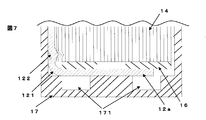
作製した各電池の外装容器底部近傍の負極電極タブの状態や巻き取り体の電極の状態を、X線透過検査機を用いて観察した。図6のように負極電極タブの外装容器底面の中心への屈曲部121以外に余分な折れ曲がりが観察されないものを良品とし、図7のように屈曲部121以外に負極電極タブの余分な屈曲122が生じて巻き取り体の極板が変形しているものを不良品と判定した。観察は各30個の電池について行った。
作製した各電池の外装容器底部近傍の負極電極タブの状態や巻き取り体の電極の状態を、X線透過検査機を用いて観察した。図6のように負極電極タブの外装容器底面の中心への屈曲部121以外に余分な折れ曲がりが観察されないものを良品とし、図7のように屈曲部121以外に負極電極タブの余分な屈曲122が生じて巻き取り体の極板が変形しているものを不良品と判定した。観察は各30個の電池について行った。
上記の各実施例および各比較例の電池仕様と試験結果を表1に示す。

上記表1から、以下のことが判る。すなわち、外装容器底面に凹部を設けない比較例1~3は、正極板・負極板の幅が大きくなるにしたがい、負極電極タブの余分な屈曲や巻き取り体の電極の折れ曲がりが観察された電池数が増加した。
一方、外装容器底面に凹部を設け、負極電極タブの外装容器底面の中心への屈曲が外装容器底部の凹部に対向している実施例1~4の電池では、正極板・負極板の幅が大きくなっても負極電極タブの余分な屈曲や巻き取り体の電極の折れ曲がりが観察された電池数が、比較例1~3と比べて大幅に少なくなっている。
このことは、以下のように考えられる。すなわち、電池製造にあたり外装容器開口を封止するための封口体をかしめ付ける前に、外装容器へ巻き取り体収納後、外装容器開口下部にくびれを設ける。このくびれを設けるときに巻き取り体が外装容器下方に押される。この時、巻き取り体の電極に固定された電極タブも外装容器下方に押されるが、外装容器底部では押された電極タブの逃げ場がないと余分に折れ曲がる。このように外装容器底面に凹部がない比較例1~3は、上方から押された電極タブの逃げ場がなく余分に屈曲し、電極板の幅が大きくなるにつれて、その度合いが大きくなったものと考えられる。
一方、電極タブが外装容器中心へ屈曲する位置と対向する外装容器底面に凹部があると、凹部で電極タブが上方より押された部分を吸収するので、電極タブは余分に屈曲しにくくなる。よって、電極板の幅が大きくなっても電極タブの余分な屈曲や巻き取り体の電極の折れ曲がりを防止することができる。
しかし比較例4、5のように、外装容器底面に凹部があっても、その位置と電極タブの位置が対向していないと、巻き取り体が外装容器下方に押されても電極タブの逃げ場がない。したがって、比較例1~3と同様に電極板の幅が大きくなるにつれて電極タブの余分な屈曲や巻き取り体の電極の折れ曲がりの発生度合いが大きくなると考えられる。
このような外装容器底面の凹部の深さは、外装容器底部の材料厚さの25%以上、より好ましくは30%以上であって、80%以下、より好ましくは60%以下とする。あまり凹部を深くすると外装容器底面の肉厚が薄くなりすぎて強度の問題を生じる可能性がある。外装容器底面に過度に大きい凹部があると、凹部は材料厚さが肉薄になるので、強度や溶接での穴開きの問題が生じる可能性がある。したがって、凹部は必要以上に過度に大きい凹部を大きくすることは好ましくない。また、巻き取り体の巻回軸に垂直な断面は円形状であるので、巻き取り体が回転して電極タブが外装容器底面の円周上どの位置に導出されても良いように、凹部は円周状(ドーナッツ状)に形成されることが好ましい。
以上説明したように、本発明によれば、電極板の幅が大きくなっても電極タブの余分な屈曲が防止でき、電池容量が大きく信頼性の高い非水電解質二次電池を提供できるので、産業上の利用可能性が大きい。
10 非水電解質二次電池
11 正極板
11a 正極電極タブ
12 負極板
12a 負極電極タブ
121 電極タブの外装容器中心への屈曲部
122 電極タブの余分な屈曲
13 セパレータ
14 巻き取り体
15、16 絶縁板
17 外装容器
171 凹部
18 安全弁
19 封口体
21 ガスケット
22 くびれ
11 正極板
11a 正極電極タブ
12 負極板
12a 負極電極タブ
121 電極タブの外装容器中心への屈曲部
122 電極タブの余分な屈曲
13 セパレータ
14 巻き取り体
15、16 絶縁板
17 外装容器
171 凹部
18 安全弁
19 封口体
21 ガスケット
22 くびれ
Claims (4)
- 正極板と負極板がセパレータを介して巻回されてなる巻き取り体と、
電解質と、を円筒形有底外装容器の中に封入した円筒形密閉電池であって、
前記巻き取り体からは前記有底外装容器の底面方向に前記正極板または前記負極板のいずれかに接続される電極タブが突出し、
前記電極タブは前記巻き取り体と前記外装容器内側の底面との間で屈曲部を有して前記外装容器の底面に接続されており、
前記外装容器は、前記電極タブの屈曲部と対向する底面に凹部を有することを特徴とする円筒形密閉電池。 - 前記外装容器外側の底面は平坦であることを特徴とする請求項1に記載の円筒形密閉電池。
- 前記外装容器底部の凹部における前記外装容器材料厚さが0.1mm以上であることを特徴とする請求項1または2に記載の円筒形密閉電池。
- 前記外装容器底部の凹部以外の前記外装容器材料厚さが0.2~0.5mmであることを特徴とする請求項1から3のいずれかに記載の円筒形密閉電池。
Applications Claiming Priority (2)
| Application Number | Priority Date | Filing Date | Title |
|---|---|---|---|
| JP2011-017727 | 2011-01-31 | ||
| JP2011017727 | 2011-01-31 |
Publications (1)
| Publication Number | Publication Date |
|---|---|
| WO2012105363A1 true WO2012105363A1 (ja) | 2012-08-09 |
Family
ID=46602582
Family Applications (1)
| Application Number | Title | Priority Date | Filing Date |
|---|---|---|---|
| PCT/JP2012/051398 Ceased WO2012105363A1 (ja) | 2011-01-31 | 2012-01-24 | 円筒形密閉電池 |
Country Status (1)
| Country | Link |
|---|---|
| WO (1) | WO2012105363A1 (ja) |
Cited By (1)
| Publication number | Priority date | Publication date | Assignee | Title |
|---|---|---|---|---|
| WO2026070615A1 (ja) * | 2024-09-24 | 2026-04-02 | パナソニックIpマネジメント株式会社 | 二次電池及び二次電池の製造方法 |
Citations (6)
| Publication number | Priority date | Publication date | Assignee | Title |
|---|---|---|---|---|
| JPH09306503A (ja) * | 1996-05-16 | 1997-11-28 | Hitachi Maxell Ltd | リチウム二次電池 |
| JP2003257380A (ja) * | 2002-03-04 | 2003-09-12 | Matsushita Electric Ind Co Ltd | 電 池 |
| JP2005123197A (ja) * | 2003-10-15 | 2005-05-12 | Samsung Sdi Co Ltd | 二次電池および二次電池の製造方法 |
| JP2008135273A (ja) * | 2006-11-28 | 2008-06-12 | Sony Corp | 電解液および電池 |
| JP2009032504A (ja) * | 2007-07-26 | 2009-02-12 | Hitachi Vehicle Energy Ltd | 非水電解質二次電池およびその製造方法 |
| JP2010199069A (ja) * | 2009-02-26 | 2010-09-09 | Samsung Sdi Co Ltd | 円筒形二次電池 |
-
2012
- 2012-01-24 WO PCT/JP2012/051398 patent/WO2012105363A1/ja not_active Ceased
Patent Citations (6)
| Publication number | Priority date | Publication date | Assignee | Title |
|---|---|---|---|---|
| JPH09306503A (ja) * | 1996-05-16 | 1997-11-28 | Hitachi Maxell Ltd | リチウム二次電池 |
| JP2003257380A (ja) * | 2002-03-04 | 2003-09-12 | Matsushita Electric Ind Co Ltd | 電 池 |
| JP2005123197A (ja) * | 2003-10-15 | 2005-05-12 | Samsung Sdi Co Ltd | 二次電池および二次電池の製造方法 |
| JP2008135273A (ja) * | 2006-11-28 | 2008-06-12 | Sony Corp | 電解液および電池 |
| JP2009032504A (ja) * | 2007-07-26 | 2009-02-12 | Hitachi Vehicle Energy Ltd | 非水電解質二次電池およびその製造方法 |
| JP2010199069A (ja) * | 2009-02-26 | 2010-09-09 | Samsung Sdi Co Ltd | 円筒形二次電池 |
Cited By (1)
| Publication number | Priority date | Publication date | Assignee | Title |
|---|---|---|---|---|
| WO2026070615A1 (ja) * | 2024-09-24 | 2026-04-02 | パナソニックIpマネジメント株式会社 | 二次電池及び二次電池の製造方法 |
Similar Documents
| Publication | Publication Date | Title |
|---|---|---|
| JP6208687B2 (ja) | 円筒形二次電池及びその製造方法 | |
| JP5737481B2 (ja) | 密閉型非水電解質二次電池 | |
| EP3477729B1 (en) | Rechargeable lithium ion button cell battery | |
| JP3819785B2 (ja) | 集合電池 | |
| JP6801645B2 (ja) | 円筒形電池 | |
| JP5899495B2 (ja) | 円筒形リチウムイオン電池 | |
| WO2018142928A1 (ja) | 二次電池 | |
| US12095074B2 (en) | Nonaqueous electrolyte secondary battery | |
| JP7171585B2 (ja) | 円筒形非水電解質二次電池 | |
| JP2013026123A (ja) | 二次電池および電極板 | |
| JP2002203534A (ja) | 薄型二次電池および電池パック | |
| JP2011233462A (ja) | 電池、電池の製造方法、及び金属シートの接合方法 | |
| WO2022202270A1 (ja) | 円筒形電池 | |
| JP6731580B2 (ja) | 円筒形リチウムイオン二次電池 | |
| JPWO2018088204A1 (ja) | 非水電解質二次電池用電極及び非水電解質二次電池 | |
| JP2016126975A (ja) | 円筒形電池 | |
| JP2018160439A (ja) | 非水電解質二次電池 | |
| US11621450B2 (en) | Battery can and cylindrical battery | |
| CN101847741B (zh) | 密封型电池 | |
| JP2011187241A (ja) | 非水電解質二次電池 | |
| JP2010199029A (ja) | 密閉型電池 | |
| JP4929619B2 (ja) | 円柱状リチウム二次電池 | |
| WO2012105363A1 (ja) | 円筒形密閉電池 | |
| JP2006278184A (ja) | 角型電池及びその製造方法 | |
| JP2014107054A (ja) | 密閉型電池 |
Legal Events
| Date | Code | Title | Description |
|---|---|---|---|
| 121 | Ep: the epo has been informed by wipo that ep was designated in this application |
Ref document number: 12742365 Country of ref document: EP Kind code of ref document: A1 |
|
| NENP | Non-entry into the national phase |
Ref country code: DE |
|
| 122 | Ep: pct application non-entry in european phase |
Ref document number: 12742365 Country of ref document: EP Kind code of ref document: A1 |
|
| NENP | Non-entry into the national phase |
Ref country code: JP |