WO2012111572A1 - Cosse, et fixation pour assemblage de cette cosse - Google Patents
Cosse, et fixation pour assemblage de cette cosse Download PDFInfo
- Publication number
- WO2012111572A1 WO2012111572A1 PCT/JP2012/053171 JP2012053171W WO2012111572A1 WO 2012111572 A1 WO2012111572 A1 WO 2012111572A1 JP 2012053171 W JP2012053171 W JP 2012053171W WO 2012111572 A1 WO2012111572 A1 WO 2012111572A1
- Authority
- WO
- WIPO (PCT)
- Prior art keywords
- female terminal
- connector
- housing
- fitting
- connector housing
- Prior art date
- Legal status (The legal status is an assumption and is not a legal conclusion. Google has not performed a legal analysis and makes no representation as to the accuracy of the status listed.)
- Ceased
Links
Images

Classifications
-
- H—ELECTRICITY
- H01—ELECTRIC ELEMENTS
- H01R—ELECTRICALLY-CONDUCTIVE CONNECTIONS; STRUCTURAL ASSOCIATIONS OF A PLURALITY OF MUTUALLY-INSULATED ELECTRICAL CONNECTING ELEMENTS; COUPLING DEVICES; CURRENT COLLECTORS
- H01R13/00—Details of coupling devices of the kinds covered by groups H01R12/70 or H01R24/00 - H01R33/00
- H01R13/40—Securing contact members in or to a base or case; Insulating of contact members
- H01R13/42—Securing in a demountable manner
- H01R13/436—Securing a plurality of contact members by one locking piece or operation
- H01R13/4361—Insertion of locking piece perpendicular to direction of contact insertion
-
- H—ELECTRICITY
- H01—ELECTRIC ELEMENTS
- H01R—ELECTRICALLY-CONDUCTIVE CONNECTIONS; STRUCTURAL ASSOCIATIONS OF A PLURALITY OF MUTUALLY-INSULATED ELECTRICAL CONNECTING ELEMENTS; COUPLING DEVICES; CURRENT COLLECTORS
- H01R13/00—Details of coupling devices of the kinds covered by groups H01R12/70 or H01R24/00 - H01R33/00
- H01R13/40—Securing contact members in or to a base or case; Insulating of contact members
- H01R13/405—Securing in non-demountable manner, e.g. moulding, riveting
-
- H—ELECTRICITY
- H01—ELECTRIC ELEMENTS
- H01R—ELECTRICALLY-CONDUCTIVE CONNECTIONS; STRUCTURAL ASSOCIATIONS OF A PLURALITY OF MUTUALLY-INSULATED ELECTRICAL CONNECTING ELEMENTS; COUPLING DEVICES; CURRENT COLLECTORS
- H01R43/00—Apparatus or processes specially adapted for manufacturing, assembling, maintaining, or repairing of line connectors or current collectors or for joining electric conductors
- H01R43/20—Apparatus or processes specially adapted for manufacturing, assembling, maintaining, or repairing of line connectors or current collectors or for joining electric conductors for assembling or disassembling contact members with insulating base, case or sleeve
- H01R43/22—Hand tools
-
- H—ELECTRICITY
- H01—ELECTRIC ELEMENTS
- H01R—ELECTRICALLY-CONDUCTIVE CONNECTIONS; STRUCTURAL ASSOCIATIONS OF A PLURALITY OF MUTUALLY-INSULATED ELECTRICAL CONNECTING ELEMENTS; COUPLING DEVICES; CURRENT COLLECTORS
- H01R43/00—Apparatus or processes specially adapted for manufacturing, assembling, maintaining, or repairing of line connectors or current collectors or for joining electric conductors
- H01R43/26—Apparatus or processes specially adapted for manufacturing, assembling, maintaining, or repairing of line connectors or current collectors or for joining electric conductors for engaging or disengaging the two parts of a coupling device
-
- H—ELECTRICITY
- H01—ELECTRIC ELEMENTS
- H01R—ELECTRICALLY-CONDUCTIVE CONNECTIONS; STRUCTURAL ASSOCIATIONS OF A PLURALITY OF MUTUALLY-INSULATED ELECTRICAL CONNECTING ELEMENTS; COUPLING DEVICES; CURRENT COLLECTORS
- H01R4/00—Electrically-conductive connections between two or more conductive members in direct contact, i.e. touching one another; Means for effecting or maintaining such contact; Electrically-conductive connections having two or more spaced connecting locations for conductors and using contact members penetrating insulation
- H01R4/10—Electrically-conductive connections between two or more conductive members in direct contact, i.e. touching one another; Means for effecting or maintaining such contact; Electrically-conductive connections having two or more spaced connecting locations for conductors and using contact members penetrating insulation effected solely by twisting, wrapping, bending, crimping, or other permanent deformation
- H01R4/18—Electrically-conductive connections between two or more conductive members in direct contact, i.e. touching one another; Means for effecting or maintaining such contact; Electrically-conductive connections having two or more spaced connecting locations for conductors and using contact members penetrating insulation effected solely by twisting, wrapping, bending, crimping, or other permanent deformation by crimping
- H01R4/183—Electrically-conductive connections between two or more conductive members in direct contact, i.e. touching one another; Means for effecting or maintaining such contact; Electrically-conductive connections having two or more spaced connecting locations for conductors and using contact members penetrating insulation effected solely by twisting, wrapping, bending, crimping, or other permanent deformation by crimping for cylindrical elongated bodies, e.g. cables having circular cross-section
- H01R4/184—Electrically-conductive connections between two or more conductive members in direct contact, i.e. touching one another; Means for effecting or maintaining such contact; Electrically-conductive connections having two or more spaced connecting locations for conductors and using contact members penetrating insulation effected solely by twisting, wrapping, bending, crimping, or other permanent deformation by crimping for cylindrical elongated bodies, e.g. cables having circular cross-section comprising a U-shaped wire-receiving portion
- H01R4/185—Electrically-conductive connections between two or more conductive members in direct contact, i.e. touching one another; Means for effecting or maintaining such contact; Electrically-conductive connections having two or more spaced connecting locations for conductors and using contact members penetrating insulation effected solely by twisting, wrapping, bending, crimping, or other permanent deformation by crimping for cylindrical elongated bodies, e.g. cables having circular cross-section comprising a U-shaped wire-receiving portion combined with a U-shaped insulation-receiving portion
-
- Y—GENERAL TAGGING OF NEW TECHNOLOGICAL DEVELOPMENTS; GENERAL TAGGING OF CROSS-SECTIONAL TECHNOLOGIES SPANNING OVER SEVERAL SECTIONS OF THE IPC; TECHNICAL SUBJECTS COVERED BY FORMER USPC CROSS-REFERENCE ART COLLECTIONS [XRACs] AND DIGESTS
- Y10—TECHNICAL SUBJECTS COVERED BY FORMER USPC
- Y10T—TECHNICAL SUBJECTS COVERED BY FORMER US CLASSIFICATION
- Y10T29/00—Metal working
- Y10T29/53—Means to assemble or disassemble
- Y10T29/5313—Means to assemble electrical device
- Y10T29/532—Conductor
- Y10T29/53209—Terminal or connector
Definitions
- the present invention relates to a joint connector device in which a plurality of female terminal fittings are connected to each other by joint terminals.
- FIG. 8 shows a conventional example of a joint connector.
- the joint connector 100 is disclosed in the following Patent Document 1, and includes a joint terminal (bus bar) 110, a plurality of female terminal fittings 120, a first connector housing 130, and a second connector housing 140. It is equipped with.
- the joint terminal 110 is a press-formed product of a metal plate, and includes a plurality of tab pieces 111 for fitting and connecting the female terminal fitting 120, and a connecting portion 112 that electrically connects the tab pieces 111.
- the female terminal fitting 120 is a press-molded product of a metal plate, and a rectangular tube-shaped box part 121 into which the tab piece 111 is fitted, and an electric wire crimping that crimps the electric wire 150 extending from the rear end of the box part 121.
- the first connector housing 130 is a resin injection-molded product and includes a housing one end 131 and a cylindrical hood 132 extending from the housing one end 131.
- the housing one end 131 accommodates and holds the joint terminal 110 with the tab piece 111 facing the other end 130a (right end in FIG. 8) of the housing.
- the housing one end 131 holds the joint terminal 110 by insert molding, for example.
- the hood portion 132 is a cylindrical portion into which the second connector housing 140 is fitted.
- the hood portion 132 is provided with a lock hole portion 134 for fixing the fitted second connector housing 140.
- the second connector housing 140 accommodates and holds the female terminal fitting 120 and is fitted and connected to the first connector housing 130.
- the second connector housing 140 includes a plurality of female terminal accommodating holes 141 that accommodate the female terminal fittings 120, a lance 142 that prevents the female terminal fittings 120 inserted into the female terminal accommodating holes 141, and a first connector housing 140. And a lock protrusion 143 that locks the coupled state with the connector housing 130.
- the lance 142 is provided with a terminal locking protrusion 142b protruding toward the female terminal accommodation hole 141 on the free end side of the elastic piece 142a extending along the female terminal accommodation hole 141.
- the lance 142 has the terminal locking projection 142b caused by interference between the box portion 121 of the female terminal fitting 120 and the terminal locking projection 142b.
- the elastic piece 142a is bent and deformed so as to retreat to the outside of the female terminal accommodating hole 141, and the insertion of the female terminal fitting 120 is allowed.
- the terminal locking projection 142b When the female terminal fitting 120 is inserted to the specified position, the terminal locking projection 142b is engaged with the engagement recess 123 of the female terminal fitting 120 by the elastic restoring force of the terminal locking projection 142b, so that the female type The terminal fitting 120 is prevented from coming off.
- the lock protrusion 143 engages with the lock hole 134 of the first connector housing 130 so that the connector housings Lock the combined state.
- a half-fitting detection protrusion 135 is provided at one end 131 of the first connector housing 130.
- This half-fitting detection projection 135 is a projection that is inserted into the retreat space 145 of the lance 142 when the first connector housing 130 and the second connector housing 140 are fitted together.
- the female terminal fitting 120 is in a semi-fitted state in which the female terminal fitting 120 is not completely fitted into the female terminal receiving hole 141, the lance 142 is deflected and displaced toward the retracting space 145.
- the half-fitting detection protrusion 135 interferes with the tip of the lance 142 that is displaced to the retreat space 145, and the mutual fitting of the housings is hindered. Thereby, it is detected that the female terminal fitting 120 is in a half-fitted state.
- an object of the present invention is to solve the above-mentioned problems and realize a low insertion force of the terminal, reduce the number of parts, facilitate the assembly work of the terminal, and detect the half-insertion of the terminal. It is an object of the present invention to provide a joint connector capable of facilitating and increasing the terminal holding force, and an assembly jig used when inserting a terminal into the housing of the joint connector.
- the above object of the present invention can be achieved by the following constitution. (1) a plurality of female terminal fittings; A joint terminal comprising a plurality of tab pieces for fitting and connecting the female terminal metal fittings, and a connecting portion that conductively connects these tab pieces; One end of the housing that accommodates and holds the joint terminal with the tab piece facing the other end of the housing, and the female terminal fitting and the tab piece are fitted by inserting the female terminal fitting to a specified position.
- the other end of the housing in which the female terminal accommodation holes to be in a state are arranged in a line along the left-right direction orthogonal to the front-rear direction, and the female terminal inserted at the specified position in the female terminal accommodation hole
- a resin connector housing having a lance for retaining the metal fitting, and The lance is provided for each terminal receiving hole, and all the lances are integrally connected by a connecting member extending in the left-right direction,
- a joint connector wherein the connecting member is provided with an operating portion for integrally bending all the lances in a direction avoiding the retaining of the female terminal fitting by operating the connecting member.
- the operation section is provided at both left and right ends of the connecting member, and the operation sections at the left and right ends protrude outward from the left and right ends of the main body of the connector housing. Joint connector.
- the insertion housing has an insertion recess for inserting the connector housing, and when the connector housing is inserted into the insertion recess at the peripheral edge of the insertion recess, it interferes with the operation portions at both the left and right ends of the connecting member.
- the connector assembly jig is provided with an engaging portion that operates the connecting member to bend all the lances in a direction that prevents the female terminal fitting from being detached.
- all the lances provided for each terminal accommodating hole are integrally connected by the connecting member extending in the left-right direction, and the connecting member is connected to the connecting member. Since there is an operating part that bends all the lances by operating the, all the lances can be bent all at once by operating this operating part.
- the mold terminal fitting can be inserted into the terminal accommodating chamber of the connector housing. Also, if the operating part is released with all the female terminal fittings inserted, all the lances will return from bending and engage with the respective female terminal fittings. it can. Even when the female terminal fittings are removed from the connector housing, all the female terminal fittings can be removed by bending all the lances at the same time.
- the female terminal fitting can be inserted in a state where the lance is bent in advance, the insertion force of the female terminal fitting can be reduced. Further, since the lance itself is integrally connected, a holding tool for bending all the lances at the same time is not required, and the number of parts can be reduced. Further, since all the lances are integrally connected, the rigidity of the lance can be increased, and thereby the holding force of the female terminal fitting can be increased. Moreover, even when any one terminal is in the mid-insertion state, the lance corresponding to the female terminal fitting in the mid-insertion state does not return to the fixed position, so that all the lances and connecting members are returned to the initial position. Since it does not return, it can be easily understood that there is a female terminal fitting in a half-inserted state.
- the female terminal fitting when the female terminal fitting is inserted into each terminal accommodating chamber in a state where the joint member is previously accommodated in the connector housing, the female terminal fitting is jointed. Since it can be made to fit in a member, even when the lance is in a bent state, the terminal can be temporarily locked.
- the connector having the configuration (2) since the operating portions are provided at both the left and right ends of the connecting member, all the lances can be flexed in a balanced manner, and the insertion of the female terminal fitting can be realized smoothly. be able to.
- the present invention it is possible to reduce the insertion force of the female terminal fitting, reduce the number of parts, facilitate the assembly work of the female terminal fitting, and detect the half insertion of the female terminal fitting. Can be facilitated and the holding force of the female terminal fitting can be increased.
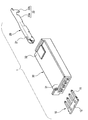
- FIG. 1 is an exploded perspective view of a joint connector as a connector according to an embodiment of the present invention.
- FIG. 2 is a perspective view showing the connector housing of the joint connector shown in FIG. 1 upside down.
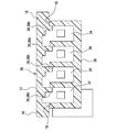
- 3 is a cross-sectional view taken along arrow III-III in FIG.
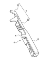
- FIG. 4 is a perspective view showing a configuration of terminals used in the joint connector shown in FIG.
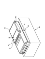
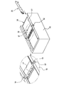
- FIG. 5 is a perspective view showing a state where the joint connector shown in FIG. 1 is about to be attached to the assembly jig.
- 6 is a perspective view showing a state in which all the lances are bent by mounting the joint connector shown in FIG. 1 on an assembly jig, and an enlarged view of a main part thereof.
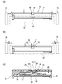
- FIG. 7 (a) to 7 (c) are explanatory views of the assembly procedure of the joint connector shown in FIG. 1, and FIG. 7 (a) is a side view showing a state in which the joint connector is started to be mounted on the assembly jig.
- FIG. 7B is a side view showing a state in which all the lances are bent by attaching the joint connector to the assembly jig
- FIG. 7C is an assembly jig after all terminals are inserted. It is a sectional side view which shows the state which returned the lance from the bending and was made to engage with a terminal by removing a connector housing from.
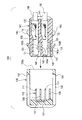
- FIG. 8 is a longitudinal sectional view of a conventional joint connector in an exploded state.
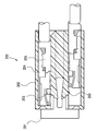
- FIG. 9 is a side sectional view showing a configuration of a conventional connector.
- FIG. 1 is an exploded perspective view of the joint connector of the embodiment
- FIG. 2 is a perspective view showing the connector housing of the joint connector upside down
- FIG. 3 is a cross-sectional view taken along arrow III-III in FIG. 2
- FIG. 5 is a perspective view illustrating a state in which the joint connector is to be mounted on the assembly jig
- FIG. 6 is a view in which the joint connector is mounted on the assembly jig.
- FIG. 7A to FIG. 7C are explanatory views of the assembly procedure of the joint connector
- FIG. FIG. 7B is a side view showing a state in which the joint connector starts to be attached to the assembly jig
- FIG. 7B shows a state in which all the lances are bent by attaching the joint connector to the assembly jig.
- Side view, FIG. 7 (c) by removing the connector housing from the assembly jig after the insertion of all the terminal is a side sectional view showing a state in which to return the engaged and the terminal from the deflection lance.
- the joint connector 1 includes a joint terminal 10, a female terminal fitting 20, and a resin connector housing 30.
- the joint terminal 10 is a press-molded product of a metal plate, and includes a plurality of tab pieces 11 for fitting and connecting the female terminal fitting 20 and a connecting portion 12 that electrically connects these tab pieces 11.
- the female terminal fitting 20 is a press-molded product of a metal plate and extends from a rectangular tube-shaped box portion 21 into which the tab piece 11 is fitted and a rear end of the box portion 21 as shown in FIGS. 1 and 4.
- An electric wire caulking portion 22 for taking out and crimping an electric wire and an insertion guide protrusion 24 are provided.
- the electric wire crimping portion 22 includes a conductor crimping piece 22a for crimping the conductor of the electric wire and a covering crimping piece 22b for fixing the electric wire by crimping the electric wire covering portion.
- the insertion guide protrusion 24 is a tongue-like piece extending in the insertion direction into the female terminal receiving hole 34 of the connector housing 30 described later at a position near the rear end of the box portion 21.
- the insertion guide protrusion 24 is formed in a tongue shape by extending a part of the side wall of the box portion 21 and bending it. In this embodiment, when the female terminal fitting 20 is inserted to the proper position, the lance 36 is engaged with the insertion guide protrusion 24 to prevent the female terminal fitting 20 from coming off. Has been.
- the connector housing 30 is a resin injection-molded product, and includes a housing main body portion 38, a housing one end portion 31, a housing other end portion 32 that is an end opposite to the housing one end portion 31, and a terminal locking plate 39. And.
- the housing one end 31 accommodates and holds the joint terminal 10 with the tab piece 11 facing the housing other end 32 side.
- a plurality of female terminal receiving holes 34 are arranged in a line in a plane along the left-right direction orthogonal to the front-rear direction.
- the plurality of female terminal receiving holes 34 are holes that bring the female terminal fitting 20 and the tab piece 11 into a fitted state by inserting the female terminal fitting 20 to a specified position.
- the specified position is a position at which the tab piece 11 and the box portion 21 obtain a contact length necessary and sufficient for electrical connection.
- the housing body is provided with a flexible lance 36 that prevents the female terminal fitting 20 inserted into the terminal receiving hole 34 from the rear side from coming off.
- the lance 36 includes a terminal locking projection 36b.
- the terminal locking protrusion 36b protrudes toward the female terminal accommodating hole 34, and as shown in FIG. 7C, the terminal locking protrusion 36b engages with the insertion guide protrusion 24 inserted at the specified position, thereby The terminal fitting 20 is secured.
- the terminal locking plate 39 is a wall-like body whose base end side 40 is coupled to the housing main body portion 38 and whose free end side is free to be bent, and an opening 38 a formed on the vertical plate surface of the housing main body portion 38.
- the housing body 38 is formed of synthetic resin so as to be embedded.
- the terminal locking plate 39 is configured such that all the lances 36 provided for each of the terminal receiving holes 34 are integrally connected by a connecting member 17 extending in the left-right direction. At both ends, there is provided an operating portion 18 that bends all the lances 36 by operating the connecting member 17.
- the left and right operation portions 18 protrude outward from the left and right ends of the housing main body 38 and are accommodated in a recess 19 formed on the side wall of the housing main body 38 when the lance 36 is not bent.
- the assembly jig 50 is used when the female terminal fitting 20 is inserted into each terminal accommodating chamber 34 of the connector housing 30, and has a rectangular top view open for insertion of the connector housing 30.
- the connector housing 30 is inserted into the insertion recess 51 with the back side facing up at the peripheral edge (upper edge) of the insertion recess 51, the left and right ends of the connecting member 17 are operated.
- An engaging portion 52 is provided that interferes with the portion 18 to operate the connecting member 17 to bend all the lances 36.
- the engaging part 52 is provided as a concave part into which the operation part 18 is fitted from above.
- the holding device 70 shown in FIGS. 7A and 7B is used.
- the holding device 70 is used when the connector housing 30 is inserted into the assembly jig 50, and is used for holding and fixing the connector housing 30.
- the joint terminal 10 made of a bus bar is attached to the front portion of the connector housing 30.
- the connector housing 30 is inserted into the insertion recess 51 of the assembly jig 50 with the back side facing up.
- the operating portions 18 provided at both ends of the connecting member 17 of the terminal locking plate 39 hit the engaging portion 52 at the peripheral edge of the insertion recess 51 of the assembling jig 50 and are pushed by the engaging portion 52.
- the terminal locking plate 39 is lifted upward as indicated by an arrow Y in FIG.
- all the lances 36 provided for each terminal accommodating chamber 34 are provided integrally with the terminal locking plate 39, all the lances 36 avoid the retaining of the female terminal fitting 20.
- all of the female terminal fittings 20 can be inserted into the terminal accommodating holes 34 of the connector housing 30 by bending all at once in the direction of retreating from the female terminal accommodating holes 34.
- the connector housing 30 is lifted from the assembly jig 50 and taken out.
- the interference between the operation portion 18 of the terminal locking plate 39 and the engaging portion 52 of the assembly jig 50 is eliminated, so that the terminal locking plate 39 returns to the initial position. All the lances 36 are restored from the bending, and engage with the female terminal fittings 20 to prevent the female terminal fittings 20 from coming off.
- the female terminal fitting 20 can be inserted with the lance 36 bent in advance, the insertion force of the female terminal fitting 20 can be reduced. Further, since the lance 36 itself is integrally connected, there is no need for a holder for bending all the lances 36 at the same time as in the conventional example, and the number of parts can be reduced. Moreover, since all the lances 36 are integrally connected, the rigidity of the lances 36 can be increased, and thereby the holding force of the female terminal fitting 20 can be increased.
- the lances 36 corresponding to the female terminal fittings 20 in the mid-insertion state do not return to the fixed positions, so that all the lances 36 And since it will be in the state where the connection member 14 does not return to an initial position, it turns out easily that there exists the female terminal metal fitting 20 of a half insertion state.
- the female terminal fitting 20 is inserted into each terminal accommodating chamber 34 in a state where the joint terminal 10 is accommodated in the connector housing 30 in advance. Since the joint terminal 10 can be fitted, the female terminal fitting 20 can be temporarily locked even when the lance 36 is in a bent state (disengaged state).
- the present invention is applied to the joint connector that interconnects the female terminal fittings 20 by the joint member 40
- the present invention can also be applied to other connectors.
- the present invention it is possible to reduce the insertion force of the female terminal fitting, reduce the number of parts, facilitate the assembly work of the female terminal fitting, and detect the half insertion of the female terminal fitting. Can be facilitated and the holding force of the female terminal fitting can be increased.
Landscapes
- Engineering & Computer Science (AREA)
- Manufacturing & Machinery (AREA)
- Connector Housings Or Holding Contact Members (AREA)
- Manufacturing Of Electrical Connectors (AREA)
- Details Of Connecting Devices For Male And Female Coupling (AREA)
Abstract
Priority Applications (3)
| Application Number | Priority Date | Filing Date | Title |
|---|---|---|---|
| DE112012000903T DE112012000903T5 (de) | 2011-02-18 | 2012-02-10 | Verbinder und Montagevorrichtung für Verbinder |
| CN201280009534XA CN103380549A (zh) | 2011-02-18 | 2012-02-10 | 连接器和用于连接器的组装夹具 |
| US13/982,976 US20130309913A1 (en) | 2011-02-18 | 2012-02-10 | Connector and Assembly Jig for Connector |
Applications Claiming Priority (2)
| Application Number | Priority Date | Filing Date | Title |
|---|---|---|---|
| JP2011033711A JP2012174430A (ja) | 2011-02-18 | 2011-02-18 | コネクタ及び該コネクタの組立用治具 |
| JP2011-033711 | 2011-02-18 |
Publications (1)
| Publication Number | Publication Date |
|---|---|
| WO2012111572A1 true WO2012111572A1 (fr) | 2012-08-23 |
Family
ID=46672496
Family Applications (1)
| Application Number | Title | Priority Date | Filing Date |
|---|---|---|---|
| PCT/JP2012/053171 Ceased WO2012111572A1 (fr) | 2011-02-18 | 2012-02-10 | Cosse, et fixation pour assemblage de cette cosse |
Country Status (6)
| Country | Link |
|---|---|
| US (1) | US20130309913A1 (fr) |
| JP (1) | JP2012174430A (fr) |
| CN (1) | CN103380549A (fr) |
| DE (1) | DE112012000903T5 (fr) |
| TW (1) | TWI469701B (fr) |
| WO (1) | WO2012111572A1 (fr) |
Cited By (1)
| Publication number | Priority date | Publication date | Assignee | Title |
|---|---|---|---|---|
| WO2015014714A1 (fr) * | 2013-07-29 | 2015-02-05 | Tyco Electronics Amp Gmbh | Fiche de type débrochable ayant un bloc de chambre et moyens d'assujettissement par contact |
Families Citing this family (4)
| Publication number | Priority date | Publication date | Assignee | Title |
|---|---|---|---|---|
| JP6112399B2 (ja) * | 2013-03-14 | 2017-04-12 | 住友電装株式会社 | コネクタ及びコネクタの製造方法 |
| JP6206392B2 (ja) * | 2014-12-25 | 2017-10-04 | 株式会社オートネットワーク技術研究所 | ジョイントコネクタ |
| JP6914529B2 (ja) * | 2017-12-22 | 2021-08-04 | 日本圧着端子製造株式会社 | 電気コネクタ |
| JP7271471B2 (ja) * | 2020-05-19 | 2023-05-11 | 矢崎総業株式会社 | コネクタ |
Citations (6)
| Publication number | Priority date | Publication date | Assignee | Title |
|---|---|---|---|---|
| JPH10214650A (ja) * | 1997-01-30 | 1998-08-11 | Yazaki Corp | コネクタ |
| JP2001006788A (ja) * | 1999-06-03 | 2001-01-12 | Whitaker Corp:The | 電気コネクタ及び電気コネクタ用ケース |
| JP2002184506A (ja) * | 2000-12-15 | 2002-06-28 | Sumitomo Wiring Syst Ltd | コネクタ |
| JP2005050794A (ja) * | 2003-07-17 | 2005-02-24 | Auto Network Gijutsu Kenkyusho:Kk | ワイヤハーネス用ジョイントコネクタ |
| JP2007012451A (ja) * | 2005-06-30 | 2007-01-18 | Sumitomo Wiring Syst Ltd | ジョイントコネクタ |
| JP2007012352A (ja) * | 2005-06-29 | 2007-01-18 | Sumitomo Wiring Syst Ltd | コネクタ |
Family Cites Families (7)
| Publication number | Priority date | Publication date | Assignee | Title |
|---|---|---|---|---|
| JPH0688135U (ja) * | 1993-05-24 | 1994-12-22 | 住友電装株式会社 | 分岐接続箱 |
| JPH08250185A (ja) | 1995-01-13 | 1996-09-27 | Sumitomo Wiring Syst Ltd | ジョイントコネクタ及びジョイントコネクタ用キャップ |
| US5769650A (en) * | 1995-06-19 | 1998-06-23 | Sumitomo Wiring Systems, Ltd. | Connector and cover therefor |
| JPH0935800A (ja) | 1995-07-18 | 1997-02-07 | Sumitomo Wiring Syst Ltd | コネクタ |
| US7351085B2 (en) * | 2003-07-17 | 2008-04-01 | Autonetworks Technologies, Ltd. | Joint member and joint connector for wire harness |
| TWM309248U (en) * | 2006-06-05 | 2007-04-01 | Hon Hai Prec Ind Co Ltd | Tool for carrying a central processing unit |
| JP2011033711A (ja) | 2009-07-30 | 2011-02-17 | Nikon Corp | レンズ鏡筒及びカメラ |
-
2011
- 2011-02-18 JP JP2011033711A patent/JP2012174430A/ja not_active Abandoned
-
2012
- 2012-02-10 DE DE112012000903T patent/DE112012000903T5/de not_active Withdrawn
- 2012-02-10 US US13/982,976 patent/US20130309913A1/en not_active Abandoned
- 2012-02-10 CN CN201280009534XA patent/CN103380549A/zh active Pending
- 2012-02-10 WO PCT/JP2012/053171 patent/WO2012111572A1/fr not_active Ceased
- 2012-02-17 TW TW101105203A patent/TWI469701B/zh not_active IP Right Cessation
Patent Citations (6)
| Publication number | Priority date | Publication date | Assignee | Title |
|---|---|---|---|---|
| JPH10214650A (ja) * | 1997-01-30 | 1998-08-11 | Yazaki Corp | コネクタ |
| JP2001006788A (ja) * | 1999-06-03 | 2001-01-12 | Whitaker Corp:The | 電気コネクタ及び電気コネクタ用ケース |
| JP2002184506A (ja) * | 2000-12-15 | 2002-06-28 | Sumitomo Wiring Syst Ltd | コネクタ |
| JP2005050794A (ja) * | 2003-07-17 | 2005-02-24 | Auto Network Gijutsu Kenkyusho:Kk | ワイヤハーネス用ジョイントコネクタ |
| JP2007012352A (ja) * | 2005-06-29 | 2007-01-18 | Sumitomo Wiring Syst Ltd | コネクタ |
| JP2007012451A (ja) * | 2005-06-30 | 2007-01-18 | Sumitomo Wiring Syst Ltd | ジョイントコネクタ |
Cited By (1)
| Publication number | Priority date | Publication date | Assignee | Title |
|---|---|---|---|---|
| WO2015014714A1 (fr) * | 2013-07-29 | 2015-02-05 | Tyco Electronics Amp Gmbh | Fiche de type débrochable ayant un bloc de chambre et moyens d'assujettissement par contact |
Also Published As
| Publication number | Publication date |
|---|---|
| DE112012000903T5 (de) | 2013-11-14 |
| TWI469701B (zh) | 2015-01-11 |
| CN103380549A (zh) | 2013-10-30 |
| TW201236522A (en) | 2012-09-01 |
| US20130309913A1 (en) | 2013-11-21 |
| JP2012174430A (ja) | 2012-09-10 |
Similar Documents
| Publication | Publication Date | Title |
|---|---|---|
| EP1936749B1 (fr) | Organe de contact, connecteur et procédé de fabrication | |
| CN104508913B (zh) | 连接器 | |
| JP6527911B2 (ja) | コネクタ | |
| JP4963702B2 (ja) | 端子位置保証装置を有するコネクタ組立体 | |
| CN105390872A (zh) | 连接器组件 | |
| JP6138428B2 (ja) | コネクタ | |
| US20130330956A1 (en) | Joint Connector | |
| CN102265464B (zh) | 电连接器 | |
| CN104662742A (zh) | 连接器 | |
| CN101779337B (zh) | 电连接器 | |
| WO2016208368A1 (fr) | Connecteur de raccordement | |
| WO2012111572A1 (fr) | Cosse, et fixation pour assemblage de cette cosse | |
| JP5947485B2 (ja) | 中継コネクタ | |
| CN110581370B (zh) | 端子和连接器 | |
| CN111384644A (zh) | 接头连接器 | |
| JP2018014300A (ja) | コネクタ | |
| WO2012111528A1 (fr) | Dispositif de cosse de raccordement | |
| JP5107004B2 (ja) | 合体コネクタ | |
| JP6641320B2 (ja) | コネクタ | |
| WO2012111529A1 (fr) | Cosse de raccordement, et dispositif d'assemblage de cosse | |
| JP4871628B2 (ja) | コネクタ | |
| JP6004539B2 (ja) | コネクタ | |
| JP7243551B2 (ja) | コネクタ | |
| JP6684448B2 (ja) | 電気接続箱 | |
| CN117321863A (zh) | 连接器 |
Legal Events
| Date | Code | Title | Description |
|---|---|---|---|
| 121 | Ep: the epo has been informed by wipo that ep was designated in this application |
Ref document number: 12747777 Country of ref document: EP Kind code of ref document: A1 |
|
| WWE | Wipo information: entry into national phase |
Ref document number: 13982976 Country of ref document: US |
|
| WWE | Wipo information: entry into national phase |
Ref document number: 112012000903 Country of ref document: DE Ref document number: 1120120009037 Country of ref document: DE |
|
| 122 | Ep: pct application non-entry in european phase |
Ref document number: 12747777 Country of ref document: EP Kind code of ref document: A1 |