WO2012114732A1 - Procédé de formation d'un court-circuit dans un faisceau de câbles - Google Patents
Procédé de formation d'un court-circuit dans un faisceau de câbles Download PDFInfo
- Publication number
- WO2012114732A1 WO2012114732A1 PCT/JP2012/001186 JP2012001186W WO2012114732A1 WO 2012114732 A1 WO2012114732 A1 WO 2012114732A1 JP 2012001186 W JP2012001186 W JP 2012001186W WO 2012114732 A1 WO2012114732 A1 WO 2012114732A1
- Authority
- WO
- WIPO (PCT)
- Prior art keywords
- sheet body
- joint connector
- electric wire
- sheet
- short circuit
- Prior art date
- Legal status (The legal status is an assumption and is not a legal conclusion. Google has not performed a legal analysis and makes no representation as to the accuracy of the status listed.)
- Ceased
Links
Images






Classifications
-
- H—ELECTRICITY
- H01—ELECTRIC ELEMENTS
- H01R—ELECTRICALLY-CONDUCTIVE CONNECTIONS; STRUCTURAL ASSOCIATIONS OF A PLURALITY OF MUTUALLY-INSULATED ELECTRICAL CONNECTING ELEMENTS; COUPLING DEVICES; CURRENT COLLECTORS
- H01R31/00—Coupling parts supported only by co-operation with counterpart
- H01R31/08—Short-circuiting members for bridging contacts in a counterpart
-
- H—ELECTRICITY
- H01—ELECTRIC ELEMENTS
- H01R—ELECTRICALLY-CONDUCTIVE CONNECTIONS; STRUCTURAL ASSOCIATIONS OF A PLURALITY OF MUTUALLY-INSULATED ELECTRICAL CONNECTING ELEMENTS; COUPLING DEVICES; CURRENT COLLECTORS
- H01R4/00—Electrically-conductive connections between two or more conductive members in direct contact, i.e. touching one another; Means for effecting or maintaining such contact; Electrically-conductive connections having two or more spaced connecting locations for conductors and using contact members penetrating insulation
- H01R4/70—Insulation of connections
Definitions
- the present invention relates to a method for forming a short circuit by connecting specific wires among a plurality of wires included in the wire harness, and a wire harness including the short circuit in a wire harness of an automobile or the like. It relates to a method for manufacturing.
- the joint connector includes, for example, a plurality of connector terminals that are respectively attached to terminals of specific wires among a plurality of wires bundled together in the wire harness, a connector housing that holds these connector terminals, and the connector housing And a short-circuit conductor that short-circuits the connector terminals by fitting with the connector terminals.
- Patent Document 1 discloses that the joint connector is inserted into a bag-like connector cover made of an elastic material, and the connector cover is opened. It is described that the side end portion is brought into close contact with each electric wire connected to the joint connector using its elastic restoring force.
- the opening end of the connector cover is brought into close contact with the electric wire only by its elastic restoring force, the opening end of the connector cover is securely attached to all the plural electric wires.
- a considerable elastic restoring force is required, and it is not easy to obtain such an elastic restoring force.
- the natural opening diameter of the connector cover (the diameter when not elastically deformed) must be set to be considerably smaller than the maximum outer diameter of the joint connector. Inserting the joint connector into the cover is very troublesome. That is, the operator must forcibly expand the opening of the connector cover with a very large force using a special jig or the like. Also, automation of such operations is extremely difficult.
- the method provided by the present invention includes a short-circuiting step of short-circuiting these electric wires by connecting terminals of a plurality of electric wires included in the wire harness to a common joint connector; A waterproof body manufacturing process for forming a waterproof body that seals and waterproofs the joint connector by closely contacting an end portion of an electric wire connected to the joint connector while covering the joint connector in the periphery.
- the waterproof body manufacturing process includes a first sheet body, an end of each joint connector and each electric wire connected thereto, and a second sheet body around the joint connector and the electric wire.
- An overlapping process in which both side portions in the width direction of the first sheet body and the peripheral portion of the second sheet body are directly brought into contact with each other, and air from the side of the first sheet body in the overlapping state
- the joint connector between the two sheet bodies is brought into close contact with the peripheral portion of the second sheet body and the peripheral portion of the first sheet body by sucking Sealing step for sealing.
- the air suction may be performed from the stage of the superimposing step. That is, the timing at which the air suction is started does not matter before or after completion of the superposition process.
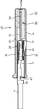
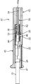
- FIG. 1 shows a wire harness 100 according to this embodiment and a joint connector JC used to form a short circuit of the wire harness 100.
- the joint connector JC is waterproofed by being sealed inside a waterproof body 50 including a first sheet body 52A and a second sheet body 52B as shown in FIG.
- the wire harness 100 according to this embodiment is manufactured by the following process.
- a plurality of electric wires 10 are bundled to form the main wire 12, and a plurality of the electric wires 10 (four in this embodiment) Is drawn out from the trunk line 12 as the branch wire group 14.
- the state where the electric wire 10 was bundled is hold
- Each electric wire 10 is a so-called covered electric wire, and the electric wire 10 has a conductor and an insulating coating that covers the conductor.
- the electric wire side terminals 20 in order to connect the electric wires 10 included in the branch electric wire group 14 to the common joint connector JC, the electric wire side terminals 20 as shown in FIGS. It is installed.
- the electric wire side terminal 20 has a female electrical contact portion 22 and an electric wire crimping portion 24 at the front and rear.
- the electrical contact portion 22 has a hollow rectangular tube-shaped main body and a contact spring piece 26 provided so as to be able to bend in the main body. From the bottom wall of the electrical contact portion 22, a locked piece 28 for locking to the joint connector JC protrudes outward.
- each electric wire 10 included in the branch electric wire group 14 is previously subjected to a treatment for removing the insulating coating and exposing the conductor, and the electric wire crimping portion 24 is connected to the end of the conductor and the vicinity thereof.
- the electric wire crimping portion 24 is connected to the end of the conductor and the vicinity thereof.
- the joint connector JC includes a single short-circuit conductor 30 and an insulating housing 40 for holding the short-circuit conductor 30.
- the short-circuiting conductor 30 is made of a conductive material, and is short-circuited between the electric wire side terminals 20 by being commonly connected to the electric wire side terminals 20.
- the insulating housing 40 is integrally formed of an insulating material such as synthetic resin, and can be held in a state in which the shorting conductor 30 is stored, specifically, the thickness direction of the shorting conductor 30. It has a flat shape.
- the short-circuit conductor 30 is composed of a short-circuit metal plate formed by punching a single metal plate into an appropriate shape, and a plurality of fitting portions 32 and short-circuit portions 34 are integrated.
- Each fitting portion 32 is a male (tab) fitting portion that can be fitted into the female electrical contact portion 22 of each electric wire side terminal 20, and these fitting portions 32 are parallel to the width direction thereof. It is arranged in the direction, that is, the direction orthogonal to the thickness direction of the metal plate for short circuit.
- the short-circuit portion 34 extends in the arrangement direction of the fitting portions 32, and the short ends 34 are connected to the base ends of the fitting portions 32.
- the insulating housing 40 has a pair of side walls that connect the flat top wall 41 and the bottom wall 42 that are parallel to each other, and both ends of the walls 41 and 42 in the width direction (that is, the left end portions and the right end portions). 44 integrally. These walls 41, 42, 44 constitute the outer wall of the insulating housing 40.
- the rear end portion (right end portion in FIGS. 3 to 6) of the outer wall constitutes a conductor holding portion 43.
- the short-circuit portion 34 is held by the conductor holding portion 43 by press-fitting the short-circuit portion 34 of the short-circuiting conductor 30 into the conductor holding portion 43 from the opening 43 a.
- the conductor holding portion 43 has a shape for holding the short-circuit portion 34 of the short-circuit conductor 30. Specifically, it has an outer shape that is slightly larger than the short-circuit portion 34 and extends in the arrangement direction of the fitting portions 32 of the short-circuit conductor 30, and the short-circuit portion 34 is inserted from the rear (left side in FIG. 8). A possible short-circuit metal plate insertion opening 43a is enclosed.
- the short-circuit portion 34 is press-fitted into the conductor holding portion 43 from the insertion port 43a with the fitting portions 32 facing forward. More specifically, protrusions 34 a as shown in FIG. 6 are formed at both ends in the width direction of the short-circuit part 34, and these conductors 34 a dig into the inner side surface of the conductor holding part 43.
- the short-circuit part 34 is fixed to.
- a plurality of (three in the figure) partition walls 45 parallel to the side walls 44 are arranged in the connector width direction at a portion on the front side of the conductor holding portion 43.
- Each partition wall 45 defines a terminal accommodating chamber 47 between another partition wall 45 or a side wall 44 adjacent thereto.
- These terminal accommodating chambers 47 are formed corresponding to the respective fitting portions 32 and receive the electric wire side terminals 20 so as to allow the electric wire side terminals 20 to be fitted into the fitting portions 32. It has a shape, specifically a shape that opens forward and allows the wire-side terminal 20 to be inserted through the opening.
- each fitting portion 32 of the short-circuiting conductor 30 protrudes from the rear, and the electric contact portion 22 of the electric wire side terminal 20 inserted into the terminal accommodating chamber 47 is the fitting portion.
- the electric wire side terminal 20 and the short-circuiting conductor 30 are electrically connected to each other by being engaged with the terminal 32.
- the bottom wall 42 is formed with a lance 46 that is a terminal locking portion at a position corresponding to each terminal accommodating chamber 47.
- each lance 46 has a slit 42a formed in the bottom wall 42, that is, a pair of parallel linear portions extending in the front-rear direction of the connector and the ends of these linear portions are connected to each other in the connector width.
- a claw-like locking portion 46a is formed at the free end.
- the engaging portion 46a is flexibly displaced as shown in FIG. 3 by coming into contact with the inserted electric wire side terminal 20, and allows the electric wire side terminal 20 to pass. By returning, the locked piece 28 of the electric wire side terminal 20 is restrained from the rear.
- the lance 46 has a locking position (position shown in FIG. 4) where the locking portion 46 a locks the electric wire side terminal 20 at a position where the electric wire side terminal 20 is engaged with the fitting portion 32. And a retraction position (position shown in FIG. 3) that retreats to the outside with the elastic deformation of the lance 46 from this locking position, which is the same as the outer surface of the other part of the bottom wall 42 at the locking position. It is located on the surface and protrudes outward from the outer surface of the other part of the bottom wall 42 at the retracted position.
- the wire-side terminal 20 at the end of the wire 10 included in the branch wire group 14 is inserted into the terminal accommodating chamber 47 and is directly fitted into the fitting portion 32 of the short-circuiting conductor 30.
- the short circuit between the electric wire side terminals 20 using the shorting conductor 30 as a connection medium is achieved. That is, the short circuit about the some electric wire 10 with which the said electric wire side terminal 20 was each mounted
- a waterproof body 50 as shown in FIG. 2 is formed around the joint connector JC and an end portion 10a of the electric wire 10 connected thereto (the electric wires 10 included in the branch wire group 14). By sealing the joint connector JC, the short circuit is waterproofed.
- the waterproof body 50 can be efficiently manufactured by the following process, for example.
- This process includes the first sheet body 52A having a dimension sufficiently larger than the planar shape of the joint connector JC, the joint connector JC, and the electric wires 10 connected thereto, as shown in FIG.
- the thickness of the joint connector JC includes the end portion 10a and the second sheet body 52B having a dimension sufficiently larger than the planar shape of the joint connector JC (having a shape larger than the first sheet body 52A in this embodiment).
- the peripheral portion 52a of the first sheet body 52A and the peripheral portion 52b of the second sheet body 52B can directly contact each other around the joint connector JC and the electric wire 10. It is done to become.
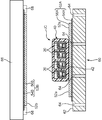
- a vacuum forming die 60 as shown in FIG. 7 is used for forming the waterproof body 50.
- the vacuum forming die 60 has a flat upper surface, which forms a forming surface 62.
- a plurality of suction ports 64 are opened on the molding surface 62, and these suction ports 64 are connected to a vacuum pump (not shown) through an air passage formed in the vacuum molding die 60. Air above the suction port 64 is sucked.
- the first sheet body 52B is laid on the molding surface 62 of the vacuum forming mold 60.
- the first sheet body 52A is constituted by a sheet made of, for example, a synthetic resin.
- a number of ventilation holes are provided in the peripheral portion 52a of the first sheet body 52A (the portion protruding outward from the joint connector JC) in order to promote close contact with the second sheet body 52B by air suction described later. May be.
- the diameter of the vent hole is preferably about 3 mm, for example.
- the joint connector JC and the end portion 10a of the electric wire 10 connected to the joint connector JC are placed on the first sheet body 52A in a relative positional relationship such that the first sheet body 52A protrudes outside the joint connector JC.
- the second sheet body 52B is also composed of a synthetic resin, for example, a sheet made of a synthetic resin made of the same material as the first sheet body 52A. Then, the second sheet body 52B covers the joint connector JC and the electric wire 10 connected thereto so that the peripheral portion 52b of the second sheet body 52B is in direct contact with the peripheral portion 52a of the first sheet body 52A. It is done.
- the material of the two sheet bodies 52A and 52B is not particularly limited, but at least the second sheet body 52B is more preferably a thermoplastic resin such as polyvinyl chloride, polyethylene, or polyester. Since the second sheet body 52B made of such a thermoplastic resin is softened by being heated, the thickness of the second sheet body 52B is set to be relatively large in order to ensure the strength of the second sheet body 52B. Even if the flexibility of the second sheet body 52B at room temperature is low, the second sheet body 52B is sufficiently softened to the shape of the joint connector JC and the end portion 10a of the electric wire 10 connected thereto due to the softening. The peripheral portion 52a of the body 52A and the surface of the electric wire 10 can be satisfactorily contacted.
- a thermoplastic resin such as polyvinyl chloride, polyethylene, or polyester. Since the second sheet body 52B made of such a thermoplastic resin is softened by being heated, the thickness of the second sheet body 52B is set to be relatively large in order to ensure the strength of the second sheet
- a heater 66 as shown in FIG. 7 is disposed above the vacuum forming die 60, and the second sheet body 52B is held by the holding portion 68 on the lower surface of the heater 66 and softened.
- the second sheet body 52B is preferably cut off from the heater 66 and placed on the joint connector JC and the end portion 10a of the electric wire 10 connected thereto.
- the suction of air from the suction port 64 may be performed only in the next sealing step, but preferably it is performed from the stage of the superimposing step.
- the suction of the air in the overlapping step holds the first sheet body 52A on the molding surface 62, and further, the second sheet body 52B on the first sheet body 52A and the joint connector JC. Contributes to attraction.
- the distance between the electric wires 10 becomes narrower as the distance from the joint connector JC increases.
- the both sheets can be used regardless of the distance between the electric wires 10.
- the bodies 52 ⁇ / b> A and 52 ⁇ / b> B can be satisfactorily adhered to the surface of each electric wire 10 by the vacuum forming mold 60.
- the contact state between the peripheral portions 52a and 52b of the both sheet bodies 52A and 52B is more reliably maintained by bonding the peripheral portions 52a and 52b to each other.
- the adhesive provided on the sheet body layer for example, the above-described synthetic resin sheet
- the back surface the surface facing the other sheet body. What has an agent layer should just be prepared.
- the adhesive layer strengthens the contact state by adhering the peripheral portions 52a and 52b of the two sheet bodies 52A and 52B.
- a flexible material such as a butyl rubber-based pressure-sensitive adhesive or a thermosetting liquid agent such as an epoxy resin is suitable.
- both the first sheet body 52A and the second sheet body 52B include an adhesive layer. That is, the first sheet body 52A includes a sheet main body layer 54A and an adhesive layer 56A provided on the back surface thereof, and the second sheet body 52B includes a sheet main body layer 54B and an adhesive layer 56B provided on the back surface thereof. have. According to such a combination of sheet bodies 52A and 52B, not only the peripheral portions 52a and 52b are in close contact with each other, but also the peripheral portions 52a and 52b (on the rear end side) as shown in FIG. The close contact with the surface of the portion 10a is also firmly held by adhesion by the adhesive layers 56A and 56B.
- the method described above does not require the troublesome work of inserting the joint connector into the waterproof body while forcibly expanding the opening of the bag-shaped waterproof body with a dedicated jig as in the prior art.
- the operator can surely form the short circuit and waterproof it by a process with very little burden.
- This method is particularly suitable for the case where at least a part of the electric wire side terminal 20 is composed of different metal materials for the electric wire side terminal 10 and the electric wire to which the electric wire side terminal 10 is attached.
- the electric wire side terminal 20 is made of an alloy and is made of copper or a copper alloy, a significant advantage is exhibited. That is, the wire-side terminal 20 composed of different metal materials and the conductor to which the wire-side terminal 20 is attached are likely to corrode when moisture enters the joint portion, so that the short circuit including the wire-side terminal 20 is surely provided. Waterproofing greatly contributes to improvement of connection reliability and extension of life.
- the specific shape and structure of the joint connector used is not particularly limited.
- the connector terminals may be arranged over a plurality of upper and lower stages, or the electric wire side terminal 20 and the short-circuiting conductor 30 may be held in separate connector housings, and these connector housings may be fitted together. .
- the joint connector JC as shown in each figure has a flat shape with a small dimension in the thickness direction
- the joint connector JC and the electric wire 10 connected to the joint connector JC and both sheet bodies 52A and 52B are arranged in the thickness direction.
- the close contact between the peripheral portions 52a and 52b of both the sheet bodies 52A and 52B and the close contact between the peripheral portions 52a and 52b and the surface of the electric wire 10 are more easily and reliably performed.
- the lance 46 as the terminal locking portion is formed on the outer wall (the bottom wall 42 in the figure) as described above, the dimension in the thickness direction is further reduced, and the lance 46 is in its retracted position. In this case, the lance 46 is moved outside by the first sheet body 52A or the second sheet body 52B (the first sheet body 52A in FIG. 8) at the locking position.
- the outer wall (the bottom wall 42 in this embodiment) of the joint connector JC is restrained from the outside by using the first sheet body 52A or the second sheet body 52B that seals the joint connector JC. Therefore, it is possible to prevent the lance 46 from being displaced from the locking position to the retracted position, so that the joint connector JC is not provided with a special structure for double-locking the electric wire side terminal 20, that is, the joint. It is possible to more reliably hold the wire-side terminal 20 by the lance 46 while keeping the shape of the connector JC thin.
- a method capable of easily forming a waterproof short circuit in a wire harness including a plurality of electric wires bundled together includes a short-circuiting step of short-circuiting these electric wires by connecting ends of a plurality of electric wires included in the wire harness to a common joint connector, and the joint around the joint connector.
- the waterproof body manufacturing process includes a first sheet body, an end of each joint connector and each electric wire connected thereto, and a second sheet body around the joint connector and the electric wire.
- the electric wire side terminals are respectively attached to the ends of the specific electric wires
- the joint connector is made of a single metal plate and has a plurality of fitting portions arranged in a direction perpendicular to the thickness direction. Then, each fitting portion is fitted to each of the electric wire side terminals, and the shorting metal plate for short-circuiting the electric wires in the fitted state, and a flat outer shape in the thickness direction of the shorting metal plate
- a plurality of terminal accommodating chambers for holding the wire-side terminals so as to hold the short-circuiting metal plate and allow the wire-side terminals to be fitted into the fitting portions of the short-circuiting metal plate. It is preferred to use an insulating housing that surrounds the housing.
- the joint connector and the end portion of the electric wire connected thereto have a flat shape as a whole (the thickness direction that is perpendicular to the arrangement direction of the electric wires is small), by overlapping both sheet bodies in the thickness direction, It is possible to more reliably and easily join the two sheet bodies.
- the joint connector has an outer wall facing the terminal accommodating chamber, and a terminal locking portion for locking the electric wire side terminal is formed on the outer wall, and the terminal locking portion locks the electric wire side terminal.
- the terminal locking portion is elastically displaceable between the locking position and the retracted position retracted outward from the locking position and projecting outward from the outer wall. It is preferable that the peripheral portions of both sheet bodies are joined together so as to be restrained from the outside by the one sheet body or the second sheet body.
- the terminal engagement portion formed on the outer wall of the joint connector is constrained to the engagement position by using the first sheet body or the second sheet body that is in close contact with the joint connector. It is possible to prevent the stop portion from being displaced from the locking position to the retracted position, and to more reliably hold the state in which the terminal locking portion locks the electric wire side terminal.
- the method according to the present invention can be performed more efficiently by using a vacuum forming die having a forming surface in which a plurality of suction ports for sucking air are opened.
- the superimposing step lays the first sheet body on the molding surface, and the peripheral portion of the first sheet body is the joint connector and The joint connector and the end of the electric wire connected to the first connector are placed on the first sheet so as to protrude outside the end of the electric wire connected thereto, and the second sheet is attached to the second sheet.
- the second sheet body includes a layer made of a thermoplastic resin, and the layer is softened by heating, and the joint connector and the end of the electric wire connected thereto and the first sheet body It is more preferable to cover the peripheral portion of the sheet body.
- the second sheet body is heated and softened so that the second sheet body is connected to the joint connector and the wires connected thereto. While conforming to the shape of the end, the end of the electric wire and the peripheral portion of the first sheet body can be satisfactorily adhered. Therefore, both the setting of the thickness of the second sheet body for ensuring the strength of the second sheet body and the sealing and waterproofing of the joint connector by the close contact between the first and second sheet bodies can be achieved.
- a sheet body layer and a back surface of the sheet body layer It is more preferable that what has an adhesive layer provided in is used, and the peripheral parts of both sheet bodies are adhere
- This method is for at least some of the electric wire side terminals connected to the joint connector, when the electric wire side terminal and the conductor of the electric wire on which the electric wire side terminal is mounted are made of different metal materials, It is particularly effective. If moisture enters the joint portion between the electric wire side terminal composed of different metal materials and the conductor of the electric wire contacting this, there is a risk of accelerating corrosion of the electric wire side terminal or the conductor. It is extremely significant to securely waterproof a short circuit including such a combination of a different metal wire side terminal and a conductor by the method according to the present invention.
- the present invention also provides a method for efficiently producing a wire harness having a short circuit.
- the specific electric wires are short-circuited by applying the step of bundling a plurality of electric wires and the method for forming the short circuit for the terminals of the specific electric wires among the electric wires. Forming a short circuit and producing a waterproof body for sealing the short circuit.
Landscapes
- Manufacturing Of Electric Cables (AREA)
- Connector Housings Or Holding Contact Members (AREA)
Abstract
La présente invention se rapporte à un procédé avec lequel il est facile de former un court-circuit résistant à l'eau dans un faisceau de câbles qui contient une pluralité de câbles électriques regroupés en un faisceau. Ce procédé contient : une étape consistant à créer un court-circuit par raccordement des extrémités d'une pluralité de câbles électriques spécifiques (10) avec un connecteur de raccordement (JC) partagé ; et une étape consistant à former un corps résistant à l'eau (50) et à disposer de façon étanche le connecteur de raccordement (JC) à l'intérieur de ce corps résistant à l'eau (50), ce qui permet de rendre étanche à l'eau le connecteur de raccordement (JC). L'étape consistant à former un corps résistant à l'eau (50) comprend : une étape consistant à stratifier un premier corps de type feuille (52A), le connecteur de raccordement (JC) et la partie d'extrémité (10a) de chaque câble électrique (10) raccordé à ce dernier, avec un second corps de type feuille (52B) ; et une étape au cours de laquelle, par aspiration de l'air provenant du côté premier corps de type feuille (52A) dans cet état stratifié, la partie périphérique (52b) du second corps de type feuille (52B) et la partie périphérique (52a) du premier corps de type feuille (52A) sont collés l'une à l'autre, et les corps de type feuille (52A et 52B) sont collées aux surfaces des parties d'extrémité (10a) des câbles électriques (10).
Applications Claiming Priority (2)
| Application Number | Priority Date | Filing Date | Title |
|---|---|---|---|
| JP2011038020A JP5732901B2 (ja) | 2011-02-24 | 2011-02-24 | ワイヤハーネスにおける短絡回路の形成方法 |
| JP2011-038020 | 2011-02-24 |
Publications (1)
| Publication Number | Publication Date |
|---|---|
| WO2012114732A1 true WO2012114732A1 (fr) | 2012-08-30 |
Family
ID=46720524
Family Applications (1)
| Application Number | Title | Priority Date | Filing Date |
|---|---|---|---|
| PCT/JP2012/001186 Ceased WO2012114732A1 (fr) | 2011-02-24 | 2012-02-22 | Procédé de formation d'un court-circuit dans un faisceau de câbles |
Country Status (2)
| Country | Link |
|---|---|
| JP (1) | JP5732901B2 (fr) |
| WO (1) | WO2012114732A1 (fr) |
Cited By (1)
| Publication number | Priority date | Publication date | Assignee | Title |
|---|---|---|---|---|
| WO2022209626A1 (fr) * | 2021-03-29 | 2022-10-06 | 住友電装株式会社 | Élément de câblage |
Families Citing this family (2)
| Publication number | Priority date | Publication date | Assignee | Title |
|---|---|---|---|---|
| PT106994A (pt) | 2013-06-09 | 2014-12-09 | Active Space Technologies Actividades Aeroespaciais Lda | Método e sistema de monitorização de envelhecimento de cablagens eléctricas |
| JP2015069748A (ja) * | 2013-09-27 | 2015-04-13 | 住友電装株式会社 | コネクタ付ワイヤハーネスの防水構造 |
Citations (7)
| Publication number | Priority date | Publication date | Assignee | Title |
|---|---|---|---|---|
| JPS63157163U (fr) * | 1987-04-01 | 1988-10-14 | ||
| JPH02212125A (ja) * | 1988-10-20 | 1990-08-23 | Yazaki Corp | 導体接続部の製造方法 |
| JPH09102332A (ja) * | 1995-07-31 | 1997-04-15 | Yazaki Corp | フラット回路体のジョイント部及びその製造方法 |
| JPH11111065A (ja) * | 1997-09-30 | 1999-04-23 | Yazaki Corp | 回路体及びその製造方法 |
| JP2009207299A (ja) * | 2008-02-28 | 2009-09-10 | Sumitomo Wiring Syst Ltd | 車両用ワイヤハーネスのスプライス収容構造 |
| JP2010177037A (ja) * | 2009-01-29 | 2010-08-12 | Autonetworks Technologies Ltd | アース接続用配線材、これに用いられるジョイントコネクタ、及びアース接続用配線材が組み込まれたワイヤハーネス |
| JP2011165376A (ja) * | 2010-02-05 | 2011-08-25 | Autonetworks Technologies Ltd | ワイヤハーネスの短絡部の製造方法、及びワイヤハーネスの短絡部 |
-
2011
- 2011-02-24 JP JP2011038020A patent/JP5732901B2/ja not_active Expired - Fee Related
-
2012
- 2012-02-22 WO PCT/JP2012/001186 patent/WO2012114732A1/fr not_active Ceased
Patent Citations (7)
| Publication number | Priority date | Publication date | Assignee | Title |
|---|---|---|---|---|
| JPS63157163U (fr) * | 1987-04-01 | 1988-10-14 | ||
| JPH02212125A (ja) * | 1988-10-20 | 1990-08-23 | Yazaki Corp | 導体接続部の製造方法 |
| JPH09102332A (ja) * | 1995-07-31 | 1997-04-15 | Yazaki Corp | フラット回路体のジョイント部及びその製造方法 |
| JPH11111065A (ja) * | 1997-09-30 | 1999-04-23 | Yazaki Corp | 回路体及びその製造方法 |
| JP2009207299A (ja) * | 2008-02-28 | 2009-09-10 | Sumitomo Wiring Syst Ltd | 車両用ワイヤハーネスのスプライス収容構造 |
| JP2010177037A (ja) * | 2009-01-29 | 2010-08-12 | Autonetworks Technologies Ltd | アース接続用配線材、これに用いられるジョイントコネクタ、及びアース接続用配線材が組み込まれたワイヤハーネス |
| JP2011165376A (ja) * | 2010-02-05 | 2011-08-25 | Autonetworks Technologies Ltd | ワイヤハーネスの短絡部の製造方法、及びワイヤハーネスの短絡部 |
Cited By (6)
| Publication number | Priority date | Publication date | Assignee | Title |
|---|---|---|---|---|
| WO2022209626A1 (fr) * | 2021-03-29 | 2022-10-06 | 住友電装株式会社 | Élément de câblage |
| JP2022152925A (ja) * | 2021-03-29 | 2022-10-12 | 住友電装株式会社 | 配線部材 |
| JP2024113003A (ja) * | 2021-03-29 | 2024-08-21 | 住友電装株式会社 | 配線部材 |
| JP7625930B2 (ja) | 2021-03-29 | 2025-02-04 | 住友電装株式会社 | 配線部材 |
| JP7761087B2 (ja) | 2021-03-29 | 2025-10-28 | 住友電装株式会社 | 配線部材 |
| US12463373B2 (en) | 2021-03-29 | 2025-11-04 | Sumitomo Wiring Systems, Ltd. | Wiring member |
Also Published As
| Publication number | Publication date |
|---|---|
| JP2012174632A (ja) | 2012-09-10 |
| JP5732901B2 (ja) | 2015-06-10 |
Similar Documents
| Publication | Publication Date | Title |
|---|---|---|
| JP5672158B2 (ja) | コネクタの製造方法 | |
| JP5792011B2 (ja) | フラットケーブル防水コネクタ構造、及びその接続方法 | |
| JP5448756B2 (ja) | シールドフラットケーブル及びその接続構造 | |
| US9378867B2 (en) | Terminal-fitted wire, terminal-fitted wire manufacturing method and corrosion resistant member | |
| CN105453342B (zh) | 压接端子相对于电线的连接结构 | |
| WO2013039253A1 (fr) | Borne de connecteur | |
| JP2015069748A (ja) | コネクタ付ワイヤハーネスの防水構造 | |
| CN105048117A (zh) | 端子连接结构和端子连接方法 | |
| JP4391268B2 (ja) | 防水圧接コネクタとその製造方法 | |
| JP2002170627A (ja) | 防水コネクタ及びその製造方法 | |
| CN106340750A (zh) | 带连接器的电线、和带连接器的电线的制造方法 | |
| JP5732901B2 (ja) | ワイヤハーネスにおける短絡回路の形成方法 | |
| JP2012009335A (ja) | 端子金具の製造方法 | |
| JP5609685B2 (ja) | ワイヤハーネスに設けられるシールド体の製造方法 | |
| US9219327B2 (en) | Waterproof flat cable connector and method for manufacturing same | |
| WO2021006052A1 (fr) | Module de câblage, module de stockage de puissance, barre omnibus et procédé de fabrication de module de stockage de puissance | |
| JP2013134963A (ja) | 防水コネクタの製造方法 | |
| JP2013134965A (ja) | 防水コネクタの製造方法及び防水コネクタ | |
| JP2013134964A (ja) | 防水コネクタの製造方法及び防水コネクタ | |
| JP2018092734A (ja) | 端子付き電線、端子、ワイヤハーネス | |
| JP3110998B2 (ja) | フラット回路体のジョイント部及びその製造方法 | |
| WO2009084350A1 (fr) | Prise de masse | |
| JP5800204B2 (ja) | 銅電線とアルミ電線の接続構造 | |
| JP5510738B2 (ja) | コネクタ | |
| JP2002325325A (ja) | 配線材及びその製造方法 |
Legal Events
| Date | Code | Title | Description |
|---|---|---|---|
| 121 | Ep: the epo has been informed by wipo that ep was designated in this application |
Ref document number: 12750189 Country of ref document: EP Kind code of ref document: A1 |
|
| NENP | Non-entry into the national phase |
Ref country code: DE |
|
| 122 | Ep: pct application non-entry in european phase |
Ref document number: 12750189 Country of ref document: EP Kind code of ref document: A1 |