WO2012117677A1 - 加熱調理器 - Google Patents
加熱調理器 Download PDFInfo
- Publication number
- WO2012117677A1 WO2012117677A1 PCT/JP2012/000931 JP2012000931W WO2012117677A1 WO 2012117677 A1 WO2012117677 A1 WO 2012117677A1 JP 2012000931 W JP2012000931 W JP 2012000931W WO 2012117677 A1 WO2012117677 A1 WO 2012117677A1
- Authority
- WO
- WIPO (PCT)
- Prior art keywords
- heating
- heating chamber
- door
- main body
- cooking device
- Prior art date
- Legal status (The legal status is an assumption and is not a legal conclusion. Google has not performed a legal analysis and makes no representation as to the accuracy of the status listed.)
- Ceased
Links
Images




Classifications
-
- H—ELECTRICITY
- H05—ELECTRIC TECHNIQUES NOT OTHERWISE PROVIDED FOR
- H05B—ELECTRIC HEATING; ELECTRIC LIGHT SOURCES NOT OTHERWISE PROVIDED FOR; CIRCUIT ARRANGEMENTS FOR ELECTRIC LIGHT SOURCES, IN GENERAL
- H05B6/00—Heating by electric, magnetic or electromagnetic fields
- H05B6/64—Heating using microwaves
- H05B6/6402—Aspects relating to the microwave cavity
-
- F—MECHANICAL ENGINEERING; LIGHTING; HEATING; WEAPONS; BLASTING
- F24—HEATING; RANGES; VENTILATING
- F24C—DOMESTIC STOVES OR RANGES ; DETAILS OF DOMESTIC STOVES OR RANGES, OF GENERAL APPLICATION
- F24C7/00—Stoves or ranges heated by electric energy
- F24C7/02—Stoves or ranges heated by electric energy using microwaves
-
- H—ELECTRICITY
- H05—ELECTRIC TECHNIQUES NOT OTHERWISE PROVIDED FOR
- H05B—ELECTRIC HEATING; ELECTRIC LIGHT SOURCES NOT OTHERWISE PROVIDED FOR; CIRCUIT ARRANGEMENTS FOR ELECTRIC LIGHT SOURCES, IN GENERAL
- H05B6/00—Heating by electric, magnetic or electromagnetic fields
- H05B6/64—Heating using microwaves
Definitions
- the present invention relates to a cooking device, and more particularly to a cooking device having at least high-frequency heating means as means for heating an object to be heated.
- the height dimension of the heating chamber with respect to the width or depth dimension of the heating chamber is set to 1/2 or more.
- a vertically openable or laterally openable door that can be opened and closed is provided so as to cover the front opening of the heating chamber (see, for example, Patent Document 1 and Patent Document 2).
- the extra space in the height direction is large.
- microwaves that are not absorbed by the object to be heated are repeatedly reflected and attenuated on the wall surface of the heating chamber, so that the energy loss increases.
- the technical problem of the present invention is to reduce the number of reflections of the microwaves on the wall surface of the heating chamber by the range heating, thereby reducing the energy loss and shortening the heating time.
- the cooking device has the following configuration. That is, a main body, a heating chamber provided in the main body and having a front opening, high-frequency heating means provided in the main body for heating an object to be heated, and a front opening in the heating chamber.
- a heating cooker provided with an openable / closable door
- the height dimension of the heating chamber with respect to the width or depth dimension of the heating chamber is 1 ⁇ 2 or less.
- the cooking device of the present invention since the height dimension of the heating chamber with respect to the width or depth dimension of the heating chamber is 1 ⁇ 2 or less, the surplus space in the height direction in the heating chamber is reduced, and Microwaves that are not absorbed by the heated object can be irradiated to the object to be heated with a small number of reflections. For this reason, an energy loss can be made small and a heating time can be shortened.
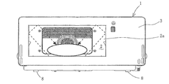
- FIG. 1 is a front view showing a cooking device according to an embodiment of the present invention with a door removed.
- FIG. 2 is a front view which shows the state at the time of the range heating of the heating cooker which concerns on embodiment of this invention in the state which removed the door.
- FIG. 3 is a front view which shows the state at the time of oven heating of the heating cooker which concerns on embodiment of this invention in the state which removed the door.
- FIG. 4 is a side view showing the relationship between the door and the support leg of the cooking device according to the embodiment of the present invention with the door opened.
- the heating cooker according to the embodiment of the present invention has a range heating function and an oven heating function.
- the inside of the main body 1 formed in a rectangular parallelepiped shape as shown in FIG. 1 is defined by a heating chamber 2 and an electric chamber 3, and a front opening 2 a through which an object to be heated 4 is taken in and out is formed in the heating chamber 2.
- the front opening 2a is opened and closed by a door 5 (FIG. 4) having a window.
- the door 5 is composed of a vertically opened door 5 whose lower side is pivotally supported by the main body 1, and a handle 6 is provided at the center of the upper side.
- a magnetron (not shown) that is a high-frequency heating means is arranged.
- the heating chamber 2 is provided with a feeding port (not shown) for irradiating the heating chamber with microwaves emitted from the magnetron on the bottom surface. (Not shown).
- the heating chamber 2 is formed in a box shape having a front opening by a bottom wall 2b, a side wall 2c, a rear wall 2d, a top wall 2e, and a front wall 2f.
- the top diaphragm 2g has an upper constricted portion 2g recessed upward
- the upper heater 7a which is a heater heating means such as a flat heater, is heated in the upper constricted portion 2g. It is disposed in close contact with the surface on the chamber 2 side.
- a lower restricting portion 2h is provided in the bottom wall 2b as shown in FIG.
- a lower heater 7b composed of, for example, a sheathed heater as heater heating means is provided in the lower restricting portion 2h. It is arranged in close contact with the surface on the heating chamber 2 side.
- guides 12 are provided on both side walls 2c of the heating chamber 2 to hold the square plate 11 on which the object to be heated 4 is placed at an intermediate position in the height direction, and at the four corners on the lower surface of the main body 1, Support legs 8 are provided.
- the heating chamber 2 is set so that the height dimension B of the heating chamber 2 with respect to the width dimension A (or depth dimension) of the heating chamber 2 is 1/2 or less as shown in FIG. Has been.
- the width or depth dimension A of the heating chamber 2 is set to 300 mm, which is the width or depth that can accommodate the platter, because most of the platters used in Japan are less than 300 mm as a result of the investigation. It is.
- the height dimension B of the heating chamber is set to 140 mm, which is the height that can accommodate most of the mugs in Japan. By the way, as a result of the survey, about half of the mugs in Japan were 90 mm or less in height, and 96% were 140 mm or less in height.
- the vertical door 5 is set such that the distance I 1 from the fulcrum (hinge axis) to the free end is shorter than the distance L in the front-rear direction between the support legs 8.
- F1 in FIG. 4 is a force (load) due to the weight of the main body 1 and the door 5 applied to the support leg 8 located in the front
- F2 is a force of the main body 1 and the door 5 applied to the support leg 8 located in the rear.
- F3 is the force (load) due to the dead weight of the door 5
- F4 is the force (load) that tries to rotate the main body 1 counterclockwise around F1 (try to tilt forward).
- F2 is larger (F4 ⁇ F2) than the force F4 trying to tilt forward, indicating that the force is stable.
- the cooking device according to the embodiment of the present invention is set so that the height dimension B of the heating chamber 2 with respect to the width dimension A (or depth dimension) of the heating chamber 2 is 1/2 or less, Since the surplus space in the height direction in the heating chamber is small, the object to be heated can be irradiated with a small number of reflections with microwaves that are not absorbed by the object to be heated 4 as shown in FIG.
- the height dimension of the heating chamber 2 is compressed to reflect on the top wall 2e in the heating chamber.
- the ratio of the irradiated microwaves to the object to be heated 4 is increased, the energy loss is smaller, and the heating time can be shortened.
- FIG. 7 is a graph showing the effect of the range heating efficiency by the heating cooker according to the embodiment of the present invention in comparison with the comparative example, where the vertical axis indicates the output (W) and the horizontal axis indicates the heating chamber capacity (L).
- 10L corresponds to the cooking device of the present invention.
- the object to be heated is heated with a heater or the like.
- the wall surface of the heating chamber also enters the radiation area of the heater. For this reason, not only a to-be-heated material but a heating chamber wall surface is heated, and a thermal energy loss becomes large.
- the height dimension B of the heating chamber 2 with respect to the width dimension A (or depth dimension) of the heating chamber 2 is set to be 1/2 or less, and the heating chamber Since the surplus space in the height direction is small, the wall surface of the heating chamber does not enter the radiation area of the upper and lower heaters 7a and 7b outside the heating chamber 2 as shown in FIG. Since most of the radiant heat can be irradiated toward the object 4 to be heated, the heat energy loss transmitted to the wall surface of the heating chamber is small, and the heating time can be greatly shortened.
- the heating time is greatly shortened and the heat energy loss transmitted to the wall surface of the heating chamber is reduced, so that the temperature in the heating chamber does not rise even after heating the heater, and there is no risk of burns even when using a range immediately. .
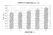
- FIG. 6 is a graph showing the effect of the heater heating efficiency by the heating cooker according to the embodiment of the present invention in comparison with a comparative example, where the vertical axis represents input (KJ) and the horizontal axis represents heating chamber capacity (L).
- the capacity of the heating chamber is reduced by reducing the height of the heating chamber from that of the conventional heating chamber capacity of 30 L, and the estimated efficiency improvement when the heating chamber temperature reaches 200 ° C. is estimated.
- 13L corresponds to the cooking device of the present invention.
- the heater heating efficiency is improved by 74.6% compared to the 30L one. Obtained.
- FIG. 5 is a side view which shows the relationship between the door (vertical opening door) and supporting leg of the heating cooker of a comparative example in the state which opened the door.
- the height dimension of the heating chamber with respect to the width or depth dimension of the heating chamber is set to 1/2 or more as shown in FIG.
- F5 in FIG. 5 is a force (load) due to the weight of the main body 1 and the door 5a applied to the support leg 8 positioned at the front
- F6 is the force of the main body 1 and the door 5a applied to the support leg 8 positioned at the rear.
- F7 is a force (load) due to the weight of the door 5a
- F7 is a force (load) due to the weight of the door 5a
- F8 is a force (load) that attempts to rotate the main body 1 counterclockwise around F5 (tries to the front side).
- the height of the naturally longitudinal opening doors 5a in accordance with the height of the heating chamber i.e., the distance I 2 to the free end from the hinge axis of the longitudinal opening door 5a is also increased. Therefore, the force F8 to topple frontward large (F8> F6) becomes than F6, centroid position M 2 g of body 1 present between the front and rear support legs 8, 8, to fully open the vertical opening doors 5a It will be closer to the front.
- the height dimension B of the heating chamber 2 with respect to the width dimension A (or depth dimension) of the heating chamber 2 is set to be 1 ⁇ 2 or less.
- the door height that is, the distance I 1 from the hinge shaft to the free end of the vertically opening door 5 is also reduced in accordance with the height of the heating chamber.
- the distance I 1 from the hinge axis to the free end of the vertical door 5 is set to be shorter than the distance L between the front and rear support legs 8, 8.
- the center of gravity M 1g of the main body 1 which exist between the 8 does not change much even when allowed to fully open the vertical opening door 5.
- the rotation center position (front) when the main body 1 falls forward here.
- the distance between the front and rear support legs 8, 8 in the front-rear direction is larger than the distance from the free end when the vertical door 5 is fully opened to the support leg 8 positioned forward, and the magnetron that is a heavy object is It arrange
Landscapes
- Engineering & Computer Science (AREA)
- Physics & Mathematics (AREA)
- Electromagnetism (AREA)
- Chemical & Material Sciences (AREA)
- Combustion & Propulsion (AREA)
- Mechanical Engineering (AREA)
- General Engineering & Computer Science (AREA)
- Electric Ovens (AREA)
- Constitution Of High-Frequency Heating (AREA)
Abstract
Description
図1は本発明の実施形態に係る加熱調理器を扉を外した状態で示す正面図である。図2は本発明の実施形態に係る加熱調理器のレンジ加熱時の状態を扉を外した状態で示す正面図である。図3は本発明の実施形態に係る加熱調理器のオーブン加熱時の状態を扉を外した状態で示す正面図である。図4は本発明の実施形態に係る加熱調理器の扉と支持脚との関係を扉を開けた状態で示す側面図である。
2 加熱室
2a 加熱室の前面開口
2b 底壁
2c 側壁
2d 後壁
2e 頂壁
2f 前壁
2g 上部絞り部
2h 下部絞り部
3 電気室
4 被加熱物
5,5a 縦開き扉(扉)
6 ハンドル
7a 上ヒーター(ヒーター加熱手段)
7b 下ヒーター(ヒーター加熱手段)
8 支持脚
11 角皿
12 ガイド
A 加熱室の幅寸法
B 加熱室の高さ寸法
I1,I2 縦開き扉の支点から自由端までの距離
M1g,M2g 本体の重心位置
Claims (5)
- 本体と、
前記本体の内部に設けられ、前面が開口する加熱室と、
前記本体の内部に設けられ、前記加熱室内に収納された被加熱物を加熱する高周波加熱手段と、
前記加熱室の前面開口を覆う開閉自在な扉と、を備えた加熱調理器において、
前記加熱室の幅または奥行きの寸法に対する該加熱室の高さ寸法を1/2以下としたことを特徴とする加熱調理器。 - 前記加熱室の底面に、前記高周波加熱手段から発せられたマイクロ波を前記加熱室内に照射するための給電口を配置したことを特徴とする請求項1記載の加熱調理器。
- 前記加熱室の室外に、前記加熱室内に収納された被加熱物を加熱するヒーター加熱手段を更に設けたことを特徴とする請求項1又は請求項2記載の加熱調理器。
- 前記本体は、その下面の四隅部に支持脚を有し、
前記扉は、その下辺部が前記本体に軸支された縦開き扉で構成され、かつ該縦開き扉の支点から自由端までの距離が、前記支持脚間の前後方向の距離よりも短くなるようにしたことを特徴とする請求項1乃至請求項3のいずれか一項に記載の加熱調理器。 - 前記本体は、その下面の四隅部に支持脚を有し、
前記扉は、その下辺部が前記本体に軸支された縦開き扉で構成されており、
前記支持脚間の前後方向の距離は、前記縦開き扉の全開時の自由端から前方に位置する前記支持脚までの距離より大きく、かつ前記高周波加熱手段の配置位置は、前記本体の奥行き方向の中間位置よりも後方に位置することを特徴とする請求項1乃至請求項3のいずれか一項に記載の加熱調理器。
Priority Applications (3)
| Application Number | Priority Date | Filing Date | Title |
|---|---|---|---|
| JP2013502171A JPWO2012117677A1 (ja) | 2011-03-02 | 2012-02-13 | 加熱調理器 |
| KR1020137022599A KR20130112066A (ko) | 2011-03-02 | 2012-02-13 | 가열 조리기 |
| CN2012800110227A CN103403455A (zh) | 2011-03-02 | 2012-02-13 | 加热烹调器 |
Applications Claiming Priority (2)
| Application Number | Priority Date | Filing Date | Title |
|---|---|---|---|
| JP2011045075 | 2011-03-02 | ||
| JP2011-045075 | 2011-03-02 |
Publications (1)
| Publication Number | Publication Date |
|---|---|
| WO2012117677A1 true WO2012117677A1 (ja) | 2012-09-07 |
Family
ID=46757623
Family Applications (1)
| Application Number | Title | Priority Date | Filing Date |
|---|---|---|---|
| PCT/JP2012/000931 Ceased WO2012117677A1 (ja) | 2011-03-02 | 2012-02-13 | 加熱調理器 |
Country Status (4)
| Country | Link |
|---|---|
| JP (1) | JPWO2012117677A1 (ja) |
| KR (1) | KR20130112066A (ja) |
| CN (1) | CN103403455A (ja) |
| WO (1) | WO2012117677A1 (ja) |
Citations (8)
| Publication number | Priority date | Publication date | Assignee | Title |
|---|---|---|---|---|
| JPH0574561A (ja) * | 1991-09-17 | 1993-03-26 | Toshiba Corp | 高周波加熱装置 |
| JPH09101036A (ja) * | 1995-10-03 | 1997-04-15 | Toshiba Corp | 電子レンジ |
| JP2000121062A (ja) * | 1998-10-19 | 2000-04-28 | Matsushita Electric Ind Co Ltd | 高周波加熱装置 |
| JP2005100673A (ja) * | 2003-09-22 | 2005-04-14 | Matsushita Electric Ind Co Ltd | 高周波加熱装置 |
| JP2006329495A (ja) * | 2005-05-25 | 2006-12-07 | Matsushita Electric Ind Co Ltd | 高周波加熱装置 |
| JP2008258091A (ja) * | 2007-04-09 | 2008-10-23 | Matsushita Electric Ind Co Ltd | マイクロ波加熱装置 |
| JP2008309481A (ja) * | 2008-09-29 | 2008-12-25 | Panasonic Corp | 加熱調理器 |
| JP2011102661A (ja) * | 2009-11-10 | 2011-05-26 | Mitsubishi Electric Corp | 加熱調理器 |
-
2012
- 2012-02-13 WO PCT/JP2012/000931 patent/WO2012117677A1/ja not_active Ceased
- 2012-02-13 JP JP2013502171A patent/JPWO2012117677A1/ja active Pending
- 2012-02-13 CN CN2012800110227A patent/CN103403455A/zh active Pending
- 2012-02-13 KR KR1020137022599A patent/KR20130112066A/ko not_active Ceased
Patent Citations (8)
| Publication number | Priority date | Publication date | Assignee | Title |
|---|---|---|---|---|
| JPH0574561A (ja) * | 1991-09-17 | 1993-03-26 | Toshiba Corp | 高周波加熱装置 |
| JPH09101036A (ja) * | 1995-10-03 | 1997-04-15 | Toshiba Corp | 電子レンジ |
| JP2000121062A (ja) * | 1998-10-19 | 2000-04-28 | Matsushita Electric Ind Co Ltd | 高周波加熱装置 |
| JP2005100673A (ja) * | 2003-09-22 | 2005-04-14 | Matsushita Electric Ind Co Ltd | 高周波加熱装置 |
| JP2006329495A (ja) * | 2005-05-25 | 2006-12-07 | Matsushita Electric Ind Co Ltd | 高周波加熱装置 |
| JP2008258091A (ja) * | 2007-04-09 | 2008-10-23 | Matsushita Electric Ind Co Ltd | マイクロ波加熱装置 |
| JP2008309481A (ja) * | 2008-09-29 | 2008-12-25 | Panasonic Corp | 加熱調理器 |
| JP2011102661A (ja) * | 2009-11-10 | 2011-05-26 | Mitsubishi Electric Corp | 加熱調理器 |
Also Published As
| Publication number | Publication date |
|---|---|
| KR20130112066A (ko) | 2013-10-11 |
| JPWO2012117677A1 (ja) | 2014-07-07 |
| CN103403455A (zh) | 2013-11-20 |
Similar Documents
| Publication | Publication Date | Title |
|---|---|---|
| US7161125B2 (en) | Cooking appliance | |
| US20120285437A1 (en) | Door of electric oven | |
| JP2016007428A (ja) | グリル装置 | |
| JP2004265616A (ja) | マイクロ波加熱装置 | |
| WO2012117677A1 (ja) | 加熱調理器 | |
| US10663173B2 (en) | Electric cooking appliance | |
| US20100212512A1 (en) | Cooking apparatus | |
| KR20160126625A (ko) | 전기밥솥 | |
| JP2011075125A (ja) | マイクロ波加熱調理器 | |
| CN104879802B (zh) | 微波炉 | |
| US9980323B2 (en) | High-frequency heating cooker | |
| JP7233169B2 (ja) | 加熱調理器 | |
| JP2014235838A (ja) | 加熱調理器 | |
| JP2016110729A (ja) | 加熱調理器 | |
| KR20220123973A (ko) | 조리기기 | |
| JP2022116464A (ja) | 加熱調理器 | |
| JP2016050737A (ja) | 加熱調理器 | |
| JP2008067997A (ja) | 高周波加熱装置 | |
| US20250008617A1 (en) | Cooking appliance | |
| CN215937095U (zh) | 一种烤箱的加热结构 | |
| CN204739637U (zh) | 微波炉 | |
| JP7313312B2 (ja) | 加熱調理器 | |
| JP4575236B2 (ja) | 加熱調理器 | |
| KR101623853B1 (ko) | 조리기기 | |
| JP2005164091A (ja) | 加熱調理器 |
Legal Events
| Date | Code | Title | Description |
|---|---|---|---|
| 121 | Ep: the epo has been informed by wipo that ep was designated in this application |
Ref document number: 12752217 Country of ref document: EP Kind code of ref document: A1 |
|
| ENP | Entry into the national phase |
Ref document number: 2013502171 Country of ref document: JP Kind code of ref document: A |
|
| ENP | Entry into the national phase |
Ref document number: 20137022599 Country of ref document: KR Kind code of ref document: A |
|
| NENP | Non-entry into the national phase |
Ref country code: DE |
|
| 122 | Ep: pct application non-entry in european phase |
Ref document number: 12752217 Country of ref document: EP Kind code of ref document: A1 |