WO2012120598A1 - Système de commande d'alimentation en carburant destiné à un moteur à combustion interne polycarburant - Google Patents
Système de commande d'alimentation en carburant destiné à un moteur à combustion interne polycarburant Download PDFInfo
- Publication number
- WO2012120598A1 WO2012120598A1 PCT/JP2011/055096 JP2011055096W WO2012120598A1 WO 2012120598 A1 WO2012120598 A1 WO 2012120598A1 JP 2011055096 W JP2011055096 W JP 2011055096W WO 2012120598 A1 WO2012120598 A1 WO 2012120598A1
- Authority
- WO
- WIPO (PCT)
- Prior art keywords
- fuel
- heat generation
- generation rate
- internal combustion
- combustion engine
- Prior art date
- Legal status (The legal status is an assumption and is not a legal conclusion. Google has not performed a legal analysis and makes no representation as to the accuracy of the status listed.)
- Ceased
Links
Images



Classifications
-
- F—MECHANICAL ENGINEERING; LIGHTING; HEATING; WEAPONS; BLASTING
- F02—COMBUSTION ENGINES; HOT-GAS OR COMBUSTION-PRODUCT ENGINE PLANTS
- F02D—CONTROLLING COMBUSTION ENGINES
- F02D19/00—Controlling engines characterised by their use of non-liquid fuels, pluralities of fuels, or non-fuel substances added to the combustible mixtures
- F02D19/06—Controlling engines characterised by their use of non-liquid fuels, pluralities of fuels, or non-fuel substances added to the combustible mixtures peculiar to engines working with pluralities of fuels, e.g. alternatively with light and heavy fuel oil, other than engines indifferent to the fuel consumed
- F02D19/0602—Control of components of the fuel supply system
- F02D19/0605—Control of components of the fuel supply system to adjust the fuel pressure or temperature
-
- F—MECHANICAL ENGINEERING; LIGHTING; HEATING; WEAPONS; BLASTING
- F02—COMBUSTION ENGINES; HOT-GAS OR COMBUSTION-PRODUCT ENGINE PLANTS
- F02D—CONTROLLING COMBUSTION ENGINES
- F02D19/00—Controlling engines characterised by their use of non-liquid fuels, pluralities of fuels, or non-fuel substances added to the combustible mixtures
- F02D19/06—Controlling engines characterised by their use of non-liquid fuels, pluralities of fuels, or non-fuel substances added to the combustible mixtures peculiar to engines working with pluralities of fuels, e.g. alternatively with light and heavy fuel oil, other than engines indifferent to the fuel consumed
- F02D19/0602—Control of components of the fuel supply system
- F02D19/0607—Control of components of the fuel supply system to adjust the fuel mass or volume flow
- F02D19/061—Control of components of the fuel supply system to adjust the fuel mass or volume flow by controlling fuel injectors
-
- F—MECHANICAL ENGINEERING; LIGHTING; HEATING; WEAPONS; BLASTING
- F02—COMBUSTION ENGINES; HOT-GAS OR COMBUSTION-PRODUCT ENGINE PLANTS
- F02D—CONTROLLING COMBUSTION ENGINES
- F02D19/00—Controlling engines characterised by their use of non-liquid fuels, pluralities of fuels, or non-fuel substances added to the combustible mixtures
- F02D19/06—Controlling engines characterised by their use of non-liquid fuels, pluralities of fuels, or non-fuel substances added to the combustible mixtures peculiar to engines working with pluralities of fuels, e.g. alternatively with light and heavy fuel oil, other than engines indifferent to the fuel consumed
- F02D19/0663—Details on the fuel supply system, e.g. tanks, valves, pipes, pumps, rails, injectors or mixers
- F02D19/0686—Injectors
- F02D19/0692—Arrangement of multiple injectors per combustion chamber
-
- F—MECHANICAL ENGINEERING; LIGHTING; HEATING; WEAPONS; BLASTING
- F02—COMBUSTION ENGINES; HOT-GAS OR COMBUSTION-PRODUCT ENGINE PLANTS
- F02D—CONTROLLING COMBUSTION ENGINES
- F02D19/00—Controlling engines characterised by their use of non-liquid fuels, pluralities of fuels, or non-fuel substances added to the combustible mixtures
- F02D19/06—Controlling engines characterised by their use of non-liquid fuels, pluralities of fuels, or non-fuel substances added to the combustible mixtures peculiar to engines working with pluralities of fuels, e.g. alternatively with light and heavy fuel oil, other than engines indifferent to the fuel consumed
- F02D19/08—Controlling engines characterised by their use of non-liquid fuels, pluralities of fuels, or non-fuel substances added to the combustible mixtures peculiar to engines working with pluralities of fuels, e.g. alternatively with light and heavy fuel oil, other than engines indifferent to the fuel consumed simultaneously using pluralities of fuels
- F02D19/081—Adjusting the fuel composition or mixing ratio; Transitioning from one fuel to the other
-
- F—MECHANICAL ENGINEERING; LIGHTING; HEATING; WEAPONS; BLASTING
- F02—COMBUSTION ENGINES; HOT-GAS OR COMBUSTION-PRODUCT ENGINE PLANTS
- F02D—CONTROLLING COMBUSTION ENGINES
- F02D35/00—Controlling engines, dependent on conditions exterior or interior to engines, not otherwise provided for
- F02D35/02—Controlling engines, dependent on conditions exterior or interior to engines, not otherwise provided for on interior conditions
- F02D35/023—Controlling engines, dependent on conditions exterior or interior to engines, not otherwise provided for on interior conditions by determining the cylinder pressure
-
- F—MECHANICAL ENGINEERING; LIGHTING; HEATING; WEAPONS; BLASTING
- F02—COMBUSTION ENGINES; HOT-GAS OR COMBUSTION-PRODUCT ENGINE PLANTS
- F02D—CONTROLLING COMBUSTION ENGINES
- F02D35/00—Controlling engines, dependent on conditions exterior or interior to engines, not otherwise provided for
- F02D35/02—Controlling engines, dependent on conditions exterior or interior to engines, not otherwise provided for on interior conditions
- F02D35/025—Controlling engines, dependent on conditions exterior or interior to engines, not otherwise provided for on interior conditions by determining temperatures inside the cylinder, e.g. combustion temperatures
- F02D35/026—Controlling engines, dependent on conditions exterior or interior to engines, not otherwise provided for on interior conditions by determining temperatures inside the cylinder, e.g. combustion temperatures using an estimation
-
- F—MECHANICAL ENGINEERING; LIGHTING; HEATING; WEAPONS; BLASTING
- F02—COMBUSTION ENGINES; HOT-GAS OR COMBUSTION-PRODUCT ENGINE PLANTS
- F02D—CONTROLLING COMBUSTION ENGINES
- F02D41/00—Electrical control of supply of combustible mixture or its constituents
- F02D41/0025—Controlling engines characterised by use of non-liquid fuels, pluralities of fuels, or non-fuel substances added to the combustible mixtures
-
- F—MECHANICAL ENGINEERING; LIGHTING; HEATING; WEAPONS; BLASTING
- F02—COMBUSTION ENGINES; HOT-GAS OR COMBUSTION-PRODUCT ENGINE PLANTS
- F02D—CONTROLLING COMBUSTION ENGINES
- F02D19/00—Controlling engines characterised by their use of non-liquid fuels, pluralities of fuels, or non-fuel substances added to the combustible mixtures
- F02D19/06—Controlling engines characterised by their use of non-liquid fuels, pluralities of fuels, or non-fuel substances added to the combustible mixtures peculiar to engines working with pluralities of fuels, e.g. alternatively with light and heavy fuel oil, other than engines indifferent to the fuel consumed
- F02D19/0639—Controlling engines characterised by their use of non-liquid fuels, pluralities of fuels, or non-fuel substances added to the combustible mixtures peculiar to engines working with pluralities of fuels, e.g. alternatively with light and heavy fuel oil, other than engines indifferent to the fuel consumed characterised by the type of fuels
- F02D19/0642—Controlling engines characterised by their use of non-liquid fuels, pluralities of fuels, or non-fuel substances added to the combustible mixtures peculiar to engines working with pluralities of fuels, e.g. alternatively with light and heavy fuel oil, other than engines indifferent to the fuel consumed characterised by the type of fuels at least one fuel being gaseous, the other fuels being gaseous or liquid at standard conditions
- F02D19/0644—Controlling engines characterised by their use of non-liquid fuels, pluralities of fuels, or non-fuel substances added to the combustible mixtures peculiar to engines working with pluralities of fuels, e.g. alternatively with light and heavy fuel oil, other than engines indifferent to the fuel consumed characterised by the type of fuels at least one fuel being gaseous, the other fuels being gaseous or liquid at standard conditions the gaseous fuel being hydrogen, ammonia or carbon monoxide
-
- F—MECHANICAL ENGINEERING; LIGHTING; HEATING; WEAPONS; BLASTING
- F02—COMBUSTION ENGINES; HOT-GAS OR COMBUSTION-PRODUCT ENGINE PLANTS
- F02D—CONTROLLING COMBUSTION ENGINES
- F02D19/00—Controlling engines characterised by their use of non-liquid fuels, pluralities of fuels, or non-fuel substances added to the combustible mixtures
- F02D19/06—Controlling engines characterised by their use of non-liquid fuels, pluralities of fuels, or non-fuel substances added to the combustible mixtures peculiar to engines working with pluralities of fuels, e.g. alternatively with light and heavy fuel oil, other than engines indifferent to the fuel consumed
- F02D19/0639—Controlling engines characterised by their use of non-liquid fuels, pluralities of fuels, or non-fuel substances added to the combustible mixtures peculiar to engines working with pluralities of fuels, e.g. alternatively with light and heavy fuel oil, other than engines indifferent to the fuel consumed characterised by the type of fuels
- F02D19/0642—Controlling engines characterised by their use of non-liquid fuels, pluralities of fuels, or non-fuel substances added to the combustible mixtures peculiar to engines working with pluralities of fuels, e.g. alternatively with light and heavy fuel oil, other than engines indifferent to the fuel consumed characterised by the type of fuels at least one fuel being gaseous, the other fuels being gaseous or liquid at standard conditions
- F02D19/0647—Controlling engines characterised by their use of non-liquid fuels, pluralities of fuels, or non-fuel substances added to the combustible mixtures peculiar to engines working with pluralities of fuels, e.g. alternatively with light and heavy fuel oil, other than engines indifferent to the fuel consumed characterised by the type of fuels at least one fuel being gaseous, the other fuels being gaseous or liquid at standard conditions the gaseous fuel being liquefied petroleum gas [LPG], liquefied natural gas [LNG], compressed natural gas [CNG] or dimethyl ether [DME]
-
- F—MECHANICAL ENGINEERING; LIGHTING; HEATING; WEAPONS; BLASTING
- F02—COMBUSTION ENGINES; HOT-GAS OR COMBUSTION-PRODUCT ENGINE PLANTS
- F02D—CONTROLLING COMBUSTION ENGINES
- F02D19/00—Controlling engines characterised by their use of non-liquid fuels, pluralities of fuels, or non-fuel substances added to the combustible mixtures
- F02D19/06—Controlling engines characterised by their use of non-liquid fuels, pluralities of fuels, or non-fuel substances added to the combustible mixtures peculiar to engines working with pluralities of fuels, e.g. alternatively with light and heavy fuel oil, other than engines indifferent to the fuel consumed
- F02D19/0639—Controlling engines characterised by their use of non-liquid fuels, pluralities of fuels, or non-fuel substances added to the combustible mixtures peculiar to engines working with pluralities of fuels, e.g. alternatively with light and heavy fuel oil, other than engines indifferent to the fuel consumed characterised by the type of fuels
- F02D19/0649—Liquid fuels having different boiling temperatures, volatilities, densities, viscosities, cetane or octane numbers
-
- F—MECHANICAL ENGINEERING; LIGHTING; HEATING; WEAPONS; BLASTING
- F02—COMBUSTION ENGINES; HOT-GAS OR COMBUSTION-PRODUCT ENGINE PLANTS
- F02D—CONTROLLING COMBUSTION ENGINES
- F02D19/00—Controlling engines characterised by their use of non-liquid fuels, pluralities of fuels, or non-fuel substances added to the combustible mixtures
- F02D19/06—Controlling engines characterised by their use of non-liquid fuels, pluralities of fuels, or non-fuel substances added to the combustible mixtures peculiar to engines working with pluralities of fuels, e.g. alternatively with light and heavy fuel oil, other than engines indifferent to the fuel consumed
- F02D19/08—Controlling engines characterised by their use of non-liquid fuels, pluralities of fuels, or non-fuel substances added to the combustible mixtures peculiar to engines working with pluralities of fuels, e.g. alternatively with light and heavy fuel oil, other than engines indifferent to the fuel consumed simultaneously using pluralities of fuels
- F02D19/10—Controlling engines characterised by their use of non-liquid fuels, pluralities of fuels, or non-fuel substances added to the combustible mixtures peculiar to engines working with pluralities of fuels, e.g. alternatively with light and heavy fuel oil, other than engines indifferent to the fuel consumed simultaneously using pluralities of fuels peculiar to compression-ignition engines in which the main fuel is gaseous
-
- F—MECHANICAL ENGINEERING; LIGHTING; HEATING; WEAPONS; BLASTING
- F02—COMBUSTION ENGINES; HOT-GAS OR COMBUSTION-PRODUCT ENGINE PLANTS
- F02D—CONTROLLING COMBUSTION ENGINES
- F02D35/00—Controlling engines, dependent on conditions exterior or interior to engines, not otherwise provided for
- F02D35/02—Controlling engines, dependent on conditions exterior or interior to engines, not otherwise provided for on interior conditions
- F02D35/028—Controlling engines, dependent on conditions exterior or interior to engines, not otherwise provided for on interior conditions by determining the combustion timing or phasing
-
- F—MECHANICAL ENGINEERING; LIGHTING; HEATING; WEAPONS; BLASTING
- F02—COMBUSTION ENGINES; HOT-GAS OR COMBUSTION-PRODUCT ENGINE PLANTS
- F02D—CONTROLLING COMBUSTION ENGINES
- F02D41/00—Electrical control of supply of combustible mixture or its constituents
- F02D41/30—Controlling fuel injection
- F02D41/3094—Controlling fuel injection the fuel injection being effected by at least two different injectors, e.g. one in the intake manifold and one in the cylinder
-
- Y—GENERAL TAGGING OF NEW TECHNOLOGICAL DEVELOPMENTS; GENERAL TAGGING OF CROSS-SECTIONAL TECHNOLOGIES SPANNING OVER SEVERAL SECTIONS OF THE IPC; TECHNICAL SUBJECTS COVERED BY FORMER USPC CROSS-REFERENCE ART COLLECTIONS [XRACs] AND DIGESTS
- Y02—TECHNOLOGIES OR APPLICATIONS FOR MITIGATION OR ADAPTATION AGAINST CLIMATE CHANGE
- Y02T—CLIMATE CHANGE MITIGATION TECHNOLOGIES RELATED TO TRANSPORTATION
- Y02T10/00—Road transport of goods or passengers
- Y02T10/10—Internal combustion engine [ICE] based vehicles
- Y02T10/30—Use of alternative fuels, e.g. biofuels
-
- Y—GENERAL TAGGING OF NEW TECHNOLOGICAL DEVELOPMENTS; GENERAL TAGGING OF CROSS-SECTIONAL TECHNOLOGIES SPANNING OVER SEVERAL SECTIONS OF THE IPC; TECHNICAL SUBJECTS COVERED BY FORMER USPC CROSS-REFERENCE ART COLLECTIONS [XRACs] AND DIGESTS
- Y02—TECHNOLOGIES OR APPLICATIONS FOR MITIGATION OR ADAPTATION AGAINST CLIMATE CHANGE
- Y02T—CLIMATE CHANGE MITIGATION TECHNOLOGIES RELATED TO TRANSPORTATION
- Y02T10/00—Road transport of goods or passengers
- Y02T10/10—Internal combustion engine [ICE] based vehicles
- Y02T10/40—Engine management systems
Definitions
- the present invention relates to a fuel supply control system for a multi-fuel internal combustion engine capable of mixing and burning a plurality of types of fuel.
- Patent Document 1 discloses an auxiliary fuel ignition type gas engine using light oil as an auxiliary fuel.
- the auxiliary fuel ignition type gas engine light oil and natural gas are mixed and burned using light oil as an ignition source.
- a plurality of types of fuel may be mixed and burned using a relatively ignitable fuel as an ignition source.
- a relatively ignitable fuel as an ignition source.
- the present invention has been made in view of the above problems, and an object of the present invention is to suppress the discharge amount of unburned fuel components while suppressing the consumption amount of fuel having relatively high ignitability in a multi-fuel internal combustion engine.
- the present invention uses a first fuel having a relatively high ignitability and a second fuel having a relatively low ignitability as fuels, and uses the first fuel and the second fuel as an ignition source.
- a fuel supply control system for a multi-fuel internal combustion engine that performs mixed combustion, where the first heat generation rate, which is the heat generation rate when only the first fuel is burned, and the heat generation when the fuel actually burns The supply amount of the first fuel is adjusted based on the difference from the actual heat generation rate that is the rate.
- the fuel supply control system for a multi-fuel internal combustion engine includes: A variety of fuels that use a first fuel with a relatively high ignitability and a second fuel with a relatively low ignitability as a fuel, and mix and burn the first fuel and the second fuel using the first fuel as an ignition source
- a fuel supply control system for a fuel internal combustion engine A first fuel supply unit for supplying the first fuel to the multi-fuel internal combustion engine; A second fuel supply unit for supplying the second fuel to the multi-fuel internal combustion engine;
- a first heat generation rate estimation unit for estimating a first heat generation rate, which is a heat generation rate when it is assumed that only the first fuel supplied from the first fuel supply unit in the multi-fuel internal combustion engine burned;
- An actual heat generation rate calculation unit that calculates an actual heat generation rate that is a heat generation rate when fuel is actually burned in a multi-fuel internal combustion engine;
- the first fuel is set such that a difference between the actual heat generation rate calculated by the actual heat generation rate calculation unit and the first heat generation rate estimated by
- the combustion of the second fuel in the multifuel internal combustion engine Is more promoted.
- the more the combustion of the second fuel is promoted the higher the heat generation rate when the second fuel is burned.
- the heat generation rate when the fuel is actually burned in the multi-fuel internal combustion engine (actual heat generation rate: the heat generation rate when the first fuel and the second fuel are burned) becomes high.
- the difference between the actual heat generation rate and the first heat generation rate is larger than when the first heat generation rate is low.
- the magnitude of the difference between the actual heat generation rate and the first heat generation rate corresponds to the size of the heat generation rate when the second fuel burns. That is, the greater the difference between the actual heat generation rate and the first heat generation rate, the greater the heat generation rate when the second fuel burns.
- the first fuel supply amount adjustment unit adjusts the supply amount of the first fuel so that the difference between the actual heat generation rate and the first heat generation rate becomes a predetermined target value. That is, when the difference between the actual heat generation rate and the first heat generation rate is larger than the predetermined target value, the supply amount of the first fuel is decreased. Further, when the difference between the actual heat generation rate and the first heat generation rate is smaller than a predetermined target value, the supply amount of the first fuel is increased.
- the “predetermined target value” in the present invention is a value set in advance as a value in which the discharge amount of the unburned fuel component is within the allowable range and the consumption amount of the first fuel is also within the allowable range.
- the fuel supply control system for a multi-fuel internal combustion engine may further include a second fuel supply amount adjustment unit.
- the second fuel supply amount adjustment unit when the first fuel supply amount adjustment unit increases the amount of the first fuel supplied from the first fuel supply unit to the multi-fuel internal combustion engine, the actual heat generation rate calculation unit When the actual heat generation rate calculated by the above equation does not increase more than the predetermined increase amount, the amount of the second fuel supplied from the second fuel supply unit to the multifuel internal combustion engine is decreased, or the second fuel supply unit The supply of the second fuel to the fuel internal combustion engine is stopped.
- the “predetermined increase amount” in the present invention is a threshold value for the increase amount of the actual heat generation rate at which it can be determined that the property of the second fuel is normal.
- the supply amount of the second fuel is reduced or the supply of the second fuel is stopped.
- the supply amount of the second fuel is decreased, the supply amount of the first fuel is increased.
- the combustion mode in the multi-fuel internal combustion engine is switched to a mode in which only the first fuel is burned. Therefore, deterioration of the combustion state in the multifuel internal combustion engine can be suppressed.
- the multi-fuel internal combustion engine according to the present invention can be exemplified by a compression ignition internal combustion engine that can be operated by mixing and burning light oil and compressed natural gas.
- light oil corresponds to the first fuel
- compressed natural gas corresponds to the second fuel.
- the present invention in a multi-fuel internal combustion engine, it is possible to suppress the discharge amount of unburned fuel components while suppressing the consumption amount of fuel with relatively high ignitability.
- FIG. 1 is a diagram showing a schematic configuration of an internal combustion engine according to a first embodiment and its fuel system and intake / exhaust system.
- FIG. It is a figure which shows transition of the heat release rate when fuel burns in the cylinder based on Example 1.
- FIG. It is a figure which shows the relationship between the heat release rate peak difference (DELTA) RH and the discharge amount of the unburned fuel component (HC) from an internal combustion engine based on Example 1.
- FIG. 3 is a flowchart showing a flow of fuel injection control in the case where the light oil and CNG are mixed and burned in the internal combustion engine according to the first embodiment.
- 6 is a part of a flowchart showing a modified example of the flow of fuel injection control when light oil and CNG are mixed and burned in the internal combustion engine according to the first embodiment.
- 7 is a part of a flowchart showing a flow of fuel injection control in a case where light oil and CNG are subjected to mixed combustion in an internal combustion engine according to a second embodiment.
- FIG. 1 is a diagram showing a schematic configuration of an internal combustion engine and its fuel system and intake / exhaust system according to the present embodiment.
- the internal combustion engine 1 is a vehicle driving engine that can use light oil and compressed natural gas (hereinafter referred to as CNG) as fuel.
- the internal combustion engine 1 is a compression ignition type engine.
- the internal combustion engine 1 can be operated by mixing and burning light oil and CNG, and can also be operated by burning only light oil.
- the internal combustion engine 1 has four cylinders 2. Each cylinder 2 is provided with a light oil injector 8 that directly injects light oil into the cylinder 2. Each cylinder 2 is provided with an in-cylinder pressure sensor 30 that detects the pressure in the cylinder 2 (in-cylinder pressure).
- An intake manifold 4 and an exhaust manifold 5 are connected to the internal combustion engine 1.
- An intake passage 6 is connected to the intake manifold 4.
- An exhaust passage 7 is connected to the exhaust manifold 5.
- the four branch pipes of the intake manifold 4 are connected to the intake ports of the respective cylinders 2.
- Each branch pipe is provided with a CNG injector 9 for injecting CNG.
- the CNG injector 9 may inject CNG into the intake port of each cylinder 2 to which each branch pipe of the intake manifold 4 is connected.
- Each light oil injector 8 is connected to a common rail 10 for light oil.
- One end of a light oil supply passage 12 is connected to the light oil common rail 10.
- the other end of the light oil supply passage 12 is connected to a light oil tank 13.
- a pump 14 is installed in the light oil supply passage 12. The pump 14 pumps the light oil from the light oil tank 13 through the light oil supply passage 12 to the light oil common rail 10. Then, the light oil pressurized in the light oil common rail 10 is supplied to each light oil injector 8.
- Each CNG injector 9 is connected to a delivery pipe 11 for CNG.
- One end of a CNG supply passage 15 is connected to the CNG delivery pipe 11.
- the other end of the CNG supply passage 15 is connected to the CNG tank 16.
- CNG is supplied from the CNG tank 16 to the CNG delivery pipe 11 through the CNG supply passage 15. Then, CNG is supplied from the CNG delivery pipe 11 to each CNG injector 9.
- a regulator 17 is installed in the CNG supply passage 15.
- the regulator 17 adjusts the pressure of the CNG supplied to the CNG delivery pipe 11.
- Pressure sensors 26 and 27 for detecting the pressure of CNG are provided on the upstream side of the regulator 17 in the CNG supply passage 15 and on the CNG delivery pipe 11.
- the internal combustion engine 1 When the internal combustion engine 1 is operated by mixing and burning light oil and CNG, first, CNG is injected from the CNG injector 9 into each branch pipe of the intake manifold 4. As a result, a premixed gas of intake air and CNG is formed, and the premixed gas is supplied into the cylinder 2. Then, in the vicinity of the compression top dead center, the light oil is injected into the cylinder 2 from the light oil injector 8, and the light oil is self-ignited. Light oil and CNG are combusted by the propagation of the flame formed by self-ignition of the light oil in the combustion chamber.
- an air cleaner 18, an air flow meter 25, and a throttle valve 19 are sequentially installed from the upstream side along the flow of fresh air.
- the exhaust manifold 5 is provided with a light oil addition valve 24 for adding light oil to the exhaust.
- An exhaust purification device 21 is installed in the exhaust passage 7.
- the exhaust purification device 21 includes an exhaust purification catalyst such as an oxidation catalyst or a storage reduction type NOx catalyst, a particulate filter that collects particulate matter in the exhaust, and the like.
- the internal combustion engine 1 is provided with an electronic control unit (ECU) 20.
- ECU electronice control unit
- An air flow meter 25 and pressure sensors 26 and 27 are electrically connected to the ECU 20.
- a crank angle sensor 28 and an accelerator opening sensor 29 are electrically connected to the ECU 20.
- the crank angle sensor 28 detects the crank angle of the internal combustion engine 1.
- the accelerator opening sensor 29 detects the accelerator opening of a vehicle on which the internal combustion engine 1 is mounted. Output signals from the sensors are input to the ECU 20.
- the ECU 20 derives the engine speed of the internal combustion engine 1 based on the output signal of the crank angle sensor 28, and derives the engine load of the internal combustion engine 1 based on the output signal of the accelerator opening sensor 29.
- the ECU 20 is electrically connected to a light oil injector 8, a CNG injector 9, a pump 14, a regulator 17, a throttle valve 19, and a light oil addition valve 24. These devices are controlled by the ECU 20.
- ECU20 selects either the mixed combustion of light oil and CNG, or the combustion of only light oil as the combustion form based on the driving
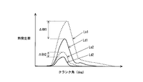
- FIG. 2 is a diagram showing the transition of the heat generation rate when the fuel burns in the cylinder 2 according to the present embodiment.
- the horizontal axis represents the crank angle
- the vertical axis represents the heat generation rate.
- solid lines Ld1 and Ld2 indicate heat generation rates when only light oil is burned
- broken lines La1 and La2 are when the same amount of light oil and CNG are burned as indicated by solid lines Ld1 and Ld2. Shows the heat release rate.
- the solid line Ld1 and the broken line La1 indicate the heat generation rate when the light oil injected from the light oil injector 8 is relatively large.
- the solid line Ld2 and the broken line La2 indicate that the light oil injected from the light oil injector 8 is relatively small. The heat generation rate in the case is shown.
- CNG Since CNG has very low ignitability, even if it is compressed in the cylinder 2 during the compression stroke, it hardly ignites. Therefore, as described above, the combustion of CNG is performed using light oil as an ignition source. That is, CNG is combusted by the heat generated by self-ignition and combustion when light oil is compressed.
- combustion of CNG is promoted as the amount of heat generated by burning light oil increases, that is, as the heat generation rate when light oil burns increases.
- the more the combustion of CNG is promoted the more heat is generated by the combustion of CNG. Therefore, the heat generation rate when light oil and CNG burn is increased.
- the magnitude of the heat generation rate peak difference ⁇ RH corresponds to the magnitude of the heat generation rate when CNG burns. That is, the greater the heat generation rate peak difference ⁇ RH, the greater the heat generation rate when CNG burns.
- FIG. 3 is a diagram showing the relationship between the heat generation rate peak difference ⁇ RH and the amount of unburned fuel component (HC) discharged from the internal combustion engine 1 according to the present embodiment.
- the horizontal axis represents the heat generation rate peak difference ⁇ RH
- the vertical axis represents the HC emission amount.
- the solid line L1 indicates the HC emission amount during low load operation
- the solid line L2 indicates the HC emission amount during medium load operation
- the solid line L3 indicates the HC emission amount during high load operation. Show.
- the broken line has shown the upper limit of the tolerance
- the heat generation rate when light oil and CNG are combusted in the internal combustion engine 1 that is, the heat generation rate (actual heat generation rate) when fuel is actually combusted in the internal combustion engine 1 is based on the detection value of the in-cylinder pressure sensor 30. Can be calculated. However, when light oil and CNG are mixed and burned, each of the heat generation rate resulting from the combustion of light oil and the heat generation rate resulting from the combustion of CNG is calculated based on the detection value of the in-cylinder pressure sensor 30. It is difficult.
- the heat generation rate (hereinafter referred to as the light oil heat generation rate) when it is assumed that only the light oil injected from the light oil injector 8 is burned is estimated based on the injection amount of the light oil, the operating state of the internal combustion engine 1, and the like. can do.
- the peak value of the actual heat generation rate is calculated based on the detection value of the in-cylinder pressure sensor 30, and the light oil heat generation rate is estimated based on the injection amount of light oil and the operating state of the internal combustion engine 1. .
- the heat generation rate peak difference ⁇ RH is calculated by subtracting the light oil heat generation rate peak value from the peak value of the actual heat generation rate, and the light oil injection amount from the light oil injector 8 is calculated based on the heat generation rate peak difference ⁇ RH. Adjust.
- the light oil injection amount from the light oil injector 8 is adjusted so that the heat release rate peak difference ⁇ RH becomes a predetermined target value.
- the predetermined target value is a value set in advance based on an experiment or the like as a value in which the discharge amount of the unburned fuel component is within the allowable range and the consumption amount of the light oil is also within the allowable range.
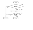
- FIG. 4 is a flowchart showing a flow of fuel injection control when light oil and CNG are mixed and burned in the internal combustion engine 1 according to this embodiment. This flow is stored in advance in the ECU 20 and is repeatedly executed by the ECU 20.
- step S101 it is determined whether or not the combustion mode in the internal combustion engine 1 is a mixed combustion of light oil and CGN. If a negative determination is made in step S101, the execution of this flow is temporarily terminated.
- step S102 the peak value RHd of the light oil heat generation rate is calculated based on the light oil injection amount from the light oil injector 8 and the operating state of the internal combustion engine 1.
- the relationship between the light oil injection amount from the light oil injector 8, the operating state of the internal combustion engine 1, and the peak value RHd of the light oil heat generation rate is stored in advance in the ECU 20 as a map or a function.
- step S102 the light oil heat release peak value RHd is calculated using the map or function.
- step S103 the peak value RHa of the actual heat generation rate is calculated based on the detection value of the in-cylinder pressure sensor 30.
- the relationship between the in-cylinder pressure and the actual heat generation rate is stored in advance in the ECU 20 as a map or a function.
- step S103 the peak value RHa of the actual heat generation rate is calculated using the map or function.
- step S104 the heat generation rate peak difference ⁇ RH is calculated by subtracting the light oil heat generation rate peak value RHd calculated in step S102 from the actual heat generation rate peak value RHa calculated in step S103.
- step S105 it is determined whether or not the heat release rate peak difference ⁇ RH is the same as a predetermined target value ⁇ RHt.
- the target value ⁇ RHt of the heat release rate peak difference is a value that is changed according to the operating state of the internal combustion engine 1.
- the relationship between the target value ⁇ RHt of the heat release rate peak difference and the operating state of the internal combustion engine 1 is stored in advance in the ECU 20 as a map or a function. Then, the target value ⁇ RHt of the heat release rate peak difference is set using the map or function.
- step S105 If an affirmative determination is made in step S105, this flow is temporarily terminated. In this case, the light oil injection amount from the light oil injector 8 is maintained at the current value. In step S105, even if the heat generation rate peak difference ⁇ RH is not the same as the predetermined target value ⁇ RHt, an affirmative determination may be made as long as the value is within an allowable range from the target value ⁇ RHt.
- step S105 determines whether or not the heat release rate peak difference ⁇ RH is greater than a predetermined target value ⁇ RHt. If an affirmative determination is made in step S106, then in step S107, the light oil injection amount Qd from the light oil injector 8 is decreased. The amount of decrease at this time is predetermined.
- step S108 it is determined whether or not the reduced light oil injection amount Qd is equal to or greater than a predetermined lower limit value Qdlimit.
- the lower limit value Qdlimit of the light oil injection amount is a value determined based on experiments or the like as a threshold value of the light oil injection amount that can ensure stable combustion.
- the lower limit value Qdlimit of the light oil injection amount is stored in the ECU 20 in advance.
- step S108 If an affirmative determination is made in step S108, then the process of step S102 is executed again. On the other hand, if a negative determination is made in step S108, the execution of this flow is temporarily terminated. In this case, the light oil injection amount from the light oil injector 8 is returned to the value before being decreased in step S107.
- step S106 If a negative determination is made in step S106, it can be determined that the heat release rate peak difference ⁇ RH is smaller than a predetermined target value ⁇ RHt. In this case, next, in step S109, the light oil injection amount Qd from the light oil injector 8 is increased. The amount of increase at this time is predetermined. After the light oil injection amount Qd is increased, the process of step S102 is executed again.
- the multi-fuel internal combustion engine according to the present invention is not limited to an internal combustion engine that uses light oil and CNG as fuel.
- the present invention can also be applied to a multi-fuel internal combustion engine that uses other self-ignitable fuels (for example, heavy oil or kerosene) and other fuels that require ignition assistance (for example, gasoline or hydrogen).
- the ECU 20 that executes step S102 in the above flow corresponds to a first heat generation amount estimation unit according to the present invention.
- ECU20 which performs step S103 in the said flow is equivalent to the actual heat generation amount calculation part which concerns on this invention.
- the ECU 20 that executes steps S107 and S109 corresponds to the first fuel supply amount adjusting unit according to the present invention.
- FIG. 5 is a part of a flowchart showing a modified example of the flow of fuel injection control in the case where light oil and CNG are mixed and burned in the internal combustion engine 1 according to the present embodiment. Steps other than steps S201 and S202 in this flow are the same as the steps in the flowchart shown in FIG. Therefore, only the processing in steps S201 and S202 will be described, and the description of the processing in other steps will be omitted. In FIG. 5, the illustration of steps after step S102 is omitted.
- step S101 if an affirmative determination is made in step S101, next in step S201, based on the intake air amount detected by the air flow meter 25, the light oil injection amount, and the CNG injection amount, the mixture gas in the cylinder 2 is determined.
- the equivalent ratio ⁇ a is calculated.
- the equivalence ratio ⁇ a of the air-fuel mixture in the cylinder 2 is smaller than a predetermined threshold value ⁇ 0.
- the predetermined threshold value ⁇ 0 is a value set as a lower limit value of an equivalence ratio in which CNG can be combusted stably.
- the threshold value ⁇ 0 is obtained based on experiments or the like, and is stored in the ECU 20 in advance.
- step S202 If an affirmative determination is made in step S202, the process of step S102 is then executed. On the other hand, if a negative determination is made in step S202, the execution of this flow is temporarily terminated.
- the necessity for adjusting the light oil injection amount is low. According to the above flow, the adjustment of the light oil injection amount can be performed only when the operation state of the internal combustion engine 1 is in the operation region where the combustion amount of CNG becomes unstable.
- Example 2 The schematic configuration of the internal combustion engine according to the present embodiment and its fuel system and intake / exhaust system is the same as the schematic configuration of the internal combustion engine according to the first embodiment and its fuel system and intake / exhaust system.
- the CNG injection from the CNG injector 9 is stopped, and the combustion mode in the internal combustion engine 1 is switched to a mode in which only light oil is burned.
- Judgment whether the property of CNG is inferior or not is made based on the increase amount of the actual heat generation rate when the light oil injection amount is increased when light oil and CNG are mixed and burned in the internal combustion engine 1. .
- the combustion amount of the CNG will not increase as much as the CNG property is normal. . Accordingly, the amount of increase in the actual heat generation rate is small.
- the predetermined increase amount is a threshold value for the increase amount of the actual heat generation rate at which it can be determined that the CNG property is normal.
- the predetermined increase amount is obtained based on an experiment or the like as a value corresponding to the increase amount when the light oil injection amount is increased, and is stored in the ECU 20 in advance.
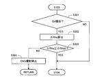
- FIG. 6 is a part of a flowchart showing a flow of fuel injection control when light oil and CNG are mixed and burned according to the present embodiment. Steps other than steps S301 to S304 in this flow are the same as the steps in the flowchart shown in FIG. For this reason, only the processing of steps S301 to S304 will be described, and description of the processing of other steps will be omitted. In FIG. 6, illustrations of steps before step S103 and steps after step S104 are omitted.
- step S103 it is determined in step 301 whether or not the light oil injection amount Qd from the light oil injector 8 has been increased, that is, whether or not step S109 has been performed. If a negative determination is made in step S301, then the process of step S104 is executed.
- step S301 If an affirmative determination is made in step S301, then in step S302, an increase amount ⁇ RHa of the actual heat generation rate before and after the increase in the light oil injection amount in step S109 is calculated.
- step S303 it is determined whether or not the actual heat generation rate increase amount ⁇ RHa is equal to or larger than a predetermined increase amount ⁇ RHa0.
- step S303 If an affirmative determination is made in step S303, the process of step S104 is then executed. On the other hand, if a negative determination is made in step S303, then in step S304, CNG injection from the CNG injector 9 is stopped, and the combustion mode in the internal combustion engine 1 is switched to a mode in which only light oil is burned. In this case, the light oil injection amount Qd from the light oil injector 8 is further increased to compensate for the CNG injection amount.
- step S304 in the above flow the CNG injection from the CNG injector 9 does not necessarily have to be stopped. That is, when the deterioration of the combustion state in the internal combustion engine 1 can be suppressed by reducing the CNG injection amount, the injection amount may be reduced while continuing the CNG injection from the CNG injector 9. In this case as well, the light oil injection amount Qd from the light oil injector 8 is further increased to compensate for the decrease in the CNG injection amount.
- the ECU 20 that executes step S304 in the above flow corresponds to the second fuel supply amount adjusting unit according to the present invention.
Landscapes
- Engineering & Computer Science (AREA)
- Chemical & Material Sciences (AREA)
- Combustion & Propulsion (AREA)
- Mechanical Engineering (AREA)
- General Engineering & Computer Science (AREA)
- Oil, Petroleum & Natural Gas (AREA)
- Output Control And Ontrol Of Special Type Engine (AREA)
- Combined Controls Of Internal Combustion Engines (AREA)
- Fuel-Injection Apparatus (AREA)
- Electrical Control Of Air Or Fuel Supplied To Internal-Combustion Engine (AREA)
Abstract
Priority Applications (5)
| Application Number | Priority Date | Filing Date | Title |
|---|---|---|---|
| EP11860468.5A EP2682588B1 (fr) | 2011-03-04 | 2011-03-04 | Système de commande d'alimentation en carburant destiné à un moteur à combustion interne polycarburant |
| PCT/JP2011/055096 WO2012120598A1 (fr) | 2011-03-04 | 2011-03-04 | Système de commande d'alimentation en carburant destiné à un moteur à combustion interne polycarburant |
| JP2013503249A JP5569644B2 (ja) | 2011-03-04 | 2011-03-04 | 多種燃料内燃機関の燃料供給制御システム |
| CN201180069011.XA CN103429874B (zh) | 2011-03-04 | 2011-03-04 | 多燃料内燃机的燃料供给控制系统 |
| US14/002,807 US9334812B2 (en) | 2011-03-04 | 2011-03-04 | Fuel supply control system for multi-fuel internal combustion engine |
Applications Claiming Priority (1)
| Application Number | Priority Date | Filing Date | Title |
|---|---|---|---|
| PCT/JP2011/055096 WO2012120598A1 (fr) | 2011-03-04 | 2011-03-04 | Système de commande d'alimentation en carburant destiné à un moteur à combustion interne polycarburant |
Publications (1)
| Publication Number | Publication Date |
|---|---|
| WO2012120598A1 true WO2012120598A1 (fr) | 2012-09-13 |
Family
ID=46797608
Family Applications (1)
| Application Number | Title | Priority Date | Filing Date |
|---|---|---|---|
| PCT/JP2011/055096 Ceased WO2012120598A1 (fr) | 2011-03-04 | 2011-03-04 | Système de commande d'alimentation en carburant destiné à un moteur à combustion interne polycarburant |
Country Status (5)
| Country | Link |
|---|---|
| US (1) | US9334812B2 (fr) |
| EP (1) | EP2682588B1 (fr) |
| JP (1) | JP5569644B2 (fr) |
| CN (1) | CN103429874B (fr) |
| WO (1) | WO2012120598A1 (fr) |
Cited By (1)
| Publication number | Priority date | Publication date | Assignee | Title |
|---|---|---|---|---|
| JP2016183670A (ja) * | 2015-03-06 | 2016-10-20 | マン・ディーゼル・アンド・ターボ・エスイー | 点火流体インジェクタを機能点検するための方法および制御装置 |
Families Citing this family (11)
| Publication number | Priority date | Publication date | Assignee | Title |
|---|---|---|---|---|
| CN103502610B (zh) * | 2011-05-13 | 2016-08-17 | 丰田自动车株式会社 | 内燃机的控制装置以及方法 |
| JP5892144B2 (ja) * | 2013-11-13 | 2016-03-23 | トヨタ自動車株式会社 | 内燃機関の制御装置 |
| DK2998547T3 (da) | 2014-09-19 | 2020-10-26 | Caterpillar Motoren Gmbh & Co | Styring af en intern forbrændingsmotor, der drives på gasformigt brændstof |
| ITUB20152149A1 (it) * | 2015-07-14 | 2017-01-14 | Marmorini Luca Ditta Individuale | Metodo di controllo della combustione in un motore a combustione interna |
| ITUA20161899A1 (it) * | 2016-03-22 | 2017-09-22 | Marmorini Luca Ditta Individuale | Metodo di controllo della combustione di un motore a combustione interna ad accensione per compressione con controllo della reattivita' mediante la temperatura di iniezione |
| KR20180034495A (ko) * | 2015-07-14 | 2018-04-04 | 마르모토르스 에스.알.엘. | 분사 온도를 통한 반응도 제어로 압축착화 내부 연소 엔진의 연소를 제어하는 방법 |
| CN105090938A (zh) * | 2015-09-14 | 2015-11-25 | 中国能源建设集团广东省电力设计研究院有限公司 | 多燃料燃机的燃料处理及供应方法 |
| GB2559361A (en) * | 2017-02-02 | 2018-08-08 | Comb Order Ltd | Improvements to operations of engines |
| CN111051670B (zh) * | 2017-08-18 | 2022-03-29 | 瓦锡兰芬兰有限公司 | 控制多气缸内燃发动机中燃料燃烧的方法和配置为控制多气缸内燃活塞发动机中的燃烧过程的计算机控制系统 |
| US11015539B2 (en) * | 2019-09-30 | 2021-05-25 | Ford Global Technologies, Llc | Systems and methods for reducing exhaust valve degradation |
| JP2023053506A (ja) * | 2021-10-01 | 2023-04-13 | マツダ株式会社 | エンジンシステム、及び、エンジンの制御方法 |
Citations (6)
| Publication number | Priority date | Publication date | Assignee | Title |
|---|---|---|---|---|
| JPH08158980A (ja) | 1994-12-06 | 1996-06-18 | Mitsubishi Motors Corp | 補助燃料着火式ガスエンジン及びその稼働方法 |
| JP2001065398A (ja) * | 1999-08-26 | 2001-03-13 | Denso Corp | 内燃機関用燃料噴射装置 |
| JP2001355471A (ja) * | 2000-06-15 | 2001-12-26 | Nissan Motor Co Ltd | 圧縮自己着火式内燃機関 |
| JP2007170345A (ja) * | 2005-12-26 | 2007-07-05 | Toyota Motor Corp | 内燃機関の燃焼異常検出装置 |
| JP2008121641A (ja) * | 2006-11-15 | 2008-05-29 | Toyota Motor Corp | 多種燃料内燃機関 |
| JP2008215204A (ja) * | 2007-03-05 | 2008-09-18 | Toyota Motor Corp | 内燃機関の熱発生率のシミュレーション方法、内燃機関のトルクモデル作成方法および内燃機関のトルク推定方法 |
Family Cites Families (12)
| Publication number | Priority date | Publication date | Assignee | Title |
|---|---|---|---|---|
| US6095102A (en) * | 1998-10-02 | 2000-08-01 | Caterpillar Inc. | Dual fuel engine which creates a substantially homogeneous mixture of gaseous fuel, air, and pilot fuel during a compression stroke |
| US6598584B2 (en) * | 2001-02-23 | 2003-07-29 | Clean Air Partners, Inc. | Gas-fueled, compression ignition engine with maximized pilot ignition intensity |
| WO2004022959A1 (fr) * | 2002-09-09 | 2004-03-18 | Toyota Jidosha Kabushiki Kaisha | Dispositif de commande de moteur a combustion interne |
| CA2444163C (fr) | 2003-10-01 | 2007-01-09 | Westport Research Inc. | Methode et appareil de controle de la qualite de la combustion dans un moteur a combustion interne a gaz |
| JP4081819B2 (ja) * | 2004-05-06 | 2008-04-30 | 株式会社デンソー | 燃料噴射システム |
| JP4779975B2 (ja) * | 2007-01-10 | 2011-09-28 | 株式会社デンソー | エンジン制御装置 |
| JP4760802B2 (ja) * | 2007-08-20 | 2011-08-31 | 株式会社デンソー | 燃料噴射制御装置及び燃料噴射制御システム |
| JP4625111B2 (ja) * | 2008-05-19 | 2011-02-02 | 本田技研工業株式会社 | 内燃機関の燃料制御装置 |
| EP2423494A4 (fr) * | 2009-04-22 | 2012-09-12 | Toyota Motor Co Ltd | Dispositif de commande de moteur à combustion interne |
| WO2011040139A1 (fr) * | 2009-09-30 | 2011-04-07 | 株式会社日立製作所 | Système de moteur à reformeur |
| WO2011048676A1 (fr) * | 2009-10-21 | 2011-04-28 | トヨタ自動車株式会社 | Dispositif de commande de combustion pour moteur à combustion interne |
| US8473180B2 (en) * | 2010-03-10 | 2013-06-25 | GM Global Technology Operations LLC | On-board fuel property detection using pattern recognition and power spectral analysis of cylinder pressure signal |
-
2011
- 2011-03-04 WO PCT/JP2011/055096 patent/WO2012120598A1/fr not_active Ceased
- 2011-03-04 JP JP2013503249A patent/JP5569644B2/ja not_active Expired - Fee Related
- 2011-03-04 EP EP11860468.5A patent/EP2682588B1/fr not_active Not-in-force
- 2011-03-04 CN CN201180069011.XA patent/CN103429874B/zh not_active Expired - Fee Related
- 2011-03-04 US US14/002,807 patent/US9334812B2/en not_active Expired - Fee Related
Patent Citations (6)
| Publication number | Priority date | Publication date | Assignee | Title |
|---|---|---|---|---|
| JPH08158980A (ja) | 1994-12-06 | 1996-06-18 | Mitsubishi Motors Corp | 補助燃料着火式ガスエンジン及びその稼働方法 |
| JP2001065398A (ja) * | 1999-08-26 | 2001-03-13 | Denso Corp | 内燃機関用燃料噴射装置 |
| JP2001355471A (ja) * | 2000-06-15 | 2001-12-26 | Nissan Motor Co Ltd | 圧縮自己着火式内燃機関 |
| JP2007170345A (ja) * | 2005-12-26 | 2007-07-05 | Toyota Motor Corp | 内燃機関の燃焼異常検出装置 |
| JP2008121641A (ja) * | 2006-11-15 | 2008-05-29 | Toyota Motor Corp | 多種燃料内燃機関 |
| JP2008215204A (ja) * | 2007-03-05 | 2008-09-18 | Toyota Motor Corp | 内燃機関の熱発生率のシミュレーション方法、内燃機関のトルクモデル作成方法および内燃機関のトルク推定方法 |
Non-Patent Citations (1)
| Title |
|---|
| See also references of EP2682588A4 |
Cited By (1)
| Publication number | Priority date | Publication date | Assignee | Title |
|---|---|---|---|---|
| JP2016183670A (ja) * | 2015-03-06 | 2016-10-20 | マン・ディーゼル・アンド・ターボ・エスイー | 点火流体インジェクタを機能点検するための方法および制御装置 |
Also Published As
| Publication number | Publication date |
|---|---|
| US9334812B2 (en) | 2016-05-10 |
| JPWO2012120598A1 (ja) | 2014-07-07 |
| EP2682588A1 (fr) | 2014-01-08 |
| CN103429874B (zh) | 2016-08-24 |
| EP2682588A4 (fr) | 2014-09-10 |
| EP2682588B1 (fr) | 2015-10-07 |
| US20130345950A1 (en) | 2013-12-26 |
| CN103429874A (zh) | 2013-12-04 |
| JP5569644B2 (ja) | 2014-08-13 |
Similar Documents
| Publication | Publication Date | Title |
|---|---|---|
| JP5569644B2 (ja) | 多種燃料内燃機関の燃料供給制御システム | |
| KR101693895B1 (ko) | 복합 착화방식의 디젤-가솔린 혼합연소엔진과 그 제어방법 및 복합 착화방식의 디젤-가솔린 혼합연소시스템 | |
| US8516991B2 (en) | Multi-fuel internal combustion engine | |
| KR101704064B1 (ko) | 복합 착화방식의 디젤-가솔린 혼합연소엔진과 그 제어방법 및 복합 착화방식의 디젤-가솔린 혼합연소시스템 | |
| JP5590226B2 (ja) | 多種燃料内燃機関の制御システム | |
| JP5783036B2 (ja) | 内燃機関 | |
| CN103502610A (zh) | 内燃机的控制装置以及方法 | |
| CN103080509A (zh) | 内燃机 | |
| JP2008274905A (ja) | 多種燃料内燃機関の燃焼制御装置 | |
| JP5846207B2 (ja) | 多種燃料内燃機関の制御システム | |
| CN103415687B (zh) | 多燃料内燃机的控制装置 | |
| KR101381034B1 (ko) | 디젤-천연가스 혼소 엔진 시스템 및 이의 제어방법 | |
| JP5556956B2 (ja) | 内燃機関の制御装置及び方法 | |
| WO2012046311A1 (fr) | Dispositif de commande de combustion pour moteur à combustion interne | |
| JP2017008900A (ja) | 天然ガスエンジン及び天然ガスエンジンの運転方法 | |
| WO2012114482A1 (fr) | Système de commande de moteur à combustion interne | |
| JP2012255422A (ja) | 内燃機関の制御装置 | |
| JP5614296B2 (ja) | デュアルフューエルエンジンの燃料供給システム | |
| JP2013032742A (ja) | 圧縮着火式内燃機関の燃料供給装置 | |
| JP2006144560A (ja) | 内燃機関の制御装置 |
Legal Events
| Date | Code | Title | Description |
|---|---|---|---|
| 121 | Ep: the epo has been informed by wipo that ep was designated in this application |
Ref document number: 11860468 Country of ref document: EP Kind code of ref document: A1 |
|
| ENP | Entry into the national phase |
Ref document number: 2013503249 Country of ref document: JP Kind code of ref document: A |
|
| WWE | Wipo information: entry into national phase |
Ref document number: 14002807 Country of ref document: US |
|
| NENP | Non-entry into the national phase |
Ref country code: DE |
|
| WWE | Wipo information: entry into national phase |
Ref document number: 2011860468 Country of ref document: EP |