WO2012121313A1 - 回転コネクタ装置 - Google Patents
回転コネクタ装置 Download PDFInfo
- Publication number
- WO2012121313A1 WO2012121313A1 PCT/JP2012/055902 JP2012055902W WO2012121313A1 WO 2012121313 A1 WO2012121313 A1 WO 2012121313A1 JP 2012055902 W JP2012055902 W JP 2012055902W WO 2012121313 A1 WO2012121313 A1 WO 2012121313A1
- Authority
- WO
- WIPO (PCT)
- Prior art keywords
- rotator
- flat cable
- cable
- retainer
- dummy
- Prior art date
- Legal status (The legal status is an assumption and is not a legal conclusion. Google has not performed a legal analysis and makes no representation as to the accuracy of the status listed.)
- Ceased
Links
Images



Classifications
-
- H—ELECTRICITY
- H01—ELECTRIC ELEMENTS
- H01R—ELECTRICALLY-CONDUCTIVE CONNECTIONS; STRUCTURAL ASSOCIATIONS OF A PLURALITY OF MUTUALLY-INSULATED ELECTRICAL CONNECTING ELEMENTS; COUPLING DEVICES; CURRENT COLLECTORS
- H01R13/00—Details of coupling devices of the kinds covered by groups H01R12/70 or H01R24/00 - H01R33/00
- H01R13/46—Bases; Cases
- H01R13/52—Dustproof, splashproof, drip-proof, waterproof, or flameproof cases
-
- B—PERFORMING OPERATIONS; TRANSPORTING
- B60—VEHICLES IN GENERAL
- B60R—VEHICLES, VEHICLE FITTINGS, OR VEHICLE PARTS, NOT OTHERWISE PROVIDED FOR
- B60R16/00—Electric or fluid circuits specially adapted for vehicles and not otherwise provided for; Arrangement of elements of electric or fluid circuits specially adapted for vehicles and not otherwise provided for
- B60R16/02—Electric or fluid circuits specially adapted for vehicles and not otherwise provided for; Arrangement of elements of electric or fluid circuits specially adapted for vehicles and not otherwise provided for electric constitutive elements
- B60R16/023—Electric or fluid circuits specially adapted for vehicles and not otherwise provided for; Arrangement of elements of electric or fluid circuits specially adapted for vehicles and not otherwise provided for electric constitutive elements for transmission of signals between vehicle parts or subsystems
- B60R16/027—Electric or fluid circuits specially adapted for vehicles and not otherwise provided for; Arrangement of elements of electric or fluid circuits specially adapted for vehicles and not otherwise provided for electric constitutive elements for transmission of signals between vehicle parts or subsystems between relatively movable parts of the vehicle, e.g. between steering wheel and column
-
- H—ELECTRICITY
- H01—ELECTRIC ELEMENTS
- H01R—ELECTRICALLY-CONDUCTIVE CONNECTIONS; STRUCTURAL ASSOCIATIONS OF A PLURALITY OF MUTUALLY-INSULATED ELECTRICAL CONNECTING ELEMENTS; COUPLING DEVICES; CURRENT COLLECTORS
- H01R35/00—Flexible or turnable line connectors, i.e. the rotation angle being limited
- H01R35/02—Flexible line connectors without frictional contact members
- H01R35/025—Flexible line connectors without frictional contact members having a flexible conductor wound around a rotation axis
Definitions
- the present invention relates to a rotary connector device that electrically connects, for example, a steering wheel side and a vehicle body side of an automobile.
- a rotary connector device mounted on a vehicle such as an automobile is configured by coaxially assembling a stator that is mainly fixed to the vehicle body side and a rotator that is assembled on the steering wheel side so as to be relatively rotatable. Furthermore, the flat cable is accommodated in the accommodation space comprised with a stator and a rotator.
- This flat cable is used to electrically connect electrical components such as a horn module, airbag module, or audio control module installed on the steering wheel side to the vehicle body side power supply.
- Patent Document 1 a device provided with a retainer that is arranged on the bottom surface of the accommodation space and rotates and guides a flat cable around the rotation axis of the steering wheel is proposed.
- the retainer 40 is provided with a plurality of rotating rollers 45 and a pressing guide portion 46 erected in the vicinity of the rotating rollers 45. And in the accommodation space S, this retainer 40 assists rotation of the flat cable C in winding and rewinding, so that the rotary connector device can smoothly rotate following the steering operation. .
- the flat cable C is wound around the outer winding portion Co that is wound along the inner peripheral surface of the outer cylindrical body 32 of the stator 30 and one rotating roller 45 that is pivotally supported by the retainer 40.
- the reversing portion Cr that is hooked and U-turned and the inner winding portion Ci wound around the outer peripheral surface of the inner peripheral cylindrical portion 22 of the rotator 20 are configured.
- the reverse portion Cr of the flat cable C may be worn and a malfunction may occur.
- the rotator 20 rotates clockwise, if foreign matter such as dust is mixed in the contact portion between the inverted portion Cr of the flat cable C and the pressing guide portion 46, the inverted portion Cr rubs against the foreign matter, so that the flat cable There is a risk that C may wear out and cause a problem.
- an object of the present invention is to provide a rotary connector device that can reliably maintain an electrical connection between a rotator and a stator even if foreign matter such as dust is mixed.
- the present invention relates to a rotator comprising an annular rotating side ring plate and a cylindrical inner peripheral cylindrical portion formed on the inner peripheral edge of the rotating side ring plate, an annular fixed side ring plate, and an outer side of the fixed side ring plate.
- a stator composed of a cylindrical outer peripheral cylindrical portion formed on the periphery is coaxially fitted so as to be relatively rotatable in a clockwise direction and a counterclockwise direction, and the rotation side ring plate and the inner peripheral cylindrical portion of the rotator And a stationary ring plate and an outer peripheral cylindrical portion of the stator, and an annular retainer that pivotally supports a plurality of rotating rollers is placed on the bottom of the accommodation space, and the retainer in the accommodation space
- a rotary connector that accommodates at least one flat cable having an inversion portion for electrically connecting the rotator side and the stator side and reversing the winding direction at an upper portion thereof so as to be capable of being wound and unwound.
- the upper end of the retainer in the housing space is connected and fixed at one end in the longitudinal direction to the rotator side, and the other end is connected and fixed to the stator side, and is wound directly around one of the rotating rollers. While having a reversing part that reverses the direction, and holding a flexible and elastic dummy cable that can be wound and unwound along the rotating roller and the flat cable, A pressing guide portion that allows direct pressing of the inverted portion of the dummy cable is provided.
- the dummy cable is formed to have substantially the same width as the flat cable, and is a strip that does not electrically connect the retainer and the rotator, or a flat cable that has a conductor but does not electrically connect the rotator and the stator. be able to.
- the dummy cable may be formed of only an insulating member that does not include a conductor inside and has an insulating property.
- the present invention it is possible to provide a rotary connector device that can reliably maintain an electrical connection between a rotator and a stator even if foreign matter such as dust is mixed.
- the dummy cable non-electrically connects the rotator side and the stator side.
- repulsive force due to the elasticity of the dummy cable is generated in the radial direction of the stator and rotator at both ends in the length direction of the inverted portion of the dummy cable. Specifically, a repulsive force is generated radially outward at the stator side end of the inverted portion of the dummy cable, while a repulsive force is generated radially inward at the rotator side end. As a result, the dummy cable is wound and rewound while being pressed in the radial direction of the rotator side and the stator side. Can abut.
- the retainer can be reliably rotated by the dummy cable and can be rotated more smoothly following the rotation of the rotator. And since a retainer rotates smoothly with a dummy cable, it can wind and rewind, without applying an excessive load to a flat cable, and can prevent the disconnection of a flat cable, etc.
- the reversing portion of the flat cable is arranged in the middle in the circumferential direction between the rotating rollers, and the retainer rotates on the retainer near the rotating roller following the rotation of the rotator.
- a regulating portion that regulates the radial movement of the dummy cable or the flat cable by providing an interval greater than a moving range in which the inverted portion of the flat cable moves in the circumferential direction. it can.
- the inversion portion of the flat cable when the rotator is stationary, the inversion portion of the flat cable can be arranged with a sufficient distance from the restricting portion of the retainer. Therefore, even if a rotator rotates, it can prevent that the inversion part of a flat cable contacts with the control part of a retainer.
- the reversing portion of the flat cable does not contact the restricting portion of the retainer, so that the retainer can smoothly rotate following the rotation of the rotator.
- the flat cable can be worn or damaged even if the rotator rotates while foreign matter such as dust is mixed in by arranging the reversing part of the flat cable with a sufficient distance from the restricting part of the retainer. Therefore, the electrical connection between the rotator and the stator can be more reliably maintained.
- the length of the dummy cable in the longitudinal direction can be formed shorter than the length of the flat cable in the longitudinal direction.
- the dummy cable can be wound around the rotator while being superimposed on the flat cable.
- the slack of the flat cable generated at the time of winding and unwinding due to the repulsive force at the inverted portion of the dummy cable can be suppressed, and the flat cable can be prevented from being worn or damaged due to contact with the retainer or the like.
- the length of the dummy cable in the longitudinal direction shorter than the length in the longitudinal direction of the flat cable, it is possible to more reliably prevent the flat cable from coming into contact with the retainer restricting portion, etc. Even if it is mixed, the electrical connection between the rotator and the stator can be more reliably maintained.
- a rotary connector device that can reliably maintain an electrical connection between a rotator and a stator even if foreign matter such as dust is mixed.
- FIG. 2 is a cross-sectional view taken along line AA in FIG.
- the top view which shows the state in the accommodation space at the time of rotator rotation.
- the top view of the steering roll connector which shows the state which removed the rotator in another embodiment.
- the top view which shows the pressing guide part of a prior art.
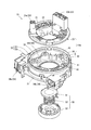
- FIG. 1 shows a perspective view of the appearance of the steering roll connector 10
- FIG. 2 shows an exploded perspective view of the steering roll connector 10 in an exploded state
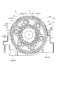
- FIG. 3 shows the present embodiment with the rotator 20 removed.
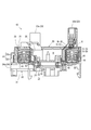
- FIG. 4 shows a cross-sectional view taken along the line AA in FIG.
- the steering roll connector 10 of the present embodiment includes a cable housing 10a, a retainer 40, and a rotation lock structure 50 as shown in FIGS.
- the cable housing 10 a is configured in a substantially cylindrical shape in which an insertion hole H penetrating in the rotation axis direction (vertical direction in FIG. 4) of the steering is formed in the center portion in plan view. ing.
- the insertion hole H is formed with a diameter that allows insertion of a steering shaft (not shown) protruding from a steering column (not shown).
- the cable housing 10a includes a stator 30 and a rotator 20 that can rotate relative to each other.
- a steering wheel (not shown) for performing a rotation operation is fixed to the upper end portion of the steering shaft.
- the rotation lock structure 50 includes a lock body 51, a spring receiving sleeve 53, and a return spring 52 interposed between the lock body 51 and the spring receiving sleeve 53.
- the rotator 20 By pushing up the spring receiving sleeve 53 against the urging force of the return spring 52, the rotator 20 can be locked by the lock body 51 so as not to rotate relative to the stator 30, or the boss portion of the core metal of the steering wheel By inserting (not shown), the lock by the lock body 51 can be released so as to allow relative rotation freely.
- the rotator 20 includes a rotation-side ring plate 21 that functions as a top plate formed in an annular shape, and a cylindrical inner peripheral cylindrical portion that extends downward from the inner periphery of the rotation-side ring plate 21. 22.
- the rotator 20 is fixed to the steering wheel and rotates integrally with the steering wheel. Specifically, the rotator 20 can rotate about the same axis as the rotation axis of the steering wheel.
- the rotator 20 includes a rotator-side connector 23 that rotates integrally with the rotation of the rotator 20.
- the rotator side connector 23 includes a first rotator side connector 23a and a second rotator side connector 23b.
- the first rotator side connector 23a and the second rotator side connector 23b are arranged so that the connector connection port faces upward at a predetermined interval in the circumferential direction of the rotation side ring plate 21.
- the rotator-side connectors 23 are connected to cables (not shown) drawn from an electric circuit such as a horn switch and an airbag unit arranged on the steering wheel, for example.
- the stator 30 is fixed to an appropriate member on the vehicle body side, for example, a combination bracket switch (not shown) disposed inside the steering column, and is attached so as to be rotatable relative to the steering wheel.
- the stator 30 includes a fixed-side ring plate 31 that functions as an annular bottom plate, and a cylindrical outer peripheral cylindrical portion 32 that extends upward from the outer peripheral edge of the fixed-side ring plate 31.
- the outer peripheral edge of the stationary ring plate 31 and the lower end of the outer peripheral cylindrical portion 32 are integrally formed.
- the outer peripheral cylindrical portion 32 includes a cylindrical outer outer peripheral cylindrical portion 32 o and a cylindrical inner outer peripheral cylindrical portion 32 i having a slightly smaller diameter than the outer outer peripheral cylindrical portion 32 o.
- the outer peripheral cylindrical portion 32o and the inner peripheral cylindrical portion 32i are configured in a radial two-layer structure arranged concentrically so as to face each other in the radial direction.
- a guide protruding piece that protrudes inward in the radial direction (inward radial direction) and guides a flat cable C and a dummy cable D described later from above, as shown in FIG. 33 is formed in a bowl shape.
- stator 30 includes a stator side connector 34.
- the stator side connector 34 includes a first stator side connector 34a and a second stator side connector 34b.
- the first stator side connector 34a and the second stator side connector 34b are arranged outside the outer peripheral cylindrical portion 32 (outer outer peripheral cylindrical portion 32o) so that the respective connector connection ports face the same direction at a predetermined interval. Yes.
- stator side connectors 34 are respectively connected to cables (not shown) drawn from the electric circuit on the vehicle body side in the lower column cover (not shown).
- the stationary side ring plate 31 of the stator 30 is connected to the rotator 20 as shown in FIGS.
- the outer circumferential cylindrical portion 32 of the stator 30 faces the inner circumferential cylindrical portion 22 of the rotator 20 on the outer side in the radial direction and constitutes an accommodation space S. .
- the retainer 40 In this accommodation space S, the retainer 40, the flat cable C, and the dummy cable D are accommodated.
- the retainer 40 is composed of a plurality of rotating rollers 45 and a base ring 41, and can be rotated around the rotation axis of the rotator 20 on the bottom surface of the stator 30 constituting the accommodation space S. It is mounted on.
- the base ring 41 includes a plate-like base ring main body portion 42 having an annular shape in plan view, a roller support protrusion 43, a radial direction restricting portion 44, and a pressing guide portion 46.
- the base ring main body 42 is placed so as to be slidable in the rotational direction with respect to the stationary side ring plate 31, and is configured to be rotatable relative to the stator 30.
- the roller support protrusion 43 protrudes upward in the circumferential direction of the base ring main body 42 so that the rotation roller 45 can be pivotally supported at equal intervals.
- the radial restriction part 44 includes a first radial restriction part 44a and a second radial restriction part that are formed in different shapes depending on the path of the flat cable C and the dummy cable D between the roller support protrusions 43 adjacent in the circumferential direction. 44 b, a third radial direction restricting portion 44 c, and a fourth radial direction restricting portion 44 d, and is erected upward with respect to the base ring main body portion 42.
- the first radial direction restricting portion 44a is a dummy cable D (a dummy cable to be described later) whose direction is reversed so as to be wound around one of the rotating rollers 45 pivotally supported by the plurality of roller support protrusions 43 in a U shape. It is erected at a position close to the convex surface side in the longitudinal direction of the inverted portion Dr) of D.
- the 1st radial direction control part 44a is the flat cable C (inner winding part Ci of the flat cable C mentioned later) wound so that the outer peripheral surface of the inner peripheral cylinder part 22 of the rotator 20 in planar view, and a dummy cable D (inner winding portion Di of dummy cable D to be described later) is formed in a substantially concave shape in plan view having an opening on the outer side so as to guide from the outer side.
- a pressing guide portion 46 is integrally formed on the end surface of the first radial direction restricting portion 44a facing the reverse portion Dr of the dummy cable D.
- the pressing guide portion 46 is formed in a substantially arcuate shape so as to follow the inverted portion Dr of the dummy cable D in plan view.
- the second radial direction restricting portion 44b is adjacent to the roller support protruding portion 43 adjacent in the circumferential direction across the first radial direction restricting portion 44a from the roller support protruding portion 43 around which the reverse portion Dr of the dummy cable D is wound. Further, the roller support protrusion 43 is interposed between the first radial direction restricting portion 44a and a position facing the first radial direction restricting portion 44a in the circumferential direction.
- the 2nd radial direction regulation part 44b is formed in the planar view substantially concave shape which has an opening in the roller support protrusion 43 side which adjoins in planar view. Further, the second radial direction restricting portion 44b guides the inner winding portion Ci of the flat cable C and the inner winding portion Di of the dummy cable D from the outer diameter side.
- the third radial direction restricting portion 44c is adjacent to the second radial direction restricting portion 44b and the circumferential direction in which the second radial direction restricting portion 44b is erected from the roller support protrusion 43 adjacent to the second radial direction restricting portion 44b. Between the roller support protrusion 43 and the roller support protrusion 43, the position is close to the roller support protrusion 43.
- the 3rd radial direction control part 44c is formed in the planar view substantially concave shape which has an opening in the roller support protrusion 43 side which adjoins in planar view.
- the third radial direction restricting portion 44c guides the inner winding portion Ci of the flat cable C and the inner winding portion Di of the dummy cable D from the outer diameter side.
- the fourth radial direction restricting portion 44d is erected between adjacent roller support protrusions 43 that are not provided with the first radial direction restricting portion 44a, the second radial direction restricting portion 44b, and the third radial direction restricting portion 44c. is doing.
- the fourth radial direction restricting portion 44d includes an inner winding portion Ci of the flat cable C and an inner winding portion Di of the dummy cable D that are wound along the outer peripheral surface of the inner peripheral cylindrical portion 22 of the rotator 20 in plan view. It is formed in a substantially concave shape in a plan view having an opening on the outside of the diameter so as to guide from the outside of the diameter.
- Rotating rollers 45 are respectively supported by roller support protrusions 43 and are provided so as to be rotatable about an axis parallel to the rotation axis of the rotator 20.
- the flat cable C is a flexible band-shaped transmission line in which a plurality of flat conductors are arranged in parallel at a predetermined pitch and covered with an insulating covering, and is accommodated while being wound in the accommodation space S.
- the first rotator side connector 23a and the first stator side connector 34a are electrically connected to each other.
- one end of the flat cable C in the length direction is connected to the first rotator side connector 23a, and the other end is connected to the first stator side connector 34a.
- the flat cable C is supported by the retainer 40 that is rotatably mounted on the fixed-side ring plate 31 in the accommodating space S inside the cable housing 10a, and is accommodated in a wound state.
- the flat cable C is drawn into the accommodation space S from the first stator side connector 34a in the accommodation space S, and as shown in FIGS. 3 and 4, the outer peripheral cylindrical portion 32 of the stator 30 outside the retainer 40.
- An outer winding portion Co that is wound along the inner peripheral surface of the (inner outer cylindrical portion 32i) is formed.
- the flat cable C is oriented so as to be wound in a U-shape around the rotating roller 45 adjacent to the second radial direction restricting portion 44b in the middle of the length direction.
- Inverted portion Cr is formed by inverting.
- the inversion part Cr is arrange
- the flat cable C includes an inner winding portion Ci that is wound along the outer peripheral surface of the inner peripheral cylindrical portion 22 of the rotator 20 inside the retainer 40 by the front end side in the length direction from the reversing portion Cr. Yes.
- the flat cable C is finally pulled out of the accommodation space S and connected to the first rotator side connector 23a.
- the dummy cable D is a flexible belt-like cable having elasticity covered with an insulating covering, and is formed shorter than the length of the flat cable C in the length direction. Then, the dummy cable D is wound and accommodated in the accommodation space S in a set of two overlapping with the flat cable C, and the rotator 20 and the stator 30 are non-electrically connected.
- one end of the dummy cable D in the length direction is connected and fixed near the first rotator side connector 23a, and the other end is connected and fixed near the first stator side connector 34a.
- the dummy cable D is drawn into the accommodation space S from the first stator side connector 34a in a state of a set of two overlapping the flat cable C in the accommodation space S, as shown in FIGS.
- An outer winding portion Do wound around the inner peripheral surface of the outer peripheral cylindrical portion 32 (inner outer peripheral cylindrical portion 32i) of the stator 30 is formed outside the retainer 40.
- the dummy cable D is reversed in the middle so as to be wound in a U-shape around the rotating roller 45 adjacent to the pressing guide portion 46.
- Inverted portion Dr is formed.
- the dummy cable D is in the state of a set of two overlapped with the flat cable C by the front end side in the length direction from the reversing portion Dr, and the outer peripheral surface of the inner peripheral cylindrical portion 22 of the rotator 20 inside the retainer 40.
- the inner winding portion Di wound so as to extend along the line is configured.
- the dummy cable D is finally pulled out of the accommodation space S and connected and fixed near the first rotator side connector 23a.
- the flat cable C and the dummy cable D are wound as a set of two in the accommodation space S as described above, but in FIGS. 3 and 4, only one is wound in a simplified manner. It is shown in a state.
- FIG. 5 shows a plan view of a state in the accommodation space S when the rotator 20 is rotated
- FIG. 5A shows a state in which the rotator 20 is rotated clockwise (X direction in FIG. 5).
- FIG. 5B shows a state in which the rotator 20 is rotated counterclockwise (Y direction in FIG. 5).
- the state of the inverted portion Cr of the flat cable C and the inverted portion Dr of the dummy cable D when the rotator 20 is stationary is indicated by a two-dot chain line. Further, the flat cable C and the dummy cable D are wound in a superposed manner as a pair in the accommodation space S as described above, but in FIG. Show.
- the reversing portion Cr rotates appropriately with the retainer 40 so as to follow the change in the balance of the winding state between the outer winding portion Co and the inner winding portion Ci.
- the inversion portion Dr rotates appropriately with the retainer 40 so as to follow the change in the balance of the winding state between the outer winding portion Do and the inner winding portion Di.
- the reverse portion Dr of the dummy cable D is As shown to 5 (a), before the inversion part Cr of the flat cable C contacts the 3rd radial direction control part 44c, it is pressed by the pressing guide part 46.
- FIG. 5 (a) shows that before the inversion part Cr of the flat cable C contacts the 3rd radial direction control part 44c, it is pressed by the pressing guide part 46.
- the retainer 40 rotates clockwise (X direction in FIG. 5) so as to follow the rotation of the rotator 20 by the pressing force.
- the reversing portion Cr of the flat cable C and the reversing portion Dr of the dummy cable D are wound around the outer winding portion Co of the flat cable C and the outer winding portion Do of the dummy cable D while rotating together with the retainer 40.
- the inversion portion Cr of the flat cable C rotates with the retainer 40 while maintaining a constant interval with respect to the second radial direction regulating portion 44b and the third radial direction regulating portion 44c.
- the reversing portion Cr rotates appropriately with the retainer 40 so as to follow the change in the balance of the winding state between the outer winding portion Co and the inner winding portion Ci.
- the inversion portion Dr rotates appropriately with the retainer 40 so as to follow the change in the balance of the winding state between the outer winding portion Do and the inner winding portion Di.
- the reverse portion Dr of the dummy cable D is As shown in FIG. 5B, the reversal portion Cr of the flat cable C comes into contact with the rotating roller 45 before coming into contact with the second radial direction restricting portion 44b.
- the reverse portion Dr of the dummy cable D is pulled counterclockwise (Y direction in FIG. 5) along the rotation roller 45, so that the retainer 40 counterclockwise so as to follow the rotation of the rotator 20. Rotate.
- the inversion portion Cr of the flat cable C and the inversion portion Dr of the dummy cable D are wound around the inner winding portion Ci of the flat cable C and the inner winding portion Di of the dummy cable while rotating together with the retainer 40.
- the inversion portion Cr of the flat cable C rotates with the retainer 40 while maintaining a constant interval with respect to the second radial direction regulating portion 44b and the third radial direction regulating portion 44c.
- the steering roll connector 10 having the above-described configuration capable of realizing the above-described operation can reliably maintain the electrical connection between the rotator 20 and the stator 30 even when foreign matter such as dust is mixed.
- the inverted portion Dr of the dummy cable D is The retainer 40 can be rotated clockwise by the pressing force that is pressed against the pressing guide portion 46.
- the reverse portion Dr of the dummy cable D pressed against the pressing guide portion 46 can be prevented from buckling or bending.
- repulsive force due to the elasticity of the dummy cable D is generated in the radial direction of the rotator 20 and the stator 30 at both ends in the length direction of the inverted portion Dr of the dummy cable D. Specifically, a repulsive force is generated radially outward at the end of the inverted portion Dr of the dummy cable D toward the stator 30 side, while a repulsive force is generated radially inward at the end of the rotator 20 side.
- the dummy cable D is wound and rewound while being pressed against the rotator 20 and the stator 30, so that the slack of the dummy cable D can be suppressed and the dummy cable D can be surely brought into contact with the pressing guide portion 46. .
- the retainer 40 can be reliably rotated by the dummy cable D due to the elasticity of the dummy cable D, and can be rotated more smoothly following the rotation of the rotator 20. And since the retainer 40 rotates smoothly with the dummy cable D, winding and unwinding can be performed without applying an excessive load to the flat cable C, and disconnection of the flat cable C can be prevented. .
- the dummy cable D is overlaid on the flat cable C, the slack of the flat cable C that occurs at the time of winding and unwinding can be suppressed by the repulsive force at the reverse portion Dr of the dummy cable D. Further, it is possible to prevent the flat cable C from being worn or damaged by contacting the retainer 40 or the like.
- the radial direction restricting portion 44 is erected with a space larger than the range in which the reverse portion Dr of the flat cable D moves in the circumferential direction.
- the reversal portion Cr of the flat cable C is disposed with a sufficient distance from the second radial direction restricting portion 44b and the third radial direction restricting portion 44c of the retainer 40. Can do. Therefore, even if the rotator 20 rotates, the reverse portion Cr of the flat cable C can be prevented from coming into contact with the second radial direction restricting portion 44b and the third radial direction restricting portion 44c of the retainer 40.
- the inverted portion Cr of the flat cable C is rubbed against the second radial direction regulating portion 44b and the third radial direction regulating portion 44c of the retainer 40. Since it is not wound and unwound, the flat cable C can be prevented from being worn or damaged.
- the retainer 40 can smoothly rotate following the rotation of the rotator 20, and the flat cable C can be wound and unwound without applying an excessive load.
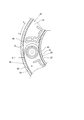
- FIG. 6 shows a plan view of the steering roll connector 10 with the rotator 20 removed in the second embodiment.
- the same components as those in the first embodiment are given the same reference numerals, and detailed description thereof is omitted.
- the steering roll connector 10 has a configuration in which the flat cable F is added to the above-described first embodiment in the accommodation space S. Further, by adding the flat cable F, the configuration of the radial direction restricting portion 44 of the retainer 40 is different from that of the first embodiment.
- the retainer 40 is close to the rotating roller 45 around which the reverse portion Dr of the dummy cable D is wound, and is positioned at a position facing the first radial direction restricting portion 44a in the circumferential direction with the rotating roller 45 interposed therebetween.
- a third radial direction restricting portion 44c is erected.
- the third radial direction restricting portion 44c, the rotating roller 45 around which the reversal portion Dr of the dummy cable D is wound, and the rotating roller 45 adjacent in the circumferential direction are positioned close to the rotating roller 45.
- the two radial direction restricting portion 44b is erected.
- the flat cable F is a flexible band-shaped transmission line in which a plurality of flat conductors are arranged in parallel at a predetermined pitch and covered with an insulating covering, and the length of the dummy cable D is It is shorter than the length. Then, the flat cable F is accommodated in the accommodation space S in a state where the three are overlapped and wound together with the dummy cable D and the flat cable C, and the second rotator side connector 23b and the second stator side connector 34b are mutually connected. Electrically connected.
- one end of the flat cable F in the length direction is connected to the second rotator side connector 23b, and the other end is connected to the second stator side connector 34b.
- the flat cable F is supported by a retainer 40 that is rotatably mounted on the stationary ring plate 31 in the accommodation space S inside the cable housing 10a, and is overlapped with the flat cable C and the dummy cable D. Housed in a wound state.
- the flat cable F is drawn into the accommodation space S from the second stator side connector 34b in the accommodation space S, and a set of three cables superimposed on the flat cable C and the dummy cable D as shown in FIG.
- an outer winding portion Fo that is wound outside the retainer 40 along the inner peripheral surface of the outer peripheral cylindrical portion 32 (inner outer peripheral cylindrical portion 32i) of the stator 30 is configured.
- the flat cable C, the dummy cable D, and the flat cable F are wound together so that the flat cable C comes into contact with the inner peripheral surface of the inner outer peripheral cylindrical portion 32i of the stator 30 in a set of three in which the flat cable C, the dummy cable D, and the flat cable F are stacked. Yes.
- the flat cable F is in the middle of the length direction from the rotating roller 45 around which the inversion part Dr of the dummy cable D is wound to the 1st radial direction control part 44a.
- the inversion part Fr is arrange
- the inner peripheral cylinder portion of the rotator 20 inside the retainer 40 in a state of a set of three superposed on the flat cable C and the dummy cable D by the front end side in the length direction from the inversion portion Fr.
- An inner winding portion Fi that is wound along the outer peripheral surface 22 is configured.
- the flat cable F is finally pulled out from the accommodation space S and connected to the second rotator side connector 23b.
- the flat cable C, the dummy cable D, and the flat cable F are wound in such a manner that the flat cable C comes into contact with the outer peripheral surface of the inner peripheral cylindrical portion 22 of the rotator 20 in a set of three in which the flat cable C, the flat cable F are overlapped in this order. .
- the flat cables C and F and the dummy cable D are wound as a set of three in the accommodation space S as described above, but in FIG. 6, only one is wound in a simplified manner. It is shown in a state.
- the reverse portion Fr of the flat cable F is connected to the third reverse portion Cr as in the reverse portion Cr of the flat cable C. Since a sufficient interval is secured in the circumferential direction with respect to the radial restricting portion 44c, the inversion of the dummy cable D is performed before the inversion portion Fr of the flat cable F contacts the third radial restricting portion 44c. The portion Dr is pressed against the pressing guide portion 46.
- the pressing force causes the retainer 40 to rotate clockwise so as to follow the rotation of the rotator 20.
- the inversion portion Fr of the flat cable F rotates with the retainer 40 while maintaining a constant interval with respect to the second radial direction restricting portion 44b and the third radial direction restricting portion 44c.
- the inversion portion Fr of the flat cable F rotates with the retainer 40 while maintaining a constant interval with respect to the second radial direction restricting portion 44b and the third radial direction restricting portion 44c.
- the dummy cable D is pressed before the flat cables C and F contact the second radial direction restricting portion 44b and the third radial direction restricting portion 44c.
- the electrical connection between the rotator 20 and the stator 30 can be reliably maintained even if foreign matter such as dust is mixed.
- the flat cable F is superimposed on the dummy cable D, the repulsive force at the reversal portion Fr of the flat cable F suppresses slack and the like that occur when the dummy cable D and the flat cable C are wound and unwound. be able to. Therefore, it is possible to prevent the flat cable C and the flat cable F from coming into contact with the radial direction restricting portion 44 of the retainer 40 and being worn or damaged.
- the dummy cable D can function as an insulator between the flat cable C and the flat cable F.
- the insulating coverings of the flat cable C and the flat cable F can be formed in a thinner film, and the steering roll connector 10 can be reduced in weight and cost.
- the dummy cable D is overlapped between the flat cables C and F.
- the method of overlapping the flat cables C and F and the dummy cable D is not limited to this, and the flat cable C is not limited thereto.
- F may be overlapped with a dummy cable D.
- the reversal portion Fr of the flat cable F and the reversal portion Cr of the flat cable C are arranged across the reversal portion Dr of the dummy cable D.
- the arrangement of each inversion portion is not limited to this.
- the reverse portion Dr of the dummy cable D, the reverse portion Cr of the flat cable C, and the reverse portion Fr of the flat cable F may be arranged in this order.
- the dummy cable D is connected and fixed at one end in the length direction in the vicinity of the first rotator side connector 23a and the other end in the vicinity of the first stator side connector 34a. It is not limited to.
- the end portion of the dummy cable D in the length direction may be connected and fixed to the inner peripheral cylindrical portion 22 of the rotator 20 or the outer peripheral cylindrical portion 32 of the stator 30. Or you may make it connect to the connector terminal of the edge part in the length direction of the flat cables C and F, etc.
- the rotary connector device of the present invention corresponds to the steering roll connector 10 of the embodiment
- the restriction portions correspond to the second radial direction restriction portion 44b and the third radial direction restriction portion 44c,
- the present invention is not limited only to the configuration of the above-described embodiment, and many embodiments can be obtained.
Landscapes
- Engineering & Computer Science (AREA)
- Mechanical Engineering (AREA)
- Steering Controls (AREA)
- Electric Cable Arrangement Between Relatively Moving Parts (AREA)
Priority Applications (4)
| Application Number | Priority Date | Filing Date | Title |
|---|---|---|---|
| JP2012534176A JP5654025B2 (ja) | 2011-03-09 | 2012-03-08 | 回転コネクタ装置 |
| CN201280004108.7A CN103262366B (zh) | 2011-03-09 | 2012-03-08 | 旋转连接器装置 |
| EP12755404.6A EP2685571B1 (de) | 2011-03-09 | 2012-03-08 | Drehbare steckverbinderanordnung |
| US14/021,584 US9124022B2 (en) | 2011-03-09 | 2013-09-09 | Rotatable connector device |
Applications Claiming Priority (2)
| Application Number | Priority Date | Filing Date | Title |
|---|---|---|---|
| JP2011-050944 | 2011-03-09 | ||
| JP2011050944 | 2011-03-09 |
Related Child Applications (1)
| Application Number | Title | Priority Date | Filing Date |
|---|---|---|---|
| US14/021,584 Continuation US9124022B2 (en) | 2011-03-09 | 2013-09-09 | Rotatable connector device |
Publications (1)
| Publication Number | Publication Date |
|---|---|
| WO2012121313A1 true WO2012121313A1 (ja) | 2012-09-13 |
Family
ID=46798268
Family Applications (1)
| Application Number | Title | Priority Date | Filing Date |
|---|---|---|---|
| PCT/JP2012/055902 Ceased WO2012121313A1 (ja) | 2011-03-09 | 2012-03-08 | 回転コネクタ装置 |
Country Status (5)
| Country | Link |
|---|---|
| US (1) | US9124022B2 (de) |
| EP (1) | EP2685571B1 (de) |
| JP (1) | JP5654025B2 (de) |
| CN (1) | CN103262366B (de) |
| WO (1) | WO2012121313A1 (de) |
Cited By (2)
| Publication number | Priority date | Publication date | Assignee | Title |
|---|---|---|---|---|
| CN112103740A (zh) * | 2020-09-01 | 2020-12-18 | 山西中航锦恒科技有限公司 | 一种扁平电缆与转子同步转动结构及其安装方法 |
| JP2021012783A (ja) * | 2019-07-04 | 2021-02-04 | 古河電気工業株式会社 | 回転コネクタ装置および回転コネクタ装置の製造方法 |
Families Citing this family (12)
| Publication number | Priority date | Publication date | Assignee | Title |
|---|---|---|---|---|
| JP5224404B2 (ja) * | 2010-03-30 | 2013-07-03 | 古河電気工業株式会社 | 回転コネクタ装置 |
| US9327938B2 (en) * | 2013-02-14 | 2016-05-03 | Haworth, Inc. | Cable retractor |
| KR101558978B1 (ko) * | 2015-06-18 | 2015-10-13 | (주)금오전자 | 케이블 인출 유닛 어셈블리 |
| KR101627224B1 (ko) * | 2014-10-28 | 2016-06-03 | 세종공업 주식회사 | 다기능 포지션 홀더 및 이를 갖춘 커넥터 |
| CN107429324B (zh) | 2015-04-01 | 2019-12-17 | 古河电气工业株式会社 | 扁平轧制铜箔、柔性扁平电缆、旋转连接器和扁平轧制铜箔的制造方法 |
| JP6928831B2 (ja) * | 2017-07-26 | 2021-09-01 | 古河電気工業株式会社 | 回転コネクタ装置のフラットケーブルを構成する導体の製造方法 |
| US11034374B2 (en) * | 2017-08-10 | 2021-06-15 | Toyoda Gosei Co., Ltd. | Steering wheel |
| JP7296366B2 (ja) * | 2018-03-30 | 2023-06-22 | 古河電気工業株式会社 | 回転コネクタ装置およびその固定体 |
| CN109532707B (zh) * | 2018-11-13 | 2020-04-17 | 浙江阳明汽车部件有限公司 | 一种汽车时钟弹簧 |
| WO2020121741A1 (ja) * | 2018-12-13 | 2020-06-18 | 古河電気工業株式会社 | 回転コネクタ装置 |
| WO2021193502A1 (ja) * | 2020-03-24 | 2021-09-30 | 古河電気工業株式会社 | ケーブル巻き取り装置、及びスライドシート用フラットケーブル配索構造 |
| CN116891166A (zh) * | 2023-06-30 | 2023-10-17 | 深圳康诺思腾科技有限公司 | 外部旋转关节和手术机器人 |
Citations (4)
| Publication number | Priority date | Publication date | Assignee | Title |
|---|---|---|---|---|
| WO1999029004A1 (en) * | 1997-11-28 | 1999-06-10 | Furukawa Electric Co., Ltd. | Rotary connector |
| JP2003197339A (ja) | 2001-12-26 | 2003-07-11 | Furukawa Electric Co Ltd:The | 回転コネクタ |
| JP2004222369A (ja) * | 2003-01-10 | 2004-08-05 | Furukawa Electric Co Ltd:The | 回転コネクタ装置 |
| JP2005158635A (ja) * | 2003-11-28 | 2005-06-16 | Furukawa Electric Co Ltd:The | 難燃フラットケーブルおよび難燃フラットケーブルを用いた回転コネクタ |
Family Cites Families (10)
| Publication number | Priority date | Publication date | Assignee | Title |
|---|---|---|---|---|
| JP3050688B2 (ja) * | 1992-02-20 | 2000-06-12 | 古河電気工業株式会社 | 回転体と固定体間の伝送装置 |
| JPH0945446A (ja) * | 1995-07-27 | 1997-02-14 | Tokai Rika Co Ltd | ステアリングロールコネクタ |
| JP3676146B2 (ja) * | 1999-10-22 | 2005-07-27 | 古河電気工業株式会社 | 回転コネクタ |
| US6780032B2 (en) * | 2002-10-07 | 2004-08-24 | Tyco Electronics Corporation | Loop back clockspring connector having high current capacity |
| JP4355229B2 (ja) * | 2004-02-12 | 2009-10-28 | アルプス電気株式会社 | 回転コネクタ |
| JP2008021555A (ja) * | 2006-07-13 | 2008-01-31 | Alps Electric Co Ltd | 回転コネクタ |
| JP4448882B2 (ja) * | 2008-01-08 | 2010-04-14 | アルプス電気株式会社 | 回転コネクタ |
| JP5123070B2 (ja) * | 2008-06-19 | 2013-01-16 | ナイルス株式会社 | 回転コネクタ装置 |
| JP5624972B2 (ja) * | 2011-10-31 | 2014-11-12 | 古河電気工業株式会社 | 回転コネクタ装置 |
| WO2014017649A1 (ja) * | 2012-07-26 | 2014-01-30 | 古河電気工業株式会社 | 回転コネクタ装置 |
-
2012
- 2012-03-08 CN CN201280004108.7A patent/CN103262366B/zh not_active Expired - Fee Related
- 2012-03-08 JP JP2012534176A patent/JP5654025B2/ja active Active
- 2012-03-08 WO PCT/JP2012/055902 patent/WO2012121313A1/ja not_active Ceased
- 2012-03-08 EP EP12755404.6A patent/EP2685571B1/de not_active Not-in-force
-
2013
- 2013-09-09 US US14/021,584 patent/US9124022B2/en active Active
Patent Citations (4)
| Publication number | Priority date | Publication date | Assignee | Title |
|---|---|---|---|---|
| WO1999029004A1 (en) * | 1997-11-28 | 1999-06-10 | Furukawa Electric Co., Ltd. | Rotary connector |
| JP2003197339A (ja) | 2001-12-26 | 2003-07-11 | Furukawa Electric Co Ltd:The | 回転コネクタ |
| JP2004222369A (ja) * | 2003-01-10 | 2004-08-05 | Furukawa Electric Co Ltd:The | 回転コネクタ装置 |
| JP2005158635A (ja) * | 2003-11-28 | 2005-06-16 | Furukawa Electric Co Ltd:The | 難燃フラットケーブルおよび難燃フラットケーブルを用いた回転コネクタ |
Non-Patent Citations (1)
| Title |
|---|
| See also references of EP2685571A4 |
Cited By (3)
| Publication number | Priority date | Publication date | Assignee | Title |
|---|---|---|---|---|
| JP2021012783A (ja) * | 2019-07-04 | 2021-02-04 | 古河電気工業株式会社 | 回転コネクタ装置および回転コネクタ装置の製造方法 |
| JP7335736B2 (ja) | 2019-07-04 | 2023-08-30 | 古河電気工業株式会社 | 回転コネクタ装置および回転コネクタ装置の製造方法 |
| CN112103740A (zh) * | 2020-09-01 | 2020-12-18 | 山西中航锦恒科技有限公司 | 一种扁平电缆与转子同步转动结构及其安装方法 |
Also Published As
| Publication number | Publication date |
|---|---|
| CN103262366A (zh) | 2013-08-21 |
| CN103262366B (zh) | 2015-08-19 |
| EP2685571A4 (de) | 2014-08-20 |
| EP2685571B1 (de) | 2017-05-03 |
| US20140011374A1 (en) | 2014-01-09 |
| JP5654025B2 (ja) | 2015-01-14 |
| JPWO2012121313A1 (ja) | 2014-07-17 |
| US9124022B2 (en) | 2015-09-01 |
| EP2685571A1 (de) | 2014-01-15 |
Similar Documents
| Publication | Publication Date | Title |
|---|---|---|
| JP5654025B2 (ja) | 回転コネクタ装置 | |
| JP5184716B2 (ja) | 回転コネクタ装置 | |
| JP5117528B2 (ja) | 回転コネクタ装置 | |
| JP5053433B2 (ja) | 回転コネクタ装置 | |
| JP5117595B2 (ja) | 回転コネクタ装置 | |
| JPH0321544A (ja) | 配線装置 | |
| WO2011122469A1 (ja) | 回転コネクタ装置 | |
| JP2011258546A5 (de) | ||
| CN102823082B (zh) | 旋转连接器装置 | |
| JP5041449B2 (ja) | 回転コネクタ装置 | |
| CN103262365B (zh) | 旋转连接器装置 | |
| KR100311246B1 (ko) | 회전 커넥터 | |
| JPH0878125A (ja) | ハンドルとステアリングコラム間の電気的接続装置 | |
| WO2017104548A1 (ja) | 回転コネクタ |
Legal Events
| Date | Code | Title | Description |
|---|---|---|---|
| ENP | Entry into the national phase |
Ref document number: 2012534176 Country of ref document: JP Kind code of ref document: A |
|
| 121 | Ep: the epo has been informed by wipo that ep was designated in this application |
Ref document number: 12755404 Country of ref document: EP Kind code of ref document: A1 |
|
| NENP | Non-entry into the national phase |
Ref country code: DE |
|
| REEP | Request for entry into the european phase |
Ref document number: 2012755404 Country of ref document: EP |
|
| WWE | Wipo information: entry into national phase |
Ref document number: 2012755404 Country of ref document: EP |