WO2012127532A1 - 関節装置の駆動方法 - Google Patents
関節装置の駆動方法 Download PDFInfo
- Publication number
- WO2012127532A1 WO2012127532A1 PCT/JP2011/001704 JP2011001704W WO2012127532A1 WO 2012127532 A1 WO2012127532 A1 WO 2012127532A1 JP 2011001704 W JP2011001704 W JP 2011001704W WO 2012127532 A1 WO2012127532 A1 WO 2012127532A1
- Authority
- WO
- WIPO (PCT)
- Prior art keywords
- gear
- motor
- link
- output shaft
- differential
- Prior art date
- Legal status (The legal status is an assumption and is not a legal conclusion. Google has not performed a legal analysis and makes no representation as to the accuracy of the status listed.)
- Ceased
Links
Images






Classifications
-
- B—PERFORMING OPERATIONS; TRANSPORTING
- B25—HAND TOOLS; PORTABLE POWER-DRIVEN TOOLS; MANIPULATORS
- B25J—MANIPULATORS; CHAMBERS PROVIDED WITH MANIPULATION DEVICES
- B25J9/00—Program-controlled manipulators
- B25J9/10—Program-controlled manipulators characterised by positioning means for manipulator elements
- B25J9/102—Gears specially adapted therefor, e.g. reduction gears
- B25J9/1025—Harmonic drives
-
- B—PERFORMING OPERATIONS; TRANSPORTING
- B25—HAND TOOLS; PORTABLE POWER-DRIVEN TOOLS; MANIPULATORS
- B25J—MANIPULATORS; CHAMBERS PROVIDED WITH MANIPULATION DEVICES
- B25J17/00—Joints
-
- F—MECHANICAL ENGINEERING; LIGHTING; HEATING; WEAPONS; BLASTING
- F16—ENGINEERING ELEMENTS AND UNITS; GENERAL MEASURES FOR PRODUCING AND MAINTAINING EFFECTIVE FUNCTIONING OF MACHINES OR INSTALLATIONS; THERMAL INSULATION IN GENERAL
- F16H—GEARING
- F16H49/00—Other gearings
- F16H49/001—Wave gearings, e.g. harmonic drive transmissions
-
- Y—GENERAL TAGGING OF NEW TECHNOLOGICAL DEVELOPMENTS; GENERAL TAGGING OF CROSS-SECTIONAL TECHNOLOGIES SPANNING OVER SEVERAL SECTIONS OF THE IPC; TECHNICAL SUBJECTS COVERED BY FORMER USPC CROSS-REFERENCE ART COLLECTIONS [XRACs] AND DIGESTS
- Y10—TECHNICAL SUBJECTS COVERED BY FORMER USPC
- Y10T—TECHNICAL SUBJECTS COVERED BY FORMER US CLASSIFICATION
- Y10T74/00—Machine element or mechanism
- Y10T74/19—Gearing
-
- Y—GENERAL TAGGING OF NEW TECHNOLOGICAL DEVELOPMENTS; GENERAL TAGGING OF CROSS-SECTIONAL TECHNOLOGIES SPANNING OVER SEVERAL SECTIONS OF THE IPC; TECHNICAL SUBJECTS COVERED BY FORMER USPC CROSS-REFERENCE ART COLLECTIONS [XRACs] AND DIGESTS
- Y10—TECHNICAL SUBJECTS COVERED BY FORMER USPC
- Y10T—TECHNICAL SUBJECTS COVERED BY FORMER US CLASSIFICATION
- Y10T74/00—Machine element or mechanism
- Y10T74/20—Control lever and linkage systems
- Y10T74/20207—Multiple controlling elements for single controlled element
- Y10T74/20305—Robotic arm
- Y10T74/20317—Robotic arm including electric motor
Definitions
- the present invention relates to a robot joint device and a drive control method for a joint portion of a robot. Specifically, the present invention relates to a robot joint apparatus having flexibility (back drivability) with respect to external force and a drive control method for the robot joint section.
- service robots are required to be lightweight, capable of producing torque, and capable of high-precision operation control.
- a combination of a servo motor and a differential speed reducer is employed for the joint portion of almost all service robots.
- the differential reducer is compact, lightweight, highly accurate, and capable of a high reduction ratio, and is an indispensable element for joint drive of a service robot.
- Such differential reduction gears can realize high-precision driving without backlash in a compact space, but on the other hand, the back drivability is very low.
- a large static friction acts on the meshing of the gears in the differential reduction gear. Therefore, unless a considerably large torque is applied from the output side, the joint cannot be turned from the output side against the static friction in the differential reduction gear.
- Non-Patent Document 1 there is a technique called dithering.
- dithering This means that the static friction does not work in a pseudo manner by causing the motor to vibrate at a high frequency with a small amplitude when the joint is stationary.
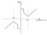
- the friction model is disclosed in Non-Patent Document 1, for example. This is shown in FIG.
- FIG. 1 There are other friction models, but the basic trends are generally the same. As can be seen from this friction model, large friction (static friction) works in the low-speed region, and once the friction is reduced to a certain speed, the friction force (viscous friction) increases as the speed increases. It is.
- Non-Patent Document 2 it is examined how much the friction at the start of operation is reduced by dithering. This Non-Patent Document 2 demonstrates that dithering requires less external force at the start of operation and reports that dithering may improve back drivability. Yes.
- a technique for reducing friction by such dithering is applied in Patent Document 1, for example.
- An object of the present invention is to provide a joint device suitable for a robot joint and having improved back drivability, and a driving method thereof.
- the driving method of the joint device of the present invention is: A driving method for a joint device that includes a drive unit and a differential reducer between a first link and a second link, and controls driving of the first link and the second link as a joint,
- the differential reducer has an inner gear, an intermediate gear and an outer gear;
- the drive unit has a first motor and a second motor, The first motor and the second motor are fixedly provided on the first link, Connecting the output shaft of the first motor to any one of the internal gear, the intermediate gear and the external gear of the differential reducer; Connecting the output shaft of the second motor to any one of the gears connected to the output shaft of the first motor among the internal gear, the intermediate gear and the external gear of the differential reducer; Of the internal gear, intermediate gear, and external gear of the differential reducer, the gear connected to the output shaft of the first motor is different from the gear connected to the output shaft of the second motor.
- the differential speed reducer is preferably a wave gear mechanism or a planetary gear mechanism.
- the relationship between the relative speed difference between the inner gear, the intermediate gear and the outer gear and the friction force is specified as a friction model, It is preferable to determine the respective rotation speeds of the first motor and the second motor so that the rotation speed ratio is such that the joint can be stationary and the friction is close to the minimum speed difference.
- the joint device of the present invention is A joint device comprising a differential speed reducer between the first link and the second link, wherein the first link and the second link are joint-driven, A first motor fixedly connected to the first link and an output shaft connected to any one of the inner gear, the intermediate gear and the outer gear of the differential reducer; A gear which is fixedly connected to the first link and whose output shaft is different from the gear connected to the output shaft of the first motor among the inner gear, the intermediate gear and the outer gear of the differential reduction gear. A second motor coupled to any one of Of the internal gear, intermediate gear, and external gear of the differential reducer, the gear connected to the output shaft of the first motor is different from the gear connected to the output shaft of the second motor. One of these is connected to the second link.
- the joint is stationary, but the gear in the differential reducer is in a relatively moving state. That is, it is possible to prevent static friction from acting in the differential reduction gear even though the joint is stationary. Thereby, since the friction in a differential reduction gear becomes small, high back drivability is securable.
- the figure which shows the structure of a wave gear apparatus The figure for demonstrating operation
- the figure which showed the differential reduction gear typically.
- the robot joint device of the present invention will be described. Before describing the configuration of the present invention, the configuration and operation of the differential reduction gear used in the robot joint device will be described. Although the configuration of the differential reduction gear is known per se, it will be briefly described because it is a premise for understanding the present invention. As an example of the differential reduction gear, a wave gear device known as Harmonic Drive (registered trademark) is taken as an example.
- Harmonic Drive registered trademark
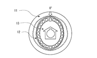
- FIG. 1 is a diagram illustrating a configuration of a wave gear device.
- 2A to 2D are diagrams for explaining the operation of the wave gear device.
- the wave gear device 10 is a mechanism that reduces the rotation of the input shaft with a very large reduction ratio (a very large reduction ratio such as several tens to hundreds) and transmits it to the output shaft.
- the wave gear device 10 includes a circular spline 11 as an outer gear, a flex spline 12 as an intermediate gear, and a wave generator 13 as an inner gear.
- Inner teeth are formed inside a storage case provided to store the wave gear device 10, thereby forming a circular spline 11 as an outer gear.
- a wave generator (internal gear) 13 is configured by arranging a plurality of pressing balls at equal intervals along the outer periphery of the elliptical cam.
- the flexspline (intermediate gear) 12 is formed of an elastic material, and a wave generator 13 is provided inside the flexspline 12 along an inner peripheral surface thereof.
- External teeth are formed on the outer periphery of the flexspline (intermediate gear) 12 so as to mesh with the circular spline 11 which is an external gear.
- the flex spline (inner gear) 12 is elastically deformed into an elliptical shape. Then, two portions corresponding to the long axis of the ellipse are pushed out to the outermost side and mesh with the circular spline 12. However, the number of teeth of the circular spline 11 is two more than the number of teeth of the flexspline 12.
- the circular spline 11 that is an outer gear is fixed, the input shaft is connected to the wave generator 13, and the output shaft is connected to the flex spline 12.
- the elliptical cam of the wave generator 13 also rotates, and the meshing position between the flexspline 12 and the circular spline 11 also rotates.
- 2A to 2D are diagrams showing a case where the circular spline 11 is fixed and the wave generator 13 is rotated once.
- the number of teeth of the flexspline 12 is two less than the number of teeth of the circular spline 11.
- the wave gear device 10 realizes a very large reduction ratio.
- the wave generator 13 is rotated with the circular spline 11 fixed.
- the circular spline 11 is connected to the driving means (motor) and rotated without fixing the circular spline 11.
- the flexspline 12 does not rotate at all from the initial position. That is, by rotating the inner gear (wave generator 13) and the outer gear (circular spline 11) at a certain speed difference, it is possible to create a state where the intermediate gear (flex spline 12) does not rotate at all.
- the differential reducer is schematically represented as shown in FIG. That is, the differential speed reducer 20 is represented by a triple box, the outermost box being the outer gear 21, the innermost box being the inner gear 23, and the box between them being the intermediate gear 22.
- the differential reduction gear is a wave gear device
- the outer gear 21 corresponds to the circular spline 11
- the intermediate gear 22 corresponds to the flex spline 12
- the inner gear 23 corresponds to the wave generator 13.
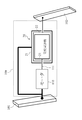
- FIG. 5 is a diagram showing a conventional robot joint 100 as a comparative example.
- the motor 110 is fixed to the first link 101, and the output shaft 111 of the motor 110 is connected to the internal gear (wave generator) 23.
- An outer gear (circular spline) 21 is fixed to the first link 101.
- the intermediate gear (flex spline) 22 is connected to the second link 102. In this state, when a current is applied to the motor 110 from a predetermined motor drive circuit (not shown), the motor 110 is rotationally driven.
- the internal gear (wave generator) 22 rotates integrally with the output shaft 111.
- the intermediate gear (flex spline) 22 rotates at a reduced speed by the meshing of the outer gear (circular spline) 21 and the intermediate gear (flex spline) 22.
- the rotation of the intermediate gear (flex spline) 22 is transmitted as an output to the second link 102, and the second link 102 is driven.
- two motors are used, and two of the three elements of the differential speed reducer 20 are continuously rotated at a predetermined speed difference. This prevents static friction from acting even when the output shaft remains stationary.
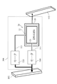
- the first pattern is shown in FIG.
- the first pattern has two motors, a first motor 210 and a second motor 220.
- the first motor 210 is fixed to the first link 101, and the output shaft 211 of the first motor 210 is connected to an internal gear (wave generator) 23 of the differential reduction gear 20.
- the second motor 220 is also fixed to the first link 101, but the output shaft 221 of the second motor 220 is connected to the outer gear (circular spline) 21 of the differential reduction gear 20.
- the second link 102 is connected to an intermediate gear (flex spline) 22 of the differential reduction gear 20.
- the intermediate gear (flex spline) 22 can be stationary by rotating the inner gear (wave generator) 23 and the outer gear (circular spline) 21 with a certain speed difference in the same direction.
- the differential reduction gear 20 can be brought into a state where static friction does not act.
- the case where the differential reduction gear 20 is the wave gear device 10 will be specifically described as an example.
- the number of teeth of the circular spline (outer gear) 11 is Zc
- the number of teeth of the flexspline (intermediate gear) 12 is Zf.
- the rotation speed of the wave generator (inner gear) 13 is Vw
- the rotation speed of the flex spline (intermediate gear) 12 is Vf
- the rotation speed of the circular spline (outer gear) 11 is Vc.
- the friction in the differential reduction gear is minimized when the joint is stationary. It is only necessary to rotate the wave generator (internal gear) 13 and the circular spline (outer gear) 11 so that a rotational speed ratio at which the joint can be stopped and a speed difference that minimizes friction is generated. For example, if a friction model is obtained as shown in FIG. 7, the rotational speed at which the joint can be kept still is obtained near the speed difference ⁇ V 1 or ⁇ V 2 at which the friction is minimized.
- the speed difference means a rotational speed difference between the wave generator (internal gear) 13 and the flexspline (intermediate gear) 12.
- a command current may be applied to each of the first motor 210 and the second motor 220 so as to realize the obtained rotation speed.
- the second motor 220 When it is desired to perform the joint operation by driving the second link 102 relative to the first link 101, the second motor 220 is simply stopped and only the first motor 210 is driven. That is, the outer gear (circular spline) 21 may be fixed and the inner gear (wave generator) 23 may be rotated. Thereby, it becomes the same joint operation as the past.
- the rotation of the intermediate gear (flex spline) 22 is generated by the relative rotation of the internal gear (wave generator) 23 and the external gear (circular spline) 21, so the internal gear (wave generator) 23 and the external gear (circular spline) 21 may be rotated in the opposite direction.
- the rotational power of the intermediate gear (flex spline) 22 can be shared between the first motor 210 and the second motor 220, so the load on the first motor 210 is reduced. Can be reduced.
- the friction in the differential reduction gear is reduced even when the joint is stationary, high back drivability can be ensured.
- the force applied to the second link 102 is easily transmitted from the output shaft of the differential reducer 20 to the input shaft.
- the joint is easily bent by the force, so that an effect of reducing the force at the time of contact is achieved. That is, a so-called soft joint can be realized.
- a person teaches by moving the robot's limbs, there is an effect that a large force is not required.
- the second pattern is shown in FIG.
- the first motor 310 is fixed to the first link 101, and the output shaft 311 of the first motor 310 is connected to the internal gear (wave generator) 23 of the differential reduction gear 20.
- the second motor 320 is also fixed to the first link 101, but the output shaft 321 of the second motor 320 is connected to the intermediate gear (flex spline) 22 of the differential reduction gear 20.
- the second link is connected to the outer gear of the differential reducer.
- the outer gear (circular spline) 21 can be stationary by rotating the inner gear (wave generator) 23 and the intermediate gear (flexspline) 22 in the opposite directions at a predetermined relative speed.
- Differential speed reducer 20 and a wave gear device 10 in the number of teeth Z f of the flexspline 12 is 200, when 202 the number of teeth Z c of the circular spline 11, the above formula becomes as follows.
- the flex spline (intermediate gear) 12 is rotated in the opposite direction by two teeth while the wave generator (internal gear) 13 rotates once, the circular spline (outer gear) 11 will not rotate.
- the flex spline (intermediate gear) 12 is rotated at 0.2 rpm in the reverse direction while the wave generator (inner gear) 13 is rotated at 20 rpm, the circular spline (outer gear) 11 is stationary without rotating. .
- the rotational speeds of the wave generator (inner gear) 13 and the flexspline (intermediate gear) 12 are set based on the friction model so that the friction in the differential reducer is minimized when the joint is stationary.
- Ask. A command current may be applied to each of the first motor 310 and the second motor 320 so as to realize the obtained rotation speed.
- the second motor 320 When it is desired to drive the second link 102 relative to the first link 101 to perform a joint operation, the second motor 320 is simply stopped and only the first motor 310 is driven. That is, the intermediate gear (flex spline) 22 may be fixed and the internal gear (wave generator) 23 may be rotated. As a result, the outer gear (circular spline) 21 rotates, so that the second link 102 is driven to perform the joint operation. Alternatively, the inner gear (wave generator) 23 and the intermediate gear (flex spline) 22 may be rotated in the same direction.
- the rotational power of the outer gear (circular spline) 21 can be shared by the first motor 310 and the second motor 320, so the load on the first motor 310 is reduced. Can be reduced.
- the differential reduction gear is a wave gear device (harmonic drive (registered trademark))
- the planetary gear apparatus is used as a differential reduction gear
- the planetary gear device 30 includes an outer gear 31, a plurality of planetary gears 32, a planetary carrier 33 that picks up the revolution of the planetary gear 32, and a planetary gear 33.
- a sun gear 34 The planetary gear 32 meshes with the sun gear 34 and the outer ring gear 31, and performs rotation and revolution.
- the outer ring gear 31 corresponds to the outer gear 21, the planetary gear 32 and the planet carrier 33 correspond to the intermediate gear 22, and the sun gear 34 corresponds to the inner gear 23.
- the first pattern and the second pattern are also possible in the planetary gear unit 30.
- the first pattern and the second pattern are also possible with the planetary gear mechanism, the case where the planetary gear device 30 is applied to the second pattern will be described. That is, the first motor 310 is fixed to the first link 101, and the output shaft 311 of the first motor 310 is connected to the internal gear (sun gear) 23 of the differential reduction gear 20.
- the second motor 320 is fixed to the first link 101, and the output shaft 321 of the second motor 320 is connected to the intermediate gear (planetary gear, planetary carrier) 22 of the differential reduction gear 20.
- the second link 102 is connected to the outer gear (outer ring gear) 21 of the differential reduction gear 20.
- the outer gear (outer ring gear) 21 can be stationary by rotating the inner gear (sun gear) 23 and the intermediate gear (planetary gear, planet carrier) 22 in the same direction at a predetermined relative speed.
- the differential reduction gear 20 can be brought into a state where static friction does not act.
- the number of teeth of the sun gear 34 is Zs
- the number of teeth of the planetary gear 32 is Zp
- the number of teeth of the outer ring gear 31 is Zo
- the rotational speed of the sun gear 34 is Vs
- the rotational speed of the planetary carrier 33 (revolution speed of the planetary gear)
- the rotational speed of the outer ring gear 31 is Vo.
- the outer ring gear 31 is not rotated.
- the planetary gear 32 is rotated (revolved) at 1 rpm in the same direction while the sun gear 34 is rotated at 3 rpm, the outer ring gear 31 is not rotated but is stationary. In this way, the friction in the differential reduction gear (planetary gear mechanism) can be reduced while the joint operation is stationary.
- the third pattern is shown in FIG.
- the first motor 410 is fixed to the first link 101, and the output shaft 411 of the first motor 410 is connected to the intermediate gear (planetary gear, planetary carrier) 22 of the differential speed reducer 20.
- the second motor 420 is also fixed to the first link 101, but the output shaft 421 of the second motor 420 is connected to the outer gear (outer ring gear) 21 of the differential reduction gear 20.
- the second link 102 is connected to an internal gear (sun gear) 23 of the differential reduction gear 20.
- the inner gear (sun gear) 23 can be stationary by rotating the intermediate gear (planetary gear, planet carrier) 22 and the outer gear (outer ring gear) 21 in the same direction at a predetermined relative speed.
- the differential reduction gear 20 can be prevented from undergoing static friction.
- the sun gear (inner gear) 34 Will not rotate.
- the sun gear 34 is stationary without rotating. In this way, the friction in the differential reduction gear (planetary gear mechanism) can be reduced while the joint operation is stationary.
- the present invention is not limited to the above-described embodiment, and can be changed as appropriate without departing from the spirit of the present invention.
- a wave gear device and a planetary gear device are exemplified, but other differential reducers can be applied. Further, all of the first pattern, the second pattern, and the third pattern can be applied to the wave gear device, and further, all of the first pattern, the second pattern, and the third pattern can be applied to the planetary gear device. is there.
Landscapes
- Engineering & Computer Science (AREA)
- Robotics (AREA)
- Mechanical Engineering (AREA)
- Manipulator (AREA)
- Retarders (AREA)
Priority Applications (5)
| Application Number | Priority Date | Filing Date | Title |
|---|---|---|---|
| US13/577,416 US8733207B2 (en) | 2011-03-23 | 2011-03-23 | Method of driving joint device |
| PCT/JP2011/001704 WO2012127532A1 (ja) | 2011-03-23 | 2011-03-23 | 関節装置の駆動方法 |
| CN201180016120.5A CN103153556B (zh) | 2011-03-23 | 2011-03-23 | 关节装置的驱动方法 |
| EP11852221.8A EP2689900B1 (de) | 2011-03-23 | 2011-03-23 | Verfahren zum antrieb einer gelenkvorrichtung |
| JP2012525781A JP5387775B2 (ja) | 2011-03-23 | 2011-03-23 | 関節装置の駆動方法 |
Applications Claiming Priority (1)
| Application Number | Priority Date | Filing Date | Title |
|---|---|---|---|
| PCT/JP2011/001704 WO2012127532A1 (ja) | 2011-03-23 | 2011-03-23 | 関節装置の駆動方法 |
Publications (1)
| Publication Number | Publication Date |
|---|---|
| WO2012127532A1 true WO2012127532A1 (ja) | 2012-09-27 |
Family
ID=46878736
Family Applications (1)
| Application Number | Title | Priority Date | Filing Date |
|---|---|---|---|
| PCT/JP2011/001704 Ceased WO2012127532A1 (ja) | 2011-03-23 | 2011-03-23 | 関節装置の駆動方法 |
Country Status (5)
| Country | Link |
|---|---|
| US (1) | US8733207B2 (de) |
| EP (1) | EP2689900B1 (de) |
| JP (1) | JP5387775B2 (de) |
| CN (1) | CN103153556B (de) |
| WO (1) | WO2012127532A1 (de) |
Cited By (2)
| Publication number | Priority date | Publication date | Assignee | Title |
|---|---|---|---|---|
| JP2014087170A (ja) * | 2012-10-24 | 2014-05-12 | Seiko Epson Corp | 電気機械装置、並びに、これを備える移動体およびロボット |
| WO2023090204A1 (ja) * | 2021-11-16 | 2023-05-25 | ソニーグループ株式会社 | 制御システム、制御装置及びアクチュエータ |
Families Citing this family (7)
| Publication number | Priority date | Publication date | Assignee | Title |
|---|---|---|---|---|
| JP6228837B2 (ja) * | 2013-12-25 | 2017-11-08 | 富士通周辺機株式会社 | マニピュレータ駆動制御装置 |
| US9371899B2 (en) * | 2014-05-27 | 2016-06-21 | Hamilton Sundstrand Corporation | Harmonic drive assembly with selective disconnect and reconnect |
| DE102015200374A1 (de) * | 2015-01-13 | 2016-07-14 | Kuka Roboter Gmbh | Getriebe, elektrische Antriebsvorrichtung und Industrieroboter |
| CN104712711B (zh) * | 2015-02-09 | 2018-05-11 | 陈志同 | 一种可用于机器人关节减速器的余弦渐开线少齿差传动装置 |
| WO2018229987A1 (ja) * | 2017-06-16 | 2018-12-20 | 株式会社ハーモニック・ドライブ・システムズ | 波動歯車装置 |
| CN108032328B (zh) * | 2017-12-18 | 2023-08-04 | 深圳市优必选科技有限公司 | 一种舵机组件、机器人关节结构及机器人 |
| CN110788847B (zh) * | 2019-11-22 | 2021-01-15 | 合肥工业大学 | 一种有辅助驱动单元的节能型工业机器人 |
Citations (3)
| Publication number | Priority date | Publication date | Assignee | Title |
|---|---|---|---|---|
| JPH08308178A (ja) * | 1995-05-08 | 1996-11-22 | Shigeto Suzuki | モーター装置 |
| JPH1149013A (ja) | 1997-08-07 | 1999-02-23 | Mitsubishi Electric Corp | 電動式パワーステアリング装置 |
| JP2009291874A (ja) * | 2008-06-04 | 2009-12-17 | Kansai Electric Power Co Inc:The | 関節装置、ロボットアーム、及び、フィンガーユニット |
Family Cites Families (30)
| Publication number | Priority date | Publication date | Assignee | Title |
|---|---|---|---|---|
| JPS61147407U (de) | 1985-02-27 | 1986-09-11 | ||
| JP2606236B2 (ja) | 1987-10-13 | 1997-04-30 | 株式会社安川電機 | 非線形摩擦補償を行った高速位置決め制御方法 |
| JP2681969B2 (ja) | 1988-02-17 | 1997-11-26 | 株式会社安川電機 | 可変構造系によるクーロン摩擦の補償方法 |
| JPH0248710A (ja) | 1988-08-11 | 1990-02-19 | Fanuc Ltd | ソフトウェアサーボにおける静摩擦補償方法 |
| JPH04257001A (ja) | 1991-02-08 | 1992-09-11 | Fanuc Ltd | ゲインスケジューリング |
| US5222409A (en) * | 1991-09-25 | 1993-06-29 | Dalakian Sergei V | Industrial robot arms |
| DE69315318D1 (de) | 1992-12-07 | 1998-01-02 | Koninkl Philips Electronics Nv | Steuerungseinrichtung |
| JPH06309008A (ja) | 1993-04-20 | 1994-11-04 | Mitsubishi Heavy Ind Ltd | サーボ制御装置 |
| JP3463355B2 (ja) | 1994-06-03 | 2003-11-05 | 株式会社安川電機 | 制御対象の特性を表す関数の定数の同定・補償方法 |
| JP2619227B2 (ja) | 1994-11-30 | 1997-06-11 | 川崎重工業株式会社 | ロボットの制御方法および装置 |
| JPH08286759A (ja) | 1995-04-14 | 1996-11-01 | Fanuc Ltd | 静摩擦を補償するロボット駆動制御方法 |
| JPH09231701A (ja) | 1996-02-21 | 1997-09-05 | Hitachi Ltd | ヘッド位置決め制御方法 |
| JP3552076B2 (ja) | 1996-06-20 | 2004-08-11 | 株式会社安川電機 | ロボット制御方法 |
| JPH11123690A (ja) | 1997-10-24 | 1999-05-11 | Denso Corp | 多関節形ロボット |
| JP4038805B2 (ja) | 1997-11-11 | 2008-01-30 | 株式会社安川電機 | 電動機の摩擦補償方法 |
| CN2389046Y (zh) * | 1999-09-30 | 2000-07-26 | 上海交通大学 | Sma丝差动驱动的转动关节臂 |
| JP2002046632A (ja) | 2000-08-07 | 2002-02-12 | Nsk Ltd | 電動パワーステアリング装置の制御装置 |
| JP3949470B2 (ja) | 2002-02-27 | 2007-07-25 | 本田技研工業株式会社 | プラントの制御装置 |
| JP2004195576A (ja) | 2002-12-17 | 2004-07-15 | Japan Science & Technology Agency | 機能性流体を用いた柔軟関節マニピュレータ |
| JP4614427B2 (ja) | 2003-08-06 | 2011-01-19 | 日産自動車株式会社 | 低摩擦摺動機構、手動変速機及び終減速機 |
| JP2005186258A (ja) * | 2003-12-26 | 2005-07-14 | Daihen Corp | 作業用ロボット |
| JP4148189B2 (ja) | 2004-06-14 | 2008-09-10 | トヨタ自動車株式会社 | 柔軟関節ロボットアームの制御装置 |
| JP4453526B2 (ja) | 2004-11-19 | 2010-04-21 | 株式会社安川電機 | サーボ制御装置 |
| JP2007001444A (ja) | 2005-06-24 | 2007-01-11 | Toyota Motor Corp | 車両用駆動装置 |
| JP2007085530A (ja) * | 2005-09-26 | 2007-04-05 | Nabtesco Corp | 中空減速機 |
| JP4737695B2 (ja) * | 2005-12-20 | 2011-08-03 | 株式会社ハーモニック・ドライブ・システムズ | 指関節機構 |
| US7891272B2 (en) * | 2006-11-14 | 2011-02-22 | Schonlau William J | Robotic harmonic flex-drive |
| JP5135031B2 (ja) * | 2007-10-05 | 2013-01-30 | 株式会社リコー | 連結装置および画像形成装置 |
| JP2009166219A (ja) * | 2008-01-21 | 2009-07-30 | Toyota Motor Corp | ロボットアームの関節機構 |
| JP2010266008A (ja) * | 2009-05-15 | 2010-11-25 | Denso Wave Inc | ロボット用ハーモニック減速機 |
-
2011
- 2011-03-23 US US13/577,416 patent/US8733207B2/en active Active
- 2011-03-23 JP JP2012525781A patent/JP5387775B2/ja not_active Expired - Fee Related
- 2011-03-23 CN CN201180016120.5A patent/CN103153556B/zh not_active Expired - Fee Related
- 2011-03-23 EP EP11852221.8A patent/EP2689900B1/de not_active Not-in-force
- 2011-03-23 WO PCT/JP2011/001704 patent/WO2012127532A1/ja not_active Ceased
Patent Citations (3)
| Publication number | Priority date | Publication date | Assignee | Title |
|---|---|---|---|---|
| JPH08308178A (ja) * | 1995-05-08 | 1996-11-22 | Shigeto Suzuki | モーター装置 |
| JPH1149013A (ja) | 1997-08-07 | 1999-02-23 | Mitsubishi Electric Corp | 電動式パワーステアリング装置 |
| JP2009291874A (ja) * | 2008-06-04 | 2009-12-17 | Kansai Electric Power Co Inc:The | 関節装置、ロボットアーム、及び、フィンガーユニット |
Non-Patent Citations (3)
| Title |
|---|
| JOURNAL OF THE ROBOTICS SOCIETY OF JAPAN, vol. 13, no. 8, pages 1078 - 1083 |
| JOURNAL OF THE ROBOTICS SOCIETY OF JAPAN, vol. 22, no. 3, pages 353 - 360 |
| See also references of EP2689900A4 |
Cited By (2)
| Publication number | Priority date | Publication date | Assignee | Title |
|---|---|---|---|---|
| JP2014087170A (ja) * | 2012-10-24 | 2014-05-12 | Seiko Epson Corp | 電気機械装置、並びに、これを備える移動体およびロボット |
| WO2023090204A1 (ja) * | 2021-11-16 | 2023-05-25 | ソニーグループ株式会社 | 制御システム、制御装置及びアクチュエータ |
Also Published As
| Publication number | Publication date |
|---|---|
| EP2689900A1 (de) | 2014-01-29 |
| EP2689900B1 (de) | 2015-07-08 |
| JPWO2012127532A1 (ja) | 2014-07-24 |
| CN103153556B (zh) | 2014-08-20 |
| US20130074636A1 (en) | 2013-03-28 |
| JP5387775B2 (ja) | 2014-01-15 |
| US8733207B2 (en) | 2014-05-27 |
| CN103153556A (zh) | 2013-06-12 |
| EP2689900A4 (de) | 2014-05-07 |
Similar Documents
| Publication | Publication Date | Title |
|---|---|---|
| JP5387775B2 (ja) | 関節装置の駆動方法 | |
| JP6621062B2 (ja) | 干渉駆動式変速機及びこれを用いた干渉駆動式変速駆動装置 | |
| US7552664B2 (en) | Harmonic drive gear assembly with asymmetrical wave generator and associated flexspline | |
| TWI273009B (en) | Speed reducer for industrial robot | |
| JPH0510399A (ja) | 遊星歯車装置 | |
| EP3309425A1 (de) | Geschwindigkeitveränderungsmechanismus | |
| JP7493255B2 (ja) | 球状歯車 | |
| WO2021015165A1 (ja) | 波動歯車装置 | |
| JP2001310287A (ja) | ロボット用アーム装置 | |
| JP5158710B2 (ja) | 干渉駆動関節機構 | |
| JP6936367B2 (ja) | 高比率差動型減速機 | |
| JPS6362934A (ja) | 動力伝達装置 | |
| JP2020203363A5 (de) | ||
| JPH0328612B2 (de) | ||
| JP2016525657A (ja) | 湾曲軸受接触システム | |
| JP2742912B2 (ja) | 産業ロボットの関節装置 | |
| JP2005061529A (ja) | 二方向運動装置 | |
| JPH084845A (ja) | 減速機 | |
| JP2590404B2 (ja) | 産業ロボットの関節装置 | |
| JPS6188771A (ja) | 回転駆動装置 | |
| JP7309180B2 (ja) | 減速装置 | |
| JP2025098849A (ja) | ロボットおよびロボットシステム | |
| JPH0451313B2 (de) | ||
| JPS6275152A (ja) | 差動遊星歯車装置 | |
| JPH0349715B2 (de) |
Legal Events
| Date | Code | Title | Description |
|---|---|---|---|
| WWE | Wipo information: entry into national phase |
Ref document number: 201180016120.5 Country of ref document: CN |
|
| ENP | Entry into the national phase |
Ref document number: 2012525781 Country of ref document: JP Kind code of ref document: A |
|
| WWE | Wipo information: entry into national phase |
Ref document number: 2011852221 Country of ref document: EP |
|
| WWE | Wipo information: entry into national phase |
Ref document number: 13577416 Country of ref document: US |
|
| 121 | Ep: the epo has been informed by wipo that ep was designated in this application |
Ref document number: 11852221 Country of ref document: EP Kind code of ref document: A1 |
|
| NENP | Non-entry into the national phase |
Ref country code: DE |