WO2012132797A1 - Dispositif de saisie d'images et son procédé - Google Patents
Dispositif de saisie d'images et son procédé Download PDFInfo
- Publication number
- WO2012132797A1 WO2012132797A1 PCT/JP2012/055762 JP2012055762W WO2012132797A1 WO 2012132797 A1 WO2012132797 A1 WO 2012132797A1 JP 2012055762 W JP2012055762 W JP 2012055762W WO 2012132797 A1 WO2012132797 A1 WO 2012132797A1
- Authority
- WO
- WIPO (PCT)
- Prior art keywords
- image
- pixel
- unit
- parallax
- blur processing
- Prior art date
- Legal status (The legal status is an assumption and is not a legal conclusion. Google has not performed a legal analysis and makes no representation as to the accuracy of the status listed.)
- Ceased
Links
Images




Classifications
-
- H—ELECTRICITY
- H04—ELECTRIC COMMUNICATION TECHNIQUE
- H04N—PICTORIAL COMMUNICATION, e.g. TELEVISION
- H04N13/00—Stereoscopic video systems; Multi-view video systems; Details thereof
- H04N13/20—Image signal generators
- H04N13/204—Image signal generators using stereoscopic image cameras
- H04N13/207—Image signal generators using stereoscopic image cameras using a single two-dimensional [2D] image sensor
- H04N13/218—Image signal generators using stereoscopic image cameras using a single two-dimensional [2D] image sensor using spatial multiplexing
-
- G—PHYSICS
- G02—OPTICS
- G02B—OPTICAL ELEMENTS, SYSTEMS OR APPARATUS
- G02B7/00—Mountings, adjusting means, or light-tight connections, for optical elements
- G02B7/28—Systems for automatic generation of focusing signals
- G02B7/34—Systems for automatic generation of focusing signals using different areas in a pupil plane
-
- G—PHYSICS
- G02—OPTICS
- G02B—OPTICAL ELEMENTS, SYSTEMS OR APPARATUS
- G02B7/00—Mountings, adjusting means, or light-tight connections, for optical elements
- G02B7/28—Systems for automatic generation of focusing signals
- G02B7/36—Systems for automatic generation of focusing signals using image sharpness techniques, e.g. image processing techniques for generating autofocus signals
- G02B7/365—Systems for automatic generation of focusing signals using image sharpness techniques, e.g. image processing techniques for generating autofocus signals by analysis of the spatial frequency components of the image
-
- H—ELECTRICITY
- H04—ELECTRIC COMMUNICATION TECHNIQUE
- H04N—PICTORIAL COMMUNICATION, e.g. TELEVISION
- H04N13/00—Stereoscopic video systems; Multi-view video systems; Details thereof
- H04N13/20—Image signal generators
- H04N13/204—Image signal generators using stereoscopic image cameras
- H04N13/207—Image signal generators using stereoscopic image cameras using a single two-dimensional [2D] image sensor
-
- H—ELECTRICITY
- H04—ELECTRIC COMMUNICATION TECHNIQUE
- H04N—PICTORIAL COMMUNICATION, e.g. TELEVISION
- H04N13/00—Stereoscopic video systems; Multi-view video systems; Details thereof
- H04N13/20—Image signal generators
- H04N13/257—Colour aspects
-
- H—ELECTRICITY
- H04—ELECTRIC COMMUNICATION TECHNIQUE
- H04N—PICTORIAL COMMUNICATION, e.g. TELEVISION
- H04N13/00—Stereoscopic video systems; Multi-view video systems; Details thereof
- H04N13/20—Image signal generators
- H04N13/286—Image signal generators having separate monoscopic and stereoscopic modes
Definitions
- the present invention relates to an image pickup apparatus and an image pickup method in which subject images that have passed through different regions in two or more directions of a photographing lens are formed on an image pickup element, and different viewpoint images are acquired.
- the present invention relates to an imaging apparatus and an imaging method for simultaneously capturing a stereoscopic image having a parallax and a planar image.
- the optical system shown in FIG. 10 divides a subject image that has passed through different regions in the left-right direction of the main lens 1 and the relay lens 2 with a mirror 4 and supplies the image to the imaging devices 7 and 8 via the imaging lenses 5 and 6, respectively. An image is formed.
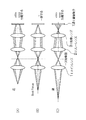
- FIG. 11 (A) to 11 (C) are diagrams showing separation states of images formed on the image sensor due to differences in the front pin, focus (best focus), and rear pin, respectively.
- the mirror 4 shown in FIG. 10 is omitted in order to compare the difference in separation due to focus.
- the focused image of the pupil-divided images is formed (matched) at the same position on the image sensor, but FIG. 11A and ( As shown in part C), the images serving as the front pin and the rear pin are formed (separated) at different positions on the image sensor.
- the electronic camera includes an imaging unit, a light amount distribution detection unit, an image shift amount detection unit, and an image processing unit.
- the imaging unit photoelectrically converts a subject image by the photographing optical system to generate photographed image data.
- the light quantity distribution detection unit detects the light quantity distribution by the light flux from the subject passing through different optical paths.
- the image shift amount detection unit detects image shift amounts at a plurality of locations in the photographing screen based on the light amount distribution.
- the image processing unit generates stereogram image data by changing the positional relationship of the subject in the captured image data in the horizontal direction based on the image shift amounts at a plurality of locations.
- the stereogram image data is corrected by changing the positional relationship of the subject in the stereogram image data in the horizontal direction. Since the stereogram image data can be corrected, it is possible to obtain a natural stereogram image with less discomfort for the user.
- Patent Document 2 pattern matching is performed on the left-eye image and the right-eye image captured by the left and right cameras with respect to the stereo image of either the left-eye image or the right-eye image as a reference. Then, a matching image for each pixel is specified, an intermediate position image is obtained by interpolating the inter-pixel distance between the matching images for the left and right pixels, and the right is obtained by extrapolating the inter-pixel distance between the matching images for the left and right pixels.
- a multi-view image creation method for obtaining an outside image and a left outside image is disclosed.
- a stereo matching processing unit (object detection means) is processed by an image processing unit, and the two image data A and B stored in the memory unit are set by the above-described space setting unit. One or more corresponding points (objects) corresponding to each other are detected with respect to the space.
- the distance calculation unit calculates the three-dimensional coordinate value (position information) of the corresponding point detected by the stereo matching processing unit described above.
- the configuration of the photographing lens of the photographing unit and the photographing unit is different, and the photographing lens includes a zoom lens and a zoom lens driving unit (drive means) (not shown) that drives the zoom lens, and the photographing lens has a wide angle of the zoom lens of the photographing lens. A fixed focus lens having an angle of view equal to the end is provided. With such a configuration, the cost is reduced.
- Patent Documents 4 to 6 are examples of a three-dimensional image generation technique using a single optical system.
- a large number of pixels are arranged on the same imaging surface, and in a solid-state imaging device that generates an image signal by photoelectrically converting a subject image formed on the imaging surface, Disclosed is a solid-state imaging device that is divided into groups and has different light-receiving incidence angles of pixels in each group.
- Patent Documents 7 to 11 are examples of a method for searching corresponding points between different viewpoint images, a technique for acquiring depth information by stereo matching, and a three-dimensional image generation technique using two-dimensional images and distance information (depth information). .
- Patent Document 12 in order to focus only on the main subject and intentionally blur other parts other than the main subject, the focus position is discretely moved by a predetermined amount of movement, and images are sequentially captured.
- a blur-enhanced image can be obtained by obtaining a plurality of images and combining the plurality of images.
- Patent Document 13 divides an image to be photographed into a plurality of areas, and an area that is a foreground or background of a main subject is imaged with a shift from a focal position corresponding to the distance of the area. Then, an image of each area is individually extracted from the captured images of each captured area, and these are combined to create one image. As a result, it is possible to easily take an image with a desired amount of blur.
- Patent Document 14 shows an example of a parallax map creation method.
- the parallax value is adjusted by converting the parallax value of the parallax value distribution image linearly or non-linearly, and the design condition of the stereoscopic image, that is, “the maximum with the maximum pop-out amount and the maximum subtraction amount”
- the design condition of the stereoscopic image that is, “the maximum with the maximum pop-out amount and the maximum subtraction amount”
- a multi-view three-dimensional image that satisfies the requirements of “effectively taking a viewpoint while keeping within the parallax range” and “make the parallax of the main subject position in the image as zero as possible” at the same time, and effectively using the maximum parallax value range. Change to depth value configuration.
- a virtual viewpoint image at each viewpoint position is generated using the corrected disparity value distribution image and the viewpoint position, that is, the ratio r of each image to the parallax of the input left and right stereo image pair corresponding to the viewpoint position, and all pixels are valid.
- a new viewpoint image is generated. This process is repeated for the number of viewpoints to obtain a multi-viewpoint image sequence.
- a three-dimensional stripe image is synthesized from the multi-viewpoint image sequence. At this time, a three-dimensional image is synthesized so that pixels at the same coordinates of each image in the multi-view image sequence are arranged as adjacent pixels according to the viewpoint arrangement of the image.
- the images of the respective viewpoints are decomposed into strips for each line in the vertical direction, and are synthesized by the number of viewpoints in the reverse order of the viewpoint positions.
- the reason why the viewpoints are arranged in the reverse order is that when observing with the lenticular plate, the image is observed in the left and right direction within one pitch of the lenticular. When a lenticular plate is superimposed on an image printed by this process, a good stereoscopic image can be observed.
- the 3D image output apparatus selects a parallax adjustment parameter according to the screen size or viewing distance of the 3D display, converts the parallax amount at each feature point using the selected conversion table, and converts the parallax amount to the converted parallax amount.
- a corresponding parallax image is generated, and a plurality of parallax images including the generated parallax image are output to the display device.
- the viewing distance is automatically acquired by a distance measuring means disposed at or near the 3D display or manually input.
- the 3D image output apparatus outputs a parallax image to a stereoscopic display device having various screen sizes, a printer that generates a stereoscopic display print, and the like.
- JP 2007-104248 A JP 2009-124308 A JP 2008-92007 paragraphs 0047-0048, 0071 JP2003-7994 Japanese Patent Laid-Open No. 2001-12916 JP 2001-016611 Japanese Unexamined Patent Publication No. 08-331607 JP 2008-141666 A JP 2009-14445 JP 2008-116309 Japanese Unexamined Patent Publication No. 2000-102040 JP 2008-271241 A JP 2003-209727 A JP 2010-226500 A Japanese Patent Laid-Open No. 2003-209858 JP 2010-206774 A
- the pupil division type stereoscopic imaging device that captures a parallax image and selectively generates a stereoscopic image by selectively acquiring image information that has passed through different pupil positions of the image imaging means, such as Patent Documents 4 to 6,
- the parallax at the in-focus position becomes 0, and the parallax corresponding to the blur (defocus amount) occurs at the non-in-focus position.
- the present invention provides a pupil-dividing stereoscopic imaging device capable of simultaneously obtaining a planar image and a stereoscopic image in which a desired portion such as the foreground and background is blurred with respect to a main subject, and the planar image in the pupil-dividing stereoscopic imaging device.
- a method for simultaneously capturing a stereoscopic image is provided.
- a discrete image is formed between a first pixel that photoelectrically converts an object image formed by a photographing lens by a photoelectric conversion element group and outputs a first image signal, and the first pixel. And a second image signal that outputs a second image signal having a phase difference by photoelectrically converting a plurality of subject images from the divided pupil region by a photoelectric conversion element group.
- An imaging unit having a pixel, an imaging control unit that controls the imaging unit to capture the first image signal and the second image signal at the same time, and a second image signal output from the imaging unit
- the parallax information calculation unit that calculates parallax information
- the planar image creation unit that creates a planar image based on the first image signal output from the imaging unit
- the parallax information calculation unit Decide the target pixel to be blurred.
- an imaging device comprising: a blurring processing unit, the performing blurring processing on the target pixel of the image.
- the second aspect of the present invention includes a recording unit that records the first image signal and the parallax information in association with each other, and the blurring processing unit has a plane according to the parallax information recorded by the recording unit in association with the first image signal.
- an imaging apparatus that determines a target pixel to be subjected to image blurring processing and performs blurring processing on the target pixel of a planar image.
- the disparity information includes a disparity map that represents the amount of disparity between corresponding points of the set of viewpoint images
- the blurring processing unit has a corresponding point where the amount of disparity between the corresponding points is equal to or greater than a predetermined value. Is provided as a target pixel to be subjected to the blurring process, and an imaging apparatus for performing the blurring process on the target pixel is provided.
- a contour information extraction unit that extracts at least contour information from the first image signal
- the blur processing unit is a target on which blur processing is performed based on the contour information extracted by the contour information extraction unit.
- An imaging apparatus that determines a pixel and applies a blurring process to a target pixel is provided.
- the disparity information includes distance information of each pixel
- the blurring processing unit has a second pixel in which the distance information is farther than the predetermined first distance and / or the distance information is the predetermined second.
- An imaging device is provided that determines pixels in the foreground that are smaller than the distance of the target pixel as target pixels to be subjected to the blur processing of the planar image, and performs the blur processing on the target pixels.
- an imaging device in which a blur processing unit determines a pixel constituting an area designated by a user operation as a target pixel to be subjected to a blur processing of a planar image, and performs the blur processing on the target pixel.
- the disparity information includes a disparity map that represents the amount of disparity between corresponding points of the set of viewpoint images, and the blurring processing unit performs each blurring process according to the amount of disparity between corresponding points.
- an imaging device applied to pixels constituting corresponding points.
- an imaging apparatus in which a blur processing unit performs blur processing of a degree specified by a user operation on a target pixel.
- the ninth aspect of the present invention provides an imaging apparatus in which phase difference pixels are arranged at predetermined intervals in a pixel group corresponding to one or a plurality of color filters in a predetermined arrangement.
- the tenth aspect of the present invention provides an imaging apparatus in which phase difference pixels are arranged at predetermined intervals in a pixel group corresponding to a Bayer-arranged green, red, or blue color filter.
- a diaphragm unit capable of adjusting a light amount of a light beam formed on the photoelectric conversion element group of the imaging unit, and a diaphragm unit so as to obtain a phase difference between the second image signal output from the imaging unit.
- an aperture control unit that controls the opening amount of the image pickup apparatus.
- a discrete image is formed between a first pixel that photoelectrically converts an object image formed by a photographing lens by a photoelectric conversion element group and outputs a first image signal, and the first pixel. And a second image signal that outputs a second image signal having a phase difference by photoelectrically converting a plurality of subject images from the divided pupil region by a photoelectric conversion element group.
- An image capturing apparatus including an image capturing unit having a plurality of pixels controls the image capturing unit to capture the first image signal and the second image signal simultaneously; and the second image signal output from the image capturing unit A step of calculating parallax information based on the step, a step of creating a flat image based on the first image signal output from the imaging unit, and a target pixel on which the blurring process of the flat image is to be performed according to the calculated parallax information.
- Target of flat image To provide an imaging method for performing the steps of applying a blurring process on the element, the.
- a planar image is generated from the first image signal out of the simultaneously output first image signal and second image signal, and parallax information is calculated based on the second image signal. Is done. Then, in accordance with the calculated parallax information, a target pixel to be subjected to the blurring process of the planar image is determined, and the blurring process is performed on the target pixel of the planar image.
- the pupil-division imaging device it is possible to blur the appropriate position according to the parallax information indicating the perspective of the subject and the magnitude of the parallax amount.
- a stereoscopic image having a parallax and a planar image can be obtained simultaneously by one shooting.
- Block diagram of a camera according to the first embodiment The figure which shows the structural example of the pupil division
- the figure which showed 1 pixel of 1st, 2nd pixel each 3 is an enlarged view of the main part.
- Flowchart of 2D / 3D simultaneous imaging processing The figure which shows the structural example of the pupil division parallax image acquisition image pick-up element CCD (G * pixel) which concerns on 2nd Embodiment.
- the figure which shows an example of the conventional monocular three-dimensional imaging device The figure which shows the separation state of the image imaged on an image sensor
- FIG. 1 is a block diagram showing an embodiment of a camera 1 according to the first embodiment.
- the camera 1 records the captured image on the memory card 54, and the operation of the entire apparatus is centrally controlled by a central processing unit (CPU) 40.
- CPU central processing unit
- the camera 1 is provided with an operation unit 38 such as a shutter button, a mode dial, a playback button, a MENU / OK key, a cross key, and a BACK key.
- a signal from the operation unit 38 is input to the CPU 40, and the CPU 40 controls each circuit of the camera 1 based on the input signal. For example, lens drive control, aperture drive control, shooting operation control, image processing control, image data control, Recording / reproduction control, display control of a liquid crystal monitor (LCD) 30 for stereoscopic display, and the like are performed.
- LCD liquid crystal monitor
- the ROM 10 stores programs executed by the CPU 40 and various data necessary for control, pixel defect information of the CCD 16, various constants / information relating to camera operation, and the like.
- the shutter button is an operation button for inputting an instruction to start shooting, and is configured by a two-stroke switch having an S1 switch that is turned on when half-pressed and an S2 switch that is turned on when fully pressed.
- the mode dial is a selection means for selecting one of an auto shooting mode for shooting a still image, a manual shooting mode, a scene position such as a person, a landscape, a night view, and a moving image mode for shooting a moving image.
- the playback button is a button for switching to a playback mode in which a still image or a moving image of a stereoscopic image (3D image) or a planar image (2D image) that has been captured and recorded is displayed on the LCD 30.
- the MENU / OK key is an operation key having both a function as a menu button for instructing to display a menu on the screen of the LCD 30 and a function as an OK button for instructing confirmation and execution of selection contents.
- the cross key is an operation unit for inputting instructions in four directions, up, down, left, and right, and functions as a button (cursor moving operation means) for selecting an item from the menu screen or instructing selection of various setting items from each menu. To do.
- the up / down key of the cross key functions as a zoom switch for shooting or a playback zoom switch in playback mode
- the left / right key functions as a frame advance (forward / reverse feed) button in playback mode.
- the BACK key is used to delete a desired object such as a selection item, cancel an instruction content, or return to the previous operation state.
- the image light indicating the subject is a solid-state image sensor (hereinafter referred to as “CCD”, which is a phase difference image sensor capable of acquiring a pupil-divided parallax image via the imaging lens 12 and the diaphragm 14, but may be a CMOS or the like.
- CCD solid-state image sensor
- the image is formed on 16 light receiving surfaces.
- the imaging lens 12 is driven by a lens driving unit 36 controlled by the CPU 40, and focus control, zoom (focal length) control, and the like are performed.
- the diaphragm 14 is composed of, for example, five diaphragm blades, and is driven by a diaphragm drive unit 34 controlled by the CPU 40.
- the diaphragm value (F value) F2.8 to F11 is controlled in five steps in increments of 1AV.
- the CPU 40 controls the diaphragm 14 via the diaphragm driving unit 34, and performs charge accumulation time (shutter speed) in the CCD 16, image signal readout control from the CCD 16, and the like via the CCD control unit 32.
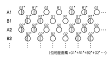
- FIG. 2 is a diagram illustrating a configuration example of the CCD 16.
- the CCD 16 has a pixel of line A composed of odd lines A1, A2,... And a pixel of line B composed of even lines B1, B2,.
- the image signals for the two surfaces photoelectrically converted by the pixels of these two lines A and B can be read out independently.
- the plurality of light receiving elements corresponding to each pixel group form an effective pixel region for obtaining an effective imaging signal and an optical black region (hereinafter referred to as “OB region”) for obtaining a black level reference signal.
- the OB region is actually formed so as to surround the effective pixel region.
- the odd-numbered line A of the CCD 16 has a GRGR... Pixel array line among pixels having R (red), G (green), and B (blue) color filters. And lines of the pixel array of BGBG... Are alternately provided.
- the color filter color arrangement of the odd-numbered line A as a whole is a so-called Bayer arrangement in which “G” and “B” are repeated in one direction and “G” and “R” are repeated in a direction orthogonal thereto.
- phase difference pixels G * and R * are provided every four pixels.
- phase difference pixels G1 * and R1 * are provided in a line of the pixel array of G1R1G1R1.
- phase difference pixel is provided every four pixels in a line of the pixel array of BGBG.
- the phase difference pixel B * 2 is provided in the line of the pixel array of B2G2B2G2.
- phase difference pixels G * , R * , and B * a pixel light-shielding portion is formed, and when the camera 1 is placed horizontally, the light shielding member shields the right half of the light-receiving surface of the photodiode PD of the pixel.
- the pixels of the even lines B of the CCD 16 are alternately provided with the GRGR... Pixel array lines and the BGBG.
- the pixels of the odd line A are shifted to the right in the line direction by a half pitch.
- the color filter color arrangement of the even line B as a whole is a so-called Bayer arrangement.
- the arrangement of the color filters of the CCD 16 is a color arrangement in which two Bayer arrangements are combined as a whole, and is also referred to as a double Bayer arrangement.
- phase difference pixels G * and R * are provided every four pixels.
- phase difference pixels G1 * and R1 * are provided in a line of the pixel array of G1R1G1R1.
- Phase difference pixels B * are provided every four pixels.
- the phase difference pixel B2 * is provided in the line of the pixel array of B2G2B2G2.
- phase difference pixels G * , R * , and B * a pixel light-shielding portion is formed, and when the camera 1 is placed horizontally, the light shielding member shields the left half of the light-receiving surface of the photodiode PD of the pixel.
- the imaging lens 12 that focuses the subject image on the CCD 16 is in focus, the image signal from the phase difference pixels G * , R * , B * of the odd line A and the phase difference pixel G of the even line B
- the image signals from * , R * , and B * match. If the focusing point is in front of or behind the light receiving surface of the CCD 16, a phase difference is generated between these image signals. Then, the phase shift direction is reversed between the case where the image formation point is before and the case where the image formation point is after.
- FIG. 3 is a diagram showing the imaging lens 12, the diaphragm 14, and the phase difference pixels of the CCD 16 in FIG. 2 (A), and FIG. 4 is an enlarged view of the main part of FIG.
- the light beam passing through the exit pupil enters the normal CCD pixel (photodiode PD) through the microlens L without being restricted.
- a light shielding member 16A is formed in the phase difference pixel of the CCD 16.
- the right half or the left half of the light receiving surface of the phase difference pixel (photodiode PD) is shielded by the light shielding member 16A.
- the upper half or the lower half of the light receiving surface of the phase difference pixel (photodiode PD) is shielded by the light shielding member 16A.
- the opening 16B of the light shielding member 16A is located at a position displaced by a predetermined amount ⁇ from the optical axis Ic of the micro lens L to the right, left, upper, or lower direction (for example, leftward from the optical axis in the part of FIG. 4B). Is provided.
- the light beam passes through the opening 16B and reaches the light receiving surface of the photodiode PD. That is, the light shielding member 16A functions as a pupil division member.
- the odd-numbered-phase phase difference pixels and the even-numbered-phase phase difference pixels have different regions (right half / left half or upper half / lower half) where the luminous flux is restricted by the light shielding member 16A.
- the even-numbered phase difference pixel limits the left half of the luminous flux
- the odd-numbered phase retardation pixel limits the right half of the luminous flux
- the upper half of the luminous flux is limited in the even-line phase difference pixels
- the lower half of the luminous flux is restricted in the odd-line phase difference pixels.
- the above viewpoint image is obtained from the phase difference pixel.
- the outputs of the first pixel (left viewpoint pixel) and the second pixel (right viewpoint pixel) are out of phase or out of phase depending on the state of the rear pin, the focus, and the front pin. Match. Since the phase difference between the output signals of the odd-numbered and even-numbered phase difference pixels corresponds to the defocus amount of the imaging lens 12, AF control of the imaging lens 12 can be performed by detecting this phase difference (phase difference AF). ).
- the signal charge accumulated in the CCD 16 is read out as a voltage signal corresponding to the signal charge based on the readout signal applied from the CCD control unit 32.
- the voltage signal read from the CCD 16 is applied to the analog signal processing unit 18 where the R, G, and B signals for each pixel are sampled and held, amplified, and then applied to the A / D converter 20.
- the A / D converter 20 converts R, G, and B signals that are sequentially input into digital R, G, and B signals and outputs them to the image input controller 22.
- the digital signal processing unit 24 performs predetermined processing such as offset control, gain control processing including white balance correction and sensitivity correction, gamma correction processing, YC processing, etc., on the digital image signal input via the image input controller 22. Perform signal processing.
- predetermined processing such as offset control, gain control processing including white balance correction and sensitivity correction, gamma correction processing, YC processing, etc.
- the image data read from the phase difference pixels of the odd lines of the CCD 16 is processed as left viewpoint image data and read from the phase difference pixels of the even lines.
- the processed image data is processed as right viewpoint image data.
- the left viewpoint image data and right viewpoint image data (3D image data) processed by the digital signal processing unit 24 are input to the VRAM 50.
- the VRAM 50 includes an A area and a B area each storing 3D image data representing a 3D image for one frame.
- 3D image data representing a 3D image for one frame is rewritten alternately in the A area and the B area.
- the written 3D image data is read from an area other than the area in which the 3D image data is rewritten in the A area and the B area of the VRAM 50.
- the 3D image data read from the VRAM 50 is encoded by the video encoder 28 and output to a stereoscopic display liquid crystal monitor (LCD) 30 provided on the back of the camera, whereby a 3D subject image is displayed on the display screen of the LCD 30. Displayed above.
- LCD liquid crystal monitor
- the LCD 30 is a stereoscopic display means capable of displaying stereoscopic images (left viewpoint image and right viewpoint image) as directional images having predetermined directivities by a parallax barrier.
- the 3D display method of the LCD 30 is not limited to this, and the left viewpoint image and the right viewpoint image can be individually viewed by using a lenticular lens or special glasses such as polarized glasses or liquid crystal shutter glasses. It may be a thing.
- the CPU 40 starts the AF operation and the AE operation, and the focus lens in the imaging lens 12 is aligned via the lens driving unit 36. Control to come to the focal position.
- the image data output from the A / D converter 20 when the shutter button is half-pressed is taken into the AE detection unit 44.
- the AE detection unit 44 integrates the G signals of the entire screen or integrates the G signals that are weighted differently in the central portion and the peripheral portion of the screen, and outputs the integrated value to the CPU 40.
- the CPU 40 calculates the brightness of the subject (shooting Ev value) from the integrated value input from the AE detection unit 44, and the aperture value of the diaphragm 14 and the electronic shutter (shutter) of the CCD 16 that can obtain appropriate exposure based on this shooting Ev value. (Speed) is determined according to a predetermined program diagram, the aperture 14 is controlled via the aperture drive unit 34 based on the determined aperture value (planar image aperture control), and CCD control is performed based on the determined shutter speed. The charge accumulation time in the CCD 16 is controlled via the unit 32. Note that the brightness of the subject may be calculated based on an external photometric sensor.
- the predetermined program diagram corresponds to the brightness of the subject (shooting EV value), and is a combination of the aperture value of the diaphragm 14 and the shutter speed of the CCD 16 or a combination of these and the shooting sensitivity (ISO sensitivity). )
- the conditions are designed.
- the F value of the aperture is increased, the parallax becomes weaker, and if the F value is fixed at a constant small value, the parallax becomes stronger.
- FIG. On the other hand, if the F value is fixed at a constant large value, it is possible to capture an image that is in focus throughout the entire image. In this embodiment, in order to obtain a pair of images having parallax and simultaneously obtain a planar image, the F value is fixed at a constant small value (a parallax priority program diagram).
- the F value is fixed at a constant small value.
- the AF processing unit 42 is a part that performs contrast AF processing or phase difference AF processing.
- contrast AF processing high-frequency components of image data within a predetermined focus area (such as a rectangular area in the center of the screen) of at least one of left viewpoint image data and right viewpoint image data are extracted.
- the AF evaluation value indicating the in-focus state is calculated by integrating the high frequency component.
- the AF control is performed by controlling the focus lens in the imaging lens 12 so that the AF evaluation value is maximized.
- the phase difference between the phase difference pixels in the predetermined focus area of the left viewpoint image data and the right viewpoint image data is detected, and based on the information indicating the phase difference. Find the defocus amount.
- AF control is performed by controlling the focus lens in the imaging lens 12 so that the defocus amount becomes zero.
- the two pieces of image data temporarily stored in the memory 48 are appropriately read out by the digital signal processing unit 24, and a predetermined signal including generation processing (YC processing) of luminance data and color difference data of the image data is performed here. Processing is performed.
- the YC processed image data (YC data) is stored in the memory 48 again. Subsequently, the two pieces of YC data are respectively output to the compression / decompression processing unit 26 and subjected to predetermined compression processing such as JPEG (joint photographic experts group), and then stored in the memory 48 again.
- predetermined compression processing such as JPEG (joint photographic experts group
- a multi-picture file (MP file: a file in a format in which a plurality of images are connected) is generated from two pieces of YC data (compressed data) stored in the memory 48, and the MP file is generated by the media controller 52. It is read and recorded in the memory card 54.
- MP file a file in a format in which a plurality of images are connected
- the defocus map creation unit 61 calculates the phase difference between the corresponding phase difference pixels between the odd lines and the even lines.
- the defocus map creation unit 61 obtains a defocus amount based on the phase difference calculated for each of the phase difference pixels.
- a set of defocus amounts corresponding to each of the corresponding phase difference pixels is referred to as a defocus map.
- the defocus map creation unit 61 has a volatile storage medium such as a RAM, and temporarily stores the obtained defocus map.
- the defocus map creation unit 61 may detect corresponding points between the respective phase difference pixels in the stereo matching processing unit 83 and create a defocus map based on a difference in position information between the corresponding points.
- the defocus map creation unit 61 also applies to the non-phase difference pixels that are pixels from which the corresponding points are not originally obtained and the pixels from which the corresponding points are not obtained from the defocus amounts obtained between the phase difference pixels. Find the defocus amount. That is, a dense defocus map can be obtained by performing the interpolation process using the defocus amount of the phase difference pixel in the vicinity of the non-phase difference pixel. Pixels used for interpolation of the defocus amount of a certain non-phase difference pixel are neighboring pixels of the same color.
- the restoration filter storage unit 62 is configured by a nonvolatile storage medium such as a ROM, and the image height (distance from the image center, typically the optical axis center L of the imaging lens 12) of each small region in each viewpoint image. And a restoration filter corresponding to the defocus amount (or subject distance).
- the restoration unit 63 deconvolves the small area with the restoration filter selected for each small area of each viewpoint image, and restores the corresponding small area of the viewpoint image.
- the blur of the optical system in particular, the blur of the image corresponding to the peripheral pixels on the light receiving surface in which the unbalanced incidence of the light flux occurs is removed.
- the stereo matching processing unit (object detection means) 83 detects one or more corresponding points (objects) corresponding to each other between the two image data A and B stored in the memory 48 at the same timing.
- a processing method in the stereo matching processing unit 83 a known technique using a region-based method, a segment-based method, an isoluminance line method, or the like can be used. Further, the stereo matching may be passive or active. In addition, stereo matching between images having different numbers of pixels can be performed based on known techniques such as Patent Documents 3 and 7 to 11.
- the distance calculation unit 84 calculates the three-dimensional coordinate value (distance information) of the corresponding point detected by the stereo matching processing unit 83 described above.
- a calculation method of the distance information in the distance calculation unit 84 a known technique for calculation based on the principle of triangulation can be used.
- the stereo matching processing unit 83 and the distance calculation unit 84 may be configured by a program, or may be configured by an IC, an LSI, or the like.
- a disparity map (a reference viewpoint image, for example, the image data A to another viewpoint image, for example, a disparity amount from a corresponding point to the image data B, representing another viewpoint image) is a distance information or a defocus map.
- the following distance information and defocus map processing can also be performed for a parallax map.
- the distance information to the subject, the defocus map, or the parallax map is comprehensively referred to as parallax information.
- the calculation of the parallax information can be performed not by the camera 1 but by another information processing apparatus such as a personal computer and its control program.
- the acquisition pixel of the first image data and the acquisition pixel of the second image data may or may not have the same configuration.
- the first image data has color information and luminance information, but the second image data may have only luminance information.
- the second pixel may be a monochrome CCD that can receive an infrared region, and active stereo matching using infrared light as in Patent Document 7 may be employed.
- both the first image data and the second image data include at least luminance information.
- both the first image data and the second image data include color information.
- both the first image data and the second image data include luminance information and color information.
- the 3D image processing unit 85 can generate a 3D image from a set of viewpoint images acquired from the CCD 16. This is the same as in Patent Document 2. Note that three-dimensional image generation from parallax information can be performed based on known techniques such as Patent Documents 7 to 11. The three-dimensional image is generated when the shooting mode is set to “3D still image recording”, and a three-dimensional image having a desired amount of parallax is displayed on the LCD 30.
- the parallax amount of the 3D image generated by the 3D image processing unit 45 may be a fixed value or an arbitrary set value.
- the blur processing unit 86 performs low-pass filter processing to remove image signal components having a predetermined frequency or higher.
- FIG. 5 shows a flowchart of 2D / 3D simultaneous imaging processing according to the first preferred embodiment of the present invention. This process is started in response to the shooting mode being set to “2D / 3D simultaneous recording”. This process is defined in a program executed by the CPU 40, and the program is stored in a memory (ROM) 48 or the like.
- ROM memory
- the CPU 40 determines whether or not the shutter button of the operation unit 38 has been pressed (half-pressed) in the first stage. In the case of Yes, it progresses to S2, and in the case of No, the said determination is repeated. Meanwhile, the image acquired from the CCD 16 can be displayed on the LCD 30 as a 2D or 3D through image. Whether the 2D or 3D through image is displayed may be arbitrarily selected by the operation unit 38.
- the CPU 40 determines the aperture value X and the shutter speed according to the parallax priority program diagram in response to the shooting mode being set to “2D / 3D simultaneous recording”.
- the CPU 40 determines whether or not the shutter button of the operation unit 38 has been pressed in the second stage (full press). If Yes, the process proceeds to S4. If No, the determination is repeated. Meanwhile, the image acquired from the CCD 16 can be displayed on the LCD 30 as a 2D or 3D through image.
- the CPU 40 controls the aperture 14 via the aperture drive unit 34 based on the aperture value X determined in S2 (parallax priority aperture control), and via the CCD control unit 32 based on the determined shutter speed.
- the charge accumulation time in the CCD 16 is controlled.
- left and right image data A and B (a set of viewpoint images) having parallax for the parallax pixel R * G * B * and no parallax for the other pixels are acquired from the CCD 16.
- the CPU 40 stores the left and right image data A and B in the VRAM 50 as 3D image data.
- the CPU 40 adds the image signal for each of the two pixels corresponding to the same luminous flux divided in the pupil for the left and right image data A and B. Thereby, a high-resolution 2D image is generated.
- the CPU 40 stores the added image signal in the VRAM 50 as 2D image data.
- the 2D image data may be one of those displayed as a 2D postview image on the LCD 30 or may be different from the 2D postview image.
- the CPU 40 causes the stereo matching processing unit 83 and the distance calculation unit 84 to calculate stereo matching and distance information (parallax information).
- the stereo matching processing unit 83 performs stereo matching based on the 3D image data A and B acquired in S3.
- the distance calculation unit 84 calculates distance information for each corresponding point detected by the stereo matching processing unit 83. Subsequently, for the points (pixels) for which the corresponding points between the image data A and B are not originally obtained from the distance information calculated in this way, and for the uncorresponding points (pixels) for which no corresponding points have been obtained. Also seek distance information. This can be realized by interpolation processing using already calculated disparity information in the same manner as in Patent Document 15. Thereby, a dense distribution of parallax information corresponding to each pixel of the 2D image data is obtained.
- the blurring processing unit 86 determines the blurring target pixel of the 2D image data based on the distance information (parallax information) for each pixel calculated in S5. Details of the blur target pixel determination will be described later.
- the restoration unit 63 adjusts the parallax (defocus amount) to 0 for each pixel of the 2D image data other than the blurring target pixel.
- the method of adjusting the parallax can be performed by a known technique such as Patent Document 2 and Patent Document 15. Thereby, the blur between corresponding pixels of pixels other than the blurring target pixel is restored.
- the blurring processing unit 86 performs a blurring process on the determined target pixel for the blurring process. Details of the blurring process will be described later.
- the CPU 40 compresses and records the 2D image data after the processing in S7 on the memory card 54.
- the CPU 40 can also compress and record 3D image data and parallax information in the memory card 54 together with the 2D image data or independently of the 2D image data.
- the information processing apparatus such as the camera 1 or the personal computer reads the 2D image data and the parallax information from the memory card 54, and associates them with the read 2D image data. Based on the obtained parallax information, the same blurring process as the blurring processing unit 86 described below can be performed.
- the video encoder 28 can display a 3D image in which the parallax is adjusted to a desired range (strong, normal, or weak) from the 3D image data and the parallax information on the LCD 30.
- the parallax adjustment according to the visual condition is as in the known art. For example, as in Patent Document 16, the parallax is adjusted based on the horizontal width size and viewing distance of the LCD 30.
- the determination of the pixel to be blurred in S6 is automatically performed. However, in addition to this, it may be determined based on a user operation. For example, the following pixels are determined as the target of the blurring process.
- the blur processing unit 86 refers to the distance information of each pixel, and a distant view pixel (for example, a subject image pixel of 5 m or more) farther than a predetermined first distance or a predetermined second distance.
- a small foreground pixel (for example, a subject image pixel of 50 cm or less) is determined as a blur target pixel.
- the blurring processing unit 86 refers to the parallax map of each pixel, and determines a pixel that constitutes a corresponding point where the amount of parallax between corresponding points is equal to or greater than a predetermined value (for example, two pixels) as a blurring target pixel. To do.
- a predetermined value for example, two pixels
- Example 3 In addition to Example 1 and / or Example 2, the blurring processing unit 86 extracts contour information (high-frequency component of an image signal) from 2D image data, and defines pixels constituting a background region that is outside the contour component. The pixel to be blurred is determined. In addition, when the edge component of the subject exists in the vicinity of the phase difference pixel, there is a possibility that the contour information is not accurately extracted. Therefore, it is desirable that the phase difference pixels are arranged discretely.
- contour information high-frequency component of an image signal
- Example 4 In addition to Example 1, Example 2 and / or Example 3, the blurring processing unit 86 determines each pixel included in the region designated by the user operation as a blurring target pixel.
- the degree of the blurring process in S7 may be determined based on a user operation or may be automatically determined.
- the blur processing unit 86 sets the parallax amount between corresponding points of the blur target pixel to ⁇ , and when the blur is specified, sets the parallax amount to ⁇ , When the blur weakness is designated, the parallax amount is set to ⁇ .
- the blur processing unit 86 may change the degree of blur according to the amount of parallax indicated by the parallax map. That is, if the amount of parallax between certain corresponding points is large, the degree of blurring of those corresponding points is increased with a low-pass filter or the like accordingly.
- the camera 1 captures a set of viewpoint images by aperture control with parallax priority, obtains parallax information from the set of viewpoint images, and performs a blurring process on the 2D image based on the parallax information. A part is determined, and a blurring process is performed on the part.
- the pupil-division imaging device it is possible to simultaneously obtain a planar image and a parallax image in which an appropriate position is blurred according to the parallax information indicating the perspective of the subject and the magnitude of the parallax amount.
- shooting since shooting is performed on the open side, it is possible to capture images even in dark scenes and high shooting sensitivity.
- the arrangement of the phase difference pixels is not limited to that shown in FIG. 2, and various types can be adopted.
- the first pair A1 and B1 of the odd-numbered and even-numbered lines are set as phase difference pixels every four pixels, and the next pair of G pixels of the lines A2 and B2 are not set as phase difference pixels.
- the pixels are phase difference pixels every four pixels. This is repeated in the same manner, and every other phase difference pixel G is arranged for each pair of lines AB.
- the pixels used for the interpolation of the defocus amount of the G pixel which is the non-phase difference G pixel are the phase difference G pixels of the same color in the vicinity.
- the pixel used for interpolation of the defocus amount of the BG pixel of the non-phase difference pixel is the neighboring phase difference pixel G.
- a phase difference pixel is arranged for every four pixels for all the R, G, and B pixels in the odd and even lines.
- the distribution range of the phase difference pixels may be local, such as the area near the center of the screen or the area other than the periphery of the screen, instead of the entire effective pixels.
- the number of pitches between the phase difference pixels is not limited to 4 pixels, and may be more or less.
- the number of pitches between the phase difference pixels is 4, the normal pixel RGB exists between the phase difference pixels, and the image signal of the phase difference pixel can be interpolated by the surrounding normal pixels, so the pitch of 4 pixels is optimal. It is.
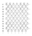
- phase difference pixels may be arranged at a pitch of 4 pixels in both the vertical direction and the horizontal direction.
- the lines A3, B3, A4, and B4 have a normal pixel arrangement, and the lines A5, B5, A6, and B6 that are vertically separated from the lines A1, B1, A2, and B2 by the line A1, B5, A6, and B6 are the lines A1 in FIG. , B1, A2, and B2, phase difference pixels G * , R * , and B * are arranged at a distance of 4 pixels in the horizontal direction.
- the phase difference pixels of the horizontal lines in FIGS. 6 and 7 may be arranged for each line separated by 4 pixels in the vertical direction.
- phase difference for each color can be accurately detected. Further, if the number of pitches between the phase difference pixels is increased, the phase difference interpolation processing is reduced accordingly, and the phase difference between corresponding points can be accurately detected.
- phase difference pixels since the increase in the phase difference pixels may affect the image quality of the 2D image, it is desirable to determine the arrangement of the phase difference pixels in consideration of both the image quality of the 2D / 3D image.
- the CCD 16 having the above configuration is configured such that the regions (right half and left half) in which the light flux is restricted by the light shielding member 16A are different in the phase difference pixels of the odd and even lines.
- the microlens L and the photodiode PD may be shifted relative to each other in the left-right direction, and the light flux incident on the photodiode PD may be limited by the shifting direction.
- the light beam incident on each pixel may be limited (for example, FIG. 9), or the pupil is divided by a mirror ( For example, FIG.
Landscapes
- Engineering & Computer Science (AREA)
- Physics & Mathematics (AREA)
- Multimedia (AREA)
- Signal Processing (AREA)
- General Physics & Mathematics (AREA)
- Optics & Photonics (AREA)
- Computer Vision & Pattern Recognition (AREA)
- Testing, Inspecting, Measuring Of Stereoscopic Televisions And Televisions (AREA)
- Studio Devices (AREA)
- Stereoscopic And Panoramic Photography (AREA)
Abstract
L'invention concerne une caméra (1) munie d'un circuit à couplage de charge CCD (16) dans lequel des pixels à différence de phase (G*, R*, B*) sont agencés de façon discrète pour saisir des images à partir d'un ensemble d'images de point de vue. L'invention fait intervenir des opérations consistant à piloter l'ouverture du diaphragme en conjonction avec une priorité de disparité, à obtenir des informations de disparité à partir de l'ensemble d'images de point de vue, à déterminer une portion de l'image en 2D sur laquelle des retouches sont envisagées sur la base des informations de disparité, et à appliquer les retouches à la portion en question. Par conséquent, dans un dispositif de saisie d'images de type à division subalterne, il est possible d'obtenir simultanément à la fois une image plane retouchée par aérographe au niveau d'une position appropriée, et une image de disparité en fonction des informations de disparité avec indication de la perspective de l'objet, de l'importance du degré de disparité, etc.
Priority Applications (3)
| Application Number | Priority Date | Filing Date | Title |
|---|---|---|---|
| CN201280016911.2A CN103493484B (zh) | 2011-03-31 | 2012-03-07 | 成像装置和成像方法 |
| JP2013507321A JP5640143B2 (ja) | 2011-03-31 | 2012-03-07 | 撮像装置及び撮像方法 |
| US14/039,700 US8885026B2 (en) | 2011-03-31 | 2013-09-27 | Imaging device and imaging method |
Applications Claiming Priority (2)
| Application Number | Priority Date | Filing Date | Title |
|---|---|---|---|
| JP2011-079222 | 2011-03-31 | ||
| JP2011079222 | 2011-03-31 |
Related Child Applications (1)
| Application Number | Title | Priority Date | Filing Date |
|---|---|---|---|
| US14/039,700 Continuation US8885026B2 (en) | 2011-03-31 | 2013-09-27 | Imaging device and imaging method |
Publications (1)
| Publication Number | Publication Date |
|---|---|
| WO2012132797A1 true WO2012132797A1 (fr) | 2012-10-04 |
Family
ID=46930543
Family Applications (1)
| Application Number | Title | Priority Date | Filing Date |
|---|---|---|---|
| PCT/JP2012/055762 Ceased WO2012132797A1 (fr) | 2011-03-31 | 2012-03-07 | Dispositif de saisie d'images et son procédé |
Country Status (4)
| Country | Link |
|---|---|
| US (1) | US8885026B2 (fr) |
| JP (1) | JP5640143B2 (fr) |
| CN (1) | CN103493484B (fr) |
| WO (1) | WO2012132797A1 (fr) |
Cited By (3)
| Publication number | Priority date | Publication date | Assignee | Title |
|---|---|---|---|---|
| JP2018019348A (ja) * | 2016-07-29 | 2018-02-01 | キヤノン株式会社 | 撮像装置、画像処理方法、画像処理システム、及び画像処理プログラム |
| WO2020195073A1 (fr) * | 2019-03-27 | 2020-10-01 | ソニー株式会社 | Dispositif et procédé de traitement d'image, programme et dispositif d'imagerie |
| CN115909466A (zh) * | 2023-01-04 | 2023-04-04 | 北京达佳互联信息技术有限公司 | 图像处理方法、装置、电子设备及存储介质 |
Families Citing this family (29)
| Publication number | Priority date | Publication date | Assignee | Title |
|---|---|---|---|---|
| US8964013B2 (en) * | 2009-12-31 | 2015-02-24 | Broadcom Corporation | Display with elastic light manipulator |
| US9247286B2 (en) | 2009-12-31 | 2016-01-26 | Broadcom Corporation | Frame formatting supporting mixed two and three dimensional video data communication |
| JP2013187890A (ja) * | 2012-03-12 | 2013-09-19 | Sony Corp | 画像処理装置と画像処理方法 |
| JP6048574B2 (ja) * | 2013-03-29 | 2016-12-21 | 株式会社ニコン | 画像処理装置、撮像装置および画像処理プログラム |
| US10033992B1 (en) * | 2014-09-09 | 2018-07-24 | Google Llc | Generating a 3D video of an event using crowd sourced data |
| WO2016143913A1 (fr) | 2015-03-10 | 2016-09-15 | Canon Kabushiki Kaisha | Procédé de traitement d'image, dispositif de traitement d'image et appareil de capture d'image |
| US9804357B2 (en) | 2015-09-25 | 2017-10-31 | Qualcomm Incorporated | Phase detection autofocus using masked and unmasked photodiodes |
| US9420164B1 (en) | 2015-09-24 | 2016-08-16 | Qualcomm Incorporated | Phase detection autofocus noise reduction |
| CN107291781A (zh) * | 2016-04-12 | 2017-10-24 | 中兴通讯股份有限公司 | 一种图像管理方法和装置 |
| US10033949B2 (en) | 2016-06-16 | 2018-07-24 | Semiconductor Components Industries, Llc | Imaging systems with high dynamic range and phase detection pixels |
| WO2018163843A1 (fr) * | 2017-03-08 | 2018-09-13 | ソニー株式会社 | Dispositif d'imagerie et procédé d'imagerie, et dispositif de traitement d'image et procédé de traitement d'image |
| EP3447678A1 (fr) * | 2017-08-21 | 2019-02-27 | Axis AB | Procé?dé et dispositif de traitement d'images permettant de dé?tecter une partie d'une image |
| US11195257B2 (en) * | 2018-08-24 | 2021-12-07 | Canon Kabushiki Kaisha | Image processing method, image processing apparatus, imaging apparatus, lens apparatus, storage medium, and image processing system |
| JP7145048B2 (ja) * | 2018-11-16 | 2022-09-30 | キヤノン株式会社 | 撮像装置及びその制御方法、プログラム、記憶媒体 |
| CN112861835A (zh) * | 2019-11-12 | 2021-05-28 | Oppo广东移动通信有限公司 | 主体检测方法、装置、电子设备和计算机可读存储介质 |
| CN112866544B (zh) * | 2019-11-12 | 2022-08-12 | Oppo广东移动通信有限公司 | 相位差的获取方法、装置、设备及存储介质 |
| CN112866545B (zh) * | 2019-11-12 | 2022-11-15 | Oppo广东移动通信有限公司 | 对焦控制方法和装置、电子设备、计算机可读存储介质 |
| CN112861568A (zh) * | 2019-11-12 | 2021-05-28 | Oppo广东移动通信有限公司 | 认证方法和装置、电子设备、计算机可读存储介质 |
| CN112866548B (zh) * | 2019-11-12 | 2022-06-14 | Oppo广东移动通信有限公司 | 相位差的获取方法和装置、电子设备 |
| CN112866655B (zh) * | 2019-11-12 | 2022-11-15 | Oppo广东移动通信有限公司 | 图像处理方法和装置、电子设备、计算机可读存储介质 |
| CN112866552B (zh) * | 2019-11-12 | 2023-06-13 | Oppo广东移动通信有限公司 | 对焦方法和装置、电子设备、计算机可读存储介质 |
| CN112866675B (zh) * | 2019-11-12 | 2022-09-09 | Oppo广东移动通信有限公司 | 深度图生成方法和装置、电子设备、计算机可读存储介质 |
| CN112862880B (zh) * | 2019-11-12 | 2024-06-25 | Oppo广东移动通信有限公司 | 深度信息获取方法、装置、电子设备和存储介质 |
| CN112866674B (zh) * | 2019-11-12 | 2022-10-25 | Oppo广东移动通信有限公司 | 深度图获取方法、装置、电子设备和计算机可读存储介质 |
| US20230016712A1 (en) * | 2019-12-20 | 2023-01-19 | Sony Group Corporation | Imaging device, information processing method, and program |
| JP7646300B2 (ja) * | 2020-05-15 | 2025-03-17 | キヤノン株式会社 | 画像処理装置、画像処理方法及び撮像装置 |
| CN113259596B (zh) * | 2021-07-14 | 2021-10-08 | 北京小米移动软件有限公司 | 图像生成方法、相位检测对焦方法及装置 |
| CN116310372B (zh) * | 2021-12-20 | 2025-12-16 | 北京金风科创风电设备有限公司 | 模糊图像识别方法、装置及设备 |
| CN114666500B (zh) * | 2022-03-16 | 2024-02-02 | 深圳市汇顶科技股份有限公司 | 信息密度提高方法、装置、电子设备及存储介质 |
Citations (2)
| Publication number | Priority date | Publication date | Assignee | Title |
|---|---|---|---|---|
| JP2002191060A (ja) * | 2000-12-22 | 2002-07-05 | Olympus Optical Co Ltd | 3次元撮像装量 |
| JP2010226391A (ja) * | 2009-03-23 | 2010-10-07 | Nikon Corp | 画像処理装置、プログラムおよび画像処理方法 |
Family Cites Families (31)
| Publication number | Priority date | Publication date | Assignee | Title |
|---|---|---|---|---|
| JPH08331607A (ja) | 1995-03-29 | 1996-12-13 | Sanyo Electric Co Ltd | 三次元表示画像生成方法 |
| JP2000102040A (ja) | 1998-09-28 | 2000-04-07 | Olympus Optical Co Ltd | 電子ステレオカメラ |
| US6807295B1 (en) | 1999-06-29 | 2004-10-19 | Fuji Photo Film Co., Ltd. | Stereoscopic imaging apparatus and method |
| JP3863319B2 (ja) | 1999-06-29 | 2006-12-27 | 富士フイルムホールディングス株式会社 | 視差画像撮像装置及びカメラ |
| JP2001012916A (ja) | 1999-06-30 | 2001-01-19 | Fuji Photo Film Co Ltd | 視差画像入力装置及び撮像装置 |
| JP2003007994A (ja) | 2001-06-27 | 2003-01-10 | Konica Corp | 固体撮像素子、立体カメラ装置及び測距装置 |
| JP3859131B2 (ja) | 2002-01-11 | 2006-12-20 | 富士フイルムホールディングス株式会社 | デジタルカメラ |
| JP2003209858A (ja) * | 2002-01-17 | 2003-07-25 | Canon Inc | 立体画像生成方法及び記録媒体 |
| JP2006067521A (ja) * | 2004-08-30 | 2006-03-09 | Kyocera Corp | 画像処理装置と方法、および画像撮像装置と方法 |
| JP4398352B2 (ja) * | 2004-12-02 | 2010-01-13 | オリンパス株式会社 | 医療用立体撮像装置 |
| JP4639965B2 (ja) * | 2005-05-31 | 2011-02-23 | カシオ計算機株式会社 | 撮像装置、画像処理方法及びプログラム |
| JP2007096437A (ja) * | 2005-09-27 | 2007-04-12 | Seiko Epson Corp | 画像生成者の意図の判定 |
| JP2007104248A (ja) | 2005-10-04 | 2007-04-19 | Nikon Corp | 電子カメラおよびプログラム |
| JP4797606B2 (ja) * | 2005-12-01 | 2011-10-19 | 株式会社ニコン | 撮像装置 |
| JP5066851B2 (ja) * | 2006-07-05 | 2012-11-07 | 株式会社ニコン | 撮像装置 |
| JP4914688B2 (ja) | 2006-09-29 | 2012-04-11 | 富士フイルム株式会社 | 撮影装置 |
| JP4939901B2 (ja) | 2006-11-02 | 2012-05-30 | 富士フイルム株式会社 | 距離画像生成方法及びその装置 |
| JP2008141666A (ja) | 2006-12-05 | 2008-06-19 | Fujifilm Corp | 立体視画像作成装置、立体視画像出力装置及び立体視画像作成方法 |
| JP4889538B2 (ja) * | 2007-03-27 | 2012-03-07 | 三洋電機株式会社 | 画像処理装置 |
| JP4582423B2 (ja) | 2007-04-20 | 2010-11-17 | 富士フイルム株式会社 | 撮像装置、画像処理装置、撮像方法、及び画像処理方法 |
| JP2008294785A (ja) * | 2007-05-25 | 2008-12-04 | Sanyo Electric Co Ltd | 画像処理装置、撮像装置、画像ファイル及び画像処理方法 |
| JP2009014445A (ja) | 2007-07-03 | 2009-01-22 | Konica Minolta Holdings Inc | 測距装置 |
| JP5029268B2 (ja) * | 2007-10-01 | 2012-09-19 | 株式会社ニコン | 電子カメラ |
| JP4958233B2 (ja) | 2007-11-13 | 2012-06-20 | 学校法人東京電機大学 | 多眼視画像作成システム及び多眼視画像作成方法 |
| JP5050928B2 (ja) * | 2008-02-28 | 2012-10-17 | ソニー株式会社 | 撮像装置および撮像素子 |
| JP5552214B2 (ja) * | 2008-03-11 | 2014-07-16 | キヤノン株式会社 | 焦点検出装置 |
| JP5197083B2 (ja) | 2008-03-21 | 2013-05-15 | キヤノン株式会社 | 撮像装置及びその制御方法 |
| KR101342968B1 (ko) * | 2008-11-27 | 2013-12-19 | 캐논 가부시끼가이샤 | 고체촬상소자 및 촬상장치 |
| JP4737573B2 (ja) | 2009-02-05 | 2011-08-03 | 富士フイルム株式会社 | 3次元画像出力装置及び方法 |
| JP2010226500A (ja) | 2009-03-24 | 2010-10-07 | Toshiba Corp | 立体画像表示装置および立体画像表示方法 |
| EP2502115A4 (fr) * | 2009-11-20 | 2013-11-06 | Pelican Imaging Corp | Capture et traitement d'images au moyen d'un réseau de caméras monolithique équipé d'imageurs hétérogènes |
-
2012
- 2012-03-07 WO PCT/JP2012/055762 patent/WO2012132797A1/fr not_active Ceased
- 2012-03-07 JP JP2013507321A patent/JP5640143B2/ja not_active Expired - Fee Related
- 2012-03-07 CN CN201280016911.2A patent/CN103493484B/zh not_active Expired - Fee Related
-
2013
- 2013-09-27 US US14/039,700 patent/US8885026B2/en not_active Expired - Fee Related
Patent Citations (2)
| Publication number | Priority date | Publication date | Assignee | Title |
|---|---|---|---|---|
| JP2002191060A (ja) * | 2000-12-22 | 2002-07-05 | Olympus Optical Co Ltd | 3次元撮像装量 |
| JP2010226391A (ja) * | 2009-03-23 | 2010-10-07 | Nikon Corp | 画像処理装置、プログラムおよび画像処理方法 |
Cited By (5)
| Publication number | Priority date | Publication date | Assignee | Title |
|---|---|---|---|---|
| JP2018019348A (ja) * | 2016-07-29 | 2018-02-01 | キヤノン株式会社 | 撮像装置、画像処理方法、画像処理システム、及び画像処理プログラム |
| WO2020195073A1 (fr) * | 2019-03-27 | 2020-10-01 | ソニー株式会社 | Dispositif et procédé de traitement d'image, programme et dispositif d'imagerie |
| JPWO2020195073A1 (fr) * | 2019-03-27 | 2020-10-01 | ||
| JP7380675B2 (ja) | 2019-03-27 | 2023-11-15 | ソニーグループ株式会社 | 画像処理装置、画像処理方法、プログラム、撮像装置 |
| CN115909466A (zh) * | 2023-01-04 | 2023-04-04 | 北京达佳互联信息技术有限公司 | 图像处理方法、装置、电子设备及存储介质 |
Also Published As
| Publication number | Publication date |
|---|---|
| US8885026B2 (en) | 2014-11-11 |
| CN103493484A (zh) | 2014-01-01 |
| JP5640143B2 (ja) | 2014-12-10 |
| CN103493484B (zh) | 2015-09-02 |
| JPWO2012132797A1 (ja) | 2014-07-28 |
| US20140028806A1 (en) | 2014-01-30 |
Similar Documents
| Publication | Publication Date | Title |
|---|---|---|
| JP5640143B2 (ja) | 撮像装置及び撮像方法 | |
| JP5469258B2 (ja) | 撮像装置および撮像方法 | |
| CN102884802B (zh) | 三维成像装置和视点图像恢复方法 | |
| CN102812714B (zh) | 立体图像获取装置 | |
| JP5385462B2 (ja) | 単眼立体撮像装置、単眼立体撮像装置用シェーディング補正方法及び単眼立体撮像装置用プログラム | |
| JP5166650B2 (ja) | 立体撮像装置、画像再生装置及び編集ソフトウエア | |
| JP5421829B2 (ja) | 撮像装置 | |
| JP5690396B2 (ja) | 撮像装置およびシェーディング補正方法 | |
| WO2012039180A1 (fr) | Dispositif de prise d'images et appareil de prise d'images | |
| US20110234767A1 (en) | Stereoscopic imaging apparatus | |
| WO2012032826A1 (fr) | Dispositif d'imagerie en trois dimensions et procédé d'imagerie en trois dimensions | |
| WO2013069445A1 (fr) | Dispositif de formation d'images en trois dimensions et procédé de traitement d'images | |
| JP5595505B2 (ja) | 立体撮像装置および立体撮像方法 | |
| JP2010204385A (ja) | 立体撮像装置および立体撮像方法 | |
| JP5457240B2 (ja) | 立体撮像装置 | |
| JP2012124650A (ja) | 撮像装置および撮像方法 | |
| JP2010200024A (ja) | 立体画像表示装置および立体画像表示方法 | |
| JP2014063190A (ja) | 撮像装置 |
Legal Events
| Date | Code | Title | Description |
|---|---|---|---|
| 121 | Ep: the epo has been informed by wipo that ep was designated in this application |
Ref document number: 12763135 Country of ref document: EP Kind code of ref document: A1 |
|
| ENP | Entry into the national phase |
Ref document number: 2013507321 Country of ref document: JP Kind code of ref document: A |
|
| NENP | Non-entry into the national phase |
Ref country code: DE |
|
| 122 | Ep: pct application non-entry in european phase |
Ref document number: 12763135 Country of ref document: EP Kind code of ref document: A1 |