WO2012132928A1 - インクジェット方式に用いる画像形成用樹脂組成物及び表示素子 - Google Patents
インクジェット方式に用いる画像形成用樹脂組成物及び表示素子 Download PDFInfo
- Publication number
- WO2012132928A1 WO2012132928A1 PCT/JP2012/056687 JP2012056687W WO2012132928A1 WO 2012132928 A1 WO2012132928 A1 WO 2012132928A1 JP 2012056687 W JP2012056687 W JP 2012056687W WO 2012132928 A1 WO2012132928 A1 WO 2012132928A1
- Authority
- WO
- WIPO (PCT)
- Prior art keywords
- resin composition
- image
- pigment
- forming resin
- pigment red
- Prior art date
- Legal status (The legal status is an assumption and is not a legal conclusion. Google has not performed a legal analysis and makes no representation as to the accuracy of the status listed.)
- Ceased
Links
Images
Classifications
-
- G—PHYSICS
- G02—OPTICS
- G02B—OPTICAL ELEMENTS, SYSTEMS OR APPARATUS
- G02B5/00—Optical elements other than lenses
- G02B5/20—Filters
-
- G—PHYSICS
- G02—OPTICS
- G02B—OPTICAL ELEMENTS, SYSTEMS OR APPARATUS
- G02B5/00—Optical elements other than lenses
- G02B5/20—Filters
- G02B5/201—Filters in the form of arrays
-
- B—PERFORMING OPERATIONS; TRANSPORTING
- B41—PRINTING; LINING MACHINES; TYPEWRITERS; STAMPS
- B41M—PRINTING, DUPLICATING, MARKING, OR COPYING PROCESSES; COLOUR PRINTING
- B41M5/00—Duplicating or marking methods; Sheet materials for use therein
-
- C—CHEMISTRY; METALLURGY
- C08—ORGANIC MACROMOLECULAR COMPOUNDS; THEIR PREPARATION OR CHEMICAL WORKING-UP; COMPOSITIONS BASED THEREON
- C08F—MACROMOLECULAR COMPOUNDS OBTAINED BY REACTIONS ONLY INVOLVING CARBON-TO-CARBON UNSATURATED BONDS
- C08F220/00—Copolymers of compounds having one or more unsaturated aliphatic radicals, each having only one carbon-to-carbon double bond, and only one being terminated by only one carboxyl radical or a salt, anhydride ester, amide, imide or nitrile thereof
- C08F220/02—Monocarboxylic acids having less than ten carbon atoms; Derivatives thereof
- C08F220/10—Esters
- C08F220/22—Esters containing halogen
- C08F220/24—Esters containing halogen containing perhaloalkyl radicals
-
- C—CHEMISTRY; METALLURGY
- C09—DYES; PAINTS; POLISHES; NATURAL RESINS; ADHESIVES; COMPOSITIONS NOT OTHERWISE PROVIDED FOR; APPLICATIONS OF MATERIALS NOT OTHERWISE PROVIDED FOR
- C09D—COATING COMPOSITIONS, e.g. PAINTS, VARNISHES OR LACQUERS; FILLING PASTES; CHEMICAL PAINT OR INK REMOVERS; INKS; CORRECTING FLUIDS; WOODSTAINS; PASTES OR SOLIDS FOR COLOURING OR PRINTING; USE OF MATERIALS THEREFOR
- C09D11/00—Inks
-
- C—CHEMISTRY; METALLURGY
- C09—DYES; PAINTS; POLISHES; NATURAL RESINS; ADHESIVES; COMPOSITIONS NOT OTHERWISE PROVIDED FOR; APPLICATIONS OF MATERIALS NOT OTHERWISE PROVIDED FOR
- C09D—COATING COMPOSITIONS, e.g. PAINTS, VARNISHES OR LACQUERS; FILLING PASTES; CHEMICAL PAINT OR INK REMOVERS; INKS; CORRECTING FLUIDS; WOODSTAINS; PASTES OR SOLIDS FOR COLOURING OR PRINTING; USE OF MATERIALS THEREFOR
- C09D11/00—Inks
- C09D11/02—Printing inks
- C09D11/10—Printing inks based on artificial resins
- C09D11/101—Inks specially adapted for printing processes involving curing by wave energy or particle radiation, e.g. with UV-curing following the printing
-
- B—PERFORMING OPERATIONS; TRANSPORTING
- B41—PRINTING; LINING MACHINES; TYPEWRITERS; STAMPS
- B41C—PROCESSES FOR THE MANUFACTURE OR REPRODUCTION OF PRINTING SURFACES
- B41C1/00—Forme preparation
- B41C1/10—Forme preparation for lithographic printing; Master sheets for transferring a lithographic image to the forme
- B41C1/1066—Forme preparation for lithographic printing; Master sheets for transferring a lithographic image to the forme by spraying with powders, by using a nozzle, e.g. an ink jet system, by fusing a previously coated powder, e.g. with a laser
-
- G—PHYSICS
- G02—OPTICS
- G02F—OPTICAL DEVICES OR ARRANGEMENTS FOR THE CONTROL OF LIGHT BY MODIFICATION OF THE OPTICAL PROPERTIES OF THE MEDIA OF THE ELEMENTS INVOLVED THEREIN; NON-LINEAR OPTICS; FREQUENCY-CHANGING OF LIGHT; OPTICAL LOGIC ELEMENTS; OPTICAL ANALOGUE/DIGITAL CONVERTERS
- G02F1/00—Devices or arrangements for the control of the intensity, colour, phase, polarisation or direction of light arriving from an independent light source, e.g. switching, gating or modulating; Non-linear optics
- G02F1/01—Devices or arrangements for the control of the intensity, colour, phase, polarisation or direction of light arriving from an independent light source, e.g. switching, gating or modulating; Non-linear optics for the control of the intensity, phase, polarisation or colour
- G02F1/13—Devices or arrangements for the control of the intensity, colour, phase, polarisation or direction of light arriving from an independent light source, e.g. switching, gating or modulating; Non-linear optics for the control of the intensity, phase, polarisation or colour based on liquid crystals, e.g. single liquid crystal display cells
- G02F1/133—Constructional arrangements; Operation of liquid crystal cells; Circuit arrangements
- G02F1/1333—Constructional arrangements; Manufacturing methods
- G02F1/1335—Structural association of cells with optical devices, e.g. polarisers or reflectors
- G02F1/133509—Filters, e.g. light shielding masks
- G02F1/133514—Colour filters
- G02F1/133516—Methods for their manufacture, e.g. printing, electro-deposition or photolithography
Definitions
- the present invention relates to a resin composition used for obtaining a dot or stripe-shaped image forming film on a transparent substrate by an ink jet method, and a display element using a cured film of this resin composition as an image forming material.
- Patent Documents 1, 2 and 3 in an electrophoretic reflective display device in which charged particles are arbitrarily switched between a white state and a black state by applying a voltage, a color filter is provided to perform color display.
- these color filters are conventional color filters such as those used in liquid crystal display devices and the like, and have a black matrix that serves as a light-shielding portion and a partition that forms a predetermined pixel region. There is a problem that the brightness due to the scattered reflected light of the particles is impaired.
- Patent Document 4 describes that a color filter having no black matrix is applied to a reflective display device.
- a resist material of a certain color is applied to a support base material that forms a color filter, dried, and then subjected to pattern exposure using an exposure machine, followed by development with an alkaline developer. A colored region is formed and this is repeated for each color to produce a color filter.
- the so-called photolithographic method is employed, which increases the number of processes and is disadvantageous in terms of cost and wasteful use of resist materials. There is a problem.
- Patent Document 8 proposes a method of forming a colored coating film in a plurality of colored regions without providing a bank (partition wall), but this technique uses black on a supporting substrate instead of a bank. A matrix is formed, and an ink composition is applied in the region to separate the coating.
- the present invention has been made in view of the above-described conventional state of the art.
- an image forming resin composition capable of producing a color filter by an inkjet method without requiring a bank or a matrix is provided.
- the purpose is to provide.
- a monochrome display reflective display device such as electronic paper can be easily and inexpensively displayed in color without reducing brightness.
- the present inventors printed the image-forming resin composition of the present invention so as to provide a predetermined gap region on the transparent substrate, and irradiated with ultraviolet rays.
- the present invention was completed.
- the present invention is an image-forming resin composition that can be printed in a dot or stripe form by an ink jet method on a transparent substrate, and includes at least a fluorine-containing component, a photopolymerizable component, and a photopolymerization initiator.
- the composition contains 90% by weight or more of a component having a boiling point of 200 ° C. or higher, and the cured film prepared using the image-forming resin composition contains at least a photopolymerizable component and a photopolymerization initiator and has a boiling point of 200 ° C.
- An image-forming resin composition having a static contact angle ⁇ of 35 ° or more with respect to another ink containing 90% by weight or more of the above components.
- the present invention is an image-forming resin composition that can be printed in dots or stripes on a transparent substrate by an inkjet method, and contains at least a fluorine-containing component, a photopolymerizable component, and a photopolymerization initiator.
- the fluorine-containing component contained in the image forming resin composition is preferably a copolymer having a structure represented by the following formula (1).
- R 1 represents a hydrogen atom, a methyl group, a trifluoromethyl group, or chlorine
- X represents a divalent organic group having 1 to 6 carbon atoms
- R f represents a carbon atom having 4 to 6 carbon atoms.
- Y is a divalent group and is a monomer residue having a copolymerizable unsaturated group.
- the molecular weight of the copolymer having the structure represented by the above formula (1) is preferably 3000 to 100,000. If it is less than 3000, the liquid repellency does not appear, and if it is 100,000 or more, the compatibility with the resin composition for image formation is lowered, which is not suitable. Further, the monomer having the structure represented by the formula (1) and having the fluorine-containing component is preferably used as the monomer having the fluorine-containing component represented by the following formula (2). Is good.
- CH 2 C (R 1 ) COOXR f (2) (Wherein R 1 represents a hydrogen atom, a methyl group, a trifluoromethyl group, or chlorine, X represents a divalent organic group having 1 to 6 carbon atoms, and R f represents a carbon atom having 4 to 6 carbon atoms. Represents a perfluoroalkyl group.)
- the fluorine-containing component in the image-forming resin composition is mainly known as a (meth) acrylate unit containing a fluorine-containing perfluoroalkyl group R f or an ⁇ -chloroacrylate unit containing R f . It is preferable to use a copolymer with a (meth) acrylic acid ester unit.
- R 2 represents an alkylene group having 1 to 6 carbon atoms
- R 3 represents a hydrogen atom or an alkyl group having 1 to 4 carbon atoms
- R 4 represents a single bond or an alkylene group having 1 to 4 carbon atoms. .
- R 2 examples include, -CH 2 -, - CH 2 CH 2 -, - CH (CH 3) -, - CH 2 CH 2 CH 2 -, - C (CH 3) 2 -, - CH (CH 2 CH 3 )-, -CH 2 CH 2 CH 2 CH 2- , -CH (CH 2 CH 2 CH 3 )-, -CH 2 (CH 2 ) 3 CH 2- , -CH (CH 2 CH (CH 3 ) 2 ) — and the like.
- R 3 include —CH 3 , —CH 2 CH 3 , —CH 2 CH 2 CH 3 , —CH 2 CH 2 CH 2 CH 3 and the like.
- R 4 are, -CH 2 -, - CH 2 CH 2 -, - CH (CH 3) -, - CH 2 CH 2 CH 2 -, - C (CH 3) 2 -, - CH (CH 2 CH 3 ) —, —CH 2 CH 2 CH 2 CH 2 —, —CH (CH 2 CH 2 CH 3 ) — and the like can be mentioned.
- X in the above formula (1) is preferably an alkylene group having 2 to 4 carbon atoms from the viewpoint of availability.
- the monomer represented by the above formula (1) may be used alone or in combination of two or more.
- R f is a linear or branched perfluoroalkyl group having 4 to 6 carbon atoms, or [(CF 3 ) 2 CF] 2 C ⁇ C (CF 3 ) — or (CF 3 ) 2 C ⁇ C
- the fluorine-based compound has good compatibility with other components of the image forming resin composition of the present invention, and the image forming resin composition is printed to form a coating film. When the is formed, the fluorine-based compounds do not aggregate.
- (meth) acrylic acid ester copolymerized with the fluorine-containing unit a known one can be used.
- Specific examples of such (meth) acrylic acid esters include (meth) acrylic acid, methyl (meth) acrylate, ethyl (meth) acrylate, propyl (meth) acrylate, isopropyl (meth) acrylate, (Meth) butyl acrylate, (meth) acrylate sec-butyl, (meth) acrylate tert-butyl, (meth) acrylate 3-hexyl, (meth) acrylate hexyl, (meth) acrylate chill, (meth) ) Hexadecyl acrylate, 2,2-dimethylpropyl (meth) acrylate, 1-ethylpropyl (meth) acrylate, cyclohexyl (meth) acrylate, phenyl (meth) acrylate, benzyl
- the fluorine-containing component contained in the image forming resin composition of the present invention is for suppressing overlap with the coating film by other ink, and is based on the total solid content in the image forming resin composition.
- the content is preferably 0.05 to 10% by weight, and preferably 0.05 to 2% by weight based on the total solid content in the image-forming resin composition. If it exceeds 10% by weight, the ink jet nozzle may be contaminated or the transparent substrate may be contaminated, or this fluorine-containing component may be deposited.
- the amount is less than 0.05% by weight, the surface ink repellency of the cured film obtained after the ultraviolet irradiation becomes insufficient, and there is a possibility that the overlap with the coating film by other ink to be printed after that becomes remarkable. in particular, then it becomes difficult to the static contact angle theta k to 35 ° or more when printed form a coating film by another ink against the formed cured film.
- a polyfunctional monomer can be used, and preferably a liquid polyfunctional acrylic monomer can be used. More preferably, a low-viscosity bifunctional to trifunctional polyfunctional acrylic monomer that is easy for inkjet discharge is preferable.
- the functional group include an acryloyloxy group, a methacryloyloxy group, and an allyl group, but of course other than these may be used.
- ultraviolet curing components include 1,6-hexanediol diacrylate, 1,9-nonanediol diacrylate, 1,4-butanediol diacrylate, ethylene glycol dimethacrylate, neopentyl glycol diacrylate, trimethylolpropane. Examples thereof include triacrylate and 1,3-butylene glycol dimethacrylate.
- a tetrafunctional or higher polyfunctional acrylic monomer or oligomer may be added in order to further enhance photocurability.
- a trifunctional or tetrafunctional acrylate having pentaerythrole as a skeleton, a methacrylate, a pentafunctional or hexafunctional acrylate having a skeleton of dipentaerythritol, a methacrylate, or the like can be given.
- the photopolymerizable component may be different from the resin composition for image formation and that contained in other inks, but a coating film (cured film) for forming a uniform image is formed on a transparent substrate. In doing so, it is desirable to use the same one.
- the content of the photoinitiator component is preferably 1 to 10% by weight with respect to the total solid content of the image forming resin composition and the other inks. If it is less than 1% by weight, curing is insufficient, and if it is more than 10% by weight, the strength after curing may be insufficient.
- each material for example, 1-hydroxycyclohexyl-phenylketone, 2,2-dimethoxy-1,2-diphenylethane-1-one, 2-methyl-1- [4- (methylthio ) Phenyl] -2-monforinopropan-1-one, 2-benzyl-2-dimethylamino-1- (4-morpholinophenyl) -butan-1-one, 2-hydroxy-2-methyl-1- Phenyl-propan-1-one, 1- [4- (2-hydroxyethoxy) phenyl] -2-hydroxy-2-methyl-1-propan-1-one, 2,4, -Trimethylbenzoyldiphenyl-phosphine oxide, bisacylphosphine oxide, benzoin ethyl ether, be
- the content of the photopolymerization initiator in the resin composition for image formation and other inks is usually 2 to 30% by weight, preferably 5 to 20% by weight, based on the total solid content. .
- a coating film (cured) obtained when the resin composition for image formation and other inks are applied on a transparent substrate and cured.
- the film properties such as film hardness and chemical resistance may be insufficient.
- the adhesion of the coating film (cured film) to the transparent substrate may be inferior when the image-forming resin composition and other ink are applied on the transparent substrate and cured. .
- the photopolymerization initiator may be different from that contained in the resin composition for image formation and other inks, but a uniform coating film (cured film) is transparent. It is desirable to use the same material when forming on the substrate.
- a solvent is blended, and it is desirable to use a component with low volatility in order to perform good ejection from the ink jet.
- the component having a boiling point of 200 ° C. or higher is set to 90% by weight or higher.
- the ink jetting properties become unstable, and good drawing cannot be performed, and a continuous uniform pattern may not be obtained.
- Examples of the solvent having a boiling point of 200 ° C. or higher include ethylene glycol monoalkyl ether acetates such as ethylene glycol monomethyl ether acetate; diethylene glycol monoalkyl ethers such as diethylene glycol monomethyl ether and diethylene glycol monoethyl ether; diethylene glycol mono-n-butyl ether acetate Diethylene glycol monoalkyl ether acetates; propylene glycol monoalkyl ether acetates such as propylene glycol monomethyl ether acetate and propylene glycol monoethyl ether acetate; other ethers such as diethylene glycol dimethyl ether, high-boiling solvents such as ⁇ -butyrolactone, etc. Can be used.
- ethylene glycol monoalkyl ether acetates such as ethylene glycol monomethyl ether acetate
- diethylene glycol monoalkyl ethers such as diethylene glycol monomethyl ether and diethylene glycol
- a binder may be added to the image forming resin composition and other inks within a viscosity range in which inkjet discharge is possible for the purpose of forming a film.
- the binder either a resin having no polymerization reactivity per se or a resin having a polymerization reactivity per se may be used, or two or more binders may be used in combination.
- any one of organic colorants and inorganic colorants can be selected.
- the organic colorant for example, dyes, organic pigments, natural pigments, and the like can be used.
- an inorganic coloring agent an inorganic pigment, an extender pigment, etc. can be used, for example.
- organic pigments can be preferably used because they have high color developability and high heat resistance.
- Organic pigments include, for example, compounds classified as Pigments in the Color Index (CI; published by The Society, of Dyers, and Colorists), specifically, the following Color Index (CI) numbers: Can be mentioned.
- CI Pigment Yellow 1 CI Pigment Yellow 3, CI Pigment Yellow 12, CI Pigment Yellow 13, CI Pigment Yellow 14, CI Pigment Yellow 15, CI Pigment Yellow 16, CI Pigment Yellow 17, CI Pigment Yellow 20, CI Pigment Yellow 24, CI Pigment Yellow 31, CI Pigment Yellow 55, CI Pigment Yellow 60, CI Pigment Yellow 61, CI Pigment Yellow 65, CI Pigment Yellow 71, CI Pigment Yellow 73, CI Pigment Yellow 74, CI Pigment Yellow 81, CI Pigment Yellow 81 83, CI Pigment Yellow 93, CI Pigment Yellow 95, CI Pigment Yellow 97, CI Pigment Yellow 98, CI Pigment Yellow -100, CI Pigment Yellow 101, CI Pigment Yellow 104, CI Pigment Yellow 106, CI Pigment Yellow 108, CI Pigment Yellow 109, CI Pigment Yellow 110, CI Pigment Yellow 113, CI Pigment Yellow 114, CI Pigment Yellow 116, CI Pigment Yellow
- CI Pigment Orange 1 CI Pigment Orange 5, CI Pigment Orange 13, CI Pigment Orange 14, CI Pigment Orange 16, CI Pigment Orange 17, CI Pigment Orange 24, CI Pigment Orange 34, CI Pigment Orange 36, CI Pigment Orange 38, CI Pigment Orange 40, CI Pigment Orange 43, CI Pigment Orange 46, CI Pigment Orange 49, CI Pigment Orange 51, CI Pigment Orange 61, CI Pigment Orange 63, CI Pigment Orange 64, CI Pigment Orange 71, CI Pigment Orange 73; CI Pigment Violet 1, CI Pigment Violet 19, CI Pigment Violet 23, CI Pigment Violet 29, CI Pigment Bar Iolette 32, C.I. Pigment Violet 36, C.I. Pigment Violet 38;
- CI Pigment Blue 15 CI Pigment Blue 15: 3, CI Pigment Blue 15: 4, CI Pigment Blue 15: 6, CI Pigment Blue 60; CI Pigment Green 7, CI Pigment Green 36; CI Pigment Brown 23, CI Pigment Brown 25 CI pigment black 1, pigment black 7 and the like.
- inorganic pigments and extender pigments include titanium oxide, barium sulfate, calcium carbonate, zinc white, lead sulfate, yellow lead, zinc yellow, red rose (red iron (III) oxide), cadmium red, ultramarine blue, and bitumen. Chrome oxide green, cobalt green, amber, titanium black, synthetic iron black, carbon black and the like.
- blended with the resin composition for image formation and another ink may be used independently, respectively, and 2 or more types may be mixed and used for it.
- a colorant that has been atomized and stabilized in a particle size of 100 nm or less together with a polymer dispersant. That is, the dispersant is blended as necessary in order to disperse the colorant satisfactorily.
- a polymer dispersant for example, cationic, anionic, nonionic, amphoteric, silicone, fluorine-based surfactants can be used as the dispersant.
- surfactants polymer surfactants (polymer dispersants) as exemplified below are preferable.
- polyoxyethylene alkyl ethers such as polyoxyethylene lauryl ether, polyoxyethylene stearyl ether, and polyoxyethylene oleyl ether; polyoxyethylene alkyl phenyl ethers such as polyoxyethylene octyl phenyl ether and polyoxyethylene nonyl phenyl ether Polymer glycols such as polyethylene glycol diesters such as polyethylene glycol dilaurate and polyethylene glycol distearate; sorbitan fatty acid esters; fatty acid-modified polyesters; tertiary amine-modified polyurethanes.
- the content of the colorant is usually 1 to 60% by weight, preferably 5 to 40% by weight, based on the total solid content of the image-forming resin composition or other ink. It is good to mix.
- the blending ratio of the colorant is less than 1% by weight with respect to the total solid content, the image forming resin composition or the like is applied to a predetermined film thickness (generally about 0.1 to 2.0 ⁇ m). The transmission density may not be sufficient.
- the adhesion of the colored coating film to the transparent substrate may be inferior when the resin composition for image formation is applied on the transparent substrate and cured, and the hardness of the coating film There is a possibility that the properties as a coating film and the like become insufficient.
- the basic components as described above are mixed, and if necessary, a surface tension adjusting agent or a reactive diluent for reducing the viscosity is mixed.
- the ink is prepared to have a characteristic value suitable for continuous ejection characteristics as an inkjet ink.
- the viscosity is preferably 5 to 30 mPa ⁇ sec at a head temperature of 20 to 45 ° C.
- the surface tension is preferably 20 to 40 N / m.
- the image-forming resin composition of the present invention includes a fluorine-containing component, a photopolymerizable component, and a photopolymerization initiator, and a cured film made of an ink containing 90% by weight or more of a component having a boiling point of 200 ° C. or higher.
- the static contact angle ⁇ k needs to be 35 ° or more, preferably 40 ° or more. By making this static contact angle be 35 ° or more, it is possible to reliably prevent the possibility of color mixing due to overlapping of the coating films.
- the transparent substrate used in the production of the color filter using the image forming resin composition of the present invention is not particularly limited as long as it can transmit light.
- glass used in a liquid crystal display or the like is used.
- a transparent plastic sheet or film having a transmittance of 90% or more such as acrylic, PET, PC, and polyolefin used in electronic paper.
- the contact angle of the resin composition with respect to the transparent substrate may be adjusted by previously treating the surface of the transparent substrate. Since the other ink and the image forming resin composition discharged onto the transparent substrate by the ink jet method are in a liquid state, the degree of wetting and spreading varies depending on the surface tension and the surface tension of the transparent substrate. Therefore, it is preferable to perform a surface treatment on the transparent substrate as necessary.
- the contact angle ⁇ L with respect to the transparent substrate is preferably 3 ° or more. If the contact angle is lower than this, the liquid droplets discharged onto the transparent substrate will be too wet and spread, and control for forming a predetermined coating film (cured film) may not be possible.
- a suitable upper limit value of the contact angle ⁇ L is 25 °.
- the contact angle ⁇ L exceeds 25 °, for example, if the liquid droplets of the image forming resin composition discharged from the nozzle are continuously arranged in a straight line to draw a straight line, the liquid that has landed on the transparent substrate first The droplets discharged later are absorbed by the droplets, and the droplets are concentrated at a specific location, and there is a possibility that a non-uniform wetting and spreading of the droplets, which is called a bulge, is formed.
- UV-LED lamps small high-intensity ultraviolet irradiators using UV-LED lamps are commercially available (for example, OMRON, Nichia Corporation, etc.), and by using these to perform UV irradiation immediately after drawing, It is effective to ensure the shape of the cured film formed on the transparent substrate, for example, to prevent the occurrence of bulges.
- the contact angle ⁇ L with respect to the transparent substrate is a cured coating.
- the contact angle is not limited. In the case where the spread of wetting is more important, the contact angle ⁇ L is preferably 25 ° or less.
- the surface treatment method of the transparent substrate known means can be appropriately used depending on the type of the transparent substrate.
- a fluorine-based ink repellent agent may be applied in advance, or treatment using a silane coupling agent may be used.
- the amount of UV irradiation Is about 200 mJ / cm 2 or more, preferably 500 mJ / cm 2 or more.
- This ultraviolet irradiation can be performed between processes if, for example, an inkjet apparatus equipped with a stage on which a transparent substrate is placed is used and the ejection of the resin composition for image formation and the ultraviolet irradiation are performed on the same stage. It becomes unnecessary to deliver the support base material, and the color filter can be manufactured efficiently.
- UV irradiation at this time is preferably 1000 mJ / cm 2 or more, but the degree of curing depends on the type of image forming resin composition and the illuminance / output wavelength of the UV irradiator. Specifically, the exposure amount or more that reduces the dependency of the exposure amount on the remaining volume ratio is preferable.
- a heat treatment at about 80 ° C. to 160 ° C. may be added to further improve the durability of the color filter.
- dots are formed at predetermined intervals in the scanning direction of the ink jet head using the image forming resin composition of the present invention.
- lines are printed at a predetermined interval in parallel with the scanning direction of the ink jet head (primary printing), and these are irradiated with ultraviolet rays to form a predetermined gap region on the transparent substrate.
- a film is formed.
- secondary printing if other ink is printed on these gap areas (secondary printing), and the coating film is cured by irradiating with ultraviolet rays, it will overlap with the previously formed cured film and cause color mixing problems. Since it does not exist, it is possible to produce a color filter without forming a bank or a matrix as in the conventional method.
- the color filter thus obtained is used to color a reflective display device such as an E-ink type electronic paper, for example, a panel that does not require a black matrix for light shielding of TFT elements.
- a color display element that is suitable, bright, and excellent in color purity can be provided.
- the resin composition for image formation of this invention is not restricted for the color filter use by an inkjet system.
- the present invention can be generally applied to a case where a large number of regions for forming a predetermined pattern are manufactured by ink jet printing.
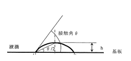
- FIG. 1 is an explanatory diagram showing a state in which the static contact angle ⁇ of the ink composition was measured in the examples.
- DPHA boiling point cannot be confirmed under atmospheric pressure conditions
- the ink composition (ii) shown in Table 2 is drawn at a dot pitch of 50 ⁇ m in the same manner as the ink jet discharge conditions of the ink composition (i) between the five lines of the space 60 ⁇ m obtained above. After drying at 80 ° C. for 3 minutes, exposure was performed at 1500 mJ / cm 2 and heat treatment was performed at 80 ° C. for 30 minutes. A boundary surface between the ink composition (i) drawn first and the ink composition (ii) drawn second time was observed with a microscope. When the overlap (color mixture) of two colored films is less than 5 ⁇ m or less, the ink composition (i) shown in Table 2 is applicable ( ⁇ ), and the ink colored film (ii) comprising the ink composition (ii) is ink. When it spreads over 5 ⁇ m or more on the ink-colored film (i) made of the composition (i), it was determined to be inappropriate ( ⁇ ), and the result is shown in Table 2 as ⁇ or ⁇ .
- each ink composition (i) shown in Table 2 was spin-coated on a 5-inch glass substrate, and a batch exposure machine (illuminance 50 mW / cm 2 ). Thus, 1500 mJ / cm 2 was irradiated to prepare a colored coating film substrate. 0.5 ⁇ l of each ink composition (ii) shown in Table 2 was dropped on this substrate, and the static contact angle was measured (h in the figure represents the height of the droplet). The results of the contact angle values are shown in Table 2.
Landscapes
- Chemical & Material Sciences (AREA)
- Physics & Mathematics (AREA)
- Organic Chemistry (AREA)
- Life Sciences & Earth Sciences (AREA)
- Optics & Photonics (AREA)
- Engineering & Computer Science (AREA)
- Materials Engineering (AREA)
- Wood Science & Technology (AREA)
- General Physics & Mathematics (AREA)
- Health & Medical Sciences (AREA)
- Chemical Kinetics & Catalysis (AREA)
- Medicinal Chemistry (AREA)
- Polymers & Plastics (AREA)
- Ink Jet Recording Methods And Recording Media Thereof (AREA)
- Inks, Pencil-Leads, Or Crayons (AREA)
- Optical Filters (AREA)
- Addition Polymer Or Copolymer, Post-Treatments, Or Chemical Modifications (AREA)
Abstract
Description

(式中、R1は、水素原子、メチル基、トリフルオロメチル基、又は塩素を示し、Xは炭素数1~6の2価の有機基を示し、Rfは、炭素数4~6のパーフルオロアルキル基を示し、また、Yは2価の基であって、共重合可能な不飽和基を有する単量体の残基である。)
CH2=C(R1)COOXRf (2)
(式中、R1は、水素原子、メチル基、トリフルオロメチル基、又は塩素を示し、Xは炭素数1~6の2価の有機基を示し、Rfは、炭素数4~6のパーフルオロアルキル基を示す。)
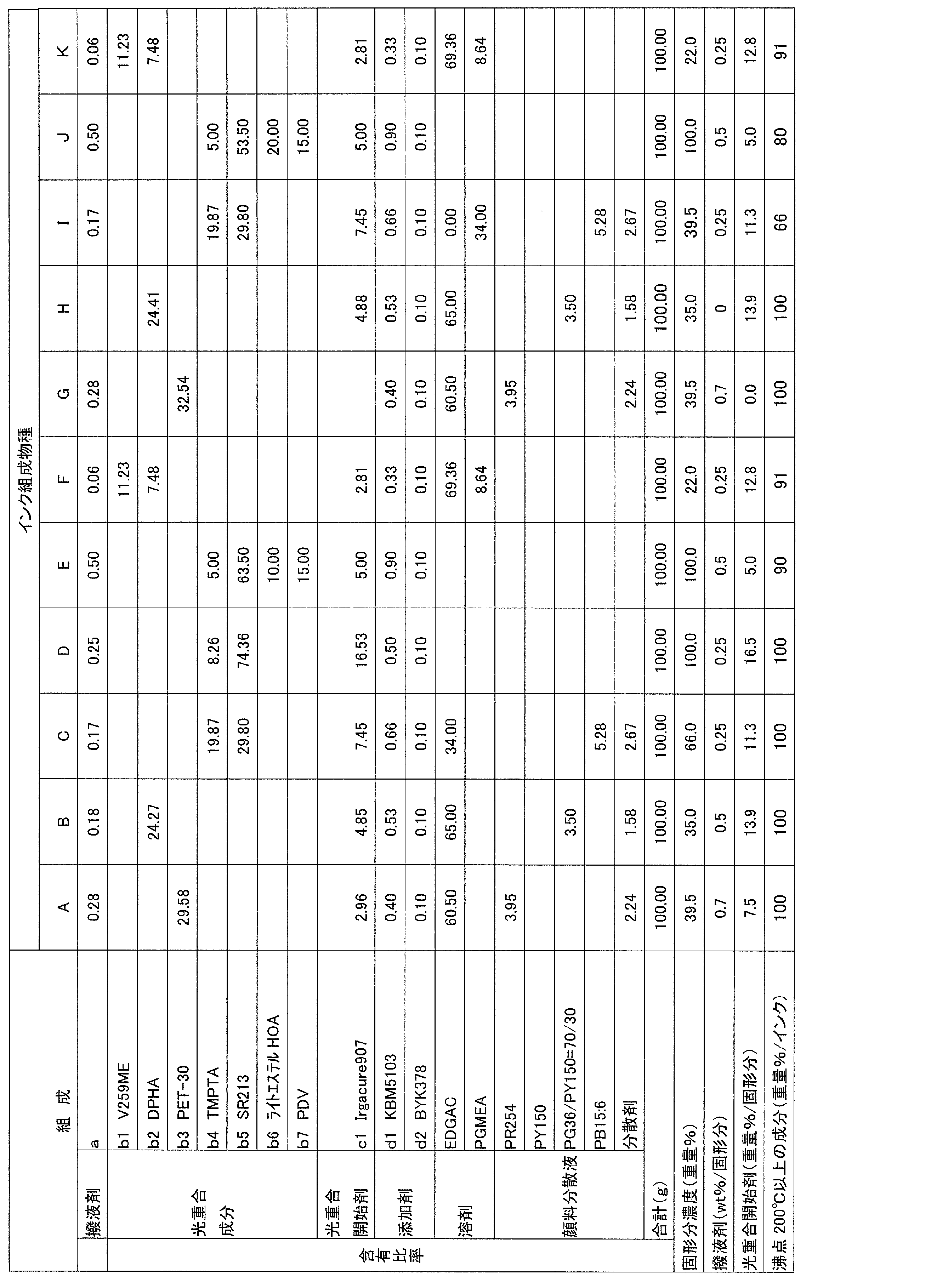
表1に示したように、先ず、カラーフィルター用微細顔料を用いて高分子分散剤を共存下、ジエチレングリコールモノエチルエーテルアセテートやプロピレングリコールモノメチルエーテルアセテートを溶媒としてビーズミル中で分散を行い、レッド、グリーン、ブルー、及びホワイトの分散液を調製した。この分散液をもとに表1に示す組成で混合し、1μmマイクロフィルターによって加圧ろ過を行い、各色の着色インクジェットインキ(インキ組成物)を調製した。
[a] フッ素含有撥液剤(ダイキン工業社製、商品名:オプツール DAC)
[b1] フルオレン型エポキシ型アクリレート/酸無水物重合付加体(新日鐵化学社製 V259-ME 沸点:大気圧条件で確認できない。3官能以上)
[b2] ジペンタエリスリトールヘキサアクリレートとジペンタエリスリトールペンタアクリレートとの混合物(日本化薬社製 DPHA 沸点:大気圧条件で確認できない。)
[b3] ペンタエリスリトールトリアクリレート(日本化薬社製 PET-30 沸点:大気圧条件で確認できない。)
[b4] トリメチロールプロパントリアクリレート(サートマー社製SR351S 沸点:大気圧条件で確認できない。)
[b5] 1,4-ブタンジオールジアクリレート(サートマー社SR213 沸点:大気圧条件で確認できない。)
[b6] 2-ヒドロキシエチルアクリレート(共栄社化学社製 ライトエステルHOA 沸点:190℃)
[b7] フェニルエチルメタクリレート末端ポリジビニルベンゼン(新日鐵化学製 PDV)
[c1] Irgcure907:2-メチル-1-〔4-(メチルチオ)フェニル〕-2-モルフォリノプロパン-1-オン(チバジャパン製)
[d1] KBM‐5103:3-アクリロキシプロピルトリメトキシシラン(信越化学工業製)
[d2] BYK-378:ポリエーテル変性ポリジメチルシロキサン系界面活性剤(ビッグへミー社製)
[EDGAC] ジエチレングリコールモノエチルエーテルアセテート(ダイセル化学製 沸点217℃)
[PGMEA] プロピレングリコールモノメチルエーテルアセテート(ダイセル化学製 沸点146℃)
[PR254]:ピグメントレッド254
[PY150]:ピグメントイエロー150
[PG36/PY150=50/50]:ピグメントグリーン36とピグメントイエロー150との共分散
[PB15:6]:ピグメントブルー15:6
<着色塗膜の境界面観察(着色塗膜の重なり性評価)>
先ず、表2に示したインキ組成物(i)を用いて、以下のようにして硬化膜を得た。すなわち、コニカミノルタ製インクジェットヘッド(KM512M、14pl仕様)を用いて、駆動周波数4.8kHz、14pl吐出可能な印加電圧にて、ヘッド温度23℃の条件でライン幅を70μmになるように打点ピッチを50μmに設定し、スペース60μmで5ラインを平行してインクジェット用PET基板上に描画した。次いで、80℃3分間乾燥後、紫外線照射器にて表2の露光量を照射した。
なお、静的接触角θ(図1参照)測定を目的に、5インチガラス基板上に表2に示す各インキ組成物(i)をスピンコートし、一括露光機(照度50mW/cm2)でもって1500mJ/cm2を照射し、着色塗膜基板を作成した。この基板上に表2に示す各インキ組成物(ii)を0.5μl滴下して静的接触角を測定した(図中のhは液滴高さを示す)。接触角値の結果を表2に示す。
コニカミノルタ製インクジェットヘッド(KM512M、14pl仕様)を用いて、駆動周波数4.8kHz、14pl吐出可能な印加電圧にて、ヘッド温度23℃条件において、インクジェット吐出性として連続吐出性や間欠吐出性を評価した。連続吐出試験は、10分間連続で吐出した後のノズル詰りを確認した。間欠吐出性は、10分間吐出を停止した後のノズル詰りを確認した。上記連続吐出性試験や間欠吐出性試験においてノズルの詰りが確認できなかったら良好(○)とし、どちらか1つの試験にノズルの詰りが発生したら不適(×)とし、表2に結果として○又は×を記入した。

Claims (5)
- 透明基板上にインクジェット方式でドットまたはストライプ状に印刷できる画像形成用樹脂組成物であって、含フッ素成分と光重合性成分と光重合開始剤とを少なくとも含むと共に、全組成物中に沸点200℃以上の成分を90重量%以上含み、該画像形成用樹脂組成物を用いて作製した硬化膜が、少なくとも光重合性成分と光重合開始剤とを含むと共に沸点200℃以上の成分を90重量%以上含んだ他のインキに対して35°以上の静的接触角θを示すことを特徴とする画像形成用樹脂組成物。
- 前記画像形成用樹脂組成物を用いて作製した硬化膜が、200mJ/cm2以上の紫外線を照射して得られるものである請求項1に記載に画像形成用樹脂組成物。
- 前記画像形成用樹脂組成物に含まれる含フッ素成分が、下記式(1)で示される構造からなる共重合体である請求項1又は2に記載の画像形成用樹脂組成物。

(式中、R1は、水素原子、メチル基、トリフルオロメチル基、又は塩素を示し、Xは炭素数1~6の2価の有機基を示し、Rfは、炭素数4~6のパーフルオロアルキル基を示し、また、Yは2価の基であって、共重合可能な不飽和基を有する単量体の残基である。) - 前記画像形成用樹脂組成物が、含フッ素成分を画像形成用樹脂組成物中の全固形分に対して0.05~10重量%含み、かつ、光重合開始剤を画像形成用樹脂組成物の全固形分に対して2~30重量%含む請求項1~3のいずれかに記載の画像形成用樹脂組成物。
- 請求項1~4のいずれかに記載の樹脂組成物をインクジェット方式により透明基板に塗布し、少なくとも紫外線照射工程を経て硬化した膜を画像形成用材料として使用した表示素子。
Priority Applications (3)
| Application Number | Priority Date | Filing Date | Title |
|---|---|---|---|
| CN201280017067.5A CN103460087B (zh) | 2011-03-31 | 2012-03-15 | 用于喷墨方式的图像形成用树脂组合物和显示元件 |
| JP2013507374A JP5876870B2 (ja) | 2011-03-31 | 2012-03-15 | インクジェット方式に用いる画像形成用樹脂組成物、表示素子の製造方法、及び画像形成方法 |
| KR1020137028424A KR20140032390A (ko) | 2011-03-31 | 2012-03-15 | 잉크젯 방식에 이용하는 화상 형성용 수지조성물 및 표시 소자 |
Applications Claiming Priority (2)
| Application Number | Priority Date | Filing Date | Title |
|---|---|---|---|
| JP2011-079576 | 2011-03-31 | ||
| JP2011079576 | 2011-03-31 |
Publications (1)
| Publication Number | Publication Date |
|---|---|
| WO2012132928A1 true WO2012132928A1 (ja) | 2012-10-04 |
Family
ID=46930663
Family Applications (1)
| Application Number | Title | Priority Date | Filing Date |
|---|---|---|---|
| PCT/JP2012/056687 Ceased WO2012132928A1 (ja) | 2011-03-31 | 2012-03-15 | インクジェット方式に用いる画像形成用樹脂組成物及び表示素子 |
Country Status (5)
| Country | Link |
|---|---|
| JP (1) | JP5876870B2 (ja) |
| KR (1) | KR20140032390A (ja) |
| CN (1) | CN103460087B (ja) |
| TW (1) | TWI525112B (ja) |
| WO (1) | WO2012132928A1 (ja) |
Cited By (1)
| Publication number | Priority date | Publication date | Assignee | Title |
|---|---|---|---|---|
| CN103838082A (zh) * | 2012-11-21 | 2014-06-04 | 新日铁住金化学株式会社 | 喷墨基底用处理剂 |
Citations (6)
| Publication number | Priority date | Publication date | Assignee | Title |
|---|---|---|---|---|
| JP2000310706A (ja) * | 1999-04-27 | 2000-11-07 | Seiko Epson Corp | インクジェット方式カラーフィルタ用樹脂組成物、カラーフィルタおよびカラーフィルタの製造方法 |
| JP2006291077A (ja) * | 2005-04-12 | 2006-10-26 | Catalysts & Chem Ind Co Ltd | 低屈折率膜形成用組成物およびその硬化膜付基材 |
| JP2008076651A (ja) * | 2006-09-20 | 2008-04-03 | Fujifilm Corp | 撥インク性隔壁及びその製造方法、カラーフィルタ及びその製造方法、並びに表示装置 |
| JP2008195877A (ja) * | 2007-02-15 | 2008-08-28 | Dainippon Printing Co Ltd | カラーフィルター用インクジェットインク及びその製造方法、カラーフィルターの製造方法、並びに液晶表示装置の製造方法 |
| JP2009128370A (ja) * | 2007-11-19 | 2009-06-11 | Dainippon Printing Co Ltd | カラーフィルター |
| JP2010201821A (ja) * | 2009-03-04 | 2010-09-16 | Asahi Kasei E-Materials Corp | 光重合性樹脂積層体、並びにこれを用いた表面撥液性パターン基板、カラーフィルタ、有機エレクトロルミネッセンス素子及び電子ペーパーの製造方法 |
Family Cites Families (1)
| Publication number | Priority date | Publication date | Assignee | Title |
|---|---|---|---|---|
| JP2007079197A (ja) * | 2005-09-15 | 2007-03-29 | Toppan Printing Co Ltd | カラーフィルタ、ディスプレイおよびそれらの製造方法 |
-
2012
- 2012-03-15 KR KR1020137028424A patent/KR20140032390A/ko not_active Withdrawn
- 2012-03-15 WO PCT/JP2012/056687 patent/WO2012132928A1/ja not_active Ceased
- 2012-03-15 CN CN201280017067.5A patent/CN103460087B/zh not_active Expired - Fee Related
- 2012-03-15 JP JP2013507374A patent/JP5876870B2/ja not_active Expired - Fee Related
- 2012-03-22 TW TW101109849A patent/TWI525112B/zh not_active IP Right Cessation
Patent Citations (6)
| Publication number | Priority date | Publication date | Assignee | Title |
|---|---|---|---|---|
| JP2000310706A (ja) * | 1999-04-27 | 2000-11-07 | Seiko Epson Corp | インクジェット方式カラーフィルタ用樹脂組成物、カラーフィルタおよびカラーフィルタの製造方法 |
| JP2006291077A (ja) * | 2005-04-12 | 2006-10-26 | Catalysts & Chem Ind Co Ltd | 低屈折率膜形成用組成物およびその硬化膜付基材 |
| JP2008076651A (ja) * | 2006-09-20 | 2008-04-03 | Fujifilm Corp | 撥インク性隔壁及びその製造方法、カラーフィルタ及びその製造方法、並びに表示装置 |
| JP2008195877A (ja) * | 2007-02-15 | 2008-08-28 | Dainippon Printing Co Ltd | カラーフィルター用インクジェットインク及びその製造方法、カラーフィルターの製造方法、並びに液晶表示装置の製造方法 |
| JP2009128370A (ja) * | 2007-11-19 | 2009-06-11 | Dainippon Printing Co Ltd | カラーフィルター |
| JP2010201821A (ja) * | 2009-03-04 | 2010-09-16 | Asahi Kasei E-Materials Corp | 光重合性樹脂積層体、並びにこれを用いた表面撥液性パターン基板、カラーフィルタ、有機エレクトロルミネッセンス素子及び電子ペーパーの製造方法 |
Cited By (1)
| Publication number | Priority date | Publication date | Assignee | Title |
|---|---|---|---|---|
| CN103838082A (zh) * | 2012-11-21 | 2014-06-04 | 新日铁住金化学株式会社 | 喷墨基底用处理剂 |
Also Published As
| Publication number | Publication date |
|---|---|
| JP5876870B2 (ja) | 2016-03-02 |
| CN103460087A (zh) | 2013-12-18 |
| JPWO2012132928A1 (ja) | 2014-07-28 |
| TWI525112B (zh) | 2016-03-11 |
| CN103460087B (zh) | 2016-01-20 |
| TW201307405A (zh) | 2013-02-16 |
| KR20140032390A (ko) | 2014-03-14 |
Similar Documents
| Publication | Publication Date | Title |
|---|---|---|
| KR101479475B1 (ko) | 컬러 필터 및 액정 표시장치의 제조 방법 | |
| JP4844450B2 (ja) | カラーフィルターの製造方法及びカラーフィルター | |
| JP4544292B2 (ja) | カラーフィルター用インク、カラーフィルター、画像表示装置、および、電子機器 | |
| JP5858835B2 (ja) | カラーフィルター用紫外線硬化性インキ受容層及びカラーフィルターの製造方法 | |
| JP2013238812A (ja) | 感光性青色着色組成物 | |
| JP2009145719A (ja) | カラーフィルター用インク、カラーフィルター用インクセット、カラーフィルター、画像表示装置、および、電子機器 | |
| JP4527489B2 (ja) | カラーフィルター用熱硬化性樹脂組成物、カラーフィルター、液晶パネル、及びカラーフィルターの製造方法 | |
| JP4619904B2 (ja) | カラーフィルター用インクジェットインク、カラーフィルター、及び液晶表示装置 | |
| JP2013195545A (ja) | カラー表示装置用カラーフィルター | |
| JP5876870B2 (ja) | インクジェット方式に用いる画像形成用樹脂組成物、表示素子の製造方法、及び画像形成方法 | |
| JP4742648B2 (ja) | カラーフィルター用インクジェットインク及びその製造方法、カラーフィルターの製造方法、並びに液晶表示装置の製造方法 | |
| JP2015180959A (ja) | カラーフィルターの製造方法、カラーフィルター、及び反射型表示装置 | |
| JP4522915B2 (ja) | カラーフィルター用インクジェットインク、カラーフィルター、及び液晶表示装置 | |
| JP5286657B2 (ja) | 顔料分散液、カラーフィルター用インクジェットインク及びその製造方法、カラーフィルター、並びに液晶表示装置 | |
| JP2012252182A (ja) | カラーフィルターの製造方法、カラーフィルター、及び反射型表示装置 | |
| JP2009300724A (ja) | カラーフィルター用インク、カラーフィルター、画像表示装置、および、電子機器 | |
| JP2013195547A (ja) | カラーフィルターの製造方法 | |
| JP2009169221A (ja) | カラーフィルター用インクセット、カラーフィルターの製造方法、カラーフィルター、画像表示装置、および、電子機器 | |
| JP2012201875A (ja) | 青色顔料分散液、カラーフィルタ用青色ネガ型レジスト組成物、カラーフィルタ、液晶表示装置、及び有機発光表示装置 | |
| JP2009086285A (ja) | カラーフィルタ及びその製造方法並びに表示装置 | |
| JP2011002550A (ja) | スペーサ付カラーフィルタ基板の製造方法 | |
| JP2009186878A (ja) | 洗浄液および液滴吐出装置 | |
| JP2009169223A (ja) | カラーフィルター用インク、カラーフィルター、画像表示装置、および、電子機器 | |
| JP2007171656A (ja) | カラーフィルタ及びその製造方法並びに液晶表示装置 | |
| JP2009244817A (ja) | カラーフィルタの製造方法 |
Legal Events
| Date | Code | Title | Description |
|---|---|---|---|
| 121 | Ep: the epo has been informed by wipo that ep was designated in this application |
Ref document number: 12764226 Country of ref document: EP Kind code of ref document: A1 |
|
| DPE1 | Request for preliminary examination filed after expiration of 19th month from priority date (pct application filed from 20040101) | ||
| ENP | Entry into the national phase |
Ref document number: 2013507374 Country of ref document: JP Kind code of ref document: A |
|
| NENP | Non-entry into the national phase |
Ref country code: DE |
|
| ENP | Entry into the national phase |
Ref document number: 20137028424 Country of ref document: KR Kind code of ref document: A |
|
| 122 | Ep: pct application non-entry in european phase |
Ref document number: 12764226 Country of ref document: EP Kind code of ref document: A1 |